Climax Technology Co LMHTZB Ambient Light, Humidity and Temperature Sensor User Manual LMHT 1ZBS 20160330 FCCx
Climax Technology Co Ltd Ambient Light, Humidity and Temperature Sensor LMHT 1ZBS 20160330 FCCx
Users Manual
1
LMHT-1ZBS Ambient Light, Humidity and Temperature Sensor
Introduction
LMHT-1ZBS is a ZigBee Ambient Light, Humidity and Temperature Sensor. It monitors your home environment and
transmits measured Illuminance (lux), humidity and temperature to the coordinator in the ZigBee network.
The sensor utilizes ZigBee technology for wireless signal transmission. ZigBee is a wireless communication protocol that is
reliable, has low power consumption and high transmission efficiency. Based on the IEEE802.15.4 standard, ZigBee allows
a large amount of devices to be included in a network and coordinated for data exchange and signal transmission.
The sensor serves as an end device in the ZigBee network. It can be included in the ZigBee network to transmit signal
upon activation, but cannot permit any other ZigBee device to join the network through the sensor.
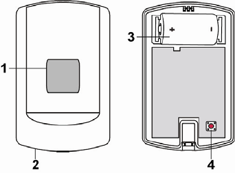
Parts Identification
1. Light Sensor / LED Indicator
- Flashes once: Factory Reset
- Flashes twice: After the sensor has successfully joined a ZigBee
network.
- Flashes 3 times: Battery inserted.
- Flashes 5 times: Low battery detected when inserting battery.
- Flashes once every 20 minutes: The sensor has lost connection to
its current ZigBee network.
2. Temperature Sensor
3. Battery Compartment
4. Function Button
- Press once to send a signal to the coordinator.
- Press and hold for 10 seconds to reset the device.
Features
Lighting, Humidity and Temperature Monitoring
The sensor measures illuminance, humidity and temperature to transmit measured data to ZigBee network
coordinator regularly.
Illuminance reading is transmitted every 30 minutes.
Humidity and temperature reading is transmitted every 10 minutes.
The sensor will also transmit signal automatically when:
The temperature changes by +/- 2°C.
Humidity changes +/- 10%.
When the current illuminance changes by +/- 10%.
You can also press the Function Button once to transmit current reading manually.
Battery and Low Battery Detection
The sensor uses one CR123A 3V Lithium battery as its power source.
The sensor features Low Battery Detection function. When the battery voltage is low, the sensor will transmit Low
Battery signal to the coordinator in ZigBee network
When changing battery, after removing the old batteries, press the Function Button twice to fully discharge before
inserting new battery.
If low battery voltage is detected upon inserting new battery, the LED indicator will flash 5 times.
Supervision
The sensor will transmit a supervision signal along with the reading signal to report its condition regularly. The factory
default interval is 30 minutes, which can be adjusted according to setting.
ZigBee Network Setup
2
ZigBee Device Guideline
ZigBee is a wireless communication protocol that is reliable and has low power consumption and high transmission
efficiency. Based on the IEEE802.15.4 standard, ZigBee allows a large amount of devices to be included in a network
and coordinated for data exchange and signal transmission.
Due to the fundamental structure of ZigBee network, ZigBee device will actively seek and join network after powering
on. Since performing a task in connecting network may consume some power, it is required to follow the instructions to
avoid draining battery of a ZigBee device
- Ensure your ZigBee network router or coordinator is powered on before inserting battery into the ZigBee device.
- Ensure the ZigBee network router or coordinator is powered on and within range while a ZigBee device is in use.
- Do not remove a ZigBee device from the ZigBee network router or coordinator without removing the battery from a
ZigBee device.
Joining the ZigBee Network
As a ZigBee device, the sensor needs to join a ZigBee network to transmit signal. Please follow the steps below to join
the sensor into the ZigBee network.
1. Detach the Top Cover and Base assembly and insert battery.
2. Press and hold the function button for 10 seconds as the sensor resets (LED flashes once) and starts searching for
existing ZigBee network. Please make sure the permit-to-join feature on the router or coordinator of your ZigBee
network is enabled.
3. If the sensor successfully joins a ZigBee network, the LED Indicator will flash twice to confirm.
4. After joining the ZigBee network, the sensor will be registered in the network automatically. Please check your
ZigBee coordinator, system control panel or CIE (Control and Indicating Equipment) to confirm if joining and
registration is successful.
5. After joining the ZigBee network, if the sensor loses connection with current ZigBee network, the LED will flash
every 20 minutes to indicate. Please check your ZigBee network condition and sensor signal range to correct the
situation.
Removing Device from ZigBee Network (Factory Reset)
To remove the Power Switch from current ZigBee network, the sensor must be put to Factory Reset to complete
device removal. Factory Reset function will clear the device of its stored setting information and prompt the sensor to
search for new ZigBee network.
Before removing device, make sure the sensor is within current ZigBee network signal range
1. Press and hold the function button for 10 seconds, then release the button to reset sensor.
2. Upon reset, the sensoe will clear current ZigBee network setting and transmit signal to ZigBee coordinator to
remove itself from current ZigBee network. It will then actively search for available ZigBee network again and join
the network automatically.
Installation
Mounting the Sensor
The sensor can be mounted using two methods: Self-adhesive or Screw mounting.
Self adhesive mounting
1. Clean the surface with a suitable degreaser.
2. Remove the protective covering from one side of double-sided adhesive pad and firmly apply to the back of the
device.
3. Remove the other covering and firmly place/press the device in the desired location.
Do not use the Self-adhesive mounting method on poorly painted and/or rough surfaces.
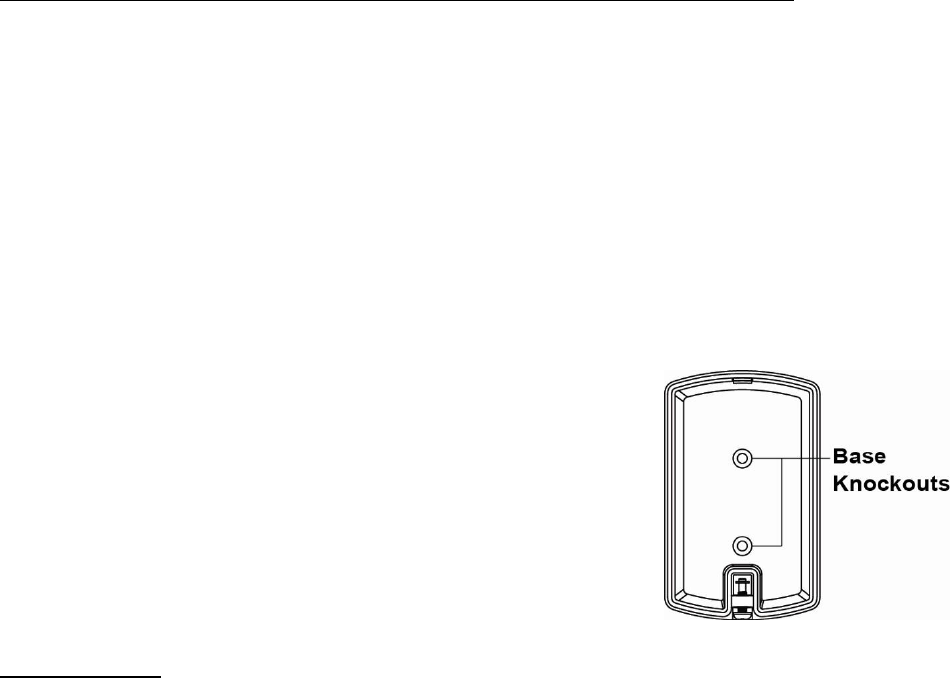
Screw Mounting
The base of the sensor has two screw knockouts, where the plastic is thinner for
mounting purposes. To mount the sensor:
1. Detach the Top Cover and Base assembly by loosening the Cover-Fixing
Screw using a Philips screwdriver.
2. Break through the knockouts on the base.
3. Use the holes as a template to drill two holes and insert the wall plugs.
4. Screw the base into the wall plugs.
5. Replace the top cover over the base by hooking the base onto the fixing hook
and pushing the cover towards the base.
6. Secure and screw the top cover back on to its base using a Philips screwdriver.
Using the Sensor with ZigBee Router
IMPORTANT NOTE
If the sensor installation location is away from your system control panel and requires ZigBee routers to improve

3
signal strength. DO NOT use a ZigBee Router without backup battery. A ZigBee router without battery will be powered
down during AC power failure and the sensor connected to the router will lose connection with ZigBee network. You
should plan your sensor installation location using only ZigBee router with backup battery.
Appendix
(The Appendix information is for developers only.)
Light Sensor Cluster ID
Device ID: Room Sensor 0x0302
Endpoint: 0x01
Server Side Client Side
Mandatory
Basic (0x0000) Basic (0x0000)
Identify(0x0003) Identify(0x0003)
Illuminance Measurement (0x0400)
Optional
Power Configuration(0x0001) None
Temperature Measurement(0x0402)
Relative Humidity Measurement(0x0405)
Attribute of Basic Cluster Information
Identifier Name Type Range Access Default
Mandatory
/ Optional
0x0000 ZCLVersion Unsigned 8-bit
integer 0x00 –0xff Read
only 0x01 M
0x0001 ApplicationVersion
Unsigned 8-bit
integer 0x00 –0xff Read
only 0x00 O
0x0003 HWVersion Unsigned 8-bit
integer 0x00 –0xff Read
only 0 O
0x0004 ManufacturerName Character
String 0 – 32 bytes Read
only Climax
Technology O
0x0005 ModelIdentifier Character
String 0 – 32 bytes Read
only (Model Version) O
0x0006 DateCode Character
String 0 – 16 bytes Read
only O
0x0007 PowerSource 8-bit 0x00 –0xff
Read
only M
0x0010 LocationDescription Character
String 0 – 32 bytes Read /
Write O
0x0011 PhysicalEnvironment 8-bit 0x00 –0xff
Read /
Write 0x00 O
0x0012 DeviceEnabled Boolean 0x00 –0x01
Read /
Write 0x01 M
Attribute of Identify Cluster Information
Identifier Name Type Range Access Default
Mandatory
/ Optional
0x0000 IdentifyTime Unsigned
16-bit integer 0x00 –0xffff Read /
Write 0x0000 M
Attribute of Power Configuration Cluster Information
Identifier Name Type Range Access Default
Mandatory
/ Optional
0x0035 BatteryAlarmMask 8-bit
bitmap 0000 000x Read /
Write 0000 0000 O
Attribute of Illuminance Measurement Cluster Information
Identifier Name Type Range Access Default
Mandatory
/ Optional

4
0x0000 MeasuredValue Signed 16-bit
Integer
MinMeasuredValue
to
MaxMeasuredValue
Read
only 0x00 M
0x0001 MinMeasuredValue Signed 16-bit
Integer 0x0002 – 0xfffd Read
only - M
0x0002 MaxMeasuredValue Signed 16-bit
Integer 0x0001 – 0xfffe Read
only - M
Attribute of Temperature Measurement Cluster Information
Identifier Name Type Range Access Default
Mandatory
/ Optional
0x0000 MeasuredValue Signed 16-bit
Integer
MinMeasuredValue
to
MaxMeasuredValue
Read
only 0x00 M
0x0001 MinMeasuredValue Signed 16-bit
Integer 0x954d – 0x7ffe Read
only -1000
(-10℃) M
0x0002 MaxMeasuredValue Signed 16-bit
Integer 0x954e – 0x7fff Read
only 5000
(50℃) M
0x0003 Tolerance
Unsigned 16-bit
Integer 0x0000 – 0x0800 Read
only 100
(1℃) O
Attribute of Relative Humidity Measurement Cluster Information
Identifier Name Type Range Access Default
Mandatory
/ Optional
0x0000 MeasuredValue
Unsigned 16-bit
Integer
MinMeasuredValue
to
MaxMeasuredValue
Read
only M
0x0001 MinMeasuredValue Unsigned 16-bit
Integer 0x0000 – 0x270f Read
only 0
(0%) M
0x0002 MaxMeasuredValue Unsigned 16-bit
Integer 0x0001 – 0x2710 Read
only 10000
(100%) M
0x0003 Tolerance
Unsigned 16-bit
Integer 0x0000 – 0x0800 Read
only 200
(2%) O
5
Federal Communication Commission Interference Statement
This equipment has been tested and found to comply with the limits for a Class B
digital device, pursuant to Part 15 of the FCC Rules. These limits are designed to
provide reasonable protection against harmful interference in a residential
installation.
This equipment generates, uses and can radiate radio frequency energy and, if not
installed and used in accordance with the instructions, may cause harmful
interference to radio communications. However, there is no guarantee that
interference will not occur in a particular installation. If this equipment does cause
harmful interference to radio or television reception, which can be determined by
turning the equipment off and on, the user is encouraged to try to correct the
interference by one of the following measures:
. Reorient or relocate the receiving antenna.
. Increase the separation between the equipment and receiver.
. Connect the equipment into an outlet on a circuit different from that to which the
receiver is connected.
. Consult the dealer or an experienced radio/TV technician for help.
FCC Caution
: To assure continued compliance, any changes or modifications not
expressly approved by the party responsible for compliance could void the user's
authority to operate this equipment. (Example - use only shielded interface cables
when connecting to computer or peripheral devices).
FCC Radiation Exposure Statement
This equipment complies with FCC RF radiation exposure limits set forth for an
uncontrolled environment. This equipment should be installed and operated with a
minimum distance of 20 centimeters between the radiator and your body.
This transmitter must not be co-located or operating in conjunction with any other
antenna or transmitter.
The antennas used for this transmitter must be installed to provide a separation
distance of at least 20 cm from all persons and must not be co-located or operating
in conjunction with any other antenna or transmitter.
This device complies with Part 15 of the FCC Rules. Operation is subject to the
following two conditions:
(1) This device may not cause harmful interference, and
(2) This device must accept any interference received, including interference that
may cause undesired operation.