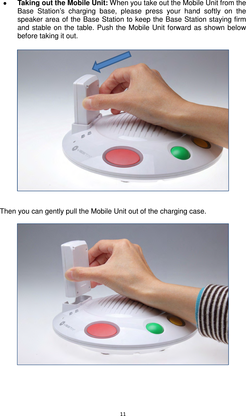
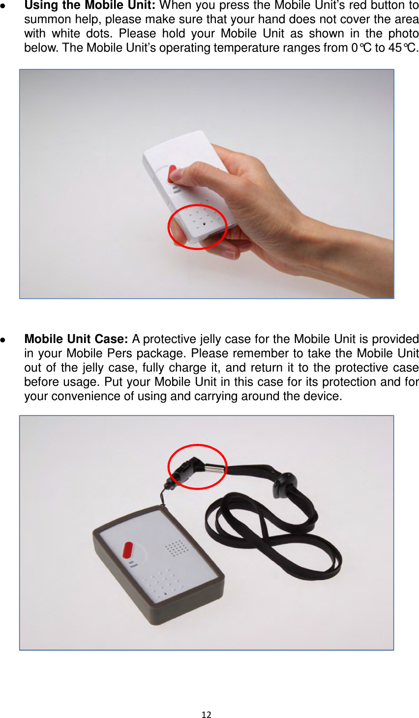
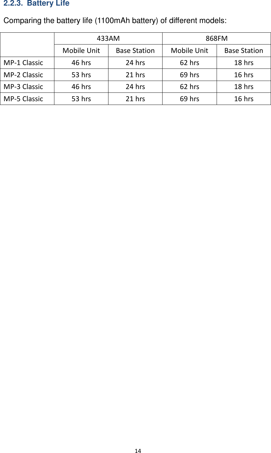
Climax Technology Co MP Mobile Pers cellular medical alarm system User Manual
Climax Technology Co Ltd Mobile Pers cellular medical alarm system Users Manual
UserManual.wiki
>
Climax Technology Co
>
MP User Manual
Users Manual
Navigation menu
Upload a User Manual
Namespaces
Wiki Guide
HTML
PDF
Info
Views
User Manual
Discussion / Help
Navigation
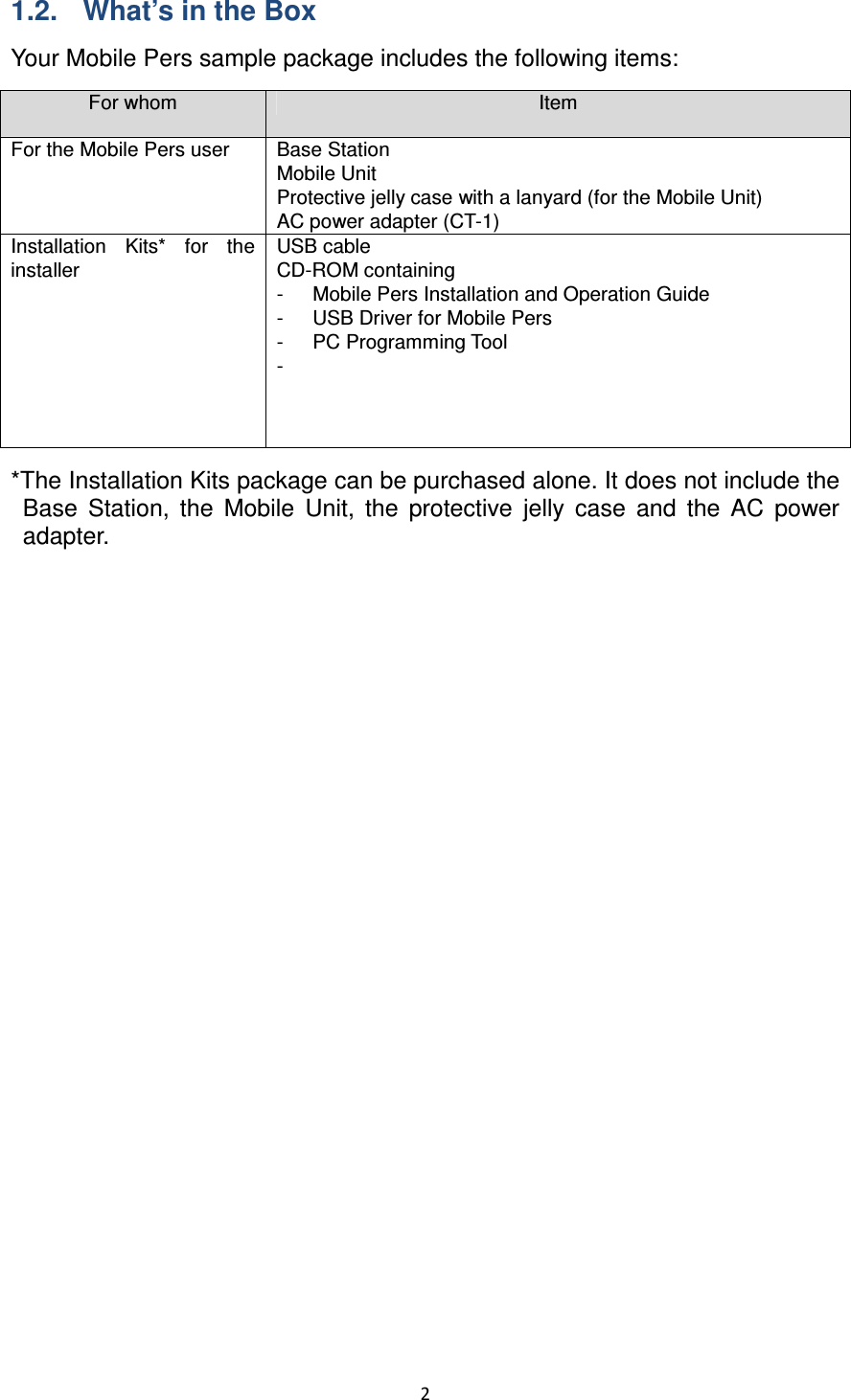

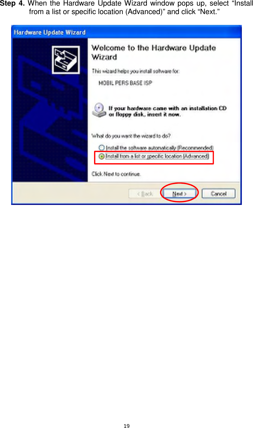
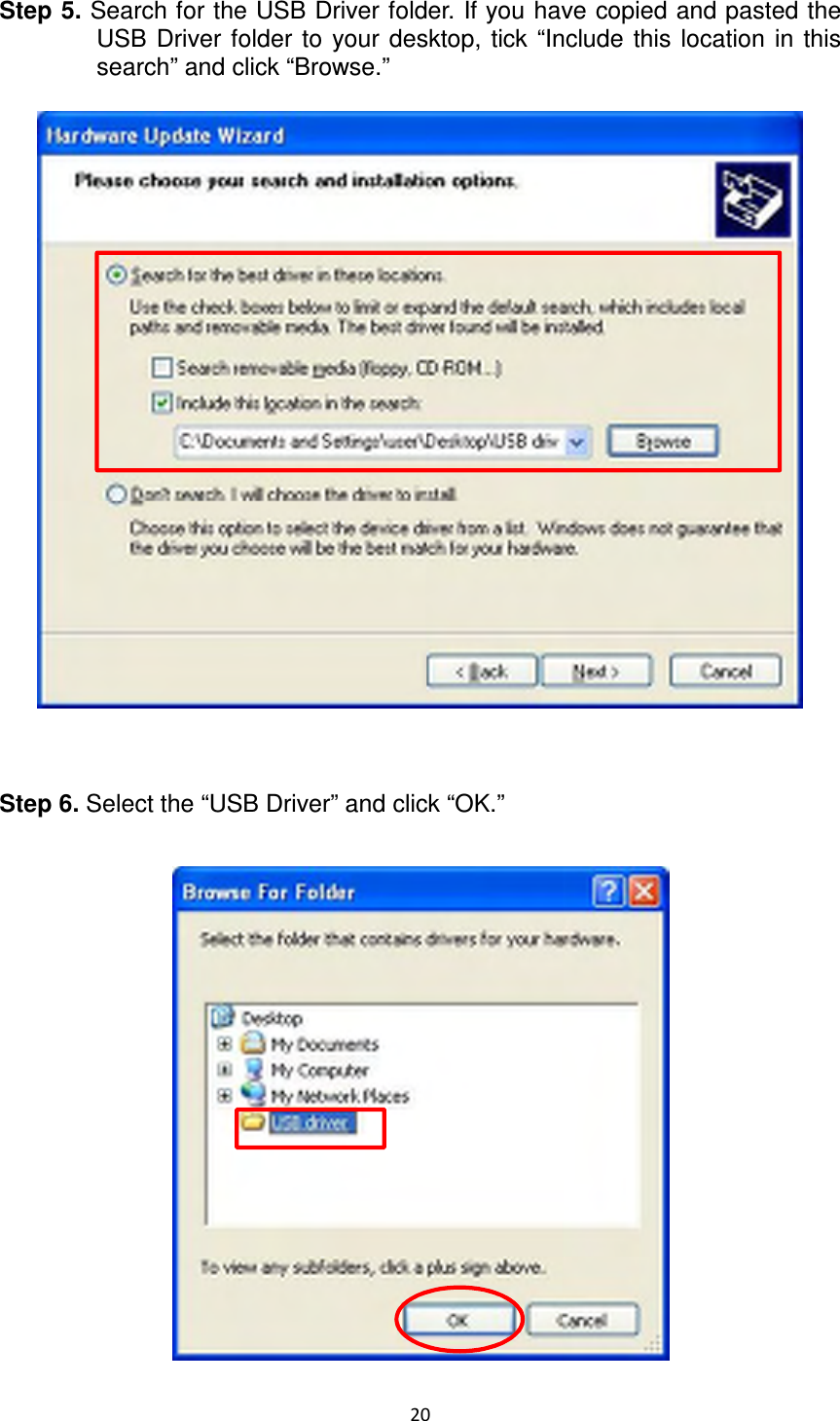
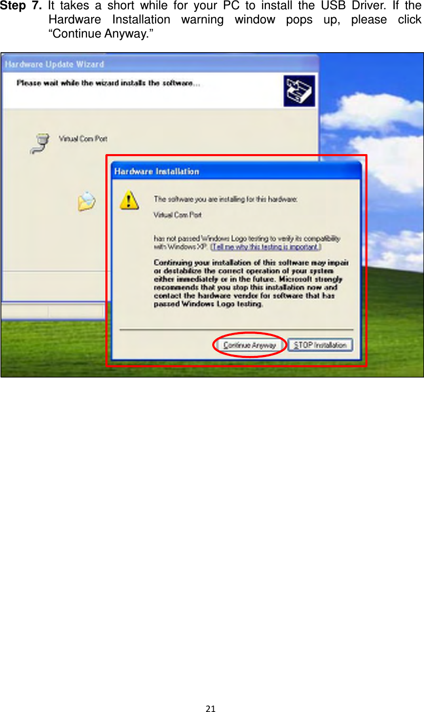
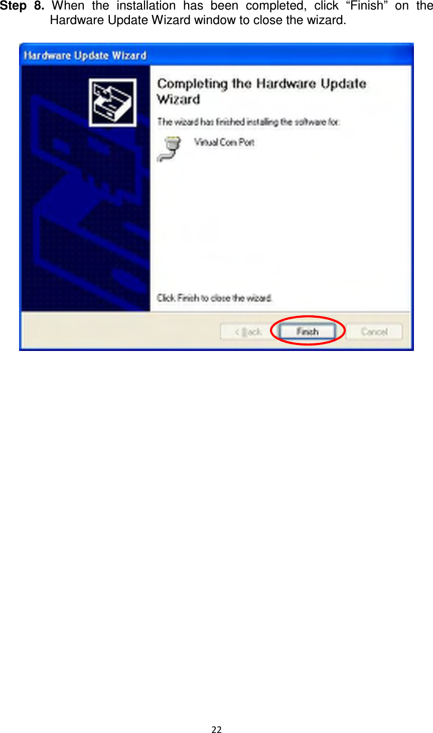
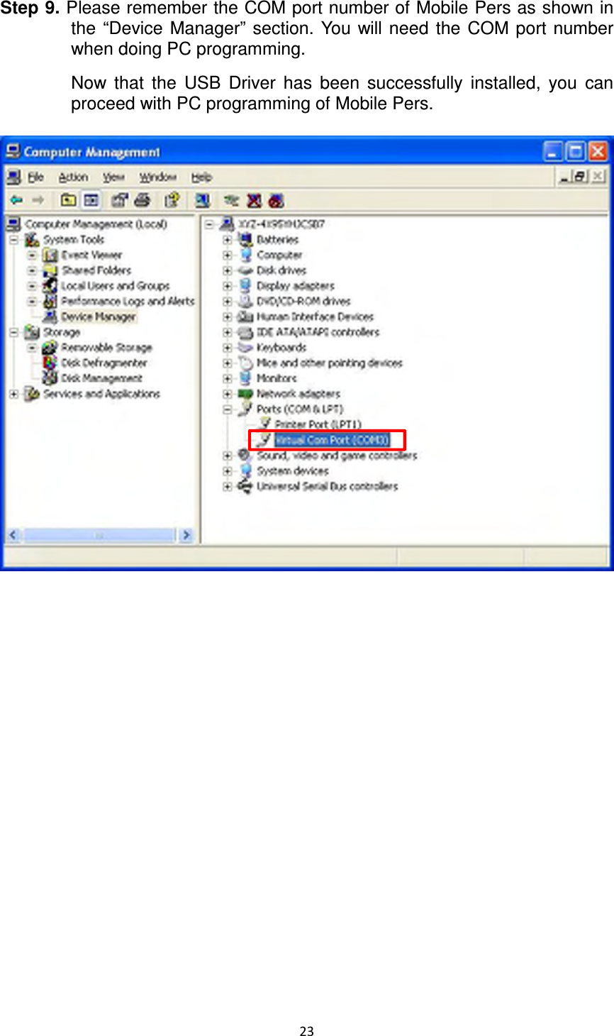
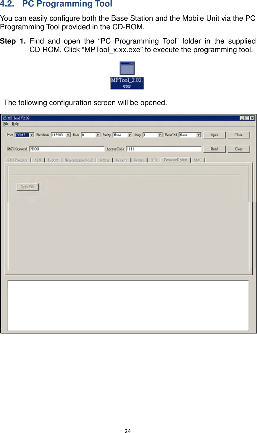
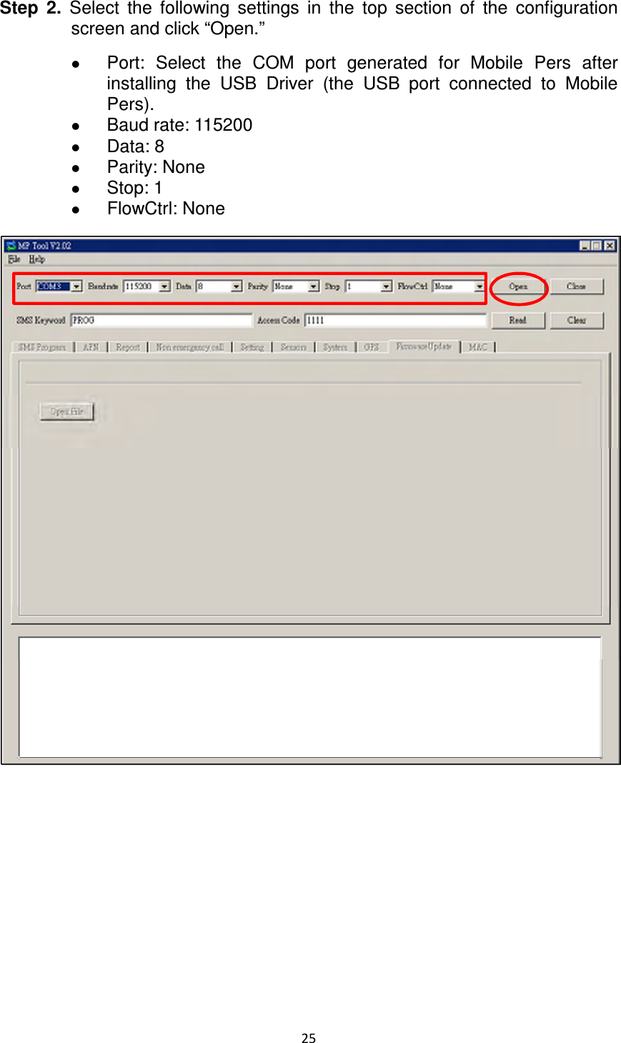
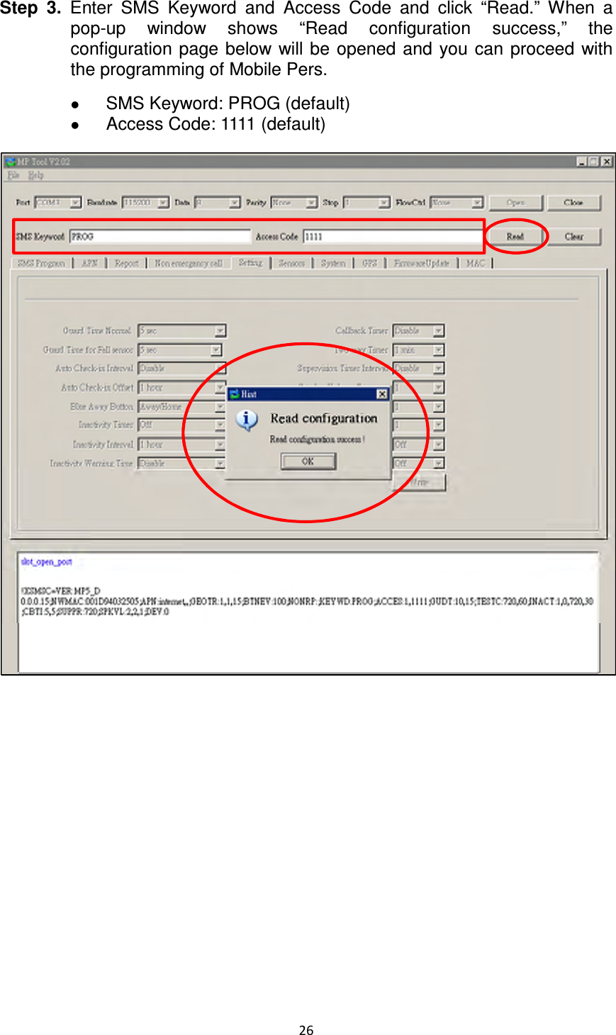
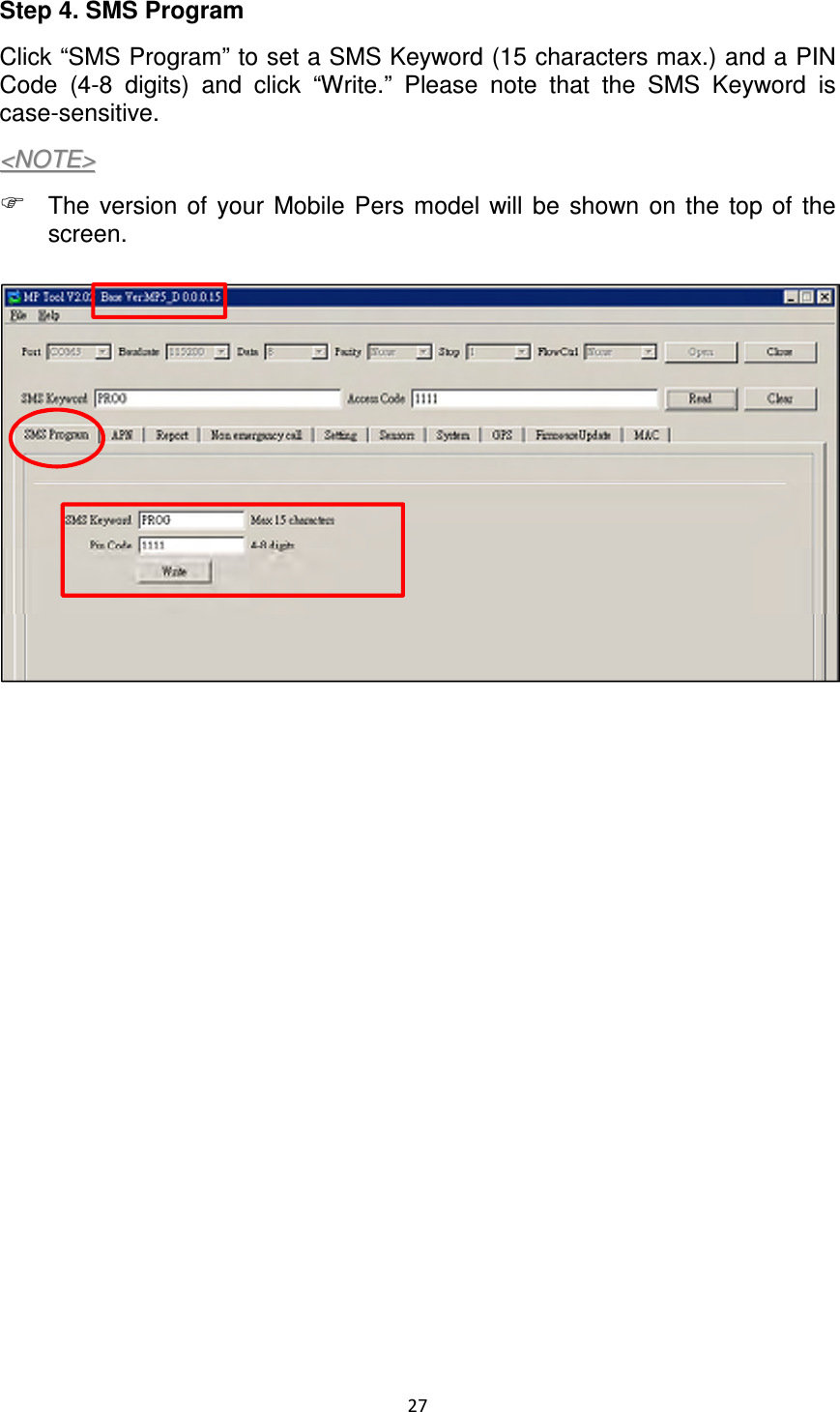
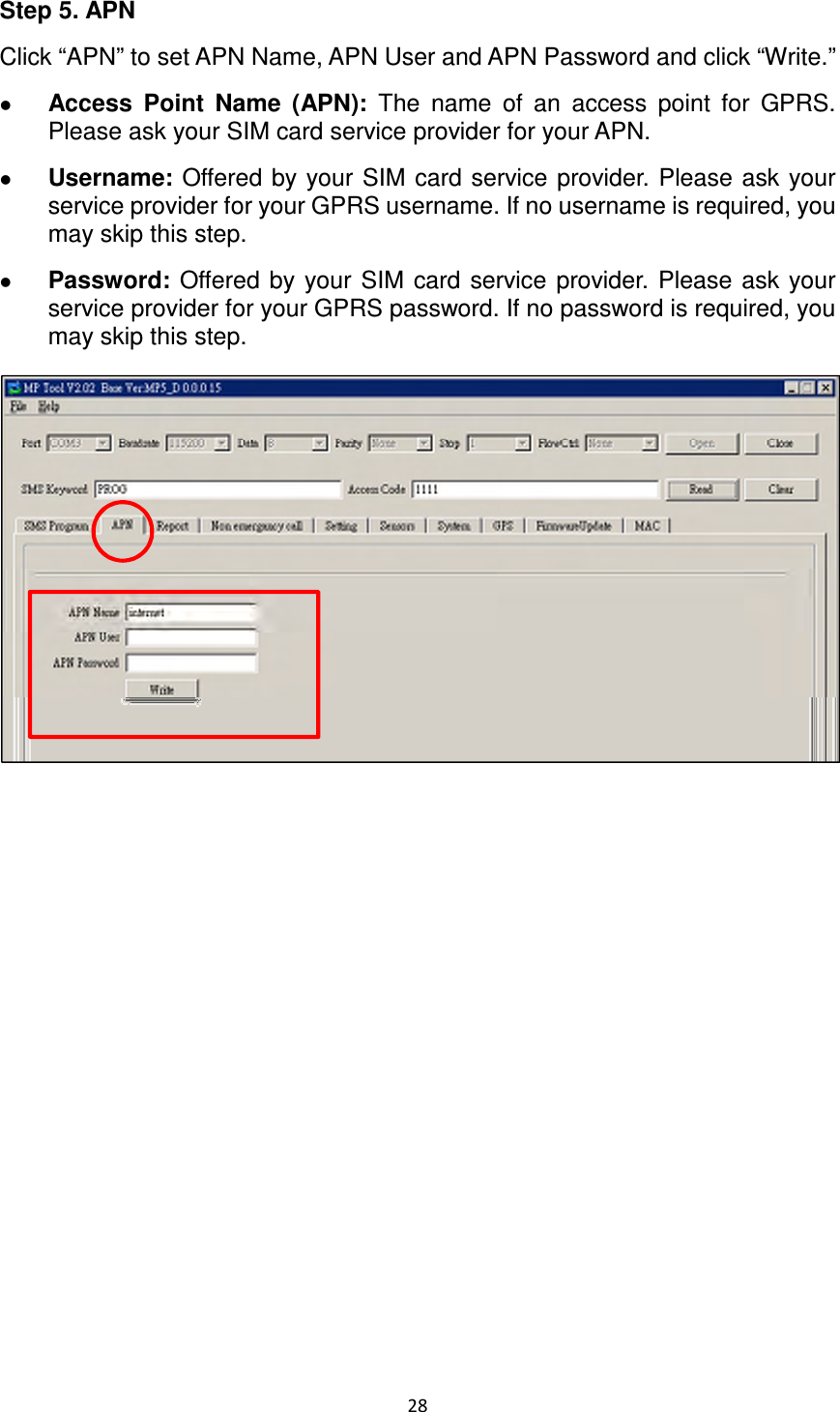
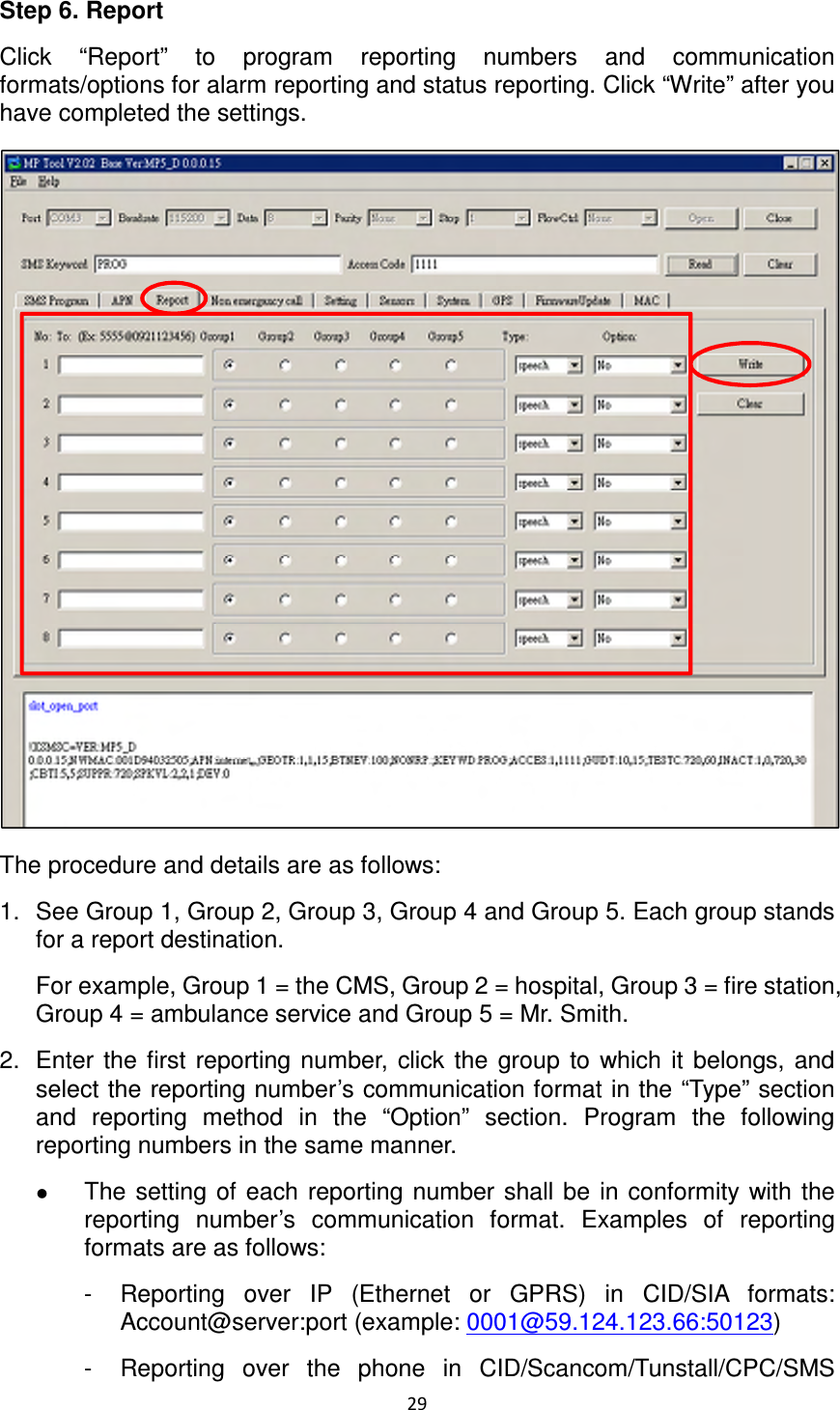
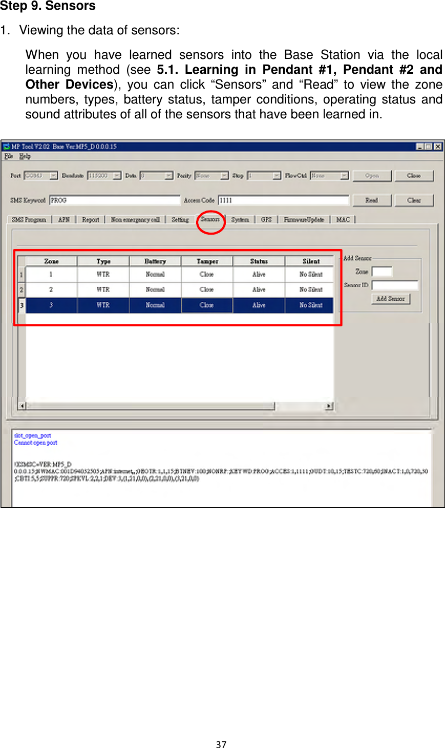
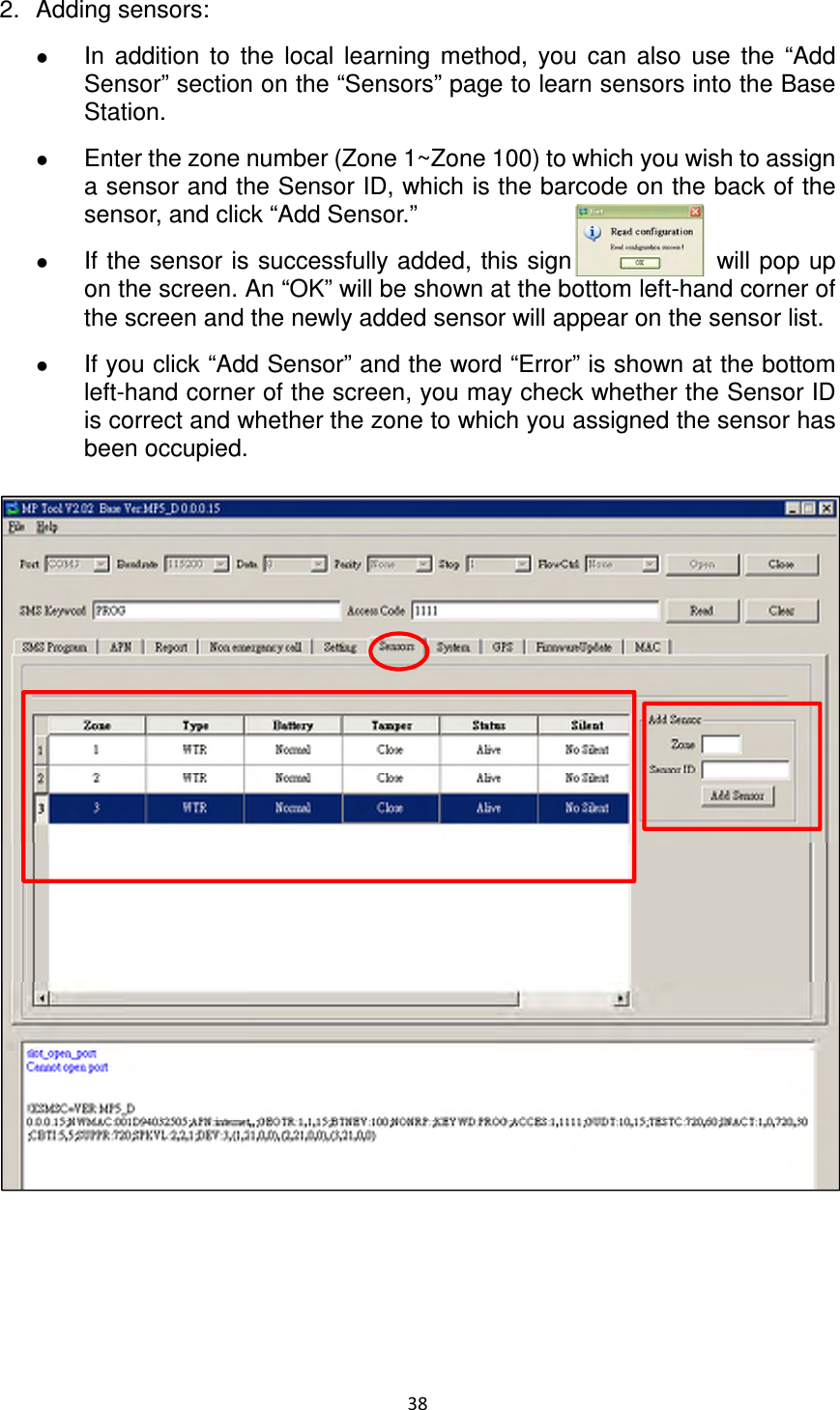
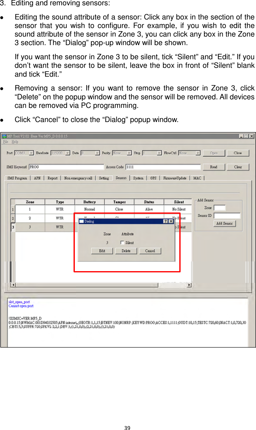
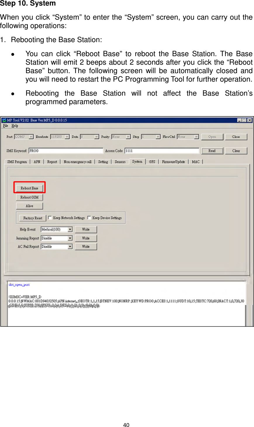
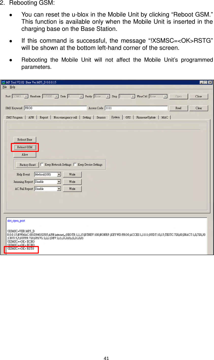
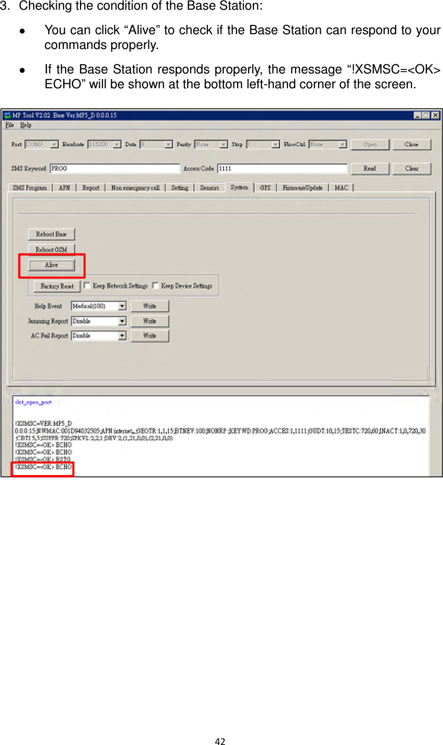
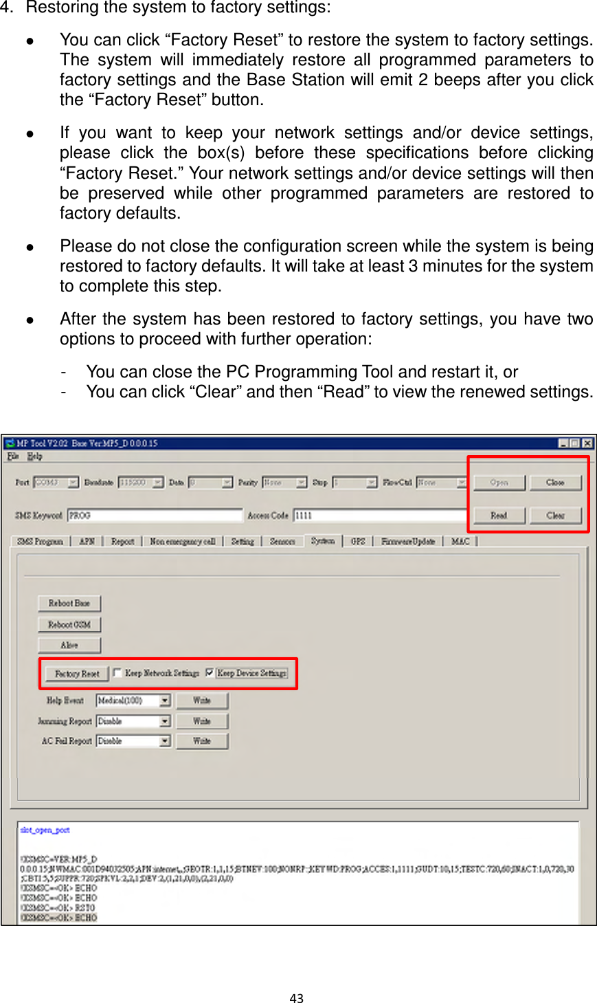
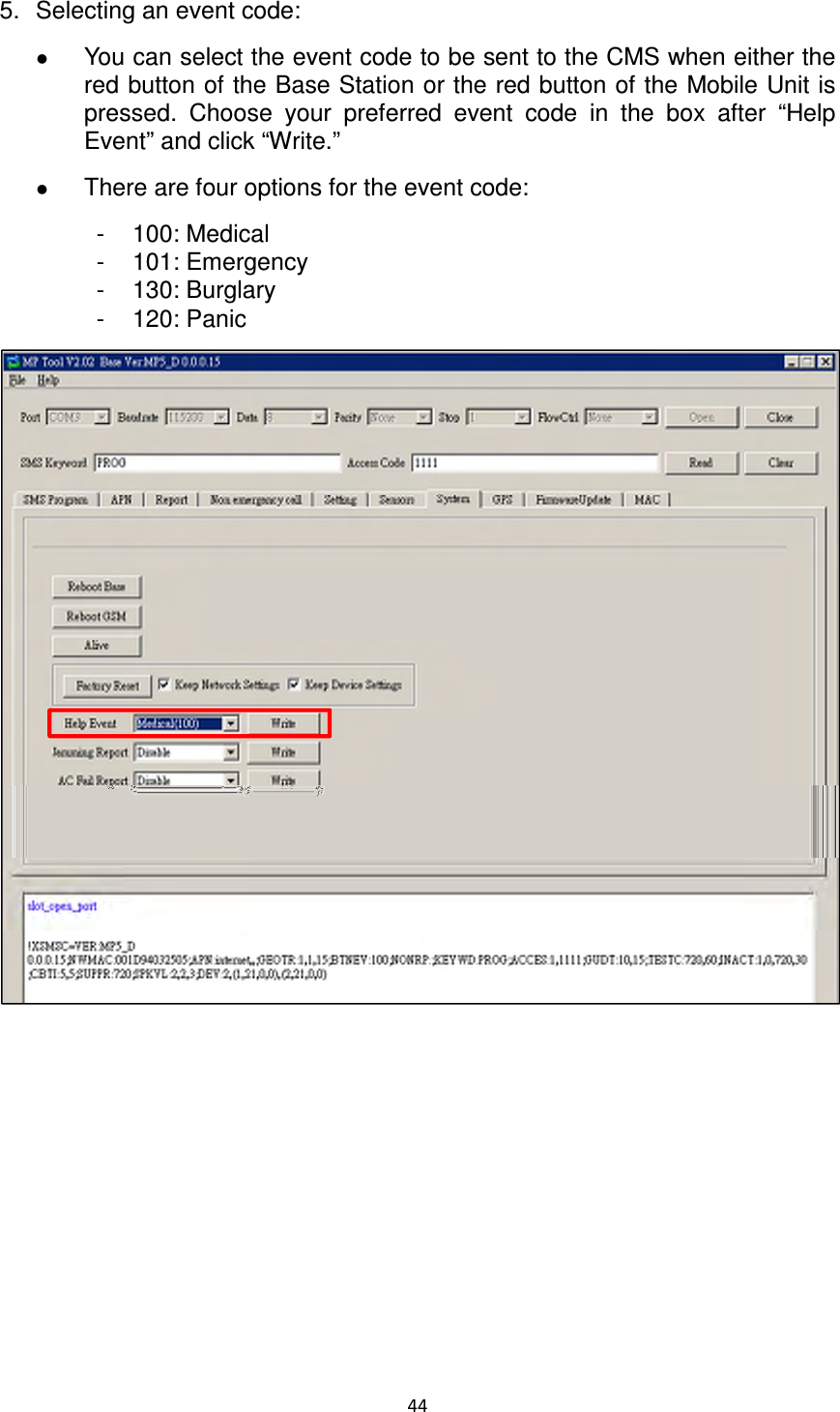
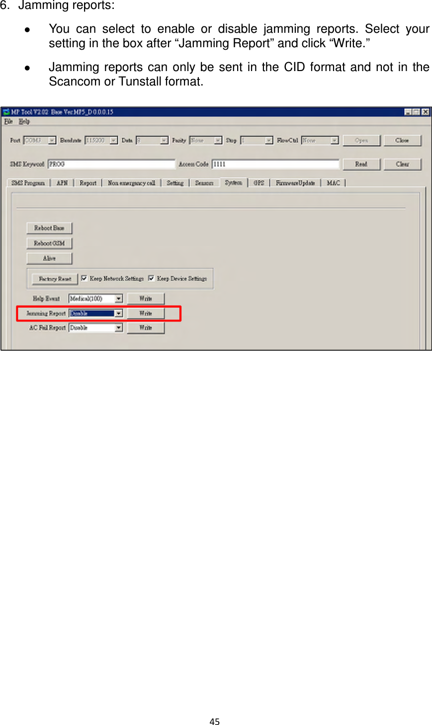
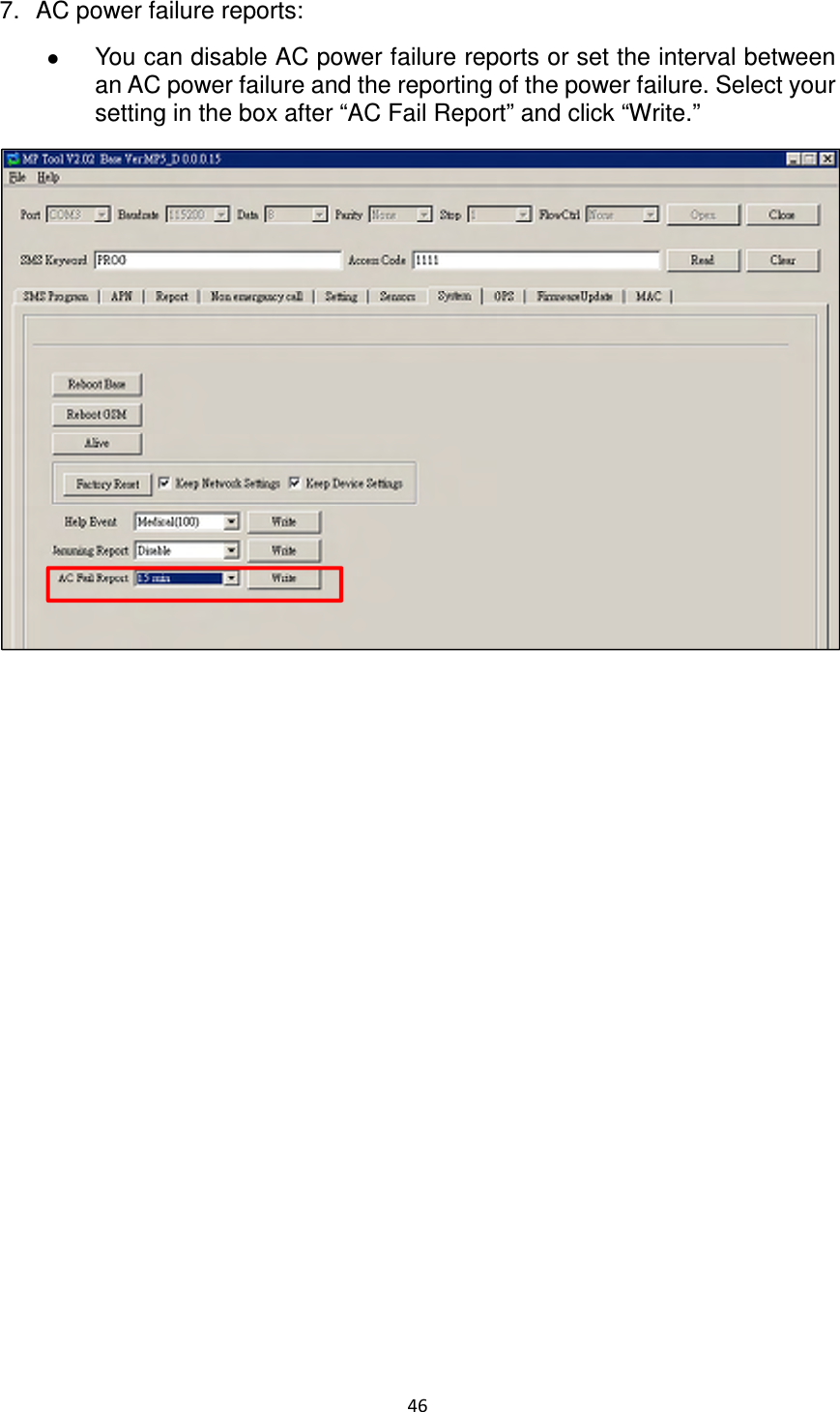
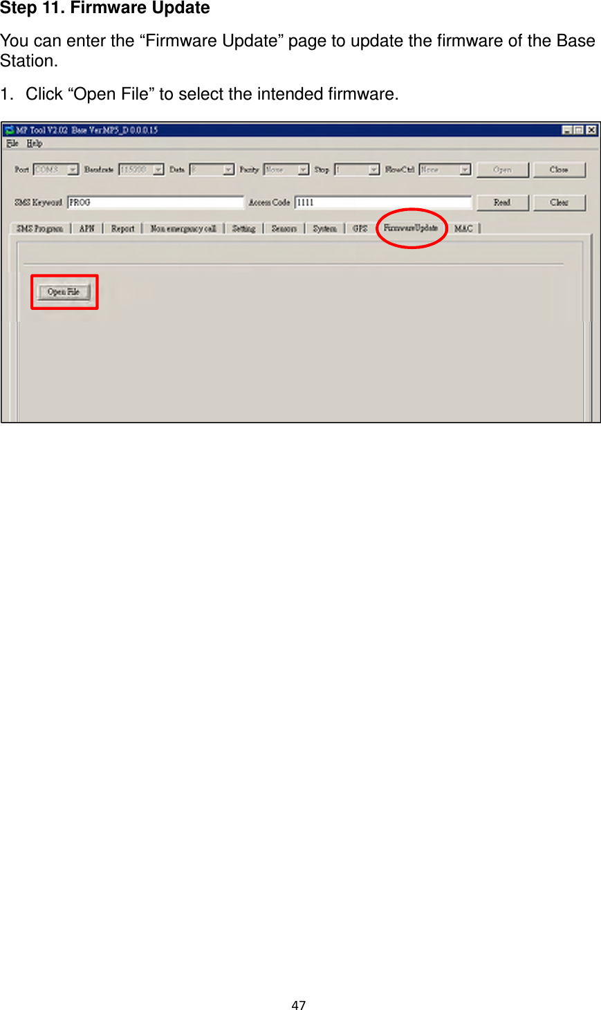
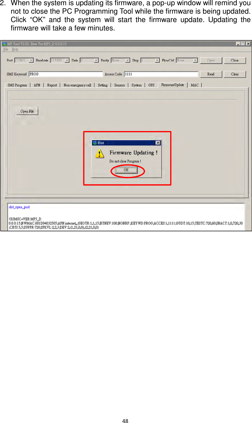
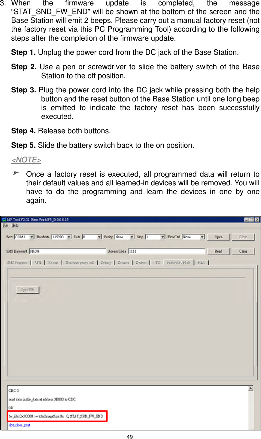
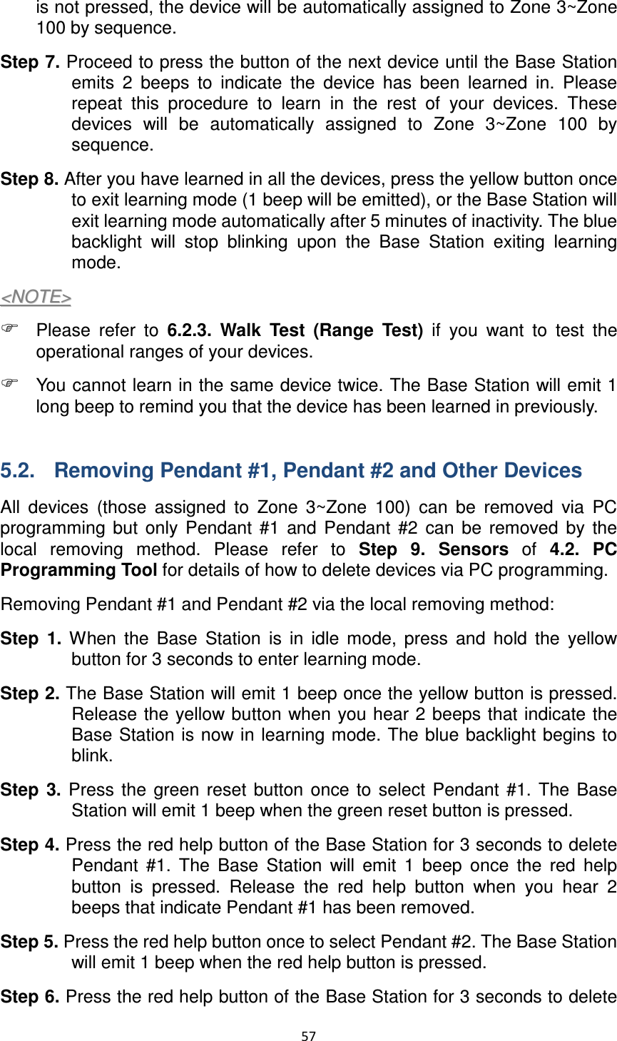
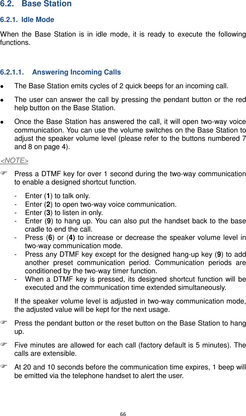
![36 16. Sound Setting Confirm Beep: Select “on” to enable confirmation beeps during reporting or “off” to disable confirmation beeps during reporting. 17. Answering Incoming [Calls]: When this function is set as “on,” the Base Station rings for incoming calls. You can answer an incoming call by pressing the red help button on the Base Station. When this function is set as “off,” the Base Station remains silent during incoming calls. Incoming calls will be directly hung up. 18. Alarm Length: Select the built-in siren duration when an alarm is activated. 19. Exit Time: Select the length of the exit time before your system enters armed mode upon your departure from home. 20. Entry Time: Select the length of the entry time before the system changes from armed mode to disarmed mode upon your arrival at home. <<NNOOTTEE>> The settings of “Alarm Length,” “Exit Time” and “Entry Time” are functional only when the yellow button on the Base Station is programmed as a security button.](https://usermanual.wiki/Climax-Technology-Co/MP/User-Guide-1999234-Page-39.png)