Climax Technology Co MX Wireless Medical Alarm System User Manual
Climax Technology Co Ltd Wireless Medical Alarm System Users Manual
UserManual.wiki
>
Climax Technology Co
>
MX User Manual
Users Manual
Navigation menu
Upload a User Manual
Namespaces
Wiki Guide
HTML
PDF
Info
Views
User Manual
Discussion / Help
Navigation
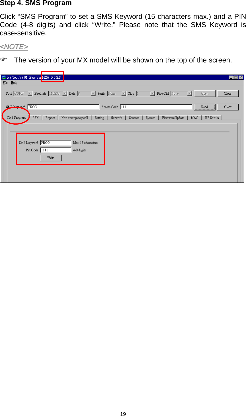

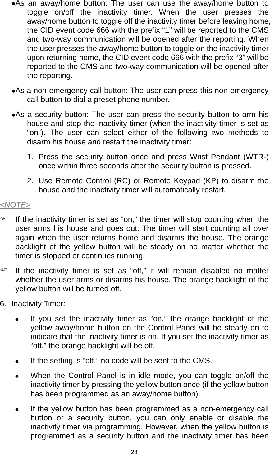
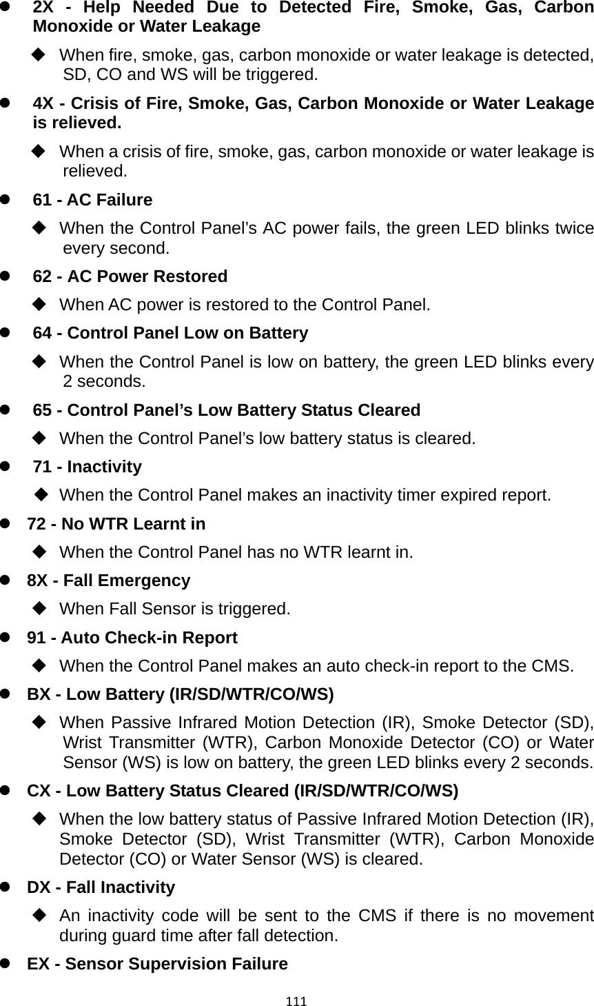
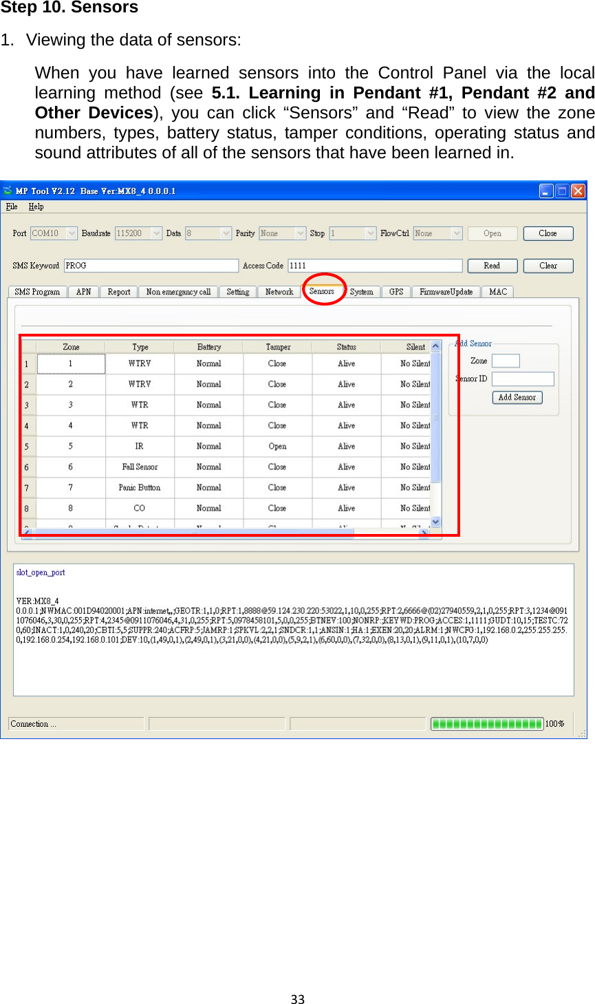
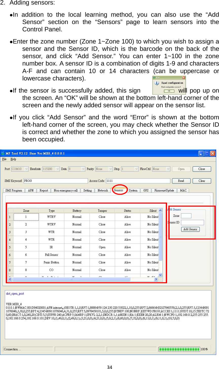
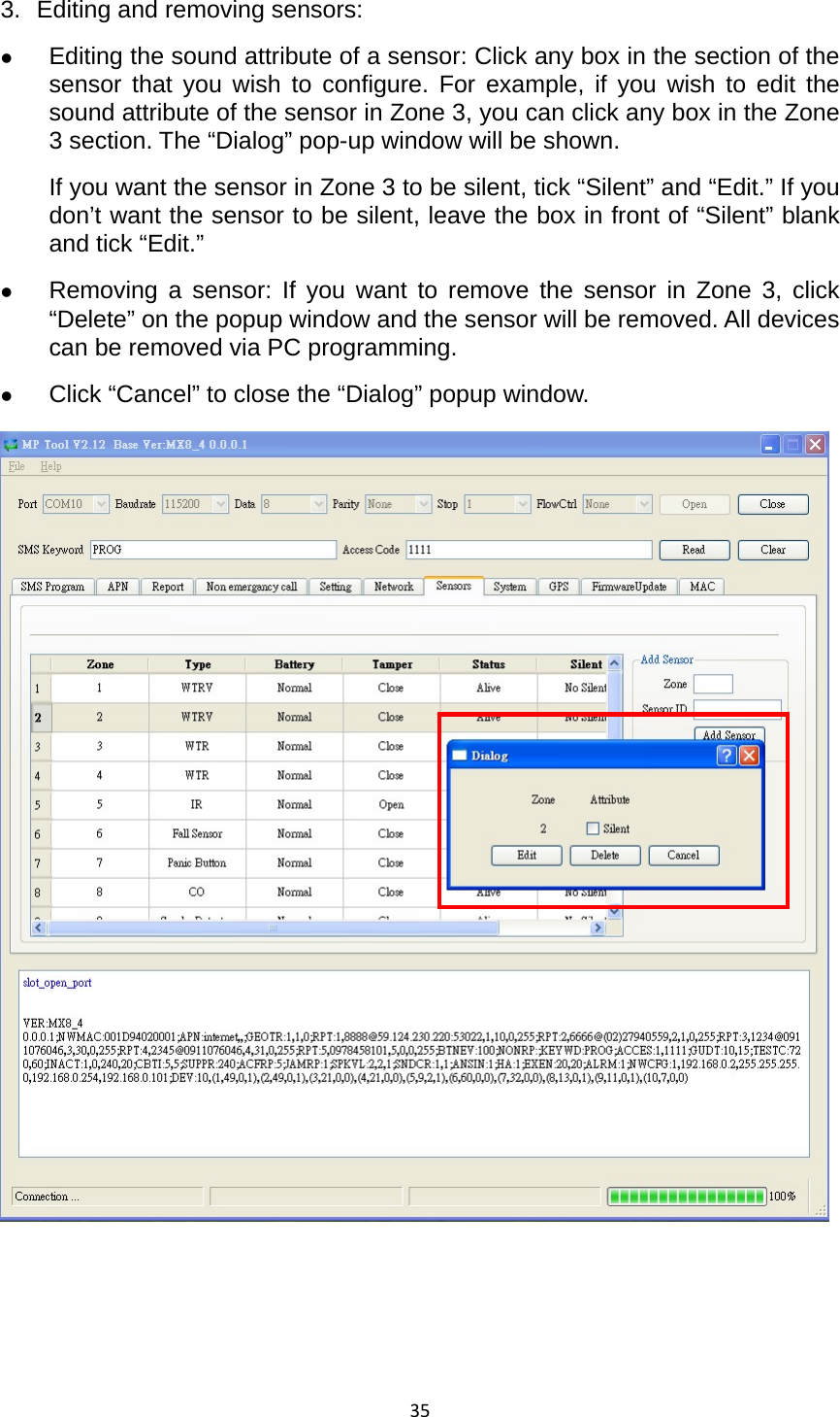
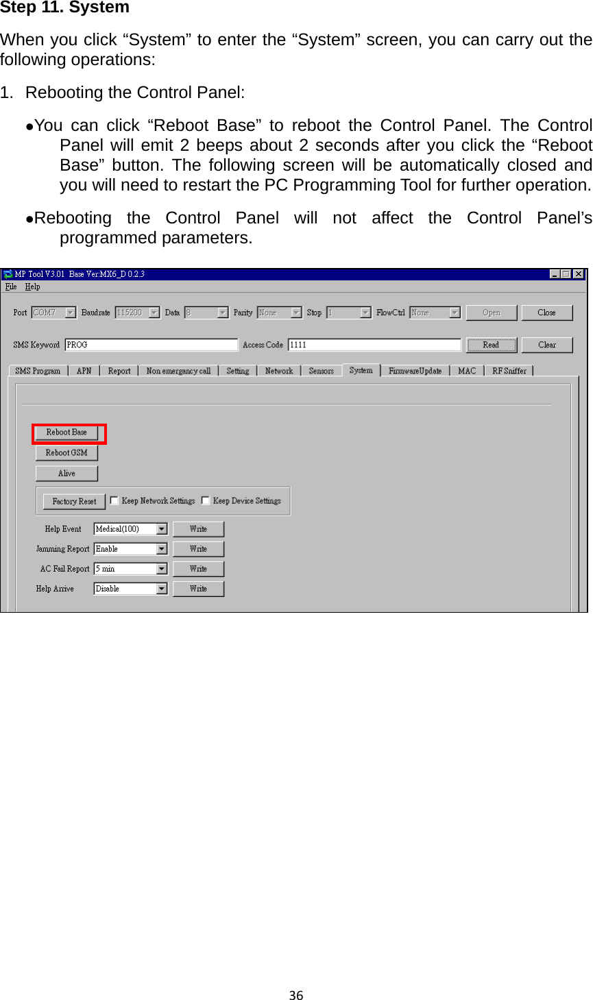
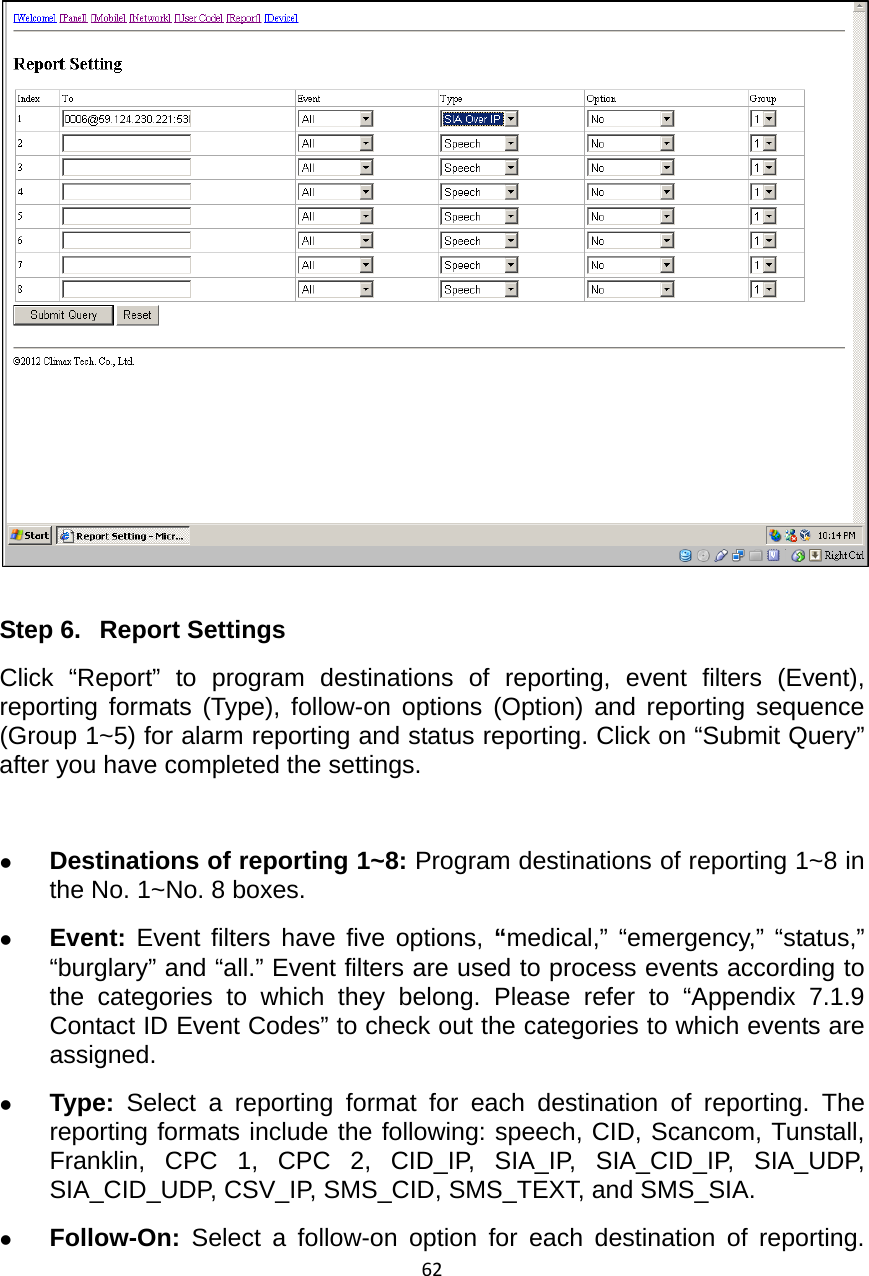
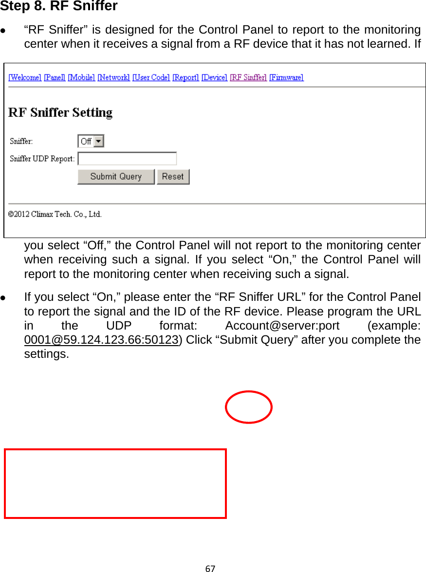
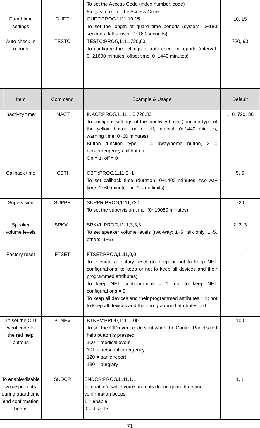
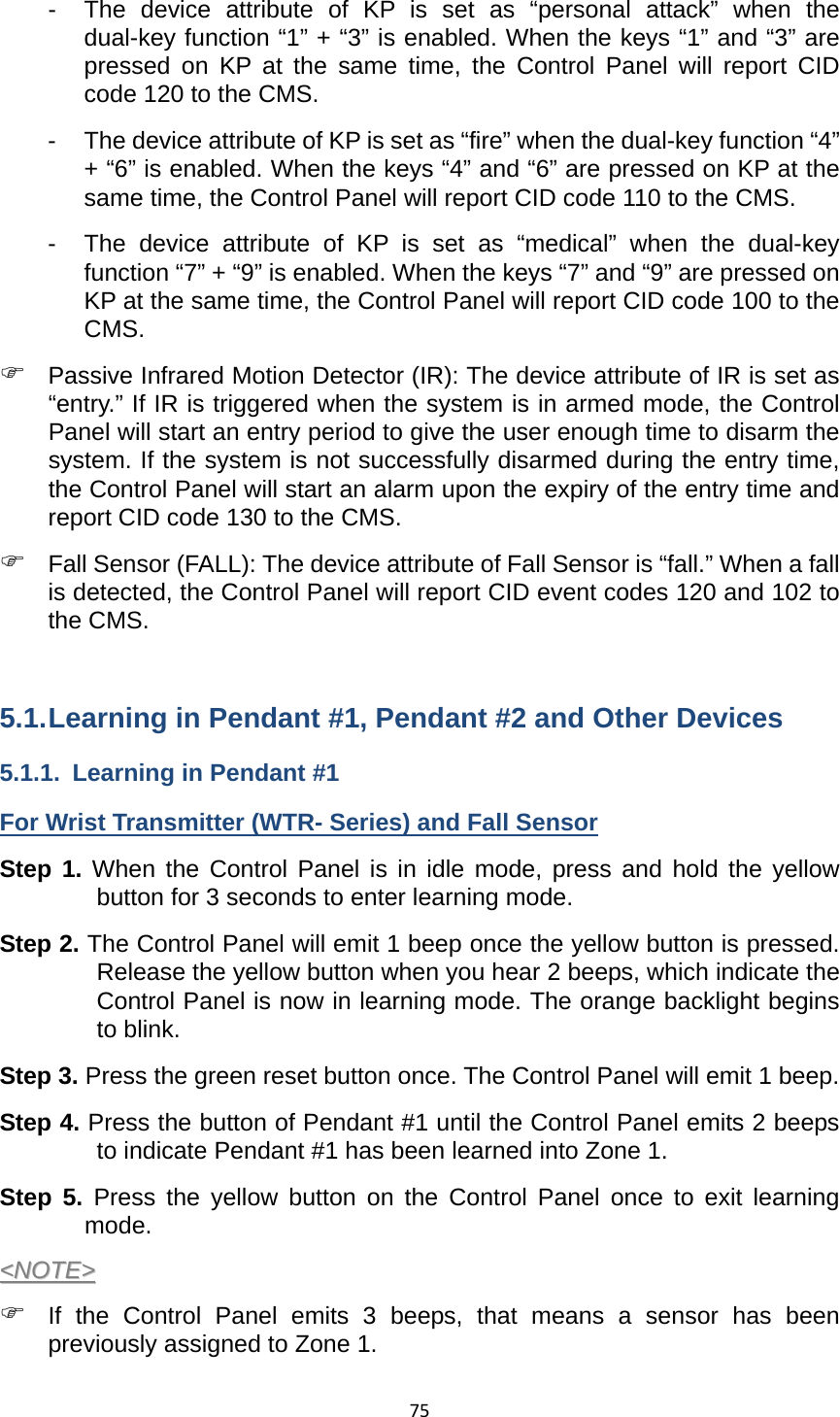
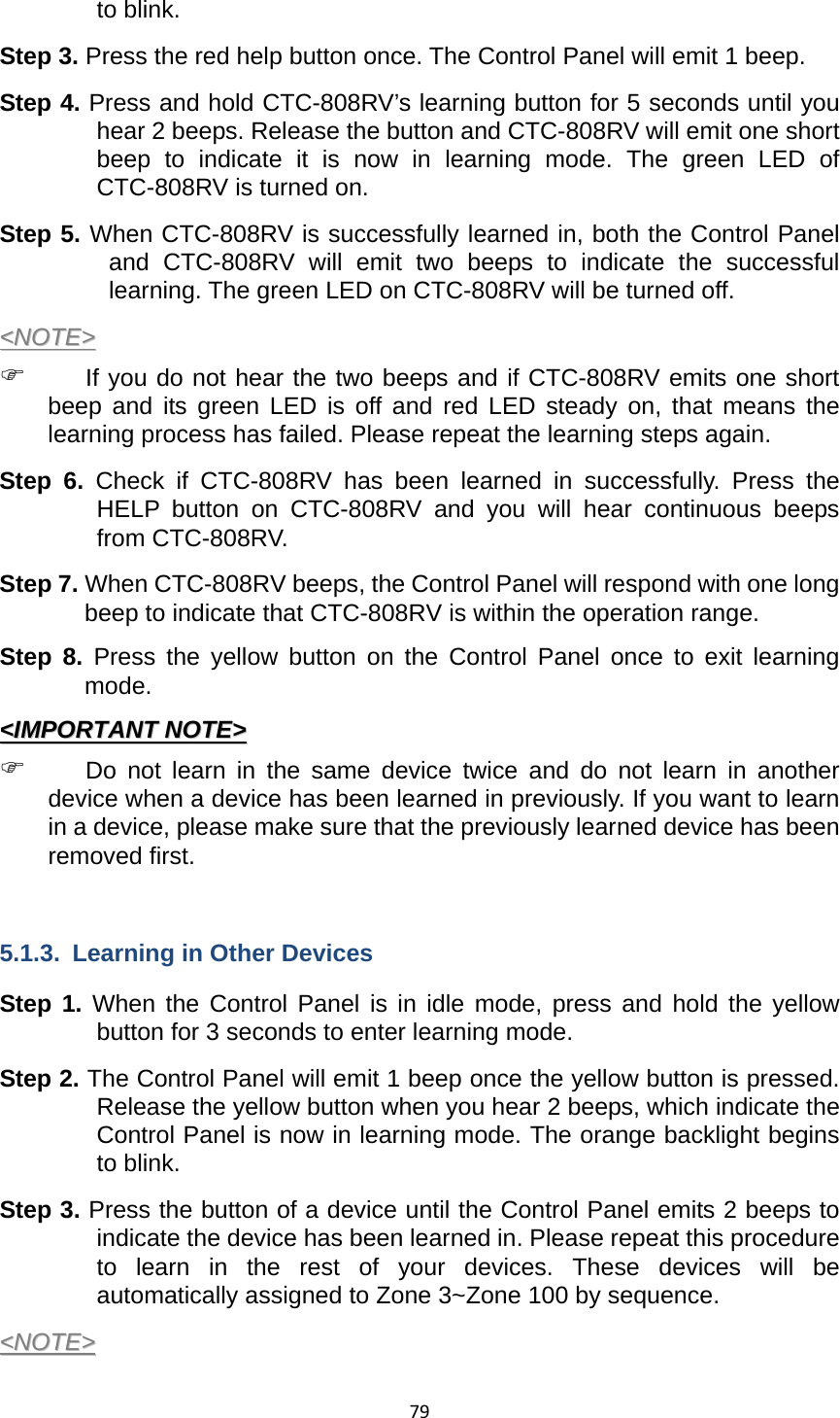
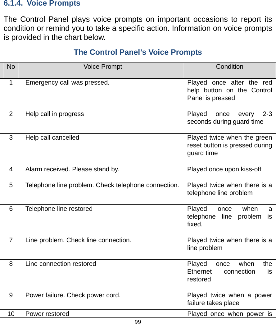
![31beeping sound during guard time. 16. Sound Setting Confirm Beep: z Select “on” to enable confirmation beeps during reporting or “off” to disable confirmation beeps during reporting. 17. Answering Incoming [Calls]: z When this function is set as “on,” the Control Panel rings for incoming calls. You can answer an incoming call by pressing the red help button on the Control Panel. z When this function is set as “off,” the Control Panel remains silent during incoming calls. Incoming calls will be directly hung up. 18. Alarm Length: z Select the built-in siren duration when an alarm is activated. 19. Exit Time: z Select the length of the exit time before your system enters armed mode upon your departure from home. 20. Entry Time: z Select the length of the entry time before the system changes from armed mode to disarmed mode upon your arrival at home. <<NNOOTTEE>> ) The settings of “Alarm Length,” “Exit Time” and “Entry Time” are functional only when the yellow button on the Control Panel is programmed as a security button.](https://usermanual.wiki/Climax-Technology-Co/MX/User-Guide-2102749-Page-34.png)
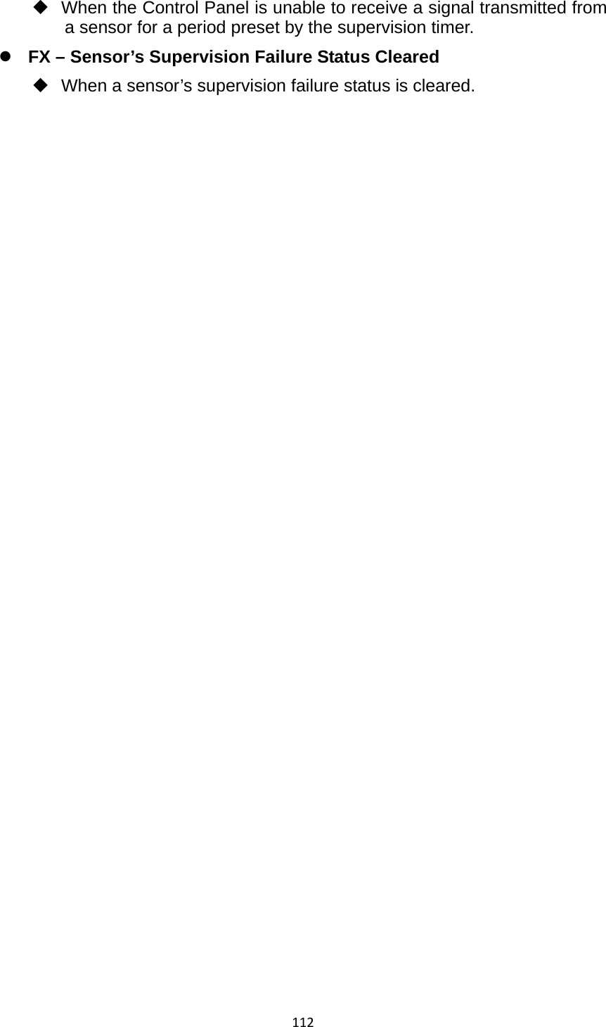
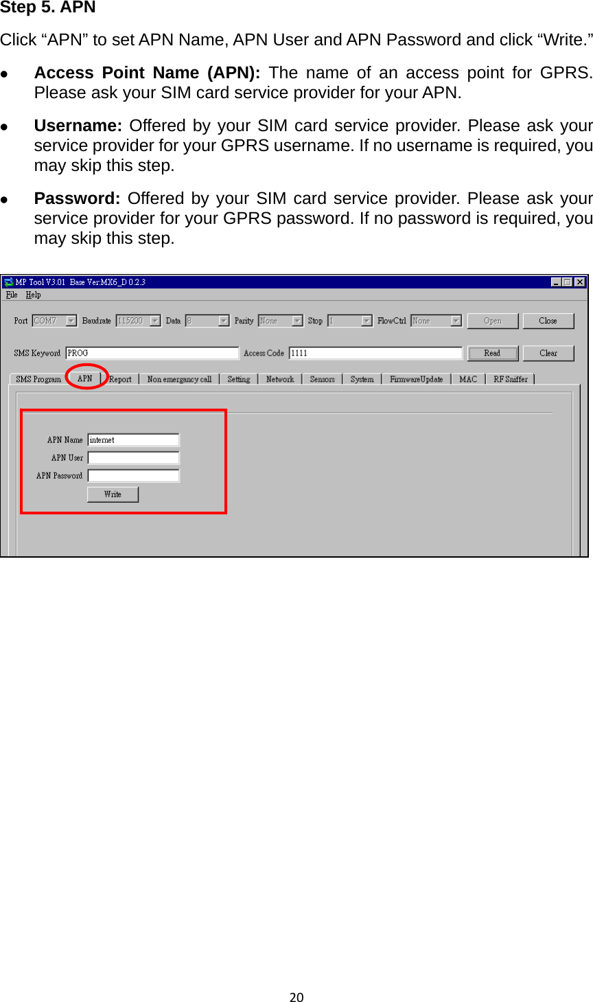
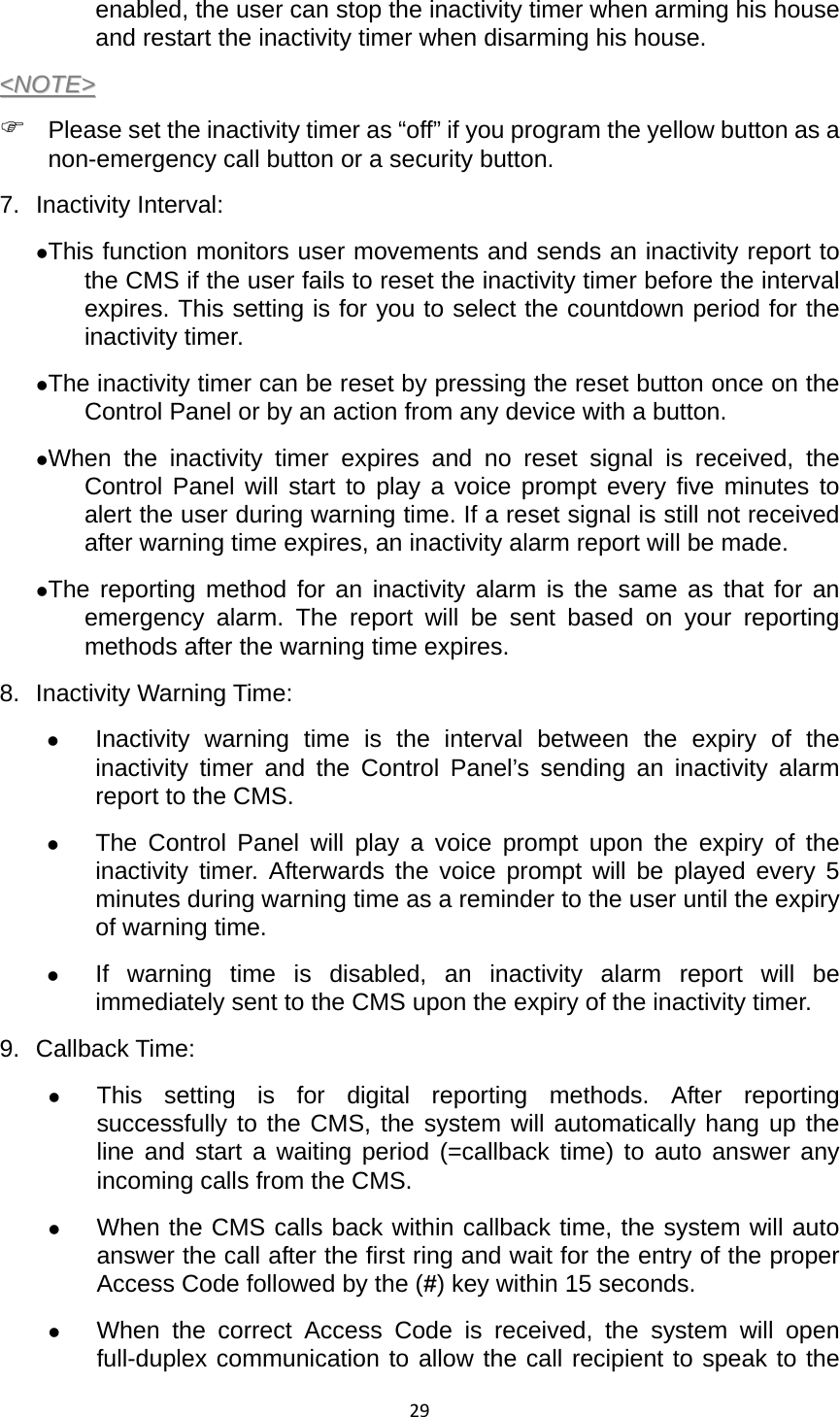
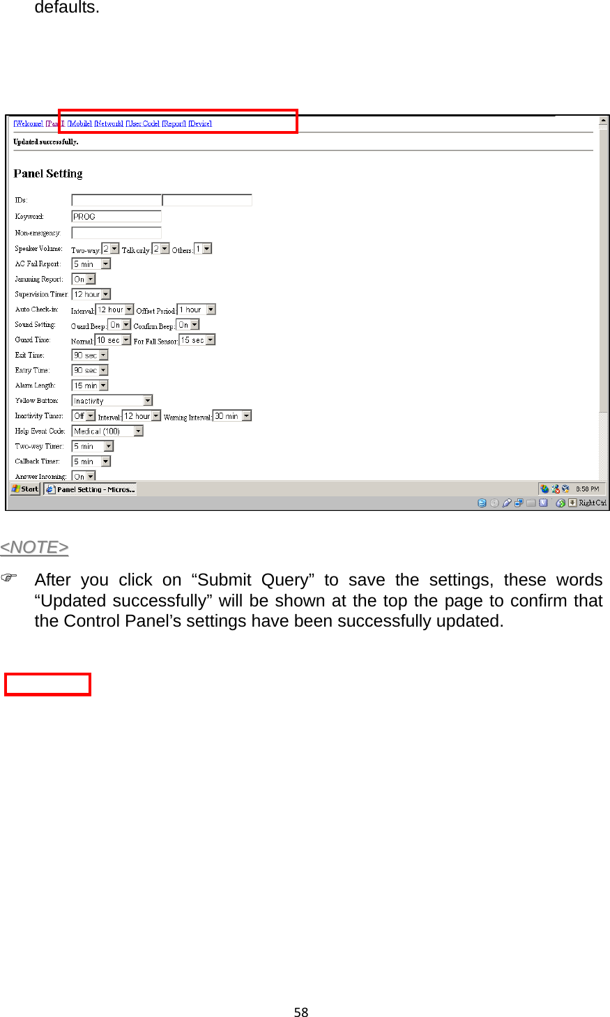
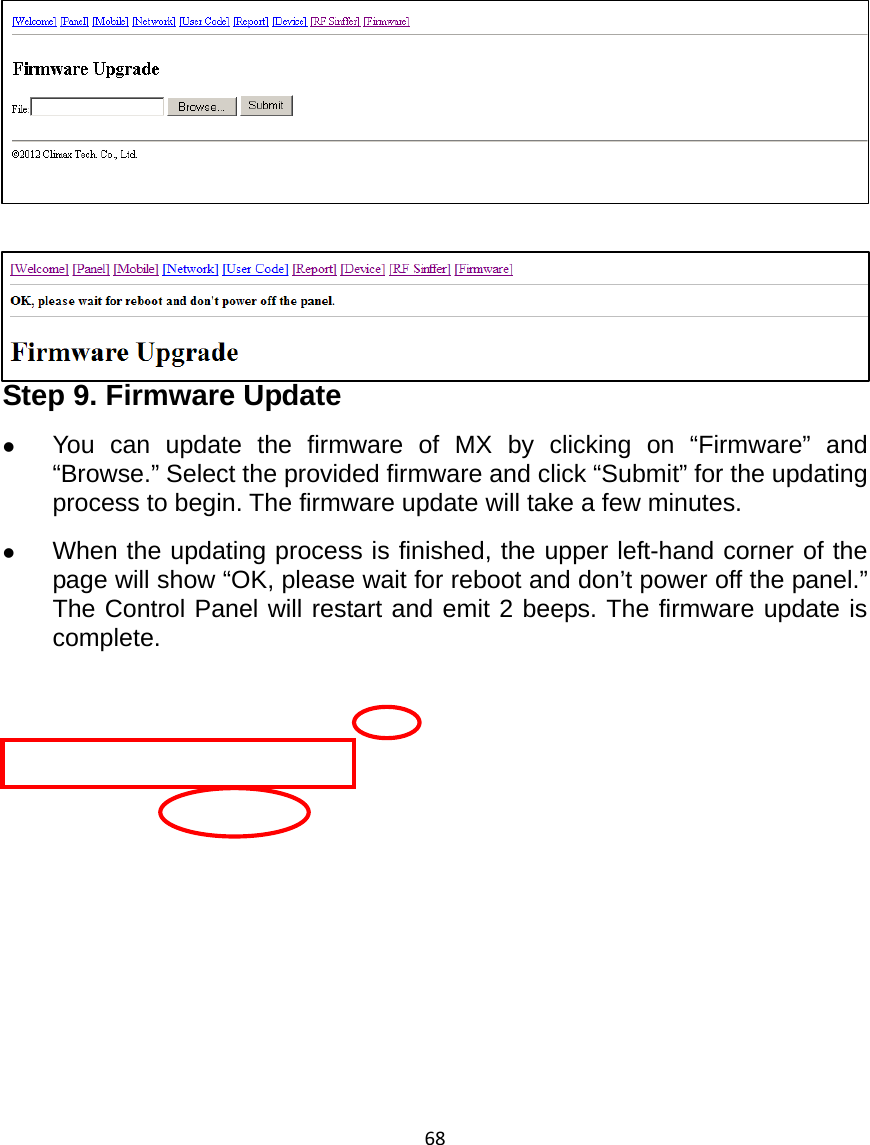
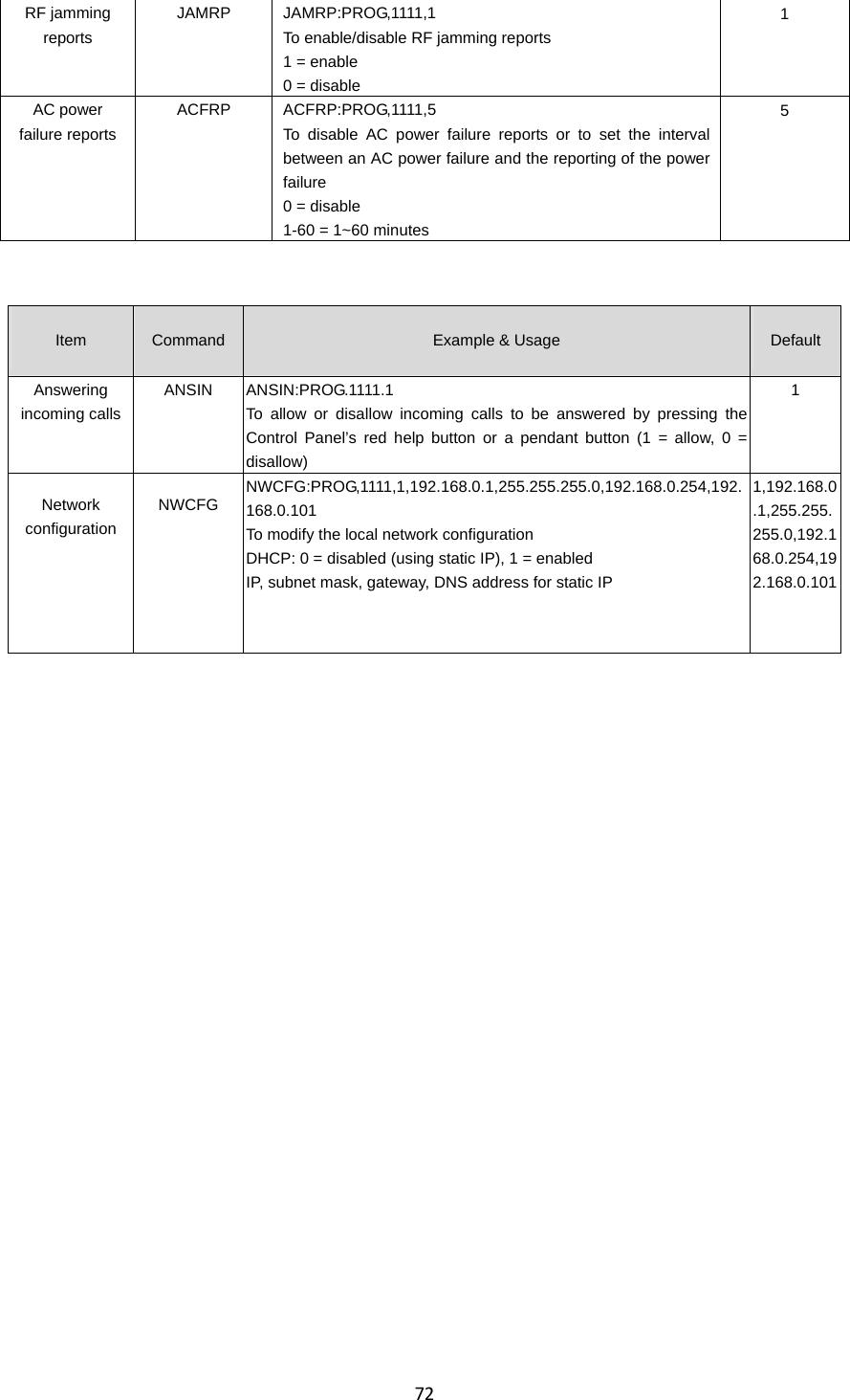
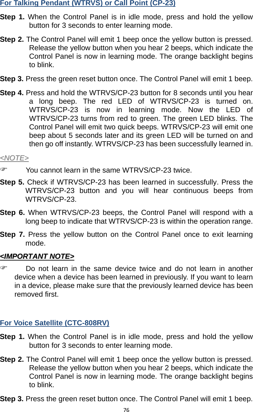
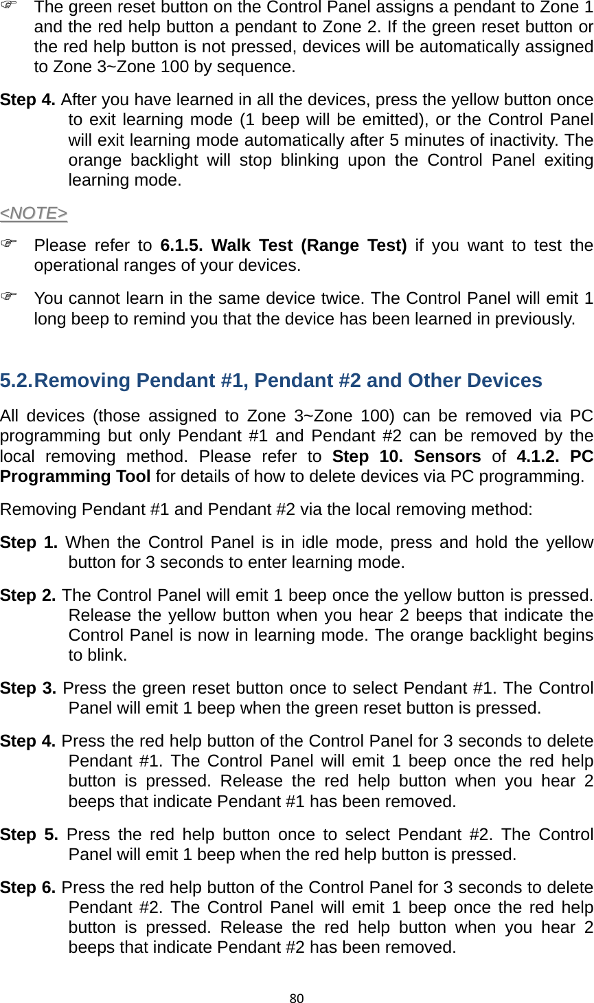
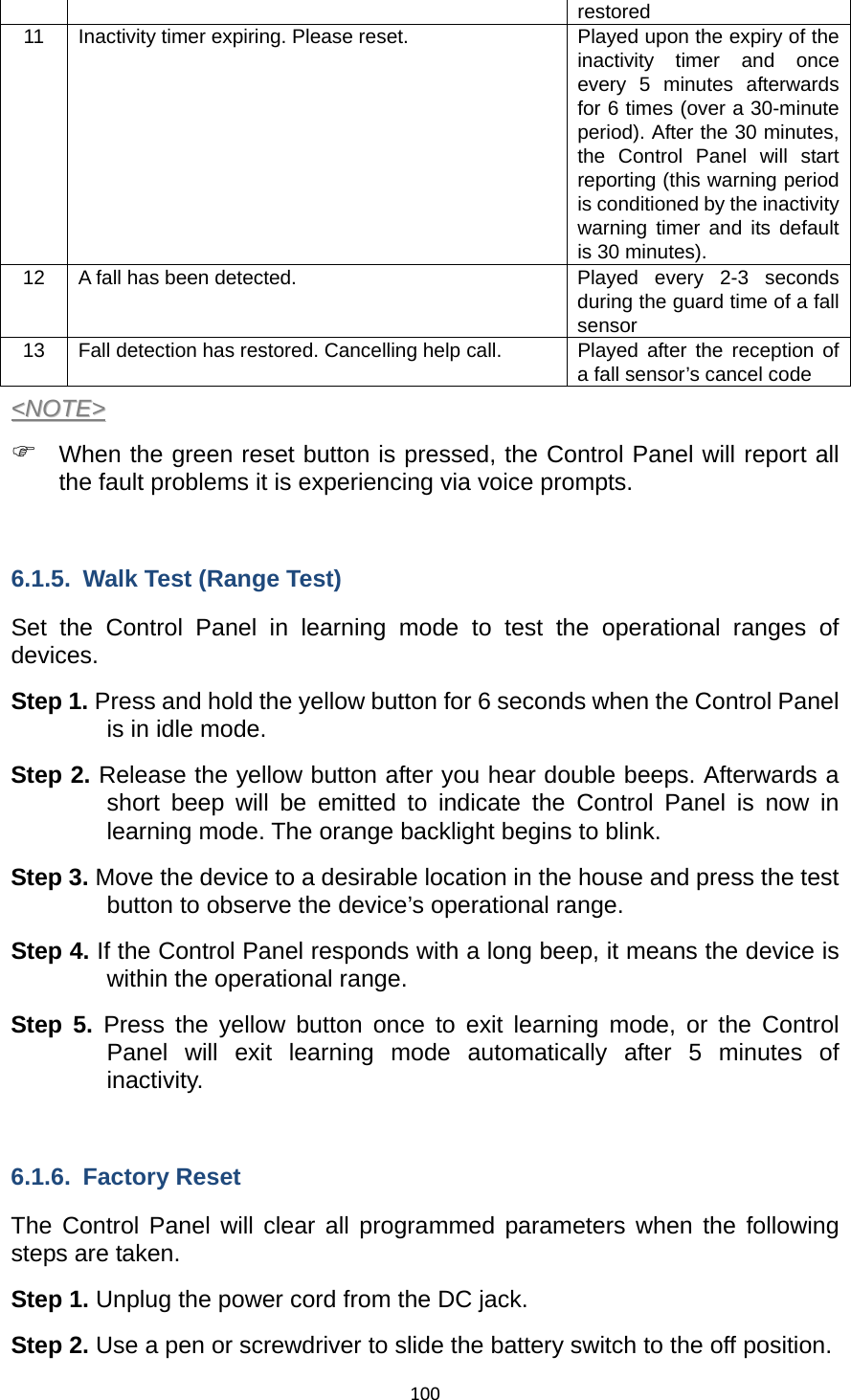
![57failure period. 19. Answering Incoming [Calls]: z When this function is set as “On,” the Control Panel rings for incoming calls. You can answer an incoming call by pressing the red help button on the Control Panel. z When this function is set as “Off,” the Control Panel remains silent during incoming calls. Incoming calls will be directly hung up. 20. Help Arrive: Select “On” to enable the help/nurse arrival function or “Off” to disable the help/nurse arrival function. 21. Reset: z You can click on the “Reset” button at the bottom of the page (shown in the picture below) to reboot the Control Panel. The Control Panel will emit 2 beeps about 2 seconds after you click the “Reset” button. z Rebooting the Control Panel will not affect the Control Panel’s programmed parameters. <<NNOOTTEE>> ) PPlleeaassee cclliicckk oonn tthhee ““RReesseett”” bbuuttttoonn aass mmaarrkkeedd bbeellooww ttoo rreebboooott tthhee CCoonnttrrooll PPaanneell.. TThhee ““RReesseett”” bbuuttttoonn nneexxtt ttoo tthhee ““SSuubbmmiitt QQuueerryy”” bbuuttttoonn iiss uusseedd ttoo rreessttoorree sseettttiinnggss oonn tthhiiss ppaaggee ttoo ddeeffaauulltt vvaalluueess.. 22. Factory Reset: z You can click on “Factory Reset” to restore the system to factory settings. The system will immediately restore all programmed parameters to factory settings and the Control Panel will emit 2 beeps after you click the “Factory Reset” button. z If you want to keep your network settings and/or device settings, please click the box(s) before these specifications before clicking “Factory Reset.” Your network settings and/or device settings will then be preserved while other programmed parameters are restored to factory](https://usermanual.wiki/Climax-Technology-Co/MX/User-Guide-2102749-Page-60.png)

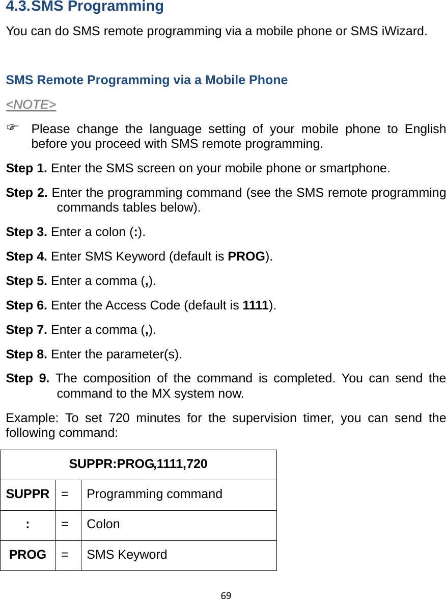
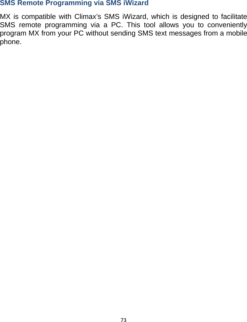
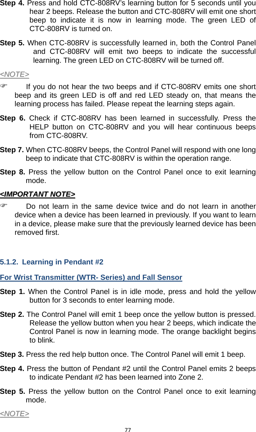
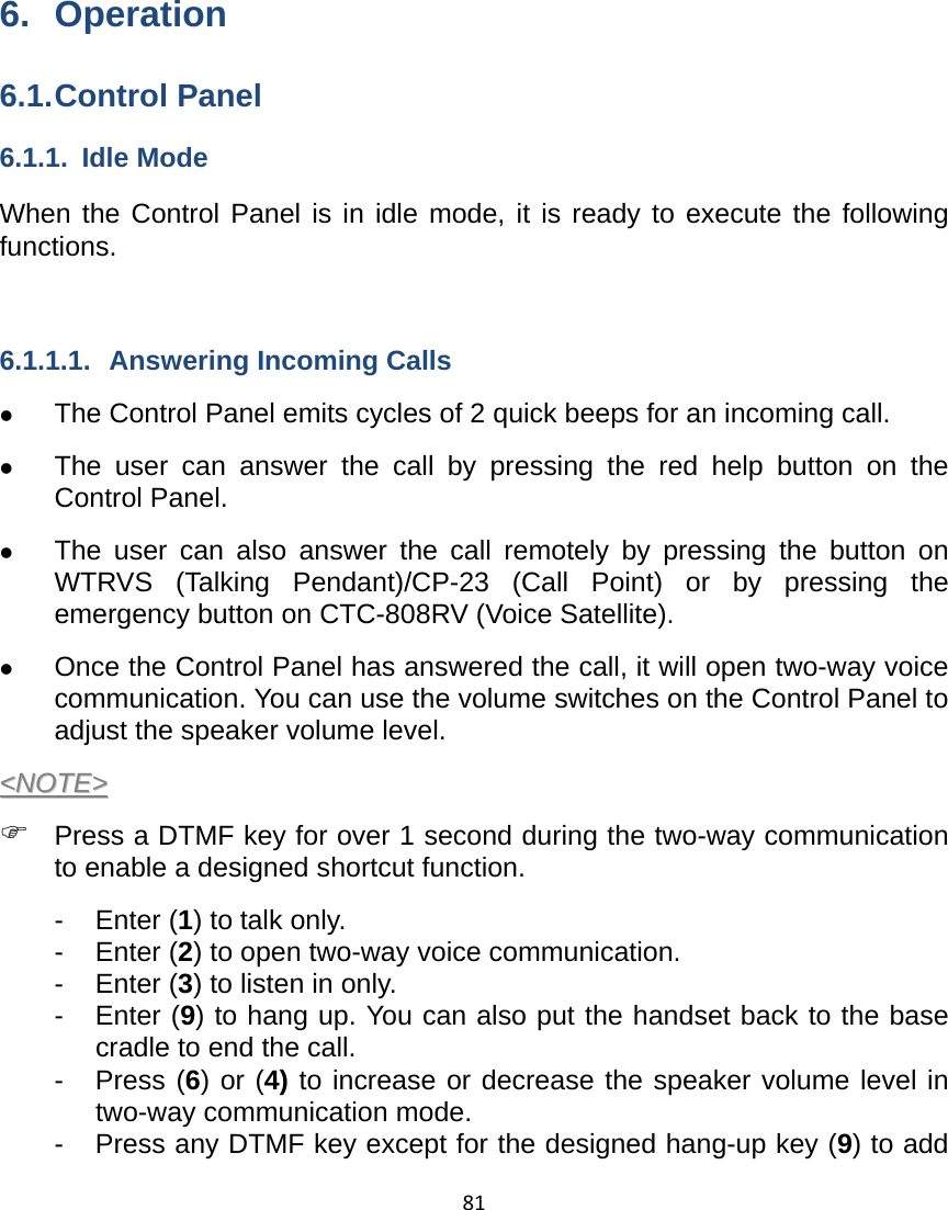
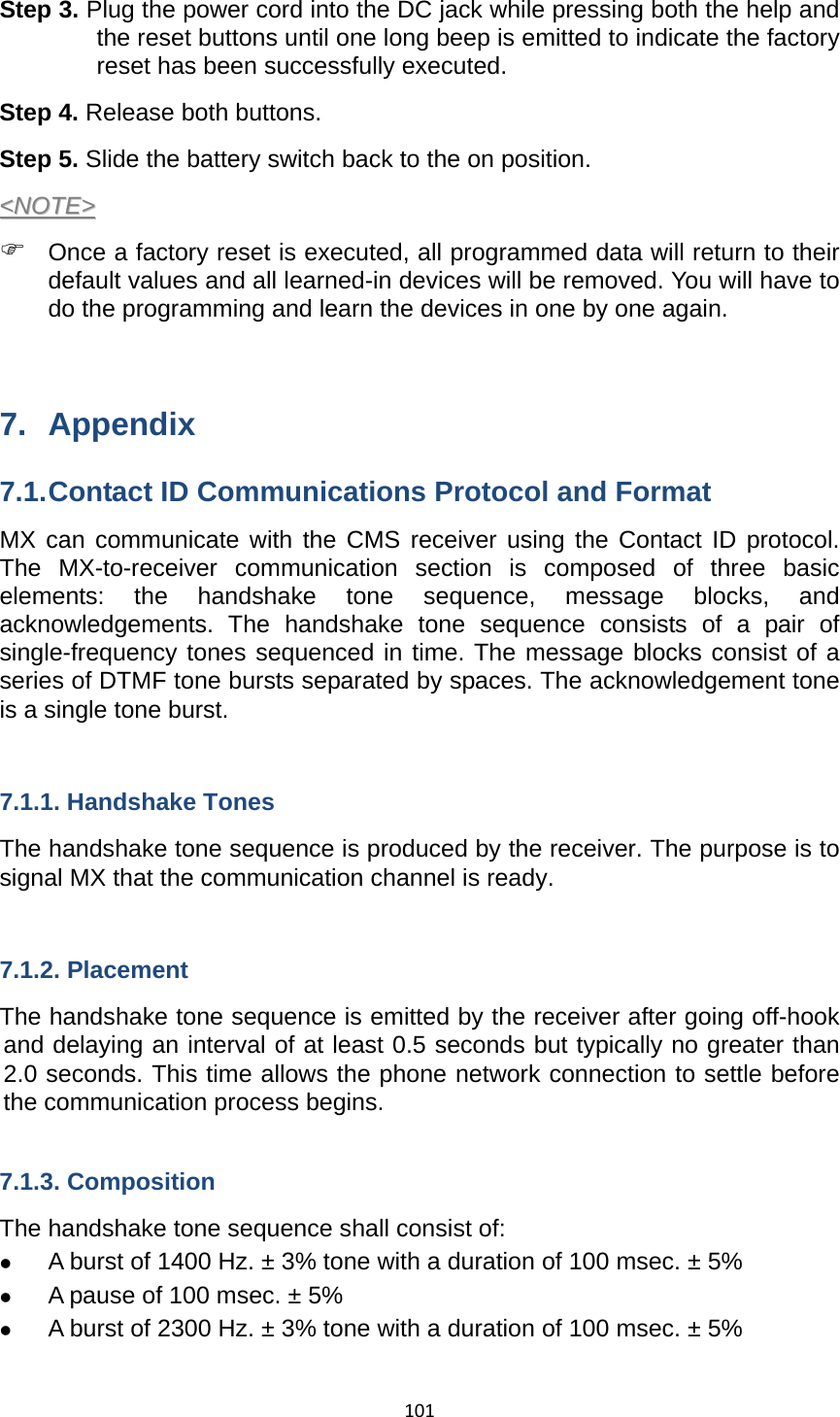
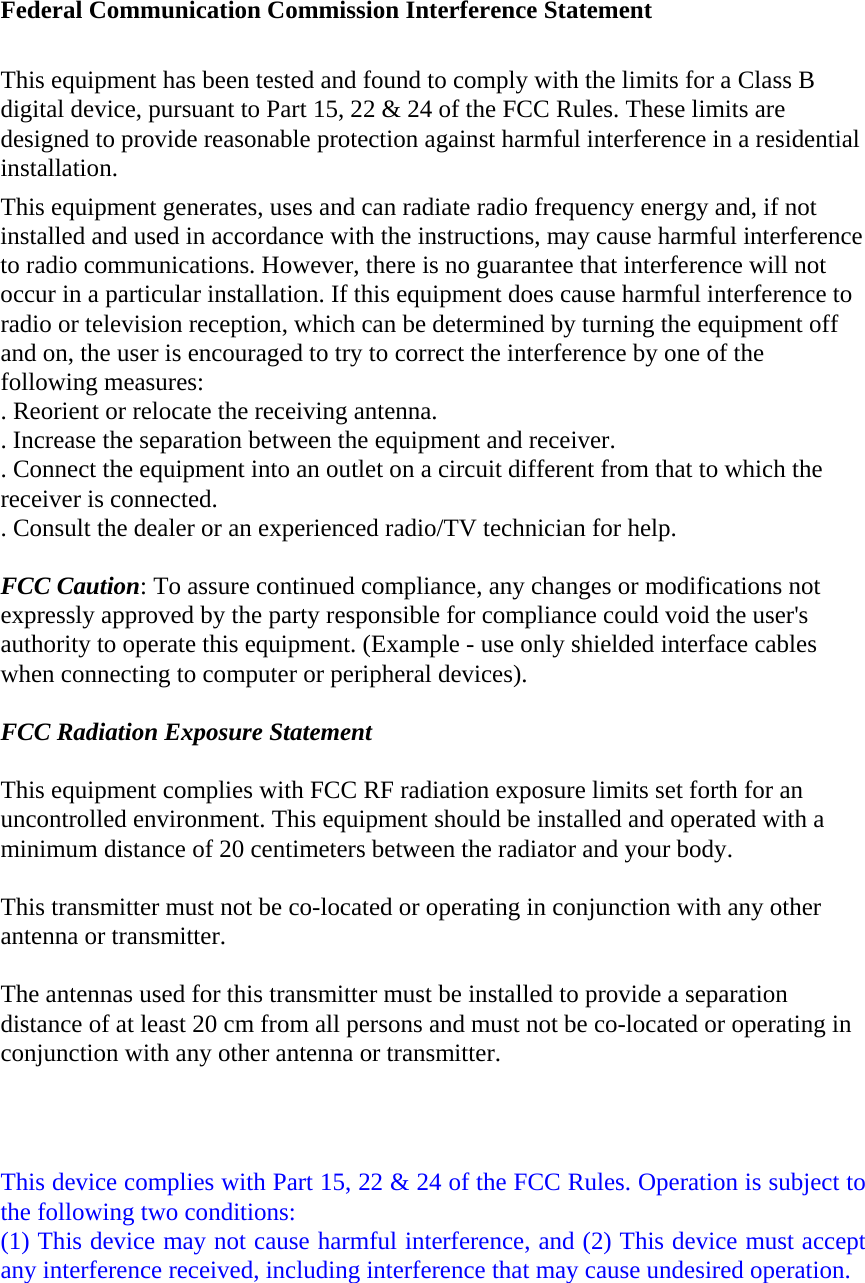
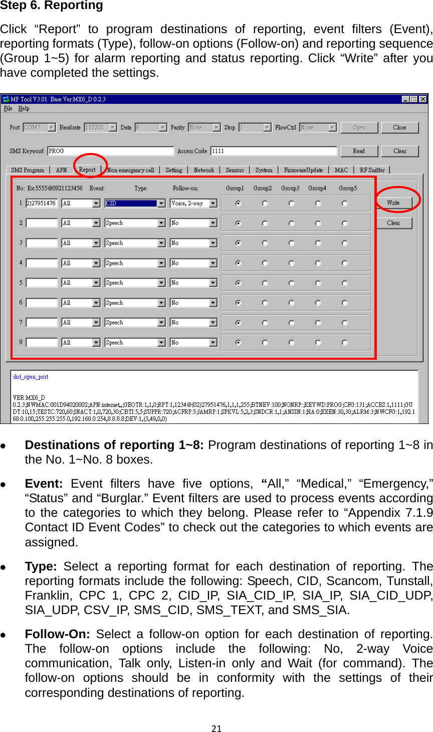
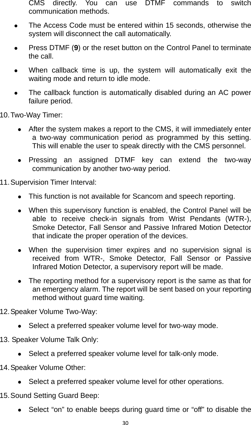
![105 When the Control Panel makes an inactivity timer expired report. <<NNOOTTEE>> ) This event code will be sent with fixed zone number 072. z 661 – Nurse or Help Has Arrived/Nurse’s Job Completed (medical) When the green reset button on the Control Panel is pressed to signal that a nurse or help has arrived (1-661). When the green reset button on the Control Panel is pressed to signal that the nurse’s job has been completed (3-661). z 662 – Help Still Needed (medical) When the red help button on the Control Panel is pressed to signal that help is still needed. z 663 – Case Closed by the Nurse (medical) When the green reset button on the Control Panel is pressed twice quickly to signal that the nurse closes the emergency case because the user actually has no problem. z 665 – User Check-in/Check-out (status) When the user presses the yellow button (programmed as a check-in/out button) on the Control Panel to check in or check out. z 666 – Away/Home (status) When the user presses the yellow button (programmed as an away/home button) on the Control Panel upon leaving home or returning home. Two-way communication will be opened between the Control Panel and the CMS after this event code is reported to the CMS. 7.2. SIA Digital Communication Standard Please refer to the document “SIA Digital Communication Standard – Internet Protocol Event Reporting (ANSI/SIA DC-09-2012A)” published by the Security Industry Association for details. An example of an event reported in the SIA/CID format is as follows: <0A><61><A4>004D"ADM-CID"0033L0#9999[#9999|1100 00 000][X121E35.057831][Y25N03.900375][P2772]<0D> Where: z “ADM-CID” means that the content of this message is in the CID format. z 0033 for <seq> z L0 for <Lpref> z #9999[#9999|1100 00 000] 9999 = account number](https://usermanual.wiki/Climax-Technology-Co/MX/User-Guide-2102749-Page-108.png)
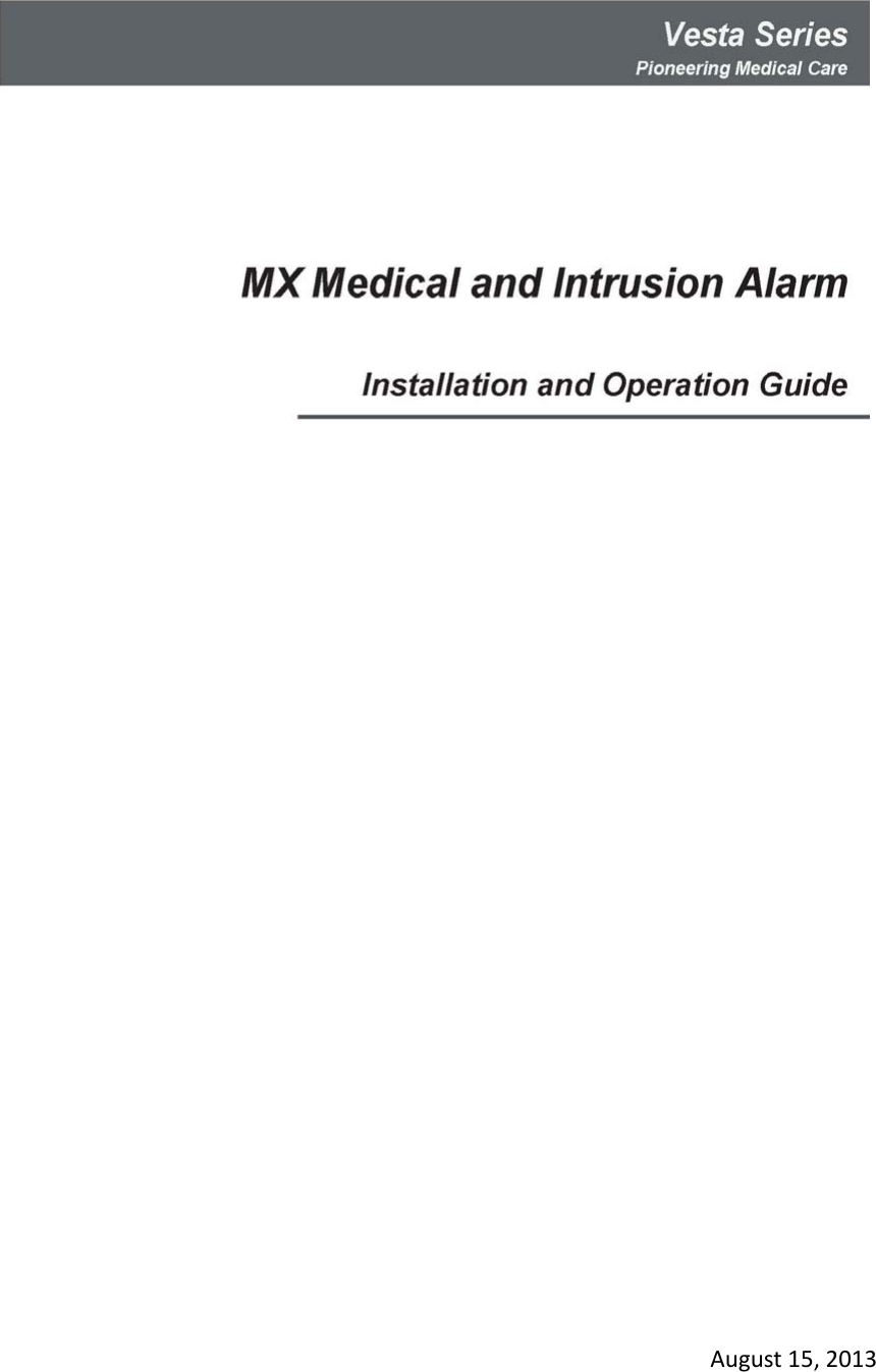
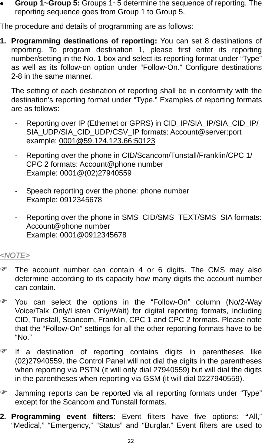
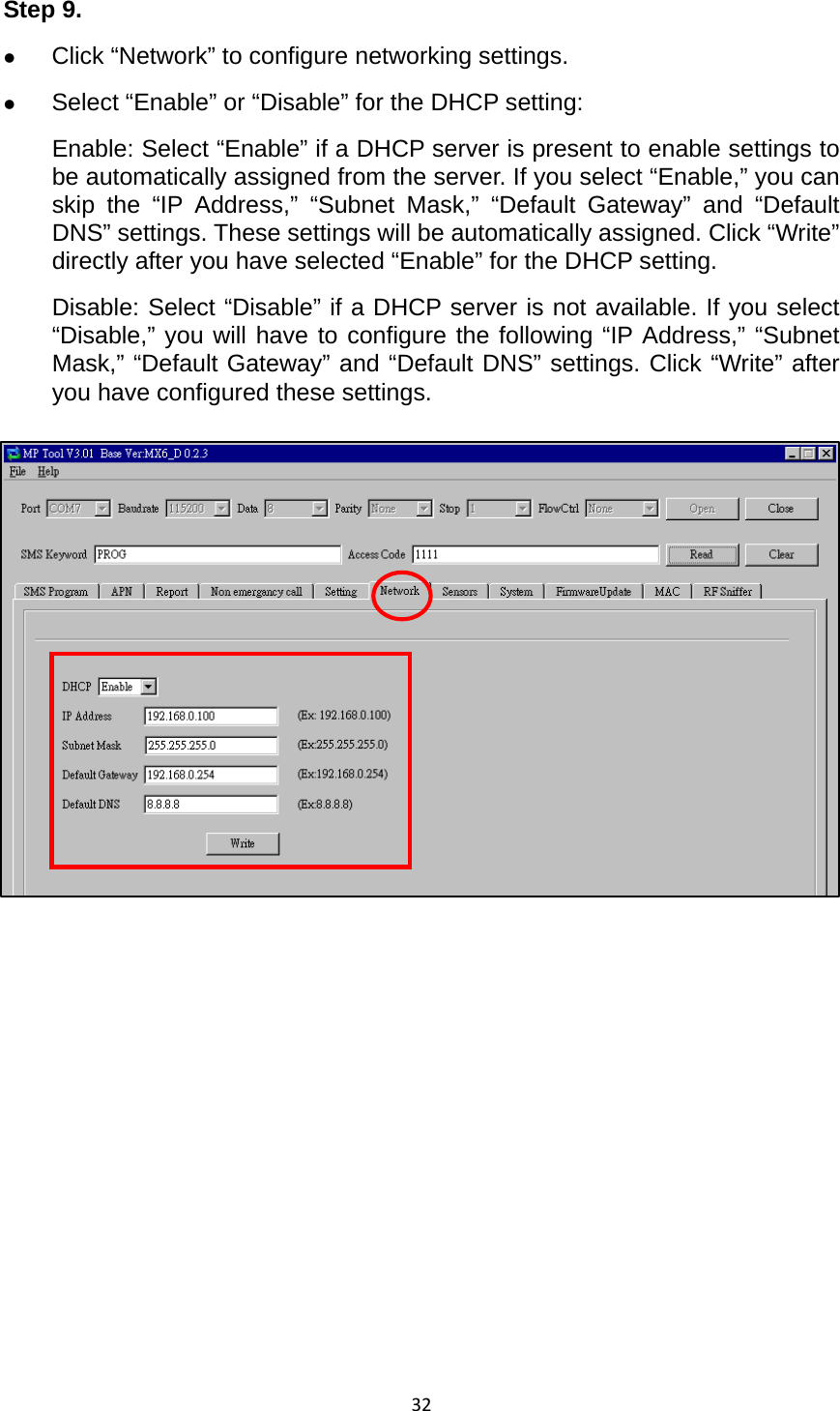
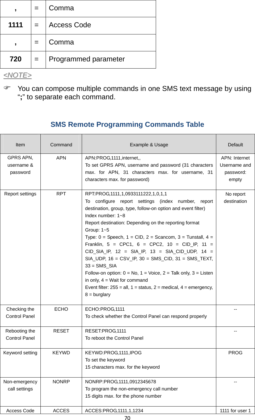
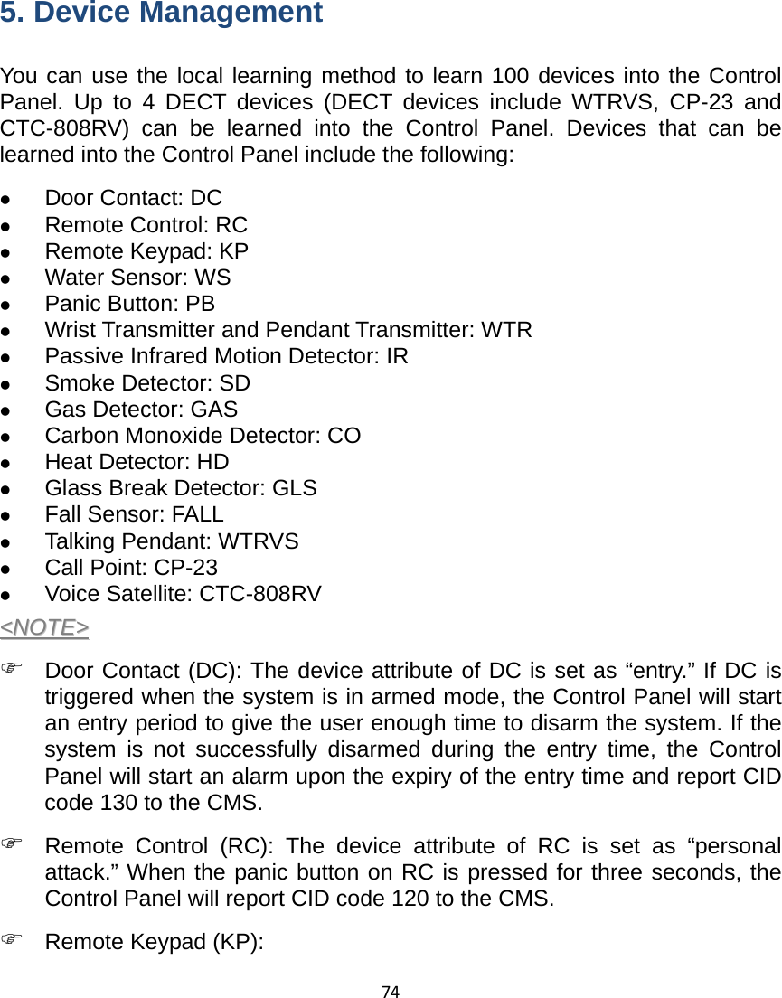
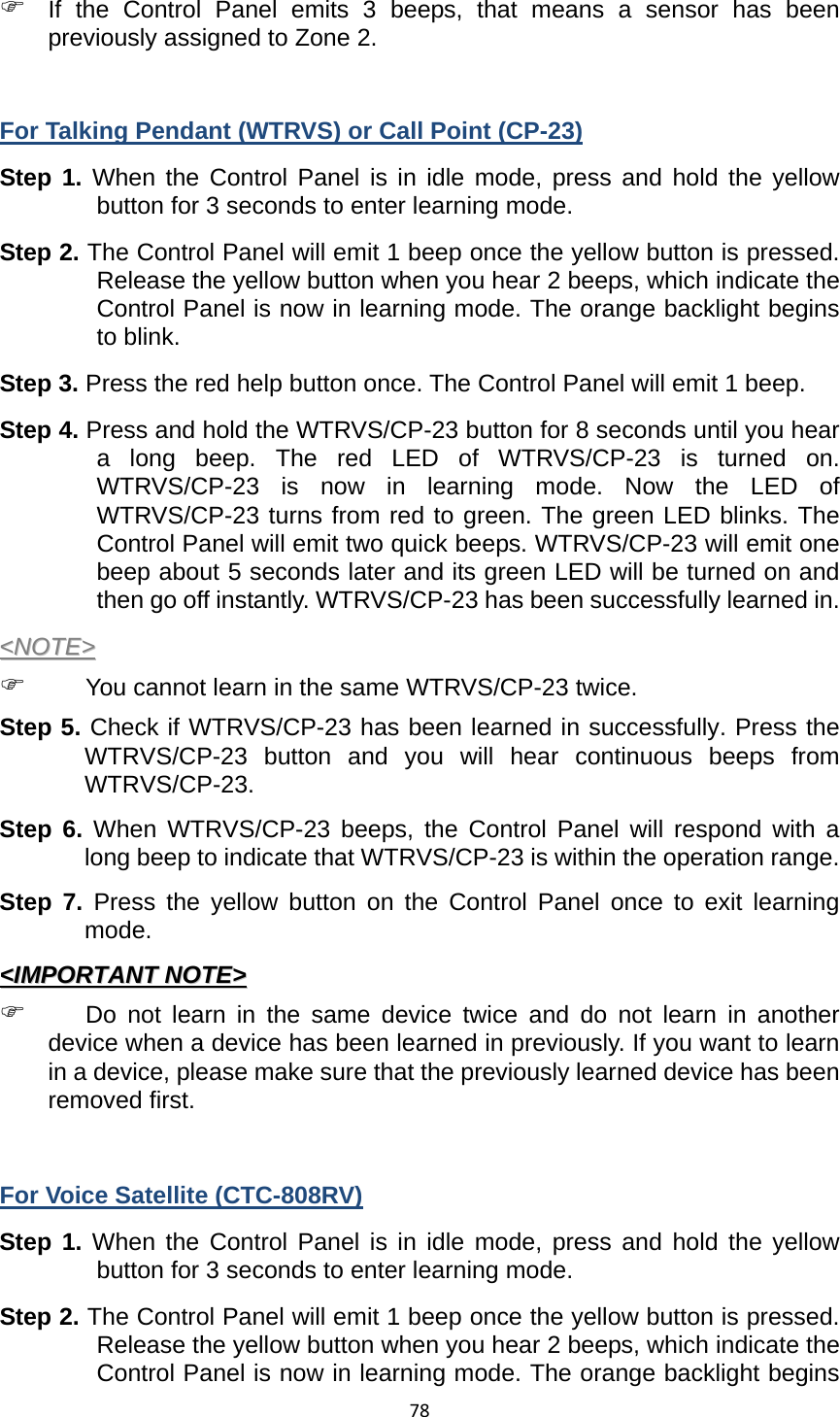
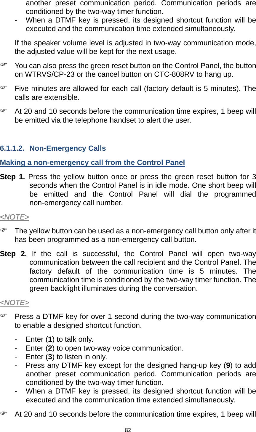
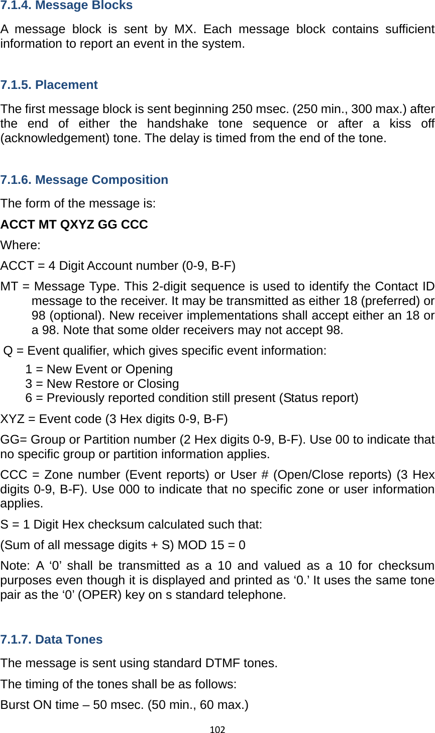
![1061100 00 000 = CID data (QXYZGGCCCC) z [X...] and [Y...] are location data. z [P...] stands for the margin of error of cell location. 7.3. Scancom Event Codes z 515555517 - Control Panel Emergency/Pendant #1 Emergency/Fall Emergency/WTR Emergency/PB Emergency (when two-way mode is set for follow-on operation) When the red help button on the Control Panel is pressed. When Pendant #1 is pressed or triggered. When Fall Sensor is pressed or triggered. When WTR (Pendant #1) or PB is pressed. z 515555557 - Control Panel Emergency/Pendant #1 Emergency/WS Emergency/Fall Emergency/WTR Emergency/PB Emergency (when two-way mode is not set for follow-on operation) When the red help button on the Control Panel is pressed. When Pendant #1 is pressed or triggered. When Water Sensor is triggered. When Fall Sensor is pressed or triggered. When WTR (Pendant #1) or PB is pressed. z 555155517 - Pendant #2 Emergency When Pendant #2 is pressed or triggered. z 515555518 - Pendant #1 Emergency (Low Battery) When Pendant #1 is pressed or triggered when low on battery. z 555155518 - Pendant #2 Emergency (Low Battery) When Pendant #2 is pressed or triggered when low on battery. z 551555517 - Inactivity When the Control Panel makes an inactivity timer expired report. An inactivity code will be sent to the CMS if there is no movement during guard time after fall detection. z 555555558 - Control Panel’s Battery Voltage Too High/Control Panel Low on Battery/Control Panel’s Battery Disconnected When the Control Panel’s battery voltage is too high. When the Control Panel is low on battery. When the Control Panel’s battery is not connected, the green LED blinks every 2 seconds. z 555551557 - AC Power Failure in the Control Panel](https://usermanual.wiki/Climax-Technology-Co/MX/User-Guide-2102749-Page-109.png)