Climax Technology Co MX Wireless Medical Alarm System User Manual
Climax Technology Co Ltd Wireless Medical Alarm System Users Manual
Users Manual
August15,2013
Table of Contents
1.INTRODUCTION..................................................................................................................1
1.1.THE MX MEDICAL AND INTRUSION ALARM SERIES .............................................................1
1.2.WHAT’S IN THE BOX..............................................................................................................2
2.SYSTEM OVERVIEW..........................................................................................................3
2.1.IDENTIFYING THE PARTS .......................................................................................................3
2.2.POWER SUPPLY ....................................................................................................................7
3.INSTALLING MX..................................................................................................................8
4.PROGRAMMING MX...........................................................................................................9
4.1.PC PROGRAMMING...............................................................................................................9
4.1.1.Installing USB Driver...................................................................................................9
4.1.2.PC Programming Tool ..............................................................................................16
4.2.WEB PROGRAMMING ..........................................................................................................47
4.2.1.Installing the Finder Software ................................................................................47
4.2.2.Programming MX.......................................................................................................50
4.3.SMS PROGRAMMING..........................................................................................................69
5.DEVICE MANAGEMENT...................................................................................................74
5.1.LEARNING IN PENDANT #1, PENDANT #2 AND OTHER DEVICES.......................................75
5.1.1.Learning in Pendant #1 ............................................................................................75
5.1.2.Learning in Pendant #2 ............................................................................................77
5.1.3.Learning in Other Devices.......................................................................................79
5.2.REMOVING PENDANT #1, PENDANT #2 AND OTHER DEVICES ..........................................80
6.OPERATION.......................................................................................................................81
6.1.CONTROL PANEL.................................................................................................................81
6.1.1.Idle Mode......................................................................................................................81
6.1.1.1.Answering Incoming Calls...........................................................................................81
6.1.1.2.Non-Emergency Calls ................................................................................................... 82
6.1.1.3.AC Power Checkup........................................................................................................ 83
6.1.1.4.Control Panel Low on Battery.....................................................................................84
6.1.1.5.Control Panel’s Battery Disconnected......................................................................84
6.1.1.6.Devices Low on Battery................................................................................................ 84
6.1.1.7.Automatic Check-In Reports .......................................................................................85
6.1.1.8.Inactivity Timer ............................................................................................................... 85
6.1.2.Alarm Activation.........................................................................................................88
6.1.3.Arming/Disarming the System ...............................................................................97
6.1.4.Voice Prompts ............................................................................................................99
6.1.5.Walk Test (Range Test)...........................................................................................100
6.1.6.Factory Reset............................................................................................................100
7.APPENDIX .......................................................................................................................101
7.1.CONTACT ID COMMUNICATIONS PROTOCOL AND FORMAT .............................................101
7.1.1. Handshake Tones .......................................................................................................101
7.1.2. Placement .....................................................................................................................101
7.1.3. Composition.................................................................................................................101
7.1.4. Message Blocks ..........................................................................................................102
7.1.5. Placement .....................................................................................................................102
7.1.6. Message Composition...............................................................................................102
7.1.7. Data Tones....................................................................................................................102
7.1.8. Kiss off (Acknowledgement) Tones .......................................................................103
7.1.9. Contact ID Event Codes ............................................................................................103
7.2.SIA DIGITAL COMMUNICATION STANDARD.......................................................................105
7.3.SCANCOM EVENT CODES .................................................................................................106
7.4.TUNSTALL TTNEW EVENT CODES ..................................................................................107
7.5.CLIMAX CPC DIALECT EVENT CODES.............................................................................108
7.6.FRANKLIN EVENT CODES .................................................................................................110

1
1. Introduction
1.1. The MX Medical and Intrusion Alarm Series
Climax’s MX Medical and Intrusion Alarm Series marks a watershed in the
evolvement of medical alarm systems. One of the first of Climax’s wireless
medical alarms to be integrated with an intrusion alarm system, the MX Series
not only provides thorough care for your loved ones at home but also protects
your house and property when you are away. Incorporating various
cutting-edge telecare technologies, the MX Series features a new,
user-friendly three-button design that fully utilizes the flexibility and versatility
of the system. The user can summon emergency help by one press on the red
button and arm his house by one press on the yellow button. Events
happening at home will be reported to the monitoring center via the Contact ID,
Tunstall (TT New), Climax CPC Dialect or 4+2 Franklin communication
protocols. Living under protection and going in and out in peace have never
been easier.
MX Models
ModelAlarmcommunicationspath(s)CompatibilitywithEZ‐1orEZ‐2
MX‐2PSTNEZ‐1orEZ‐2
MX‐3GSM/3GEZ‐1
MX‐6EthernetandPSTNEZ‐1orEZ‐2
MX‐8EthernetandGSM/3GEZ‐1
2
1.2. What’s in the Box
Your MX sample package includes the following items:
z Control Panel
z AC adaptor for the Control Panel
z USB cable
z CD-ROM containing
- MX Installation and Operation Guide
- USB Driver for MX
- PC Programming Tool
- The Finder software (MX-6 and MX-8 only)
3
2. System Overview
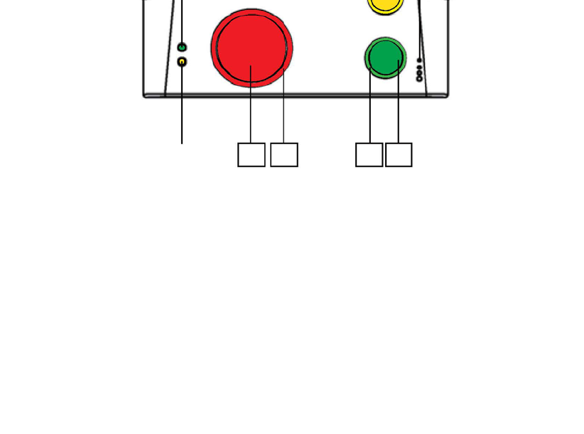
2.1. Identifying the Parts
Top View Back View
Side View

4
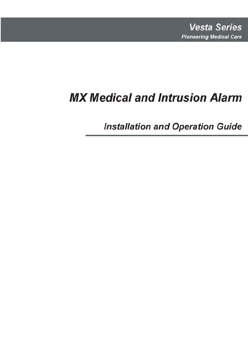
Control Panel Definitions
Button/LED/Component
Behavior Function/Indication
Pressed in idle/normal mode To summon emergency help
Pressed once in learning
mode
To select Pendant #2
1 Red Help Button
Pressed for 3 seconds in
learning mode
To delete a selected pendant
Dimly lit Idle/normal mode
Blinking 1. Guard time
2. Pauses during retries of
alarm reporting
2 Red Backlight
Brightly illuminating 1. Busy with alarm
reporting
2. After an alarm report
receives a callback and
until the call is hung up
Pressed in idle/normal mode 1. To reset the inactivity
timer
2. For the Control Panel to
report all the fault
problems it is
experiencing via voice
prompts
Pressed once before the
Control Panel dials out for
alarm reporting
To cancel the alarm reporting
Pressed once during or at
the end of a two-way
communication
To terminate the two-way
communication
Pressed for 3 seconds in
idle/normal mode
To make a non-emergency
call
3 Green Reset Button
Pressed once in learning
mode
To select Pendant #1
On 1. After a non-emergency
call is dialed out and until
the call ends
2. Busy with status
reporting
3. When two-way
communication is
opened after an
incoming call is picked
up and until the call ends
4 Green Backlight
Off 1. Idle mode
2. Pauses during retries of
status reporting

5
Button/LED/Component
Behavior Function/Indication
4 Green Backlight
Blinking (on MX-2 and MX-6
only)
The Control Panel has a
phone line fault.
Pressed once when serving
as an inactivity, check-in/out
or away/home button
To toggle on/off the inactivity
timer
Pressed once when serving
as a security button
To arm the system
Pressed once when serving
as a non-emergency button
To make a non-emergency
call
Pressed for 3 seconds To enter learning mode
5 Yellow Button can
serve as:
- Inactivity Button
- Check-in/out Button
- Away/Home Button
- Non-Emergency Call
Button
- Security Button
Pressed once in learning
mode
To exit learning mode
Steady on The inactivity timer is on.
Off The inactivity timer is off.
6 Orange Backlight
Blinking The Control Panel is in
learning mode.
Steady on AC power is on.
Blinking twice every second AC power fails.
7 Green LED (Volume
Switch)
Pressed once To increase the speaker
volume
Pressed once To lower the speaker volume
Blinking every 3 seconds The Control Panel is low on
battery or is having an
overvoltage condition.
Blinking twice every second A device is low on battery or
is tampered with.
8 Orange LED (Volume
Switch)
Off All the conditions signified by
this blinking orange LED
have been removed.
9 Microphone
10 Speaker
11 Battery Switch On/off
12 EZ-1/EZ-2 Lid
13 DC Jack Connects to a DC 12V 2A switching power adapter.
14 USB Port
15 Ethernet Port (On MX-6 and MX-8 only)
16 Phone Jack Marked
Connects to a phone line from the wall.
17 Phone Jack Marked Connects to a telephone unit.

6
Button/LED/Component
Behavior Function/Indication
On Failed registration
<
<N
NO
OT
TE
E>
>
) Registration will fail
when an AC power
failure occurs.
18 GPRS/GSM or 3G Fault
Indicator (orange)
Off Successful registration
19 GPRS/GSM or 3G
Status Indicator (red)
Blinking
When the GPRS/GSM or 3G
module operates normally
20 GPRS/GSM or 3G Reset
Button
Pressed for one second
To reset GPRS/GSM or 3G
21 SIM Card Base Insert your SIM card in this slot.
7
2.2. Power Supply
z Plug the AC power adapter into the Control Panel’s DC jack and connect
to the mains power. Make sure that you use an adapter with the
appropriate AC voltage rating to prevent component damage. An AC-DC
12V/2A switching power adapter is generally used to power the standard
version of the Control Panel.
z In addition to the AC power adapter, a rechargeable battery is installed
inside the Control Panel to serve as a backup in case of a power failure.
z During normal operation, the AC power adapter is used to supply power to
the Control Panel and at the same time recharge the battery. It takes
approximately 72 hours to fully charge the battery.
z If the battery switch is set as OFF, the battery will not be charged when
AC power is connected and nor will it serve as a backup power source
when AC power is missing. You need to switch the battery to ON for it to
be charged when AC power is connected and serve as a backup power
source when AC power is missing.

8
3. Installing MX
Step 1. Choose a suitable location for the Control Panel. The Control Panel
requires the mains power and PSTN (MX-2 and MX-6), GSM/3G
(MX-3 and MX-8) and/or Ethernet (MX-6 and MX-8) connections and
should be easily accessible. It should not be placed in a damp
location such as a bathroom or close to a heat source like a
microwave oven, which could reduce signal strength.
Step 2. Plug the USB cable into the Control Panel’s USB port and connect it to
a PC for MX programming.
Step 3. Connect a PSTN line and a telephone line to the Control Panel for MX
to operate via PSTN (MX-2 and MX-6 only).
Step 4. Insert a SIM card into the SIM card base on the rear side of the Control
Panel for MX to operate via GPRS and GSM or 3G (MX-3 and MX-8
only).
<
<N
NO
OT
TE
E>
>
) It is recommended that you disable the SIM card’s PIN code before you
insert the SIM card into the Control Panel.
) The SIM card will delete its messages whenever the Control Panel is
powered on.
Step 5. Plug an IP cable into the Control Panel’s Ethernet port and connect to
an Ethernet network for MX to operate via Ethernet (MX-6 and MX-8
only).
Step 6. Plug the AC power adaptor into the Control Panel’s DC jack and
connect to the mains power. The Control Panel will emit two beeps to
indicate the system is now ready for further operation.
9
4. Programming MX
4.1. PC Programming
4.1.1. Installing USB Driver
Please first install the USB Driver provided in your CD-ROM on your PC.
<
<N
NO
OT
TE
E>
>
) It is recommended that you use Windows XP or Windows 7 operating
systems.
Step 1. Plug the USB cable into the Control Panel’s USB port and connect it to
a PC.
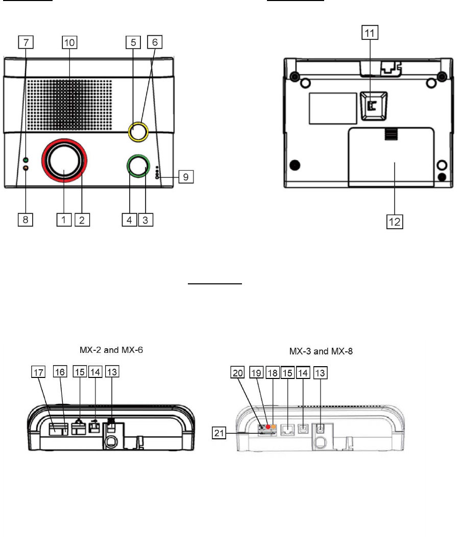
Step 2. Insert the supplied CD-ROM into your CD-ROM drive and find the
“USB Driver” folder (you may copy and paste the folder to your
desktop for later use). Click the “Start” button at the bottom left-hand
corner of the screen and then click “My Computer” and “Manage.”
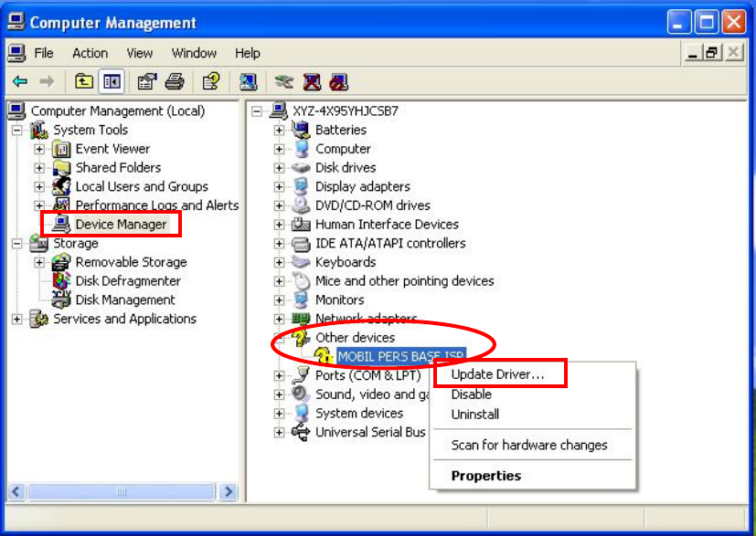
10
Step 3. Click on the “Device Manager” icon and find “MOBIL PERS BASE ISP”
under “Other devices.” Click “Update Driver.”
11
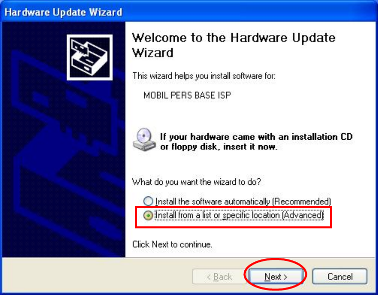
Step 4. When the Hardware Update Wizard window pops up, select “Install
from a list or specific location (Advanced)” and click “Next.”
12
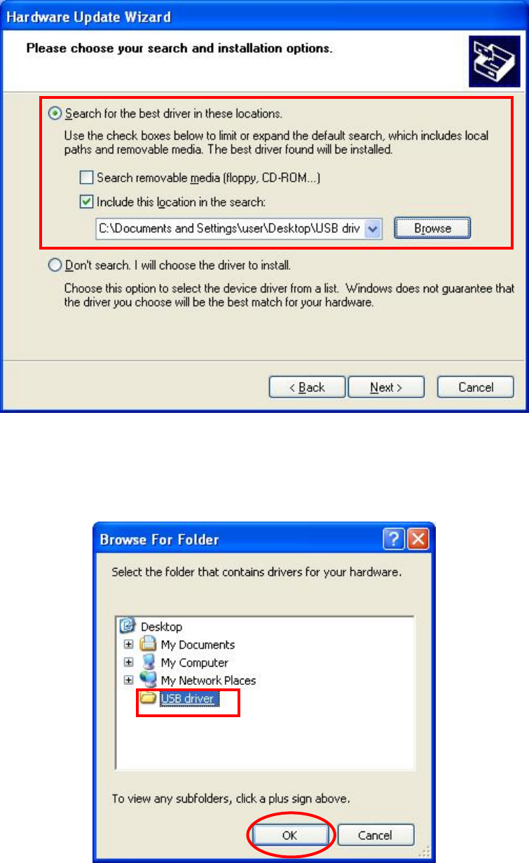
Step 5. Search for the USB Driver folder. If you have copied and pasted the
USB Driver folder to your desktop, tick “Include this location in this
search” and click “Browse.”
Step 6. Select the “USB Driver” and click “OK.”
13
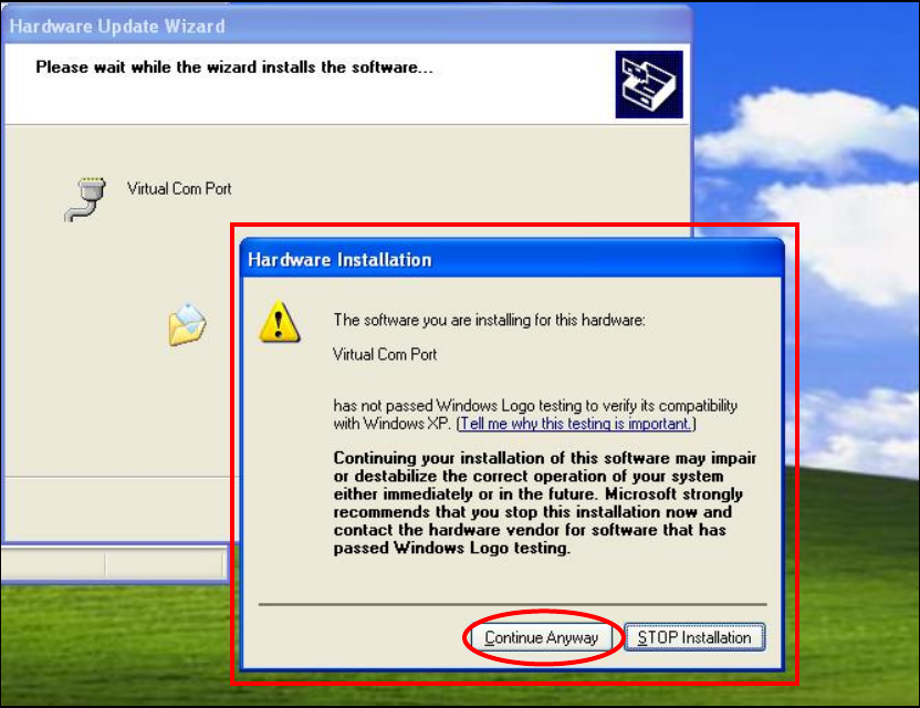
Step 7. It takes a short while for your PC to install the USB Driver. If the
Hardware Installation warning window pops up, please click
“Continue Anyway.”
14
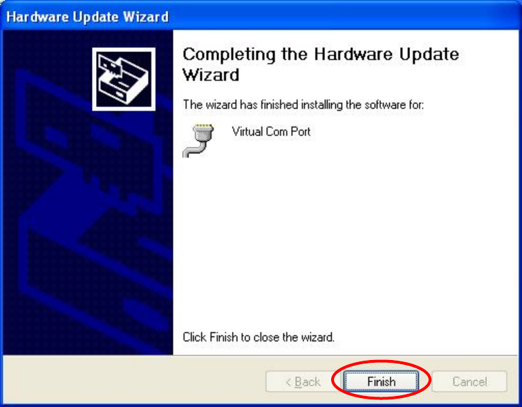
Step 8. When the installation has been completed, click “Finish” on the
Hardware Update Wizard window to close the wizard.
15
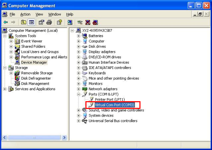
Step 9. Please remember the COM port number of MX as shown in the
“Device Manager” section. You will need the COM port number when
doing PC programming.
Now that the USB Driver has been successfully installed, you can
proceed with PC programming of MX.
16
4.1.2. PC Programming Tool
You can easily configure the Control Panel via the PC Programming Tool
provided in the CD-ROM.
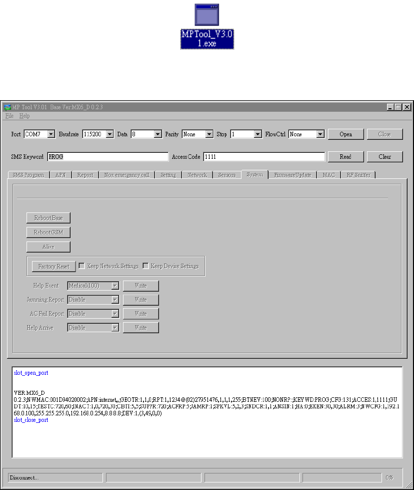
Step 1. Find and open the “PC Programming Tool” folder in the supplied
CD-ROM. Click “MPTool_x.xx.exe” to execute the programming tool.
The following configuration screen will be opened.
17
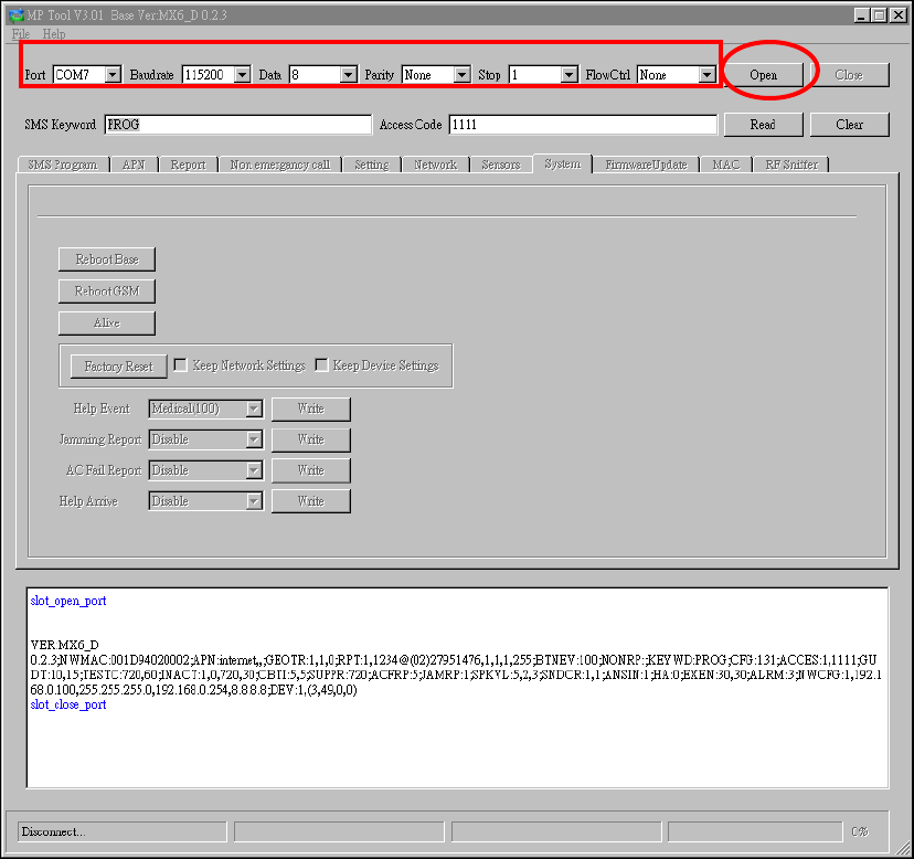
Step 2. Select the following settings in the top section of the configuration
screen and click “Open.”
z Port: Select the COM port generated for MX after installing the
USB Driver (the USB port connected to MX).
z Baud rate: 115200
z Data: 8
z Parity: None
z Stop: 1
z FlowCtrl: None
18
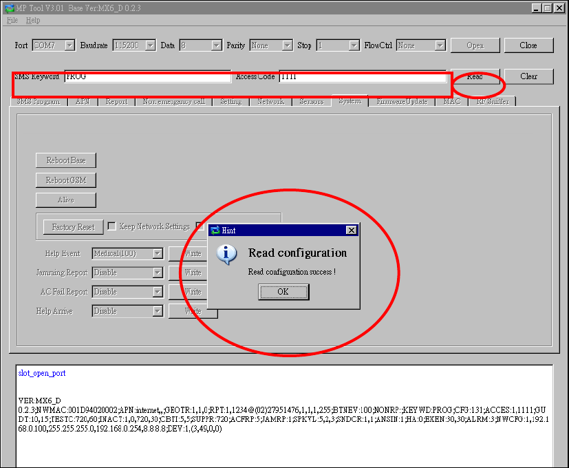
Step 3. Enter SMS Keyword and Access Code and click “Read.” When a
pop-up window shows “Read configuration success,” the
configuration page below will be opened and you can proceed with
the programming of MX.
z SMS Keyword: PROG (default)
z Access Code: 1111 (default)
19
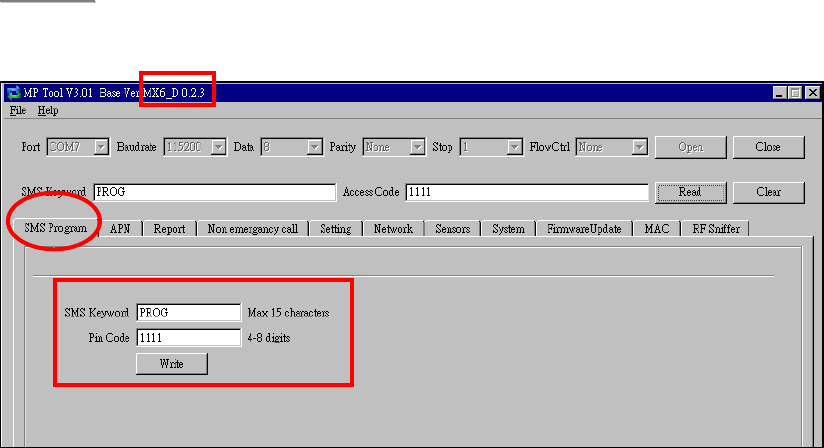
Step 4. SMS Program
Click “SMS Program” to set a SMS Keyword (15 characters max.) and a PIN
Code (4-8 digits) and click “Write.” Please note that the SMS Keyword is
case-sensitive.
<
<N
NO
OT
TE
E>
>
) The version of your MX model will be shown on the top of the screen.
20
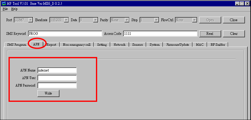
Step 5. APN
Click “APN” to set APN Name, APN User and APN Password and click “Write.”
z Access Point Name (APN): The name of an access point for GPRS.
Please ask your SIM card service provider for your APN.
z Username: Offered by your SIM card service provider. Please ask your
service provider for your GPRS username. If no username is required, you
may skip this step.
z Password: Offered by your SIM card service provider. Please ask your
service provider for your GPRS password. If no password is required, you
may skip this step.
21
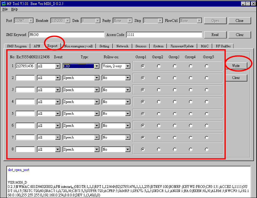
Step 6. Reporting
Click “Report” to program destinations of reporting, event filters (Event),
reporting formats (Type), follow-on options (Follow-on) and reporting sequence
(Group 1~5) for alarm reporting and status reporting. Click “Write” after you
have completed the settings.
z Destinations of reporting 1~8: Program destinations of reporting 1~8 in
the No. 1~No. 8 boxes.
z Event: Event filters have five options, “All,” “Medical,” “Emergency,”
“Status” and “Burglar.” Event filters are used to process events according
to the categories to which they belong. Please refer to “Appendix 7.1.9
Contact ID Event Codes” to check out the categories to which events are
assigned.
z Type: Select a reporting format for each destination of reporting. The
reporting formats include the following: Speech, CID, Scancom, Tunstall,
Franklin, CPC 1, CPC 2, CID_IP, SIA_CID_IP, SIA_IP, SIA_CID_UDP,
SIA_UDP, CSV_IP, SMS_CID, SMS_TEXT, and SMS_SIA.
z Follow-On: Select a follow-on option for each destination of reporting.
The follow-on options include the following: No, 2-way Voice
communication, Talk only, Listen-in only and Wait (for command). The
follow-on options should be in conformity with the settings of their
corresponding destinations of reporting.

22
z Group 1~Group 5: Groups 1~5 determine the sequence of reporting. The
reporting sequence goes from Group 1 to Group 5.
The procedure and details of programming are as follows:
1. Programming destinations of reporting: You can set 8 destinations of
reporting. To program destination 1, please first enter its reporting
number/setting in the No. 1 box and select its reporting format under “Type”
as well as its follow-on option under “Follow-On.” Configure destinations
2-8 in the same manner.
The setting of each destination of reporting shall be in conformity with the
destination’s reporting format under “Type.” Examples of reporting formats
are as follows:
- Reporting over IP (Ethernet or GPRS) in CID_IP/SIA_IP/SIA_CID_IP/
SIA_UDP/SIA_CID_UDP/CSV_IP formats: Account@server:port
example: 0001@59.124.123.66:50123
- Reporting over the phone in CID/Scancom/Tunstall/Franklin/CPC 1/
CPC 2 formats: Account@phone number
Example: 0001@(02)27940559
- Speech reporting over the phone: phone number
Example: 0912345678
- Reporting over the phone in SMS_CID/SMS_TEXT/SMS_SIA formats:
Account@phone number
Example: 0001@0912345678
<
<N
NO
OT
TE
E>
>
) The account number can contain 4 or 6 digits. The CMS may also
determine according to its capacity how many digits the account number
can contain.
) You can select the options in the “Follow-On” column (No/2-Way
Voice/Talk Only/Listen Only/Wait) for digital reporting formats, including
CID, Tunstall, Scancom, Franklin, CPC 1 and CPC 2 formats. Please note
that the “Follow-On” settings for all the other reporting formats have to be
“No.”
) If a destination of reporting contains digits in parentheses like
(02)27940559, the Control Panel will not dial the digits in the parentheses
when reporting via PSTN (it will only dial 27940559) but will dial the digits
in the parentheses when reporting via GSM (it will dial 0227940559).
) Jamming reports can be reported via all reporting formats under “Type”
except for the Scancom and Tunstall formats.
2. Programming event filters: Event filters have five options: “All,”
“Medical,” “Emergency,” “Status” and “Burglar.” Event filters are used to

23
process events according to the categories to which they belong. Please
refer to “Appendix 7.1.9. Contact ID Event Codes” to check out the
categories to which events are assigned.
Events are divided into four categories: medical, emergency, status and
burglary. If the option “all” is selected for a destination, all events will be
reported to this destination.
Examples are as follows:
- A device low on battery is a “status” event. If destinations 3 and 7 are set
as “status” and destination 5 as “all” in event filters, this status event will
be reported to destinations 3, 5 and 7.
- A fall sensor being inactive is a “medical” event. If destinations 1 and 6 are
set as “medical” and destination 5 as “all” in event filters, this medical
event will be reported to destinations 1, 5 and 6.
<
<N
NO
OT
TE
E>
>
) Events categorized as “status” do not have follow-on procedure
(2-way/listen in/talk only/wait). Events categorized as “medical,”
“emergency” or “burglary” will have follow-on procedure if you program
follow-on modes for them. The only exception is the home/away events
(the home event code is 3666 and the away event code 1666). These two
events belong to the “status” category but have follow-on procedure.
3. Assigning destinations 1~8 to Groups 1~5: Reporting sequence goes
from Group 1 Æ Group 2 Æ Group 3 Æ Group 4 Æ Group 5. Destinations of
reporting assigned to Group 1 will be reported to first, those assigned to
Group 2 reported to next, and the like.
If you want to assign destination 1 to Group 3, tick Group 3 for destination 1.
Assign destinations 2-8 to the groups in the same manner.
<
<N
NO
OT
TE
E>
>
) Each group can have more than one destination of reporting. If one group
has more than one destination of reporting, the reporting sequence will go
through all of this group’s destinations before moving on to the next
group’s destination(s).
) The reporting will go through a group’s destinations according to the
numerical sequence to which the destinations are assigned. For example,
when destinations 4 and 8 are assigned to Group 2, the reporting will go to
destination 4 first and then destination 8.
) One complete round of reporting for the system means reporting from
Group 1 Æ Group 2 Æ Group 3 Æ Group 4 Æ Group 5 and going through
all the groups’ destinations. The system will keep going through the
rounds of destinations until one reporting has been received successfully.
If the system has successfully reported to one destination in a group, the
system will consider that it has successfully reported to this group.
24
Therefore, the system will skip the rest of the destinations in this group
and go on reporting to the next group. For example, if destinations 2, 4
and 7 are assigned to Group 3 and the system has successfully reported
to destination 2, the system will skip destinations 4 and 7 and go on
reporting to Group 4.
After the system has completed one round of reporting (going from Group
1 Æ Group 2 Æ Group 3 Æ Group 4 Æ Group 5) and has successfully
reported to one group, it will consider that the event has been successfully
reported and will stop reporting. If the successful reporting takes place in
the midst of a round, the system will still report to the rest of the groups in
the round before stopping reporting. For example, if the successful
reporting takes place in Group 2, the system will no longer report to other
destinations in Group 2 but will still go on reporting to destinations in
Group 3, Group 4 and Group 5 before stopping reporting.
If the system has not successfully reported to any group, it will enter the
retry cycle to repeat another round of reporting.
) If no reporting is successfully received after the system has gone through
the first complete round, the system will take a 5-minute break before
starting the second round of reporting. If there is still no reporting
successfully received after the system has gone through the second
round, the system will again take a 5-minute break before starting the third
round of reporting. The system will never stop the reporting cycles unless
one reporting has been received successfully.
25
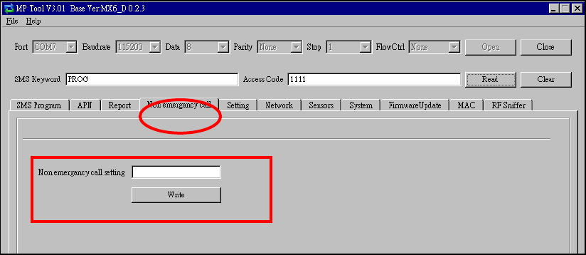
Step 7. Non-Emergency Call
z Click “Non-Emergency Call” to program the non-emergency call number
and click “Write.”
z When the Control Panel is in normal mode, you can make a
non-emergency call by pressing the green reset button for 3 seconds or
press the yellow button once (if the yellow button has been programmed
as a non-emergency call button). The Control Panel will emit 2 beeps and
automatically dial the programmed non-emergency call number for
two-way communication.
z During the conversation of a non-emergency call, you can enter the
following DTMF commands:
- Enter (1) to talk only.
- Enter (2) to open two-way voice communication.
- Enter (3) to listen in only.
- Enter (9) to hang up. You can also put the handset back to the base
cradle to end the call.
z During the conversation of a non-emergency call, you can extend the
communication by entering DTMF command (1), (2) or (3).
z At 20 and 10 seconds before the communication time expires, 1 beep will
be emitted via the telephone handset to alert the user. When the
communication time is up, the call will be automatically terminated.
z The communication time of non-emergency calls is conditioned by the
two-way timer function.
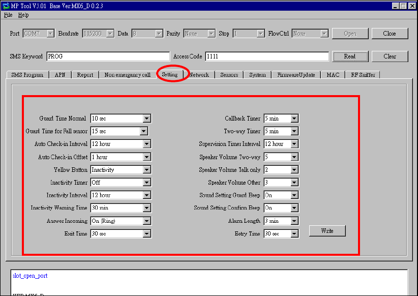
Step 8. Setting
26
Click “Setting” to program “Guard Time Normal,” “Guard Time for Fall Sensor,”
“Auto Check-In Interval,” “Auto Check-in Offset,” “Yellow Away/Home Button,”
“Inactivity Timer,” “Inactivity Interval,” “Inactivity Warning Time,” “Callback
Timer,” “Two-Way Timer,” “Supervision Timer Interval” and “Speaker Volume
Two-Way,” “Speaker Volume Talk Only,” “Speaker Volume Other,” Sound
Setting Guard Beep,” “Sound Setting Confirm Beep,” “Answer Incoming,”
“Alarm Length,” “Exit Time” and “Entry Time.”
Click “Write” when you have completed these settings.
Details regarding the settings are as follows:
1. Guard Time Normal:
z Guard time normal is designed for any compatible sensor except for Fall
Sensor (fall detection).
z A voice prompt announcing “help call in progress” will be played every 2-3
seconds during guard time to alert the user.
z If a false alarm is triggered, it can be canceled during guard time.
z An emergency alarm cannot be cancelled after guard time has expired.
z If an emergency alarm is triggered by Fall Sensor, guard time will be
determined by the setting of Fall Sensor instead of the setting of guard
time.
2. Guard Timer for Fall Sensor:
27
zYou can set a guard time period for Fall Sensor. A voice prompt
announcing “a fall has been detected” will be played every 2-3
seconds during Fall Sensor’s guard time.
zIf a false alarm is triggered by Fall Sensor, it can be canceled within the
guard time period.
zThis function is used when a fall is detected.
3. Auto Check-In Interval:
z You can select the length of the interval between auto check-in reports.
z There will be no auto check-in report if you select “Disable.”
z Whenever programming mode is accessed, the Control Panel will reset
the auto check-in timer.
4. Auto Check-In Offset:
z After power is supplied to the
Control Panel, the system will start counting the time for a check-in
report.
z The Control Panel will send a
check-in report once according to the setting of offset time. Afterwards
it will send reports according to the setting of auto check-in reports
unless the Control Panel restarts or the offset time is reset.
z When offset time is reset in
programming mode, the system will recalculate the time for a check-in
report.
z Whenever programming mode is
accessed, the Control Panel will reset the offset timer.
5. Yellow Button:
zYou can set the yellow button on the Control Panel as an inactivity button,
a check in/out button, an away/home button, a non-emergency call
button or a security button.
zAs an inactivity button: The user can use the inactivity button to toggle
on/off the inactivity timer. When the user presses the inactivity button
to toggle on/off the inactivity timer, the Control Panel does not report
event codes to the CMS.
zAs a check-in/out button: The user can use the check-in/out button to
toggle on/off the inactivity timer. When the user presses the
check-in/out button to check out and toggle off the inactivity timer, the
CID event code 665 with the prefix “1” will be sent to the CMS. When
the user presses the check-in/out button to check in and toggle on the
inactivity timer, the CID event code 665 with the prefix “3” will be sent
to the CMS.

28
zAs an away/home button: The user can use the away/home button to
toggle on/off the inactivity timer. When the user presses the
away/home button to toggle off the inactivity timer before leaving home,
the CID event code 666 with the prefix “1” will be reported to the CMS
and two-way communication will be opened after the reporting. When
the user presses the away/home button to toggle on the inactivity timer
upon returning home, the CID event code 666 with the prefix “3” will be
reported to the CMS and two-way communication will be opened after
the reporting.
zAs a non-emergency call button: The user can press this non-emergency
call button to dial a preset phone number.
zAs a security button: The user can press the security button to arm his
house and stop the inactivity timer (when the inactivity timer is set as
“on”). The user can select either of the following two methods to
disarm his house and restart the inactivity timer:
1. Press the security button once and press Wrist Pendant (WTR-)
once within three seconds after the security button is pressed.
2. Use Remote Control (RC) or Remote Keypad (KP) to disarm the
house and the inactivity timer will automatically restart.
<
<N
NO
OT
TE
E>
>
) If the inactivity timer is set as “on,” the timer will stop counting when the
user arms his house and goes out. The timer will start counting all over
again when the user returns home and disarms the house. The orange
backlight of the yellow button will be steady on no matter whether the
timer is stopped or continues running.
) If the inactivity timer is set as “off,” it will remain disabled no matter
whether the user arms or disarms his house. The orange backlight of the
yellow button will be turned off.
6. Inactivity Timer:
z If you set the inactivity timer as “on,” the orange backlight of the
yellow away/home button on the Control Panel will be steady on to
indicate that the inactivity timer is on. If you set the inactivity timer as
“off,” the orange backlight will be off.
z If the setting is “off,” no code will be sent to the CMS.
z When the Control Panel is in idle mode, you can toggle on/off the
inactivity timer by pressing the yellow button once (if the yellow button
has been programmed as an away/home button).
z If the yellow button has been programmed as a non-emergency call
button or a security button, you can only enable or disable the
inactivity timer via programming. However, when the yellow button is
programmed as a security button and the inactivity timer has been

29
enabled, the user can stop the inactivity timer when arming his house
and restart the inactivity timer when disarming his house.
<
<N
NO
OT
TE
E>
>
) Please set the inactivity timer as “off” if you program the yellow button as a
non-emergency call button or a security button.
7. Inactivity Interval:
zThis function monitors user movements and sends an inactivity report to
the CMS if the user fails to reset the inactivity timer before the interval
expires. This setting is for you to select the countdown period for the
inactivity timer.
zThe inactivity timer can be reset by pressing the reset button once on the
Control Panel or by an action from any device with a button.
zWhen the inactivity timer expires and no reset signal is received, the
Control Panel will start to play a voice prompt every five minutes to
alert the user during warning time. If a reset signal is still not received
after warning time expires, an inactivity alarm report will be made.
zThe reporting method for an inactivity alarm is the same as that for an
emergency alarm. The report will be sent based on your reporting
methods after the warning time expires.
8. Inactivity Warning Time:
z Inactivity warning time is the interval between the expiry of the
inactivity timer and the Control Panel’s sending an inactivity alarm
report to the CMS.
z The Control Panel will play a voice prompt upon the expiry of the
inactivity timer. Afterwards the voice prompt will be played every 5
minutes during warning time as a reminder to the user until the expiry
of warning time.
z If warning time is disabled, an inactivity alarm report will be
immediately sent to the CMS upon the expiry of the inactivity timer.
9. Callback Time:
z This setting is for digital reporting methods. After reporting
successfully to the CMS, the system will automatically hang up the
line and start a waiting period (=callback time) to auto answer any
incoming calls from the CMS.
z When the CMS calls back within callback time, the system will auto
answer the call after the first ring and wait for the entry of the proper
Access Code followed by the (#) key within 15 seconds.
z When the correct Access Code is received, the system will open
full-duplex communication to allow the call recipient to speak to the
30
CMS directly. You can use DTMF commands to switch
communication methods.
z The Access Code must be entered within 15 seconds, otherwise the
system will disconnect the call automatically.
z Press DTMF (9) or the reset button on the Control Panel to terminate
the call.
z When callback time is up, the system will automatically exit the
waiting mode and return to idle mode.
z The callback function is automatically disabled during an AC power
failure period.
10. Two-Way Timer:
z After the system makes a report to the CMS, it will immediately enter
a two-way communication period as programmed by this setting.
This will enable the user to speak directly with the CMS personnel.
z Pressing an assigned DTMF key can extend the two-way
communication by another two-way period.
11. Supervision Timer Interval:
z This function is not available for Scancom and speech reporting.
z When this supervisory function is enabled, the Control Panel will be
able to receive check-in signals from Wrist Pendants (WTR-),
Smoke Detector, Fall Sensor and Passive Infrared Motion Detector
that indicate the proper operation of the devices.
z When the supervision timer expires and no supervision signal is
received from WTR-, Smoke Detector, Fall Sensor or Passive
Infrared Motion Detector, a supervisory report will be made.
z The reporting method for a supervisory report is the same as that for
an emergency alarm. The report will be sent based on your reporting
method without guard time waiting.
12. Speaker Volume Two-Way:
z Select a preferred speaker volume level for two-way mode.
13. Speaker Volume Talk Only:
z Select a preferred speaker volume level for talk-only mode.
14. Speaker Volume Other:
z Select a preferred speaker volume level for other operations.
15. Sound Setting Guard Beep:
z Select “on” to enable beeps during guard time or “off” to disable the

31
beeping sound during guard time.
16. Sound Setting Confirm Beep:
z Select “on” to enable confirmation beeps during reporting or “off” to
disable confirmation beeps during reporting.
17. Answering Incoming [Calls]:
z When this function is set as “on,” the Control Panel rings for incoming
calls. You can answer an incoming call by pressing the red help
button on the Control Panel.
z When this function is set as “off,” the Control Panel remains silent
during incoming calls. Incoming calls will be directly hung up.
18. Alarm Length:
z Select the built-in siren duration when an alarm is activated.
19. Exit Time:
z Select the length of the exit time before your system enters armed
mode upon your departure from home.
20. Entry Time:
z Select the length of the entry time before the system changes from
armed mode to disarmed mode upon your arrival at home.
<
<N
NO
OT
TE
E>
>
) The settings of “Alarm Length,” “Exit Time” and “Entry Time” are functional
only when the yellow button on the Control Panel is programmed as a
security button.
32
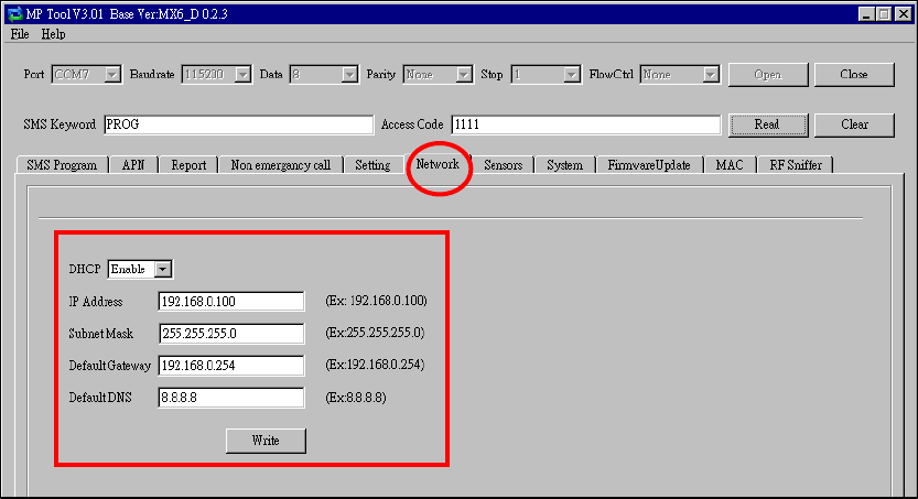
Step 9.
z Click “Network” to configure networking settings.
z Select “Enable” or “Disable” for the DHCP setting:
Enable: Select “Enable” if a DHCP server is present to enable settings to
be automatically assigned from the server. If you select “Enable,” you can
skip the “IP Address,” “Subnet Mask,” “Default Gateway” and “Default
DNS” settings. These settings will be automatically assigned. Click “Write”
directly after you have selected “Enable” for the DHCP setting.
Disable: Select “Disable” if a DHCP server is not available. If you select
“Disable,” you will have to configure the following “IP Address,” “Subnet
Mask,” “Default Gateway” and “Default DNS” settings. Click “Write” after
you have configured these settings.
33
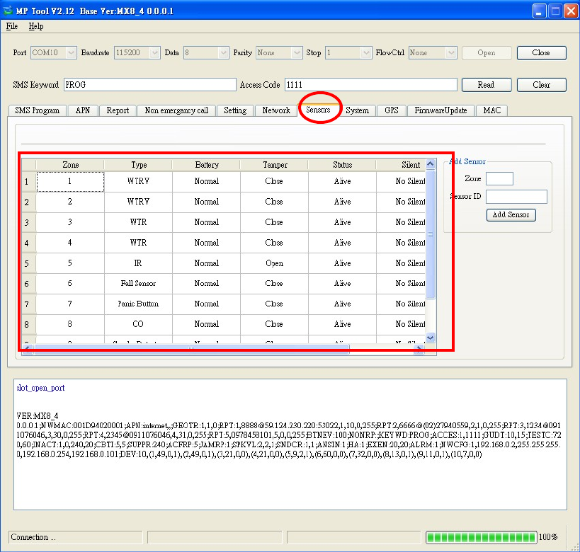
Step 10. Sensors
1. Viewing the data of sensors:
When you have learned sensors into the Control Panel via the local
learning method (see 5.1. Learning in Pendant #1, Pendant #2 and
Other Devices), you can click “Sensors” and “Read” to view the zone
numbers, types, battery status, tamper conditions, operating status and
sound attributes of all of the sensors that have been learned in.
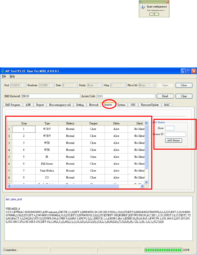
34
2. Adding sensors:
zIn addition to the local learning method, you can also use the “Add
Sensor” section on the “Sensors” page to learn sensors into the
Control Panel.
zEnter the zone number (Zone 1~Zone 100) to which you wish to assign a
sensor and the Sensor ID, which is the barcode on the back of the
sensor, and click “Add Sensor.” You can enter 1~100 in the zone
number box. A sensor ID is a combination of digits 1-9 and characters
A-F and can contain 10 or 14 characters (can be uppercase or
lowercase characters).
zIf the sensor is successfully added, this sign will pop up on
the screen. An “OK” will be shown at the bottom left-hand corner of the
screen and the newly added sensor will appear on the sensor list.
zIf you click “Add Sensor” and the word “Error” is shown at the bottom
left-hand corner of the screen, you may check whether the Sensor ID
is correct and whether the zone to which you assigned the sensor has
been occupied.
35
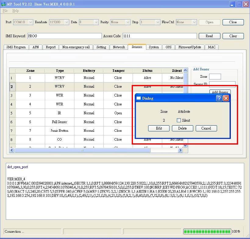
3. Editing and removing sensors:
z Editing the sound attribute of a sensor: Click any box in the section of the
sensor that you wish to configure. For example, if you wish to edit the
sound attribute of the sensor in Zone 3, you can click any box in the Zone
3 section. The “Dialog” pop-up window will be shown.
If you want the sensor in Zone 3 to be silent, tick “Silent” and “Edit.” If you
don’t want the sensor to be silent, leave the box in front of “Silent” blank
and tick “Edit.”
z Removing a sensor: If you want to remove the sensor in Zone 3, click
“Delete” on the popup window and the sensor will be removed. All devices
can be removed via PC programming.
z Click “Cancel” to close the “Dialog” popup window.
36
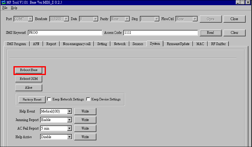
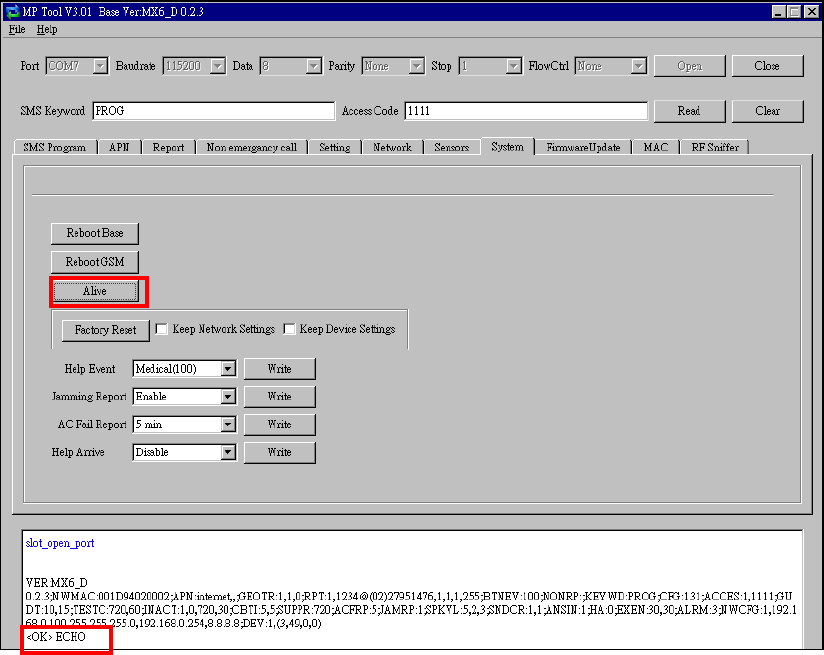
Step 11. System
When you click “System” to enter the “System” screen, you can carry out the
following operations:
1. Rebooting the Control Panel:
zYou can click “Reboot Base” to reboot the Control Panel. The Control
Panel will emit 2 beeps about 2 seconds after you click the “Reboot
Base” button. The following screen will be automatically closed and
you will need to restart the PC Programming Tool for further operation.
zRebooting the Control Panel will not affect the Control Panel’s
programmed parameters.
37
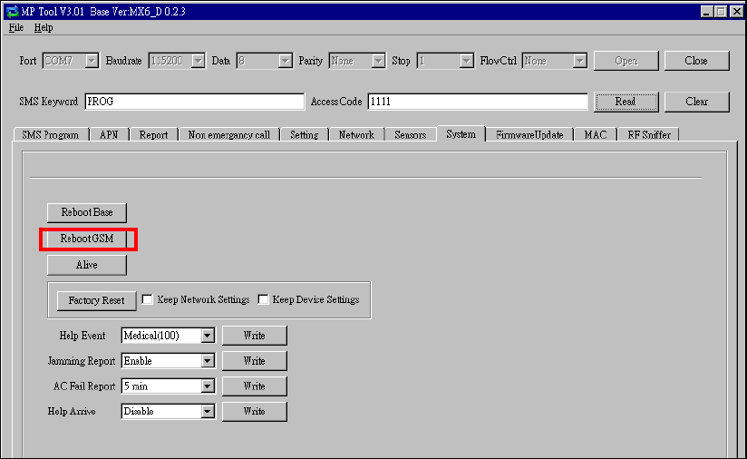
2. Rebooting GSM:
zIf this command is successful, the message “<OK> RSTG” will be shown
at the bottom left-hand corner of the screen.
38
3. Checking the condition of the Control Panel:
zYou can click “Alive” to check if the Control Panel can respond to your
commands properly.
zIf the Control Panel responds properly, the message “<OK> ECHO” will be
shown at the bottom left-hand corner of the screen.
39
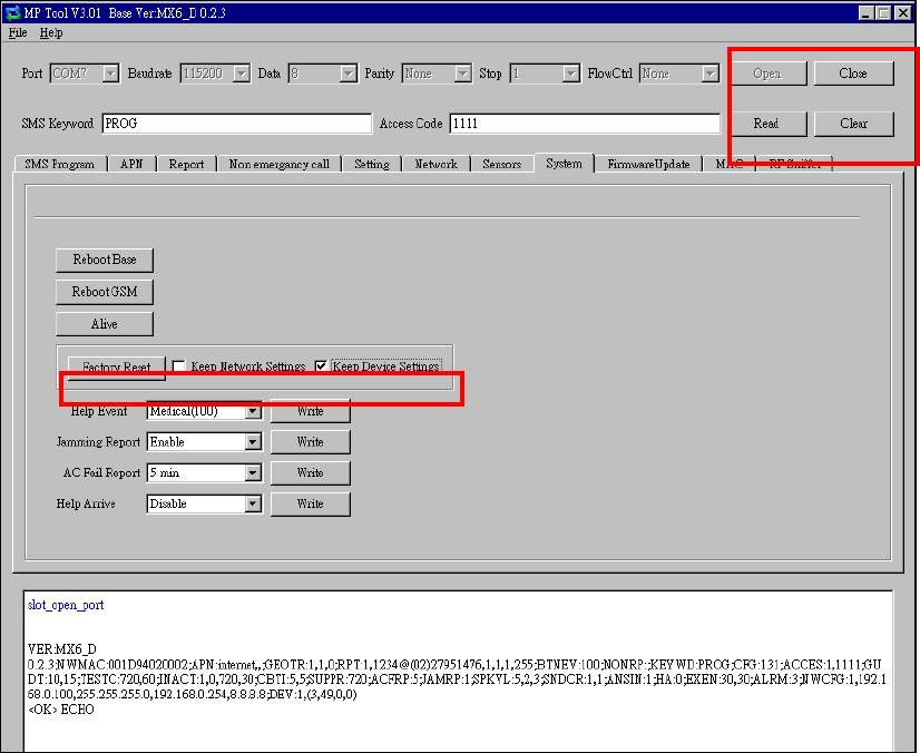
4. Restoring the system to factory settings:
zYou can click “Factory Reset” to restore the system to factory settings.
The system will immediately restore all programmed parameters to
factory settings and the Control Panel will emit 2 beeps after you click
the “Factory Reset” button.
zIf you want to keep your network settings and/or device settings, please
click the box(s) before these specifications before clicking “Factory
Reset.” Your network settings and/or device settings will then be
preserved while other programmed parameters are restored to factory
defaults.
zPlease do not close the configuration screen while the system is being
restored to factory defaults. It will take at least 3 minutes for the system
to complete this step.
zAfter the system has been restored to factory settings, you have two
options to proceed with further operation:
- You can close the PC Programming Tool and restart it, or
- You can click “Clear” and then “Read” to view the renewed settings.
40
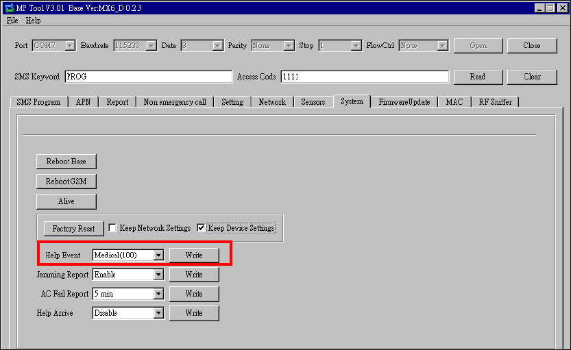
5. Selecting an event code:
zYou can select the event code to be sent to the CMS when the red button
of the Control Panel is pressed. Choose your preferred event code in
the box after “Help Event” and click “Write.”
zThere are four options for the event code:
- 100: Medical
- 101: Emergency
- 130: Burglary
- 120: Panic
41
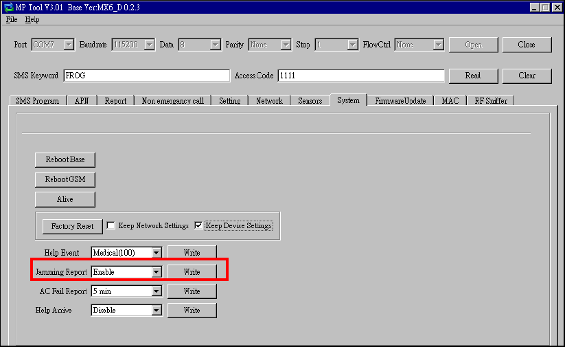
6. Jamming reports:
z You can select to enable or disable jamming reports. Select your
setting in the box after “Jamming Report” and click “Write.”
z Jamming reports can only be sent in the CID format and not in the
Scancom or Tunstall format.
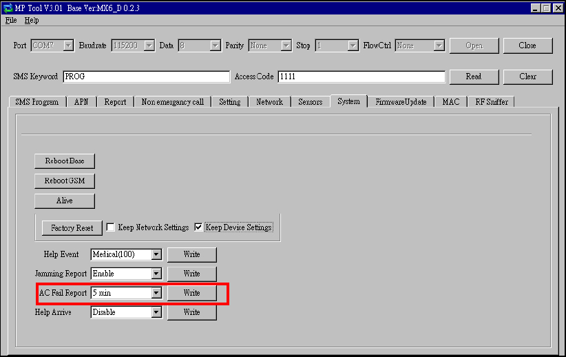
42
7. AC power failure reports:
z You can disable AC power failure reports or set the interval between
an AC power failure and the reporting of the power failure. Select your
setting in the box after “AC Fail Report” and click “Write.”
43
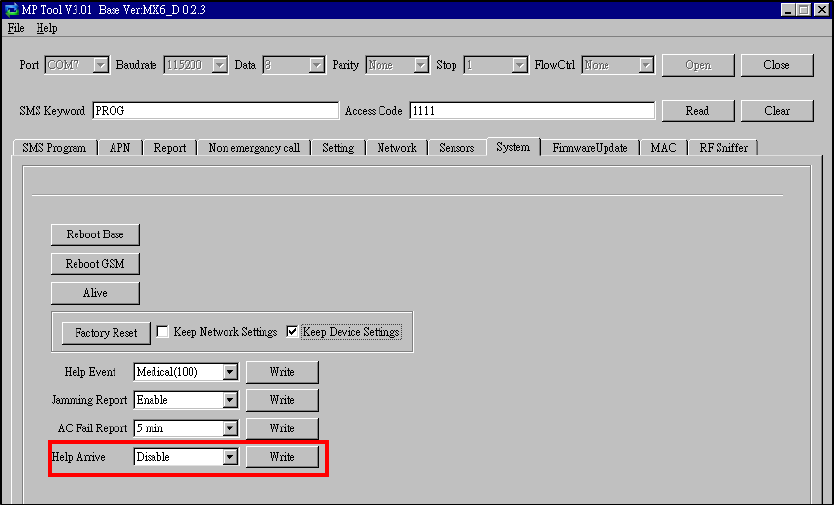
8. The help arrival function:
z You can select to enable or disable the help/nurse arrival function.
44
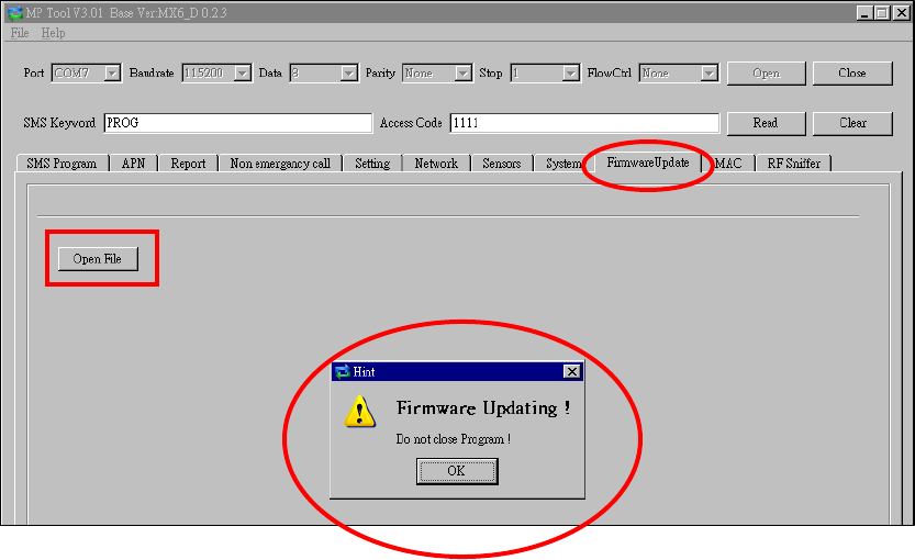
Step 12. Firmware Update
z You can update the firmware of MX by clicking on the “Firmware
Update” and the “Open File” buttons. Select the provided firmware
and a “Firmware Updating! Do not close program!” pop-up window
will appear. Click “OK” on the pop-up window for the updating process
to begin.
z The firmware update will take about 5 minutes to complete. Do not
close the PC programming tool while the updating process continues.
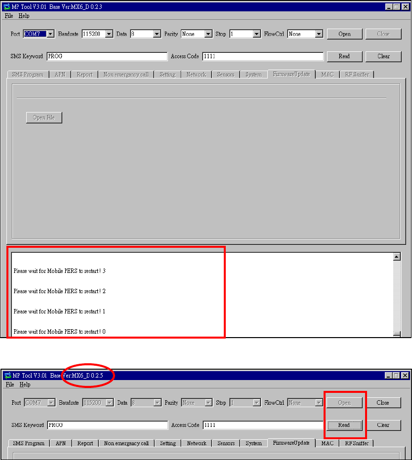
45
z When the firmware update is complete, a pop-up window will show
“Please wait for Panel restart.” Click “OK” on the pop-up window. The
countdown to the restart of the Control Panel will appear in the white
space at the bottom of the page. After the countdown, the Control
Panel will restart and emit 2 beeps. Do not close the PC programming
tool.
z After the restart of the Control Panel, click on the “Open” and the
“Read” buttons on the PC programming tool. The new firmware
version will be shown on the upper left-hand corner of the page.
46
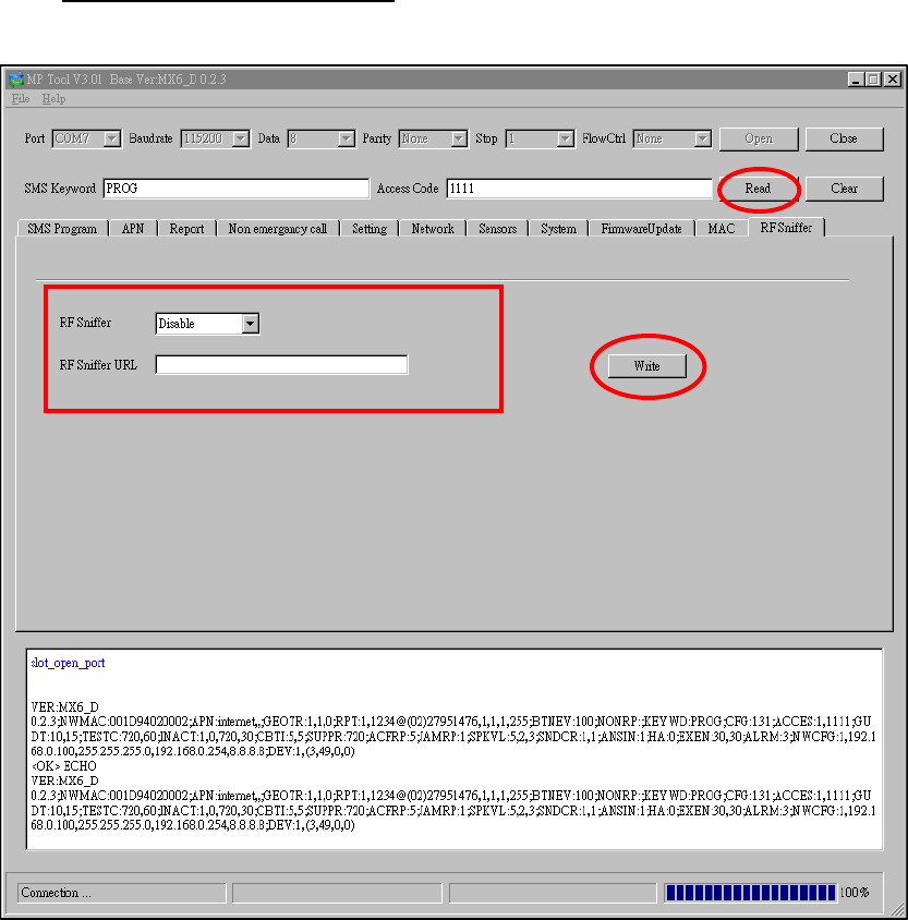
Step 13. RF Sniffer
z “RF Sniffer” is designed for the Control Panel to report to the monitoring
center when it receives a signal from a RF device that it has not learned. If
you select “Disable,” the Control Panel will not report to the monitoring
center when receiving such a signal. If you select “Enable,” the Control
Panel will report to the monitoring center when receiving such a signal.
z If you select “Enable,” please enter the “RF Sniffer URL” for the Control
Panel to report the signal and the ID of the RF device. Please program the
URL in the UDP format: Account@server:port (example:
0001@59.124.123.66:50123) Click “Write” after you complete the
settings.
47
4.2. Web Programming
4.2.1. Installing the Finder Software
<
<N
NO
OT
TE
E>
>
) This installation is required only of the first-time user.
) Web programming is applicable to MX-6 and MX-8 only.
) Before you begin web programming, please make sure that you have
plugged an IP cable into the Control Panel’s Ethernet port and connected
the cable to an Ethernet network for MX to operate via Ethernet.
Step 1. Insert the supplied CD-ROM into your CD-ROM drive.
Step 2. Find the “Finder” software in the CD-ROM.
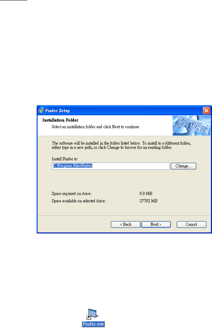
Step 3. Click on “Finder” to initiate the installation.
Step 4. Click on “Next” to rename the shortcut folder. If no renaming is
required, please click “Next” again to get ready for the installation.
Step 5. Click on “Next” again to begin the installation. Click on “Finish” when
the installation is completed.
Step 6. A new icon will be displayed on your desktop.
48
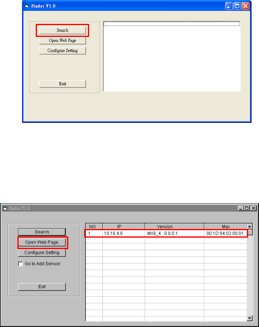
Step 7. Click “Finder.exe” to start the installation. The following screen will be
displayed:
Step 8. Click on “Search” for the software to start searching for a recognized
IP address within the local network service.
Step 9. You will be able to see your MX’s IP address on the list. The pop-up
window will display the product version and the MAC address of
your MX.
Step 10. After MX is identified, click on “Open Web Page” and enter the
username “admin” and password “admin1234” to be connected to the
configuration web page.
Step 11. The installation of the “Finder” software for MX is now completed.
49
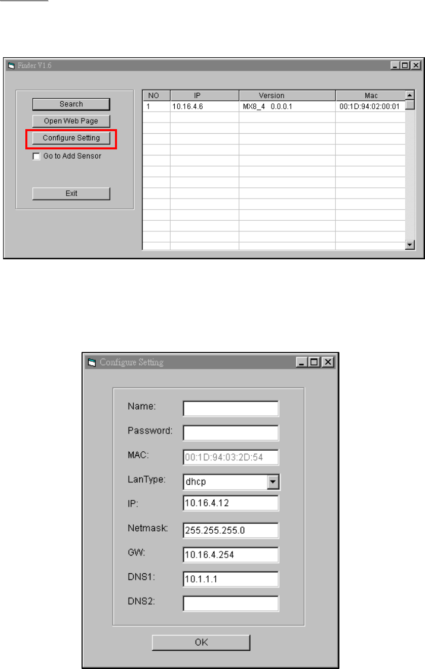
<
<N
NO
OT
TE
E>
>
) If you need to enter your internet data manually, click on the “Configure
Setting” button.
Enter your internet data, the MX username (default: admin) and password
(default: admin1234) and click on “OK” to confirm the settings. If the username
and password are correct, a pop-up window will display “Status: Configure
success!!”
50
4.2.2. Programming MX
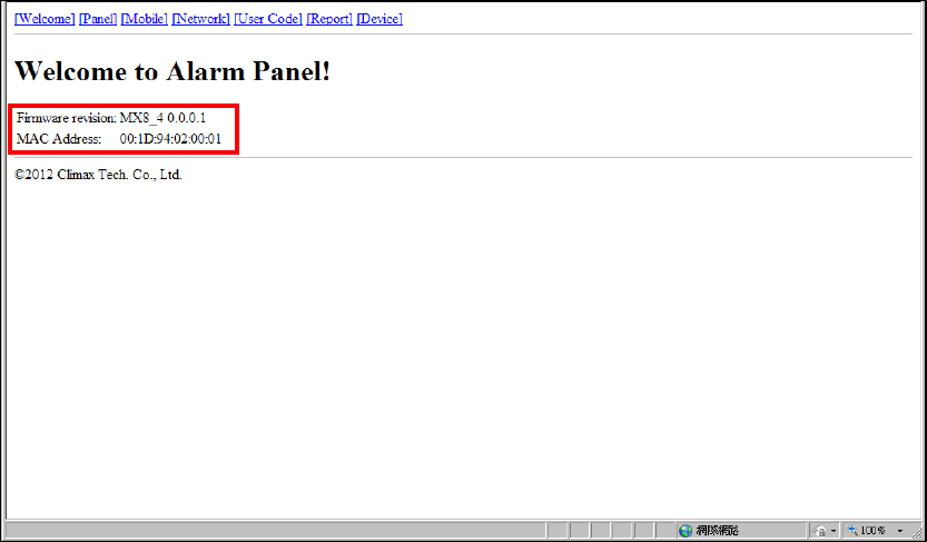
Step 1. Getting Connected to the Welcome Page
The welcome page to which your MX is connected will show the following
information:
z Firmware revision: The firmware version of the Control Panel
z MAC address: The MAC address of your MX
51
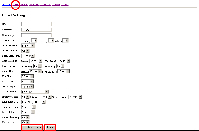
Step 2. Programming the Control Panel
Click on “Panel” at the top of the page to enter the “Panel Setting” page and to
configure the Control Panel’s settings. Click on “Submit Query” to save your
settings or click on “Reset” to return to default settings.
The details are as follows:
1. IDs: Please leave the boxes blank.
2. Keyword: Set a SMS keyword (15 characters max.). The default is PROG.
3. Non-emergency: Enter a non-emergency call number.
zWhen the Control Panel is in normal mode, you can make a
non-emergency call by pressing the green reset button for 3 seconds
or press the yellow button once (if the yellow button has been
programmed as a non-emergency call button). The Control Panel will
emit 2 beeps and automatically dial the programmed non-emergency
call number for two-way communication.
zDuring the conversation of a non-emergency call, you can enter the
following DTMF commands:
- Enter (1) to talk only.
- Enter (2) to open two-way voice communication.
- Enter (3) to listen in only.
- Enter (9) to hang up. You can also put the handset back to the base cradle
to end the call.
zDuring the conversation of a non-emergency call, you can extend the
communication by entering DTMF command (1), (2) or (3).
52
zAt 20 and 10 seconds before the communication time expires, 1 beep will
be emitted via the telephone handset to alert the user. When the
communication time is up, the call will be automatically terminated.
zThe communication time of non-emergency calls is conditioned by the
two-way timer function.
4. Speaker Volume:
z Two-way: Select a preferred speaker volume level for two-way mode.
z Talk only: Select a preferred speaker volume level for talk-only mode.
z Others: Select a preferred speaker volume level for other operations.
5. AC Fail Report: You can disable AC power failure reports or set the interval
between an AC power failure and the reporting of the power failure.
6. Jamming Report: You can select to enable (“On”) or disable (“Off”) jamming
reports. Jamming reports can be sent in the CID format but not in the
Scancom or Tunstall format.
7. Supervision Timer:
zThis function is not available for Scancom and speech reporting.
zWhen this supervisory function is enabled, the Control Panel will be able
to receive check-in signals from Wrist Pendants (WTR-), Smoke
Detector, Fall Sensor and Passive Infrared Motion Detector that
indicate the proper operation of the devices.
zWhen the supervision timer expires and no supervision signal is received
from WTR-, Smoke Detector, Fall Sensor or Passive Infrared Motion
Detector, a supervisory report will be made.
zThe reporting method for a supervisory report is the same as that for an
emergency alarm. The report will be sent based on your reporting
method without guard time waiting.
8. Auto Check-in:
zInterval:
- You can select the length of the interval between auto check-in
reports.
- There will be no auto check-in report if you select “Disable.”
- Whenever programming mode is accessed, the Control Panel will
reset the auto check-in timer.
zOffset Period:
- After power is supplied to the
Control Panel, the system will start counting the time for a check-in
report.
- The Control Panel will send a

53
check-in report once according to the setting of the offset period.
Afterwards it will send reports according to the setting of auto
check-in reports unless the Control Panel restarts or the offset
period is reset.
- When the offset period is reset in
programming mode, the system will recalculate the time for a
check-in report.
- Whenever programming mode is
accessed, the Control Panel will reset the offset timer.
9. Sound Setting:
z Guard Beep: Select “on” to enable beeps during guard time or “off” to
disable the beeping sound during guard time.
z Confirm Beep: Select “on” to enable confirmation beeps during
reporting or “off” to disable confirmation beeps during reporting.
10. Guard Time:
z Normal:
- Guard time normal is designed for any compatible sensor except
for Fall Sensor (fall detection).
- A voice prompt announcing “help call in progress” will be played
every 2-3 seconds during guard time to alert the user.
- If a false alarm is triggered, it can be canceled during guard time.
- An emergency alarm cannot be cancelled after guard time has
expired.
- If an emergency alarm is triggered by Fall Sensor, guard time will
be determined by the setting of Fall Sensor instead of the setting
of guard time.
z For Fall Sensor:
- You can set a guard time period for Fall Sensor. A voice prompt
announcing “a fall has been detected” will be played every 2-3
seconds during Fall Sensor’s guard time.
- If a false alarm is triggered by Fall Sensor, it can be canceled
within the guard time period.
- This function is used when a fall is detected.
11. Exit Time: Select the length of the exit time before your system enters
armed mode upon your departure from home.
12. Entry Time: Select the length of the entry time before the system changes
from armed mode to disarmed mode upon your arrival at home.
13. Alarm Length: Select the built-in siren duration when an alarm is activated.
<
<N
NO
OT
TE
E>
>
) The settings of “Exit Time,” “Entry Time” and “Alarm Length” are functional
only when the yellow button on the Control Panel is programmed as a

54
security button.
14. Yellow Button:
z You can set the yellow button on the Control Panel as an inactivity
button, a check in/out button, an away/home button, a
non-emergency call button or a security button.
z As an inactivity button: The user can use the inactivity button to
toggle on/off the inactivity timer. When the user presses the inactivity
button to toggle on/off the inactivity timer, the Control Panel does not
report event codes to the CMS.
z As a check-in/out button: The user can use the check-in/out button to
toggle on/off the inactivity timer. When the user presses the
check-in/out button to check out and toggle off the inactivity timer,
the CID event code 665 with the prefix “1” will be sent to the CMS.
When the user presses the check-in/out button to check in and
toggle on the inactivity timer, the CID event code 665 with the prefix
“3” will be sent to the CMS.
z As an away/home button: The user can use the away/home button to
toggle on/off the inactivity timer. When the user presses the
away/home button to toggle off the inactivity timer before leaving
home, the CID event code 666 with the prefix “1” will be reported to
the CMS and two-way communication will be opened after the
reporting. When the user presses the away/home button to toggle on
the inactivity timer upon returning home, the CID event code 666
with the prefix “3” will be reported to the CMS and two-way
communication will be opened after the reporting.
z As a non-emergency call button: The user can press this
non-emergency call button to dial a preset phone number.
z As a security button: The user can press the security button to arm
his house and stop the inactivity timer (when the inactivity timer is set
as “on”). The user can select either of the following two methods to
disarm his house and restart the inactivity timer:
1. Press the security button once and press Wrist Pendant (WTR-)
once within three seconds after the security button is pressed.
2. Use Remote Control (RC) or Remote Keypad (KP) to disarm the
house and the inactivity timer will automatically restart.
<
<N
NO
OT
TE
E>
>
) If the inactivity timer is set as “on,” the timer will stop counting when the
user arms his house and goes out. The timer will start counting all over
again when the user returns home and disarms the house. The orange
backlight of the yellow button will be steady on no matter whether the
timer is stopped or continues running.

55
) If the inactivity timer is set as “off,” it will remain disabled no matter
whether the user arms or disarms his house. The orange backlight of the
yellow button will be turned off.
15. Inactivity Timer:
z Inactivity Timer:
- If you set the inactivity timer as “On,” the orange backlight of the
yellow button on the Control Panel will be steady on to indicate
that the inactivity timer is on. If you set the inactivity timer as
“Off,” the orange backlight will be off.
- If the setting is “Off,” no code will be sent to the CMS.
- When the Control Panel is in idle mode, you can toggle on/off the
inactivity timer by pressing the yellow button once if the yellow
button has been programmed as an inactivity button, a
check-in/out button or an away/home button.
- If the yellow button has been programmed as a non-emergency
call button or a security button, you can only enable or disable
the inactivity timer via programming. However, when the yellow
button is programmed as a security button and the inactivity
timer has been enabled, the user can stop the inactivity timer
when arming his house and restart the inactivity timer when
disarming his house.
<
<N
NO
OT
TE
E>
>
) Please set the inactivity timer as “off” if you program the yellow button as a
non-emergency call button or a security button.
z Interval:
- This function monitors user movements and sends an inactivity
report to the CMS if the user fails to reset the inactivity timer
before the interval expires. This setting is for you to select the
countdown period for the inactivity timer.
- The inactivity timer can be reset by pressing the reset button
once on the Control Panel or by an action from any device with a
button.
- When the inactivity timer expires and no reset signal is received,
the Control Panel will start to play a voice prompt every five
minutes to alert the user during warning time. If a reset signal is
still not received after warning time expires, an inactivity alarm
report will be made.
- The reporting method for an inactivity alarm is the same as that
for an emergency alarm. The report will be sent based on your
reporting methods after the warning time expires.
z Warning Interval:
- The warning interval is the interval between the expiry of the
inactivity timer and the Control Panel’s sending an inactivity
alarm report to the CMS.
56
- The Control Panel will play a voice prompt upon the expiry of the
inactivity timer. Afterwards the voice prompt will be played every
5 minutes during the warning interval as a reminder to the user
until the expiry of warning time.
- If the warning interval is disabled, an inactivity alarm report will
be immediately sent to the CMS upon the expiry of the inactivity
timer.
16. Help Event Code:
z You can select the event code to be sent to the CMS when the red
button of the Control Panel is pressed.
z There are four options for the event code:
- Medical (100)
- Emergency (101)
- Burglary (130)
- Panic (120)
17. Two-way Timer:
z After the system makes a report to the CMS, it will immediately enter
a two-way communication period as programmed by this setting.
This will enable the user to speak directly with CMS personnel.
z Pressing an assigned DTMF key can extend the two-way
communication by another two-way period.
18. Callback Timer:
z This setting is for digital reporting methods. After reporting
successfully to the CMS, the system will automatically hang up the
line and start a waiting period (=callback time) to auto answer any
incoming calls from the CMS.
z When the CMS calls back within callback time, the system will auto
answer the call after the first ring and wait for the entry of the proper
Access Code followed by the (#) key within 15 seconds.
z When the correct Access Code is received, the system will open
full-duplex communication to allow the call recipient to speak to the
CMS directly. You can use DTMF commands to switch
communication methods.
z The Access Code must be entered within 15 seconds, otherwise the
system will disconnect the call automatically.
z Press DTMF (9) or the reset button on the Control Panel to terminate
the call.
z When callback time is up, the system will automatically exit the
waiting mode and return to idle mode.
z The callback function is automatically disabled during an AC power
57
failure period.
19. Answering Incoming [Calls]:
z When this function is set as “On,” the Control Panel rings for incoming
calls. You can answer an incoming call by pressing the red help
button on the Control Panel.
z When this function is set as “Off,” the Control Panel remains silent
during incoming calls. Incoming calls will be directly hung up.
20. Help Arrive: Select “On” to enable the help/nurse arrival function or “Off” to
disable the help/nurse arrival function.
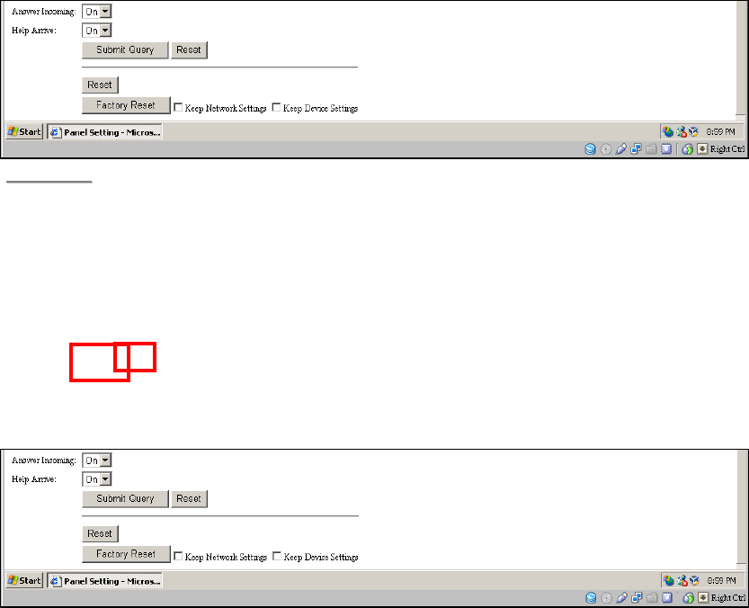
21. Reset:
z You can click on the “Reset” button at the bottom of the page (shown
in the picture below) to reboot the Control Panel. The Control Panel
will emit 2 beeps about 2 seconds after you click the “Reset” button.
z Rebooting the Control Panel will not affect the Control Panel’s
programmed parameters.
<
<N
NO
OT
TE
E>
>
) P
Pl
le
ea
as
se
e
c
cl
li
ic
ck
k
o
on
n
t
th
he
e
“
“R
Re
es
se
et
t”
”
b
bu
ut
tt
to
on
n
a
as
s
m
ma
ar
rk
ke
ed
d
b
be
el
lo
ow
w
t
to
o
r
re
eb
bo
oo
ot
t
t
th
he
e
C
Co
on
nt
tr
ro
ol
l
P
Pa
an
ne
el
l.
.
T
Th
he
e
“
“R
Re
es
se
et
t”
”
b
bu
ut
tt
to
on
n
n
ne
ex
xt
t
t
to
o
t
th
he
e
“
“S
Su
ub
bm
mi
it
t
Q
Qu
ue
er
ry
y”
”
b
bu
ut
tt
to
on
n
i
is
s
u
us
se
ed
d
t
to
o
r
re
es
st
to
or
re
e
s
se
et
tt
ti
in
ng
gs
s
o
on
n
t
th
hi
is
s
p
pa
ag
ge
e
t
to
o
d
de
ef
fa
au
ul
lt
t
v
va
al
lu
ue
es
s.
.
22. Factory Reset:
z You can click on “Factory Reset” to restore the system to factory settings.
The system will immediately restore all programmed parameters to factory
settings and the Control Panel will emit 2 beeps after you click the
“Factory Reset” button.
z If you want to keep your network settings and/or device settings, please
click the box(s) before these specifications before clicking “Factory
Reset.” Your network settings and/or device settings will then be
preserved while other programmed parameters are restored to factory
58
defaults.
<
<N
NO
OT
TE
E>
>
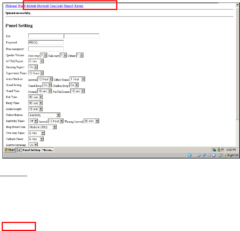
) After you click on “Submit Query” to save the settings, these words
“Updated successfully” will be shown at the top the page to confirm that
the Control Panel’s settings have been successfully updated.
59
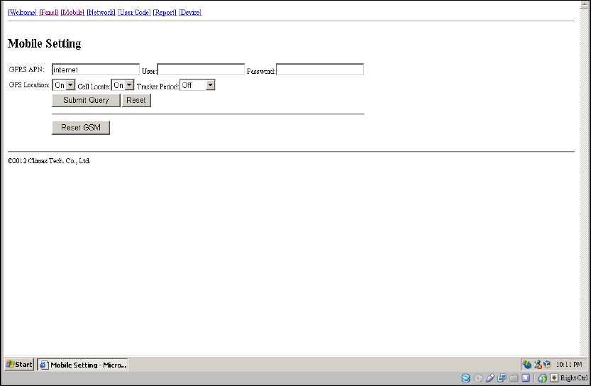
Step 3. APN
Click on “Mobile” at the top of the page. Configure GPRS settings and click on
“Submit Query” to save your settings. Click on “Reset” if you want to restore
the settings to default values.
The details are as follows:
1. GPRS settings:
zAccess Point Name (APN): The name of an access point for GPRS.
Please ask your SIM card service provider for your APN.
zUsername: Offered by your SIM card service provider. Please ask your
service provider for your GPRS username. If no username is required,
you may skip this step.
zPassword: Offered by your SIM card service provider. Please ask your
service provider for your GPRS password. If no password is required,
you may skip this step.
2. GPS Location: Please skip this setting.
3. Cell Locate: Please skip this setting.
4. Tracker Period: Please skip this setting.
60
5. Reset GSM: If this command is successful, the words “Updated
successfully” will be shown at the top of the page.
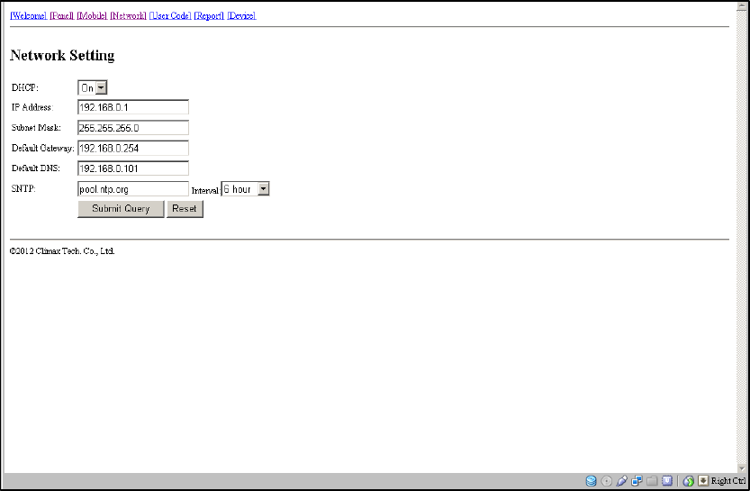
Step 4. Network Settings
z Select “On” or “Off” for the DHCP setting.
z DHCP “On”: Select “On” if a DHCP server is present to enable settings to
be automatically assigned from the server. If you select “On,” you can skip
the “IP Address,” “Subnet Mask,” “Default Gateway” and “Default DNS”
settings. These settings will be automatically assigned. Click “Submit
Query” directly after you have selected “On” for the DHCP setting.
z DHCP “Off”: Select “Off” if a DHCP server is not available. If you select
“Off,” you will have to configure the following “IP Address,” “Subnet Mask,”
“Default Gateway” and “Default DNS” settings. Click “Submit Query” after
you have configured these settings.
z SNTP and Interval: This link will automatically correct and update the
real-time system in your Control Panel and enable the Control Panel to
keep track of the current time. The updates will take place periodically
according to the “Interval” setting. It is recommended that you do not
change the website setting of SNTP unless you know a website that can
enable your Control Panel to keep track of your current local time.
61
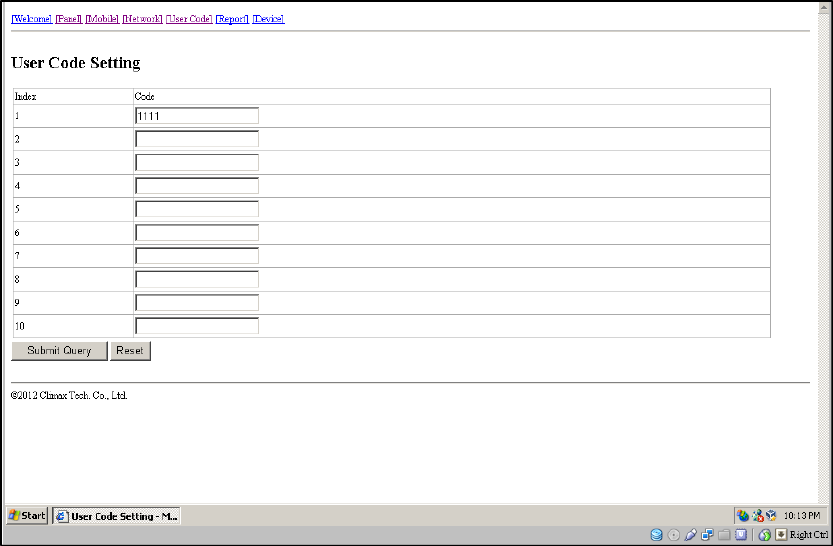
Step 5. User Code (Access Code)
Program user code(s) on this page and click on “Submit Query” to save your
setting(s). The default is 1111.
62
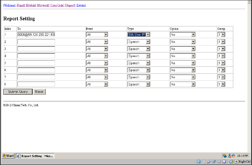
Step 6. Report Settings
Click “Report” to program destinations of reporting, event filters (Event),
reporting formats (Type), follow-on options (Option) and reporting sequence
(Group 1~5) for alarm reporting and status reporting. Click on “Submit Query”
after you have completed the settings.
z Destinations of reporting 1~8: Program destinations of reporting 1~8 in
the No. 1~No. 8 boxes.
z Event: Event filters have five options, “medical,” “emergency,” “status,”
“burglary” and “all.” Event filters are used to process events according to
the categories to which they belong. Please refer to “Appendix 7.1.9
Contact ID Event Codes” to check out the categories to which events are
assigned.
z Type: Select a reporting format for each destination of reporting. The
reporting formats include the following: speech, CID, Scancom, Tunstall,
Franklin, CPC 1, CPC 2, CID_IP, SIA_IP, SIA_CID_IP, SIA_UDP,
SIA_CID_UDP, CSV_IP, SMS_CID, SMS_TEXT, and SMS_SIA.
z Follow-On: Select a follow-on option for each destination of reporting.

63
The follow-on options include the following: No, 2-way voice
communication, talk only, listen-in only and wait (for command). The
follow-on options should be in conformity with the settings of their
corresponding destinations of reporting.
z Group 1~Group 5: Groups 1~5 determine the sequence of reporting. The
reporting sequence goes from Group 1 to Group 5.
The procedure and details of programming are as follows:
4. Programming destinations of reporting: You can set 8 destinations of
reporting. To program destination 1, please first enter its reporting
number/setting in the No. 1 box and select its reporting format under “Type”
as well as its follow-on option under “Follow-On.” Configure destinations
2-8 in the same manner.
The setting of each destination of reporting shall be in conformity with the
destination’s reporting format under “Type.” Examples of reporting formats
are as follows:
- Reporting over IP (Ethernet or GPRS) in CID_IP/SIA_IP/SIA_CID_IP/
SIA_UDP/SIA_CID_UDP/CSV_IP formats: Account@server:port
(example: 0001@59.124.123.66:50123)
- Reporting over the phone in CID/Scancom/Tunstall/Franklin/CPC 1/
CPC 2 formats: Account@phone number (example:
0001@0912345678)
- Speech reporting over the phone or reporting over the phone in
SMS_CID/SMS_TEXT/SMS_SIA formats: phone number (example:
0912345678)
<
<N
NO
OT
TE
E>
>
) The account number can contain 4 or 6 digits. The CMS may also
determine according to its capacity how many digits the account number
can contain.
) You can select the options in the “Follow-On” column (No/2-Way
Voice/Talk Only/Listen Only/Wait) for digital reporting formats, including
CID, Tunstall, Scancom, Franklin, CPC 1 and CPC 2 formats. Please note
that the “Follow-On” settings for all the other reporting formats have to be
“No.”
) If a destination of reporting contains digits in parentheses like
(02)27940559, the Control Panel will not dial the digits in the parentheses
when reporting via PSTN (it will only dial 27940559) but will dial the digits
in the parentheses when reporting via GSM (it will dial 0227940559).
) Jamming reports can be reported via all reporting formats under “Type”
except for the Scancom and Tunstall formats.
5. Programming event filters: Event filters have five options: “medical,”
“emergency,” “status,” “burglary” and “all.” Event filters are used to process

64
events according to the categories to which they belong. Please refer to
“Appendix 7.1.9. Contact ID Event Codes” to check out the categories to
which events are assigned.
Events are divided into four categories: medical, emergency, status and
burglary. If the option “all” is selected for a destination, all events will be
reported to this destination.
Examples are as follows:
- A device low on battery is a “status” event. If destinations 3 and 7 are set
as “status” and destination 5 as “all” in event filters, this status event will
be reported to destinations 3, 5 and 7.
- A fall sensor being inactive is a “medical” event. If destinations 1 and 6 are
set as “medical” and destination 5 as “all” in event filters, this medical
event will be reported to destinations 1, 5 and 6.
<
<N
NO
OT
TE
E>
>
) Events categorized as “status” do not have follow-on procedure
(2-way/listen in/talk only/wait). Events categorized as “medical,”
“emergency” or “burglary” will have follow-on procedure if you program
follow-on modes for them. The only exception is the home/away events
(the home event code is 3666 and the away event code 1666). These two
events belong to the “status” category but have follow-on procedure.
6. Assigning destinations 1~8 to Groups 1~5: Reporting sequence goes
from Group 1 Æ Group 2 Æ Group 3 Æ Group 4 Æ Group 5. Destinations of
reporting assigned to Group 1 will be reported to first, those assigned to
Group 2 reported to next, and the like.
If you want to assign destination 1 to Group 3, tick Group 3 for destination 1.
Assign destinations 2-8 to the groups in the same manner.
<
<N
NO
OT
TE
E>
>
) Each group can have more than one destination of reporting. If one group
has more than one destination of reporting, the reporting sequence will go
through all of this group’s destinations before moving on to the next
group’s destination(s).
) The reporting will go through a group’s destinations according to the
numerical sequence to which the destinations are assigned. For example,
when destinations 4 and 8 are assigned to Group 2, the reporting will go to
destination 4 first and then destination 8.
) One complete round of reporting for the system means reporting from
Group 1 Æ Group 2 Æ Group 3 Æ Group 4 Æ Group 5 and going through
all the groups’ destinations. The system will keep going through the
rounds of destinations until one reporting has been received successfully.
If the system has successfully reported to one destination in a group, the
system will consider that it has successfully reported to this group.
65
Therefore, the system will skip the rest of the destinations in this group
and go on reporting to the next group. For example, if destinations 2, 4
and 7 are assigned to Group 3 and the system has successfully reported
to destination 2, the system will skip destinations 4 and 7 and go on
reporting to Group 4.
After the system has completed one round of reporting (going from Group
1 Æ Group 2 Æ Group 3 Æ Group 4 Æ Group 5) and has successfully
reported to one group, it will consider that the event has been successfully
reported and will stop reporting. If the successful reporting takes place in
the midst of a round, the system will still report to the rest of the groups in
the round before stopping reporting. For example, if the successful
reporting takes place in Group 2, the system will no longer report to other
destinations in Group 2 but will still go on reporting to destinations in
Group 3, Group 4 and Group 5 before stopping reporting.
If the system has not successfully reported to any group, it will enter the
retry cycle to repeat another round of reporting.
) If no reporting is successfully received after the system has gone through
the first complete round, the system will take a 5-minute break before
starting the second round of reporting. If there is still no reporting
successfully received after the system has gone through the second
round, the system will again take a 5-minute break before starting the third
round of reporting. The system will never stop the reporting cycles unless
one reporting has been received successfully.
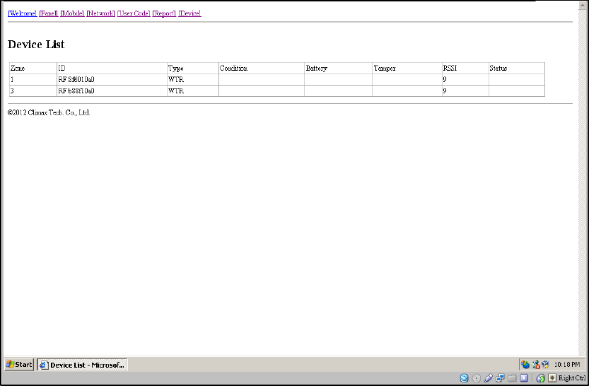
66
Step 7. Device List
The page of device list is only for you to view device status. You can learn in or
remove devices via local commands or use the PC Programming Tool to learn
in, remove or edit devices.
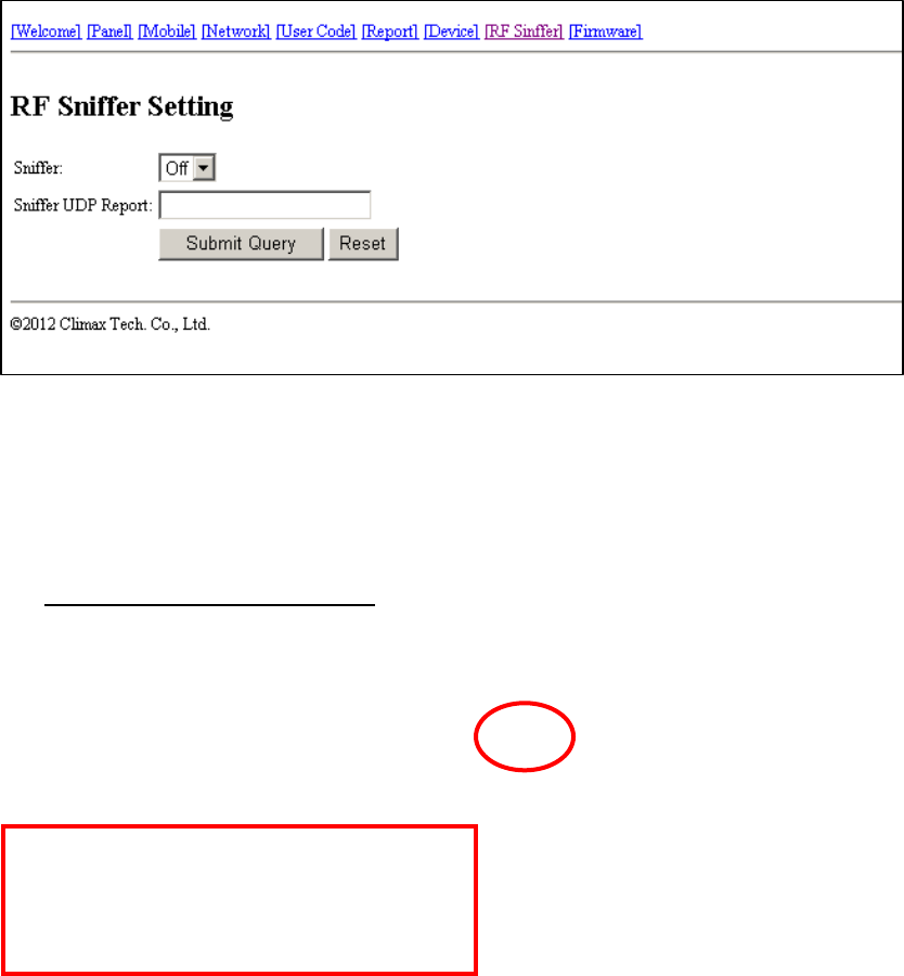
67
Step 8. RF Sniffer
z “RF Sniffer” is designed for the Control Panel to report to the monitoring
center when it receives a signal from a RF device that it has not learned. If
you select “Off,” the Control Panel will not report to the monitoring center
when receiving such a signal. If you select “On,” the Control Panel will
report to the monitoring center when receiving such a signal.
z If you select “On,” please enter the “RF Sniffer URL” for the Control Panel
to report the signal and the ID of the RF device. Please program the URL
in the UDP format: Account@server:port (example:
0001@59.124.123.66:50123) Click “Submit Query” after you complete the
settings.
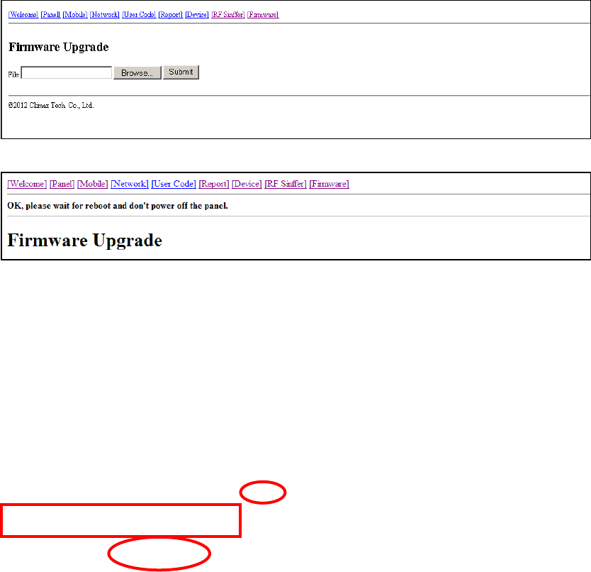
68
Step 9. Firmware Update
z You can update the firmware of MX by clicking on “Firmware” and
“Browse.” Select the provided firmware and click “Submit” for the updating
process to begin. The firmware update will take a few minutes.
z When the updating process is finished, the upper left-hand corner of the
page will show “OK, please wait for reboot and don’t power off the panel.”
The Control Panel will restart and emit 2 beeps. The firmware update is
complete.

69
4.3. SMS Programming
You can do SMS remote programming via a mobile phone or SMS iWizard.
SMS Remote Programming via a Mobile Phone
<
<N
NO
OT
TE
E>
>
) Please change the language setting of your mobile phone to English
before you proceed with SMS remote programming.
Step 1. Enter the SMS screen on your mobile phone or smartphone.
Step 2. Enter the programming command (see the SMS remote programming
commands tables below).
Step 3. Enter a colon (:).
Step 4. Enter SMS Keyword (default is PROG).
Step 5. Enter a comma (,).
Step 6. Enter the Access Code (default is 1111).
Step 7. Enter a comma (,).
Step 8. Enter the parameter(s).
Step 9. The composition of the command is completed. You can send the
command to the MX system now.
Example: To set 720 minutes for the supervision timer, you can send the
following command:
SUPPR:PROG,1111,720
SUPPR = Programming command
: = Colon
PROG = SMS Keyword

70
, = Comma
1111 = Access Code
, = Comma
720 = Programmed parameter
<
<N
NO
OT
TE
E>
>
) You can compose multiple commands in one SMS text message by using
“;” to separate each command.
SMS Remote Programming Commands Table
Item Command Example & Usage Default
GPRS APN,
username &
password
APN APN:PROG,1111,internet,,
To set GPRS APN, username and password (31 characters
max. for APN, 31 characters max. for username, 31
characters max. for password)
APN: Internet
Username and
password:
empty
Report settings RPT RPT:PROG,1111,1,0933111222,1,0,1,1
To configure report settings (index number, report
destination, group, type, follow-on option and event filter)
Index number: 1~8
Report destination: Depending on the reporting format
Group: 1~5
Type: 0 = Speech, 1 = CID, 2 = Scancom, 3 = Tunstall, 4 =
Franklin, 5 = CPC1, 6 = CPC2, 10 = CID_IP, 11 =
CID_SIA_IP, 12 = SIA_IP, 13 = SIA_CID_UDP, 14 =
SIA_UDP, 16 = CSV_IP, 30 = SMS_CID, 31 = SMS_TEXT,
33 = SMS_SIA
Follow-on option: 0 = No, 1 = Voice, 2 = Talk only, 3 = Listen
in only, 4 = Wait for command
Event filter: 255 = all, 1 = status, 2 = medical, 4 = emergency,
8 = burglary
No report
destination
Checking the
Control Panel
ECHO ECHO:PROG,1111
To check whether the Control Panel can respond properly
--
Rebooting the
Control Panel
RESET RESET:PROG,1111
To reboot the Control Panel
--
Keyword setting KEYWD KEYWD:PROG,1111,IPOG
To set the keyword
15 characters max. for the keyword
PROG
Non-emergency
call settings
NONRP NONRP:PROG,1111,0912345678
To program the non-emergency call number
15 digits max. for the phone number
--
Access Code ACCES ACCES:PROG,1111,1,1234 1111 for user 1

71
To set the Access Code (index number, code)
8 digits max. for the Access Code
Guard time
settings
GUDT GUDT:PROG,1111,10,15
To set the length of guard time periods (system: 0~180
seconds, fall sensor: 0~180 seconds)
10, 15
Auto check-in
reports
TESTC TESTC:PROG,1111,720,60
To configure the settings of auto check-in reports (interval:
0~21600 minutes, offset time: 0~1440 minutes)
720, 60
Item Command Example & Usage Default
Inactivity timer INACT INACT:PROG,1111,1,0,720,30
To configure settings of the inactivity timer (function type of
the yellow button, on or off, interval: 0~1440 minutes,
warning time: 0~60 minutes)
Button function type: 1 = away/home button, 2 =
non-emergency call button
On = 1, off = 0
1, 0, 720, 30
Callback time CBTI CBTI:PROG,1111,5,-1
To set callback time (duration: 0~1400 minutes, two-way
time: 1~60 minutes or -1 = no limits)
5, 5
Supervision SUPPR SUPPR:PROG,1111,720
To set the supervision timer (0~10080 minutes)
720
Speaker
volume levels
SPKVL SPKVL:PROG,1111,3,3,3
To set speaker volume levels (two-way: 1~5, talk only: 1~5,
others: 1~5)
2, 2, 3
Factory reset FTSET FTSET:PROG,1111,0,0
To execute a factory reset (to keep or not to keep NET
configurations, to keep or not to keep all devices and their
programmed attributes)
To keep NET configurations = 1; not to keep NET
configurations = 0
To keep all devices and their programmed attributes = 1; not
to keep all devices and their programmed attributes = 0
--
To set the CID
event code for
the red help
buttons
BTNEV BTNEV:PROG,1111,100
To set the CID event code sent when the Control Panel’s red
help button is pressed.
100 = medical event
101 = personal emergency
120 = panic report
130 = burglary
100
To enable/disable
voice prompts
during guard time
and confirmation
beeps
SNDCR
SNDCR:PROG,1111,1,1
To enable/disable voice prompts during guard time and
confirmation beeps
1 = enable
0 = disable
1, 1

72
RF jamming
reports
JAMRP JAMRP:PROG,1111,1
To enable/disable RF jamming reports
1 = enable
0 = disable
1
AC power
failure reports
ACFRP ACFRP:PROG,1111,5
To disable AC power failure reports or to set the interval
between an AC power failure and the reporting of the power
failure
0 = disable
1-60 = 1~60 minutes
5
Item Command Example & Usage Default
Answering
incoming calls
ANSIN ANSIN:PROG.1111.1
To allow or disallow incoming calls to be answered by pressing the
Control Panel’s red help button or a pendant button (1 = allow, 0 =
disallow)
1
Network
configuration
NWCFG NWCFG:PROG,1111,1,192.168.0.1,255.255.255.0,192.168.0.254,192.
168.0.101
To modify the local network configuration
DHCP: 0 = disabled (using static IP), 1 = enabled
IP, subnet mask, gateway, DNS address for static IP
1,192.168.0
.1,255.255.
255.0,192.1
68.0.254,19
2.168.0.101
73
SMS Remote Programming via SMS iWizard
MX is compatible with Climax’s SMS iWizard, which is designed to facilitate
SMS remote programming via a PC. This tool allows you to conveniently
program MX from your PC without sending SMS text messages from a mobile
phone.

74
5. Device Management
You can use the local learning method to learn 100 devices into the Control
Panel. Up to 4 DECT devices (DECT devices include WTRVS, CP-23 and
CTC-808RV) can be learned into the Control Panel. Devices that can be
learned into the Control Panel include the following:
z Door Contact: DC
z Remote Control: RC
z Remote Keypad: KP
z Water Sensor: WS
z Panic Button: PB
z Wrist Transmitter and Pendant Transmitter: WTR
z Passive Infrared Motion Detector: IR
z Smoke Detector: SD
z Gas Detector: GAS
z Carbon Monoxide Detector: CO
z Heat Detector: HD
z Glass Break Detector: GLS
z Fall Sensor: FALL
z Talking Pendant: WTRVS
z Call Point: CP-23
z Voice Satellite: CTC-808RV
<
<N
NO
OT
TE
E>
>
) Door Contact (DC): The device attribute of DC is set as “entry.” If DC is
triggered when the system is in armed mode, the Control Panel will start
an entry period to give the user enough time to disarm the system. If the
system is not successfully disarmed during the entry time, the Control
Panel will start an alarm upon the expiry of the entry time and report CID
code 130 to the CMS.
) Remote Control (RC): The device attribute of RC is set as “personal
attack.” When the panic button on RC is pressed for three seconds, the
Control Panel will report CID code 120 to the CMS.
) Remote Keypad (KP):

75
- The device attribute of KP is set as “personal attack” when the
dual-key function “1” + “3” is enabled. When the keys “1” and “3” are
pressed on KP at the same time, the Control Panel will report CID
code 120 to the CMS.
- The device attribute of KP is set as “fire” when the dual-key function “4”
+ “6” is enabled. When the keys “4” and “6” are pressed on KP at the
same time, the Control Panel will report CID code 110 to the CMS.
- The device attribute of KP is set as “medical” when the dual-key
function “7” + “9” is enabled. When the keys “7” and “9” are pressed on
KP at the same time, the Control Panel will report CID code 100 to the
CMS.
) Passive Infrared Motion Detector (IR): The device attribute of IR is set as
“entry.” If IR is triggered when the system is in armed mode, the Control
Panel will start an entry period to give the user enough time to disarm the
system. If the system is not successfully disarmed during the entry time,
the Control Panel will start an alarm upon the expiry of the entry time and
report CID code 130 to the CMS.
) Fall Sensor (FALL): The device attribute of Fall Sensor is “fall.” When a fall
is detected, the Control Panel will report CID event codes 120 and 102 to
the CMS.
5.1. Learning in Pendant #1, Pendant #2 and Other Devices
5.1.1. Learning in Pendant #1
For Wrist Transmitter (WTR- Series) and Fall Sensor
Step 1. When the Control Panel is in idle mode, press and hold the yellow
button for 3 seconds to enter learning mode.
Step 2. The Control Panel will emit 1 beep once the yellow button is pressed.
Release the yellow button when you hear 2 beeps, which indicate the
Control Panel is now in learning mode. The orange backlight begins
to blink.
Step 3. Press the green reset button once. The Control Panel will emit 1 beep.
Step 4. Press the button of Pendant #1 until the Control Panel emits 2 beeps
to indicate Pendant #1 has been learned into Zone 1.
Step 5. Press the yellow button on the Control Panel once to exit learning
mode.
<
<N
NO
OT
TE
E>
>
) If the Control Panel emits 3 beeps, that means a sensor has been
previously assigned to Zone 1.

76
For Talking Pendant (WTRVS) or Call Point (CP-23)
Step 1. When the Control Panel is in idle mode, press and hold the yellow
button for 3 seconds to enter learning mode.
Step 2. The Control Panel will emit 1 beep once the yellow button is pressed.
Release the yellow button when you hear 2 beeps, which indicate the
Control Panel is now in learning mode. The orange backlight begins
to blink.
Step 3. Press the green reset button once. The Control Panel will emit 1 beep.
Step 4. Press and hold the WTRVS/CP-23 button for 8 seconds until you hear
a long beep. The red LED of WTRVS/CP-23 is turned on.
WTRVS/CP-23 is now in learning mode. Now the LED of
WTRVS/CP-23 turns from red to green. The green LED blinks. The
Control Panel will emit two quick beeps. WTRVS/CP-23 will emit one
beep about 5 seconds later and its green LED will be turned on and
then go off instantly. WTRVS/CP-23 has been successfully learned in.
<
<N
NO
OT
TE
E>
>
) You cannot learn in the same WTRVS/CP-23 twice.
Step 5. Check if WTRVS/CP-23 has been learned in successfully. Press the
WTRVS/CP-23 button and you will hear continuous beeps from
WTRVS/CP-23.
Step 6. When WTRVS/CP-23 beeps, the Control Panel will respond with a
long beep to indicate that WTRVS/CP-23 is within the operation range.
Step 7. Press the yellow button on the Control Panel once to exit learning
mode.
<
<I
IM
MP
PO
OR
RT
TA
AN
NT
T
N
NO
OT
TE
E>
>
) Do not learn in the same device twice and do not learn in another
device when a device has been learned in previously. If you want to learn
in a device, please make sure that the previously learned device has been
removed first.
For Voice Satellite (CTC-808RV)
Step 1. When the Control Panel is in idle mode, press and hold the yellow
button for 3 seconds to enter learning mode.
Step 2. The Control Panel will emit 1 beep once the yellow button is pressed.
Release the yellow button when you hear 2 beeps, which indicate the
Control Panel is now in learning mode. The orange backlight begins
to blink.
Step 3. Press the green reset button once. The Control Panel will emit 1 beep.

77
Step 4. Press and hold CTC-808RV’s learning button for 5 seconds until you
hear 2 beeps. Release the button and CTC-808RV will emit one short
beep to indicate it is now in learning mode. The green LED of
CTC-808RV is turned on.
Step 5. When CTC-808RV is successfully learned in, both the Control Panel
and CTC-808RV will emit two beeps to indicate the successful
learning. The green LED on CTC-808RV will be turned off.
<
<N
NO
OT
TE
E>
>
) If you do not hear the two beeps and if CTC-808RV emits one short
beep and its green LED is off and red LED steady on, that means the
learning process has failed. Please repeat the learning steps again.
Step 6. Check if CTC-808RV has been learned in successfully. Press the
HELP button on CTC-808RV and you will hear continuous beeps
from CTC-808RV.
Step 7. When CTC-808RV beeps, the Control Panel will respond with one long
beep to indicate that CTC-808RV is within the operation range.
Step 8. Press the yellow button on the Control Panel once to exit learning
mode.
<
<I
IM
MP
PO
OR
RT
TA
AN
NT
T
N
NO
OT
TE
E>
>
) Do not learn in the same device twice and do not learn in another
device when a device has been learned in previously. If you want to learn
in a device, please make sure that the previously learned device has been
removed first.
5.1.2. Learning in Pendant #2
For Wrist Transmitter (WTR- Series) and Fall Sensor
Step 1. When the Control Panel is in idle mode, press and hold the yellow
button for 3 seconds to enter learning mode.
Step 2. The Control Panel will emit 1 beep once the yellow button is pressed.
Release the yellow button when you hear 2 beeps, which indicate the
Control Panel is now in learning mode. The orange backlight begins
to blink.
Step 3. Press the red help button once. The Control Panel will emit 1 beep.
Step 4. Press the button of Pendant #2 until the Control Panel emits 2 beeps
to indicate Pendant #2 has been learned into Zone 2.
Step 5. Press the yellow button on the Control Panel once to exit learning
mode.
<
<N
NO
OT
TE
E>
>

78
) If the Control Panel emits 3 beeps, that means a sensor has been
previously assigned to Zone 2.
For Talking Pendant (WTRVS) or Call Point (CP-23)
Step 1. When the Control Panel is in idle mode, press and hold the yellow
button for 3 seconds to enter learning mode.
Step 2. The Control Panel will emit 1 beep once the yellow button is pressed.
Release the yellow button when you hear 2 beeps, which indicate the
Control Panel is now in learning mode. The orange backlight begins
to blink.
Step 3. Press the red help button once. The Control Panel will emit 1 beep.
Step 4. Press and hold the WTRVS/CP-23 button for 8 seconds until you hear
a long beep. The red LED of WTRVS/CP-23 is turned on.
WTRVS/CP-23 is now in learning mode. Now the LED of
WTRVS/CP-23 turns from red to green. The green LED blinks. The
Control Panel will emit two quick beeps. WTRVS/CP-23 will emit one
beep about 5 seconds later and its green LED will be turned on and
then go off instantly. WTRVS/CP-23 has been successfully learned in.
<
<N
NO
OT
TE
E>
>
) You cannot learn in the same WTRVS/CP-23 twice.
Step 5. Check if WTRVS/CP-23 has been learned in successfully. Press the
WTRVS/CP-23 button and you will hear continuous beeps from
WTRVS/CP-23.
Step 6. When WTRVS/CP-23 beeps, the Control Panel will respond with a
long beep to indicate that WTRVS/CP-23 is within the operation range.
Step 7. Press the yellow button on the Control Panel once to exit learning
mode.
<
<I
IM
MP
PO
OR
RT
TA
AN
NT
T
N
NO
OT
TE
E>
>
) Do not learn in the same device twice and do not learn in another
device when a device has been learned in previously. If you want to learn
in a device, please make sure that the previously learned device has been
removed first.
For Voice Satellite (CTC-808RV)
Step 1. When the Control Panel is in idle mode, press and hold the yellow
button for 3 seconds to enter learning mode.
Step 2. The Control Panel will emit 1 beep once the yellow button is pressed.
Release the yellow button when you hear 2 beeps, which indicate the
Control Panel is now in learning mode. The orange backlight begins

79
to blink.
Step 3. Press the red help button once. The Control Panel will emit 1 beep.
Step 4. Press and hold CTC-808RV’s learning button for 5 seconds until you
hear 2 beeps. Release the button and CTC-808RV will emit one short
beep to indicate it is now in learning mode. The green LED of
CTC-808RV is turned on.
Step 5. When CTC-808RV is successfully learned in, both the Control Panel
and CTC-808RV will emit two beeps to indicate the successful
learning. The green LED on CTC-808RV will be turned off.
<
<N
NO
OT
TE
E>
>
) If you do not hear the two beeps and if CTC-808RV emits one short
beep and its green LED is off and red LED steady on, that means the
learning process has failed. Please repeat the learning steps again.
Step 6. Check if CTC-808RV has been learned in successfully. Press the
HELP button on CTC-808RV and you will hear continuous beeps
from CTC-808RV.
Step 7. When CTC-808RV beeps, the Control Panel will respond with one long
beep to indicate that CTC-808RV is within the operation range.
Step 8. Press the yellow button on the Control Panel once to exit learning
mode.
<
<I
IM
MP
PO
OR
RT
TA
AN
NT
T
N
NO
OT
TE
E>
>
) Do not learn in the same device twice and do not learn in another
device when a device has been learned in previously. If you want to learn
in a device, please make sure that the previously learned device has been
removed first.
5.1.3. Learning in Other Devices
Step 1. When the Control Panel is in idle mode, press and hold the yellow
button for 3 seconds to enter learning mode.
Step 2. The Control Panel will emit 1 beep once the yellow button is pressed.
Release the yellow button when you hear 2 beeps, which indicate the
Control Panel is now in learning mode. The orange backlight begins
to blink.
Step 3. Press the button of a device until the Control Panel emits 2 beeps to
indicate the device has been learned in. Please repeat this procedure
to learn in the rest of your devices. These devices will be
automatically assigned to Zone 3~Zone 100 by sequence.
<
<N
NO
OT
TE
E>
>

80
) The green reset button on the Control Panel assigns a pendant to Zone 1
and the red help button a pendant to Zone 2. If the green reset button or
the red help button is not pressed, devices will be automatically assigned
to Zone 3~Zone 100 by sequence.
Step 4. After you have learned in all the devices, press the yellow button once
to exit learning mode (1 beep will be emitted), or the Control Panel
will exit learning mode automatically after 5 minutes of inactivity. The
orange backlight will stop blinking upon the Control Panel exiting
learning mode.
<
<N
NO
OT
TE
E>
>
) Please refer to 6.1.5. Walk Test (Range Test) if you want to test the
operational ranges of your devices.
) You cannot learn in the same device twice. The Control Panel will emit 1
long beep to remind you that the device has been learned in previously.
5.2. Removing Pendant #1, Pendant #2 and Other Devices
All devices (those assigned to Zone 3~Zone 100) can be removed via PC
programming but only Pendant #1 and Pendant #2 can be removed by the
local removing method. Please refer to Step 10. Sensors of 4.1.2. PC
Programming Tool for details of how to delete devices via PC programming.
Removing Pendant #1 and Pendant #2 via the local removing method:
Step 1. When the Control Panel is in idle mode, press and hold the yellow
button for 3 seconds to enter learning mode.
Step 2. The Control Panel will emit 1 beep once the yellow button is pressed.
Release the yellow button when you hear 2 beeps that indicate the
Control Panel is now in learning mode. The orange backlight begins
to blink.
Step 3. Press the green reset button once to select Pendant #1. The Control
Panel will emit 1 beep when the green reset button is pressed.
Step 4. Press the red help button of the Control Panel for 3 seconds to delete
Pendant #1. The Control Panel will emit 1 beep once the red help
button is pressed. Release the red help button when you hear 2
beeps that indicate Pendant #1 has been removed.
Step 5. Press the red help button once to select Pendant #2. The Control
Panel will emit 1 beep when the red help button is pressed.
Step 6. Press the red help button of the Control Panel for 3 seconds to delete
Pendant #2. The Control Panel will emit 1 beep once the red help
button is pressed. Release the red help button when you hear 2
beeps that indicate Pendant #2 has been removed.

81
6. Operation
6.1. Control Panel
6.1.1. Idle Mode
When the Control Panel is in idle mode, it is ready to execute the following
functions.
6.1.1.1. Answering Incoming Calls
z The Control Panel emits cycles of 2 quick beeps for an incoming call.
z The user can answer the call by pressing the red help button on the
Control Panel.
z The user can also answer the call remotely by pressing the button on
WTRVS (Talking Pendant)/CP-23 (Call Point) or by pressing the
emergency button on CTC-808RV (Voice Satellite).
z Once the Control Panel has answered the call, it will open two-way voice
communication. You can use the volume switches on the Control Panel to
adjust the speaker volume level.
<
<N
NO
OT
TE
E>
>
) Press a DTMF key for over 1 second during the two-way communication
to enable a designed shortcut function.
- Enter (1) to talk only.
- Enter (2) to open two-way voice communication.
- Enter (3) to listen in only.
- Enter (9) to hang up. You can also put the handset back to the base
cradle to end the call.
- Press (6) or (4) to increase or decrease the speaker volume level in
two-way communication mode.
- Press any DTMF key except for the designed hang-up key (9) to add

82
another preset communication period. Communication periods are
conditioned by the two-way timer function.
- When a DTMF key is pressed, its designed shortcut function will be
executed and the communication time extended simultaneously.
If the speaker volume level is adjusted in two-way communication mode,
the adjusted value will be kept for the next usage.
) You can also press the green reset button on the Control Panel, the button
on WTRVS/CP-23 or the cancel button on CTC-808RV to hang up.
) Five minutes are allowed for each call (factory default is 5 minutes). The
calls are extensible.
) At 20 and 10 seconds before the communication time expires, 1 beep will
be emitted via the telephone handset to alert the user.
6.1.1.2. Non-Emergency Calls
Making a non-emergency call from the Control Panel
Step 1. Press the yellow button once or press the green reset button for 3
seconds when the Control Panel is in idle mode. One short beep will
be emitted and the Control Panel will dial the programmed
non-emergency call number.
<
<N
NO
OT
TE
E>
>
) The yellow button can be used as a non-emergency call button only after it
has been programmed as a non-emergency call button.
Step 2. If the call is successful, the Control Panel will open two-way
communication between the call recipient and the Control Panel. The
factory default of the communication time is 5 minutes. The
communication time is conditioned by the two-way timer function. The
green backlight illuminates during the conversation.
<
<N
NO
OT
TE
E>
>
) Press a DTMF key for over 1 second during the two-way communication
to enable a designed shortcut function.
- Enter (1) to talk only.
- Enter (2) to open two-way voice communication.
- Enter (3) to listen in only.
- Press any DTMF key except for the designed hang-up key (9) to add
another preset communication period. Communication periods are
conditioned by the two-way timer function.
- When a DTMF key is pressed, its designed shortcut function will be
executed and the communication time extended simultaneously.
) At 20 and 10 seconds before the communication time expires, 1 beep will

83
be emitted via the telephone handset to alert the user.
Step 3. Press DTMF (9) or the non-emergency call button to terminate the call.
The green backlight dims and the Control Panel returns to idle mode.
Making a non-emergency call from CTC-808RV
Step 1. Press the cancel button on CTC-808RV for 5 seconds. CTC-808RV
will emit a short beep.
Step 2. The Control Panel will dial the programmed non-emergency number.
The dialing tone can be heard on CTC-808RV.
Step 3. When the call is put through, CTC-808RV will open two-way voice
communication for the duration set by the Control Panel. The green
LED on CTC-808RV will turn steady on during the communication.
<
<N
NO
OT
TE
E>
>
) Press a DTMF key for over 1 second during the two-way communication
to enable a designed shortcut function.
- Enter (1) to talk only.
- Enter (2) to open two-way voice communication.
- Enter (3) to listen in only.
- Press any DTMF key except for the designed hang-up key (9) to add
another preset communication period. Communication periods are
conditioned by the two-way timer function.
- When a DTMF key is pressed, its designed shortcut function will be
executed and the communication time extended simultaneously.
) At 20 and 10 seconds before the communication time expires, 1 beep will
be emitted via the telephone handset to alert the user.
Step 4. Press the cancel button on CTC-808RV, DTMF (9) or the
non-emergency call button on the Control Panel to terminate the call.
The green LED on CTC-808RV will be turned off when the
communication ends.
6.1.1.3. AC Power Checkup
z If an AC power failure is detected to have lasted for 10 seconds or longer,
the green LED starts to blink as a visual warning to the user. 3G modules
will then be powered off, so SMS remote programming will become
unavailable. 3G modules will be powered on only during times of reporting.
An AC power failure report will be sent to all reporting numbers except for
the phone numbers programmed for speech reporting.
z When AC power is restored, the green LED will be steady on again.
z If an AC power failure has lasted for 5 minutes, the Control Panel will send

84
an AC failure report to the CMS.
<
<N
NO
OT
TE
E>
>
) The interval between an AC power failure and the Control Panel’s sending
the AC failure report (factory default is 5 minutes) is programmed as
explained in Step 10. System of 4.2. PC Programming Tool.
z After AC power has been restored for more than 5 minutes, the Control
Panel will send an AC power restored report to the CMS.
6.1.1.4. Control Panel Low on Battery
z When a low battery condition has lasted 4-6 minutes, the Control Panel
will report to the CMS and the green LED blinks every 2 seconds. The
report will be sent to all reporting numbers except for the phone numbers
programmed for speech reporting.
z After the battery voltage is restored and has lasted 5 minutes, the Control
Panel will send a battery power restored report to the CMS and the green
LED will be steady on again.
6.1.1.5. Control Panel’s Battery Disconnected
z The Control Panel detects battery absence in the following situations:
- Battery switched off
- Battery not connected
- Battery failure
z When battery disconnection has lasted 30 minutes, the Control Panel will
report to the CMS and the green LED blinks slowly.
z After the battery is restored and the restoration has lasted 30 minutes, the
Control Panel will send a battery restored report to the CMS and the green
LED will be steady on again.
6.1.1.6. Devices Low on Battery
z When a device is low on battery, the Control Panel’s green LED blinks
every 2 seconds (please refer to the figure on page 4 and the chart on
page 6).
z After the faulty battery is replaced, the Control Panel will instantly send a
battery restored report to the CMS regarding the particular device.
z If multiple sensors are running low on battery, the green LED won’t stop
blinking until all the sensors’ low battery status has been cleared.

85
6.1.1.7. Automatic Check-In Reports
z When the Control Panel is programmed to send auto check-in reports, it
will dispatch the reports to the CMS accordingly.
z After the Control Panel is powered on, the first auto check-in report it
sends will be conditioned by the setting of the offset timer. Afterwards auto
check-in reports will be sent according to the setting of the auto check-in
timer.
z The auto check-in timer will be reset whenever programmed mode is
entered.
<
<N
NO
OT
TE
E>
>
) If the setting of the offset timer or the auto check-in timer is changed, the
next auto check-in report will be sent according to the setting of the offset
timer. Afterwards auto check-in reports will be sent according to the setting
of the auto check-in timer.
6.1.1.8. Inactivity Timer
z When the inactivity timer is enabled (the orange backlight of the yellow
button will be on), its countdown period starts immediately after the
Control Panel is powered on or when the Control Panel exits programming
mode.
z When the inactivity timer is not reset, the Control Panel will send an
inactivity timer expired report to the CMS after warning time expires.
z The inactivity timer can be reset by pressing the reset button once on the
Control Panel, by an action from any device with a button or by an action
from Passive Infrared Motion Detector.
z You can disable the inactivity timer by programming it as “off.” The orange
backlight will be off.
z When the inactivity timer is enabled and toggled on by pressing the yellow
button, the orange backlight will be on. When the inactivity timer is
enabled and toggled off by pressing the yellow button, the orange
backlight will be off.
z When the yellow button is programmed as a security button, the user can
press the security button to arm his house and stop the inactivity timer
(when the inactivity timer is set as “on”). The user can select either of the
following two methods to disarm his house and restart the inactivity timer:
1. Press the security button once and press Wrist Pendant (WTR-) once
within three seconds after the security button is pressed.
2. Use Remote Control (RC) or Remote Keypad (KP) to disarm the house

86
and the inactivity timer will automatically restart.
<
<N
NO
OT
TE
E>
>
) If the inactivity timer is set as “on,” the timer will stop counting when the
user arms his house and goes out. The timer will start counting all over
again when the user returns home and disarms the house. The orange
backlight of the yellow button will be steady on no matter whether the
timer is stopped or continues running.
) If the inactivity timer is set as “off,” it will remain disabled no matter
whether the user arms or disarms his house. The orange backlight of the
yellow button will be turned off.
z When the yellow button is programmed as a non-emergency call button,
the inactivity timer can still be running. In this case you will have to disable
or enable the inactivity timer via programming, for you cannot toggle on/off
the inactivity timer by pressing the yellow button.
<
<N
NO
OT
TE
E>
>
) If no movement is detected during the preset inactivity time, the Control
Panel will send CID event code 641 with a fixed zone number regardless
of the zones the triggered motion detectors occupy.

87
z The user can turn on/off the inactivity timer when the yellow button is
programmed as an inactivity button, a check-in/out button or an
away/home button. If the inactivity timer is set as “on” and the yellow
button is programmed as a security button, the user can stop the inactivity
timer when arming his house and restart the inactivity timer when
disarming his house. Comparison of the Control Panel’s behavior in these
three different settings is shown in the chart below:
Button type The event
code reported
when the
yellow button is
pressed
Behavior of the
orange
backlight of the
yellow button
Confirmation
beeps
The backlight
that shows the
Control Panel
is reporting
Inactivity
button
None On: Inactivity
timer on
Off: Inactivity
timer off
None None
Check-in/out
button
Check-in: 3665
Check-out:
1665
Check-in: On
(Inactivity timer
on)
Check-out: Off
(Inactivity timer
off)
None (status
reporting)
The orange
backlight of the
yellow button is
on when the
Control Panel
is reporting.
The orange
backlight goes
off when the
reporting ends.
Away/home
button
Away: 1666
Home: 3666
Away: Off
(Inactivity timer
off)
Beeps during
alarm reporting
The red
backlight of the
red button is on
when the

88
Home: On
(Inactivity timer
on)
Control Panel
is reporting.
The red
backlight goes
off when the
reporting ends.
Security button None On: Inactivity
timer on
Off: Inactivity
timer off
Please refer to
section 6.2.3. None
6.1.2. Alarm Activation
Alarm triggered by the Control Panel, WTRVS/CP-23 or CTC-808RV
Alarm triggered by the Control Panel
z When an alarm is triggered, the Control Panel will enter guard time. Both
the orange backlight and the red backlight will turn steady on. A voice
prompt announcing “help call in progress” will be played every 2-3
seconds during guard time to alert the user.
z You can cancel the alarm reporting by pressing the reset button on the
Control Panel during guard time. The Control Panel will return to idle
mode.
z You cannot cancel the alarm reporting by pressing the reset button on the
Control Panel after guard time has expired.
z After guard time expires, the Control Panel will summon help based on the
programmed reporting methods. Beeps (about one beep per second) will
continue to be heard after the Control Panel dials out to inform you that
the call is in progress (no matter which reporting method is adopted).
z Confirmation beeps stop after 2-3 minutes.
<
<N
NO
OT
TE
E>
>
) When an alarm is triggered by any device other than WTRVS/CP-23 and
CTC-808RV, two-way communication will be established between the
CMS and the Control Panel. If an alarm is triggered by WTRVS/CP-23 or
CTC-808RV, two-way communication will be established between the
CMS, WTRVS/CP-23 and/or CTC-808RV.
) If an alarm is triggered by a DECT device (WTRVS/CP-23/CTC-808RV),
the Base Station’s DECT function will not be shut down when two-way
voice communication is conducted via PSTN or GSM/3G.
) If an alarm is triggered by the Base Station, the Base Station’s DECT
function will be shut down when two-way voice communication is

89
conducted via PSTN.
Alarm triggered by Talking Pendant (WTRVS) or Call Point (CP-23)
z Press the button on WTRVS/CP-23 to trigger an alarm. WTRVS/CP-23
will emit confirmation beeps until it receives a DTMF command. The
reception of a DTMF command indicates that the connection has been set
up successfully.
z If an alarm is triggered by WTRVS/CP-23, you can cancel the alarm by
pressing the WTRVS/CP-23 button for 8 seconds during guard time.
z When WTRVS/CP-23 is triggered, the Control Panel’s orange backlight
and red backlight will turn steady on. The backlights will be turned off
when the connection ends.
z When an alarm is triggered by WTRVS/CP-23, two-way communication
will be established between the CMS, the WTRVS/CP-23 and all
CTC-808RVs in the system. In other words, an alarm triggered by
WTRVS/CP-23 will open two-way communication for all CTC-808RVs in
the system.
z If an alarm report is successfully sent to the CMS but the WTRVS/CP-23
receives no DTMF command, the connection will end after 30 minutes and
the WTRVS/CP-23 will stop beeping.
z When a report to the CMS fails, WTRVS/CP-23 will keep beeping until it
receives a DTMF command or until the 30-minute connection time
terminates.
Alarm triggered by Voice Satellite (CTC-808RV)
z When the user presses the emergency button on CTC-808RV, an
emergency report will be sent to the CMS and two-way communication will
be established for all CTC-808RVs in the system for 5 minutes.
CTC-808RV’s green LED will turn steady on during the communication.
z If a report to the CMS fails or if an alarm report is sent to the CMS
successfully but CTC-808RV receives no DTMF command, the
connection will end after 30 minutes.
z CTC-808RV’s communication function is temporarily suspended when the
Control Panel is engaged in two-way communication.
GPRS Reporting Method
z Access Point Name, Username and Password need to be set via SMS
remote programming before GPRS reporting is activated.

90
z Access Point Name (APN): The name of an access point for GPRS.
Please ask your SIM card service provider for your APN.
z Username: Offered by your SIM card service provider. Please ask your
service provider for your GPRS username. If no username is required,
you may skip this step.
z Password: Offered by your SIM card service provider. Please ask your
service provider for your GPRS password. If no password is required,
you may skip this step.
Digital Reporting Method
Callback Operation
z After the alarm reporting has been successfully received by the CMS, the
Control Panel will follow your programmed choice to enter follow-on
and/or callback mode.
<
<N
NO
OT
TE
E>
>
) If a trigger takes place on the Control Panel’s side, the Control Panel will
enter callback mode once a call to a group is received successfully (the
callback time will be renewed with every successful call to a group).
z If your choice is callback or follow-on & callback after alarm reporting, the
Control Panel will wait 5 minutes for CMS personnel to call back after
reporting (this waiting period is conditioned by the callback timer and its
default is 5 minutes).
z When the CMS calls back within the 5-minute period (this waiting period is
conditioned by the callback timer and its default is 5 minutes), the Control
Panel will auto answer the call after 2 beeps and wait for the entry of the
proper Access Code (default is 1111) followed by the (#) key in 15
seconds. Please enter the Access Code at the normal operational speed.
z Upon reception of the correct Access Code, the Control Panel will open
full-duplex communication to allow the call recipient to speak to the
Control Panel. You can use the following DTMF commands to switch
between speech modes:
- Enter (1) to talk only.
- Enter (2) to open two-way voice communication.
- Enter (3) to listen in only.
- Enter (9) to hang up. You can also put the handset back to the base
cradle to end the call.
- Press (6) or (4) to increase or decrease the speaker volume level in
two-way communication mode. You can also press the volume
switches on the Control Panel to adjust the speaker volume level.
- Press any DTMF key except for the designed hang-up key (9) to add
another preset communication period. When a DTMF key is pressed,

91
its designed shortcut function will be executed and the communication
time extended simultaneously.
<
<N
NO
OT
TE
E>
>
) If you wish to enable a designed shortcut function, please press the DTMF
key for over 1 second to enable the function.
When your programmed choice is follow-on or follow-on & callback, what
follows will be two-way voice communication, listen-in, or waiting for
commands depending on your setting.
Follow-On Operation
During the follow-on period, the CMS can remotely control the Control Panel
by the following DTMF commands:
1. Contact ID format:
z Enter (1) to talk only.
z Enter (2) to open two-way voice communication.
z Enter (3) to listen in only.
z Enter (9) to hang up. You can also put the handset back to the base cradle
to end the call.
z Press (6) or (4) to increase or decrease the speaker volume level in
two-way communication mode. You can also press the volume switches
on the Control Panel to adjust the speaker volume level.
z Press any DTMF key except for the designed hang-up key (9) to add
another preset communication period. When a DTMF key is pressed, its
designed shortcut function will be executed and the communication time
extended simultaneously.
<
<N
NO
OT
TE
E>
>
) If you wish to enable a designed shortcut function, please press the DTMF
key for over 1 second to enable the function.
) The adjusted volume level will be kept for the next usage.
2. Scancom format:
z Enter (1) to listen in only.
z Enter (2) to talk only.
z Enter (3) to open two-way voice communication.
z Enter (5) to hang up. You can also put the handset back to the base cradle

92
to end the call.
z Enter (*) to toggle.
z Press (6) or (4) to increase or decrease the speaker volume level in
two-way communication mode. You can also press the volume switches
on the Control Panel to adjust the speaker volume level.
z Press any DTMF key except for the designed hang-up key (5) to add
another preset communication period. When a DTMF key is pressed, its
designed shortcut function will be executed and the communication time
extended simultaneously.
<
<N
NO
OT
TE
E>
>
) If you wish to enable a designed shortcut function, please press the DTMF
key for over 1 second to enable the function.
) The adjusted volume level will be kept for the next usage.
3. Tunstall format:
z Enter (C) to talk only.
z Enter (*) to listen in only.
z Enter (3) to open two-way voice communication.
z Enter (#) to hang up. You can also put the handset back to the base cradle
to end the call.
z Press (6) or (4) to increase or decrease the speaker volume level in
two-way communication mode. You can also press the volume switches
on the Control Panel to adjust the speaker volume level.
z Press any DTMF key except for the designed hang-up key (#) to add
another preset communication period. When a DTMF key is pressed, its
designed shortcut function will be executed and the communication time
extended simultaneously.
<
<N
NO
OT
TE
E>
>
) If you wish to enable a designed shortcut function, please press the DTMF
key for over 1 second to enable the function.
) The adjusted volume level will be kept for the next usage.
4. Franklin format:
z Enter (2) to open two-way voice communication.
z Enter (1) to talk only.

93
z Enter (3) to listen in only.
z Enter (9) to hang up. You can also put the handset back to the base cradle
to end the call.
z Press (6) or (4) to increase or decrease the speaker volume level in
two-way communication mode. You can also press the volume switches
on the Control Panel to adjust the speaker volume level.
z Press any DTMF key except for the designed hang-up key (9) to add
another preset communication period. When a DTMF key is pressed, its
designed shortcut function will be executed and the communication time
extended simultaneously.
<
<N
NO
OT
TE
E>
>
) If you wish to enable a designed shortcut function, please press the DTMF
key for over 1 second to enable the function.
) The adjusted volume level will be kept for the next usage.
5. CPC format:
z Send code (C0603BD) to open two-way communication.
z Send code (C0605BD) or (C0606BD) to increase or decrease the speaker
volume level.
z Send code (C0601BD) to hang up or put the handset back to the base
cradle to end the all.
Help/Nurse Arrival
There are five scenarios for the function of help/nurse arrival.
<
<N
NO
OT
TE
E>
>
) After help/nurse arrival mode is activated, any reporting in help/nurse
arrival mode will prompt the Control Panel to open two-way voice
communication with destinations that are categorized as “medical” and
whose “Type” and “Option” are set as “Speech” and “No” or as “CID” and
“Voice.” Please refer to “Step 6. Reporting” of “4.2. PC Programming Tool”
for details about these reporting settings.
z Scenario 1:
Step 1. The user presses the red help button on the Control Panel or a device
to summon help. The Control Panel sends CID code 100, 101 or 120
to the CMS depending on which device triggered the alarm.
Step 2. The nurse arrives and presses the green reset button on the Control
Panel once to signal that help has arrived. The Control Panel sends
94
CID code 1-661 to the CMS.
Step 3. After the nurse has helped the user and completed his/her job, he/she
presses the green reset button on the Control Panel again to signal
that his/her job has been completed. The Control Panel sends CID
code 3-661 to the CMS.
Scenario 2:
Step 1. The user presses the red help button on the Control Panel or a device
to summon help. The Control Panel sends CID code 100, 101 or 120
to the CMS depending on which device triggered the alarm.
Step 2. The nurse arrives and presses the green reset button on the Control
Panel once to signal that help has arrived. The Control Panel sends
CID code 1-661 to the CMS.
Step 3. The nurse needs more help and presses the red help button on the
Control Panel to summon help. The Control Panel sends CID code
1-662 to the CMS.
Step 4. After the nurse’s job is completed, he/she should press the green reset
button on the Control Panel again to signal that his/her job has been
completed. The Control Panel sends CID code 3-661 to the CMS.
Scenario 3:
Step 1. The user presses the red help button on the Control Panel or a device
to summon help. The Control Panel sends CID code 100, 101 or 120
to the CMS depending on which device triggered the alarm.
Step 2. The nurse arrives and presses the green reset button on the Control
Panel once to signal that help has arrived. The Control Panel sends
CID code 1-661 to the CMS.
Step 3. If the green reset button on the Control Panel is not pressed again
within 15 minutes to end nurse arrival mode, the Control Panel will
keep resending CID code 1-661 to the CMS every 15 minutes for an
hour. After four retries of sending CID code 1-661, the Control Panel
will return to idle mode.
z Scenario 4:
Step 1. The user presses the red help button on the Control Panel or a device
to summon help. The Control Panel sends CID code 100, 101 or 120
to the CMS depending on which device triggered the alarm.
Step 2. The nurse arrives and presses the green reset button on the Control
Panel once to signal that help has arrived. The Control Panel sends
CID code 1-661 to the CMS.
Step 3. The nurse finds that the user actually has no problem, so he/she gives
the green reset button two quick presses to signal that the case is
closed. The Control Panel sends CID code 663 to the CMS.

95
<
<N
NO
OT
TE
E>
>
) Pressing the green reset button on the Control Panel anytime during
nurse arrival mode will terminate nurse arrival mode. The Control Panel
will send CID code 1-663 to the CMS.
z Scenario 5:
Step 1. The user presses the red help button on the Control Panel or a device
to summon help. The Control Panel sends CID code 100, 101 or 120
to the CMS depending on which device triggered the alarm.
Step 2. The green reset button on the Control Panel has not been pressed to
signal that help has arrived with the 15 minutes after the red help
button is pressed to summon help. The Control Panel will keep
sending CID code 100, 101 or 120 (depending on which device
triggered the alarm) to the CMS every 15 minutes for an hour to
signal that no help has arrived. After four retries of sending the CID
code 100, 101 or 120, the Control Panel will return to idle mode.
Speech Reporting Method
z If the speech reporting method is selected, the Control Panel will after
dialing open two-way voice communication between the call recipient and
the Control Panel for 5 minutes. This communication period is conditioned
by the two-way timer.
z If an alarm is triggered by WTRVS/CP-23, two-way communication will be
established between the CMS, the WTRVS/CP-23 and all CTC-808RVs in
the system after the WTRVS/CP-23 receives the acknowledging DTMF
command, (2), from the CMS.
z If an alarm is triggered by CTC-808RV, two-way communication will be
established between the CMS and all CTC-808RVs in the system after
CTC-808RV receives the acknowledging DTMF command, (2), from the
CMS.
<
<N
NO
OT
TE
E>
>
) CTC-808RV’s communication function is temporarily suspended when the
Control Panel is engaged in two-way communication.
z At 20 and 10 seconds before the communication time expires, the Control
Panel will emit 1 beep via the telephone handset to alert the user.
z If the call recipient needs more talk time, he can press any key except for
(9) to add another 5 minutes.
z To terminate the call, you can:
- Press DTMF key (9).
- Press the reset button on the Control Panel.

96
- Press the WTRVS/CP-23 button for 8 seconds.
- Press the cancel button on CTC-808RV for 8 seconds.
z If no DTMF command is pressed during the speech period, the call will
automatically hang up and be recorded as an unsuccessful one. Each
phone number will be retried up to a maximum of 3 times accordingly.
Call Sequence
z Reporting sequence goes from Group 1 Æ Group 2 Æ Group 3 Æ Group 4
Æ Group 5. Destinations of reporting assigned to Group 1 will be reported
to first, those assigned to Group 2 reported to next, and the like.
z If one group has more than one destination of reporting, the reporting
sequence will go through all of this group’s destinations before moving on
to the next group’s destination(s).
z The reporting will go through a group’s destinations according to the
numerical sequence to which the destinations are assigned. For example,
when destinations 4 and 8 are assigned to Group 2, the reporting will go to
destination 4 first and then destination 8.
z One complete round of reporting for the system means reporting from
Group 1 Æ Group 2 Æ Group 3 Æ Group 4 Æ Group 5 and going through
all the groups’ destinations. The system will keep going through the
rounds of destinations until one reporting has been received successfully.
If the system has successfully reported to one destination in a group, the
system will consider that it has successfully reported to this group.
Therefore, the system will skip the rest of the destinations in this group
and go on reporting to the next group. For example, if destinations 2, 4
and 7 are assigned to Group 3 and the system has successfully reported
to destination 2, the system will skip destinations 4 and 7 and go on
reporting to Group 4.
After the system has completed one round of reporting (going from Group
1 Æ Group 2 Æ Group 3 Æ Group 4 Æ Group 5) and has successfully
reported to one group, it will consider that the event has been successfully
reported and will stop reporting. If the successful reporting takes place in
the midst of a round, the system will still report to the rest of the groups in
the round before stopping reporting. For example, if the successful
reporting takes place in Group 2, the system will no longer report to other
destinations in Group 2 but will still go on reporting to destinations in
Group 3, Group 4 and Group 5 before stopping reporting.
If the system has not successfully reported to any group, it will enter the
retry cycle to repeat another round of reporting.
z If no reporting is successfully received after the system has gone through
the first complete round, the system will take a 5-minute break before
starting the second round of reporting. If there is still no reporting

97
successfully received after the system has gone through the second
round, the system will again take a 5-minute break before starting the third
round of reporting. The system will never stop the reporting cycles unless
one reporting has been received successfully.
Retry Method
Retry cycle: Each phone number can be retried up to 3 times in one round.
During the retry period, the red backlight will be steady on.
z If one GPRS or SMS reporting fails during the retry cycle, the Control
Panel will make a 10-second pause before starting another reporting. If
any reporting other than GPRS or SMS reporting fails during the retry
cycle, the Control Panel will make a 1-minute pause before starting
another reporting. This cycle will repeat until one reporting has been
answered successfully.
z When one full round’s numbers (all numbers under Group 1 to Group 5)
have all failed, the Control Panel will make a 5-minute pause before
starting another retry cycle.
6.1.3. Arming/Disarming the System
z The Control Panel’s security functions are activated only when the Control
Panel’s yellow button is programmed as a security button.
z When the Control Panel’s yellow button is programmed as a security
button, you can arm/disarm your system following the procedures below:
- Arming the system: You can arm the system by using Remote
Control (RC), Keypad (KP) or Tag Reader (TG-7) or by pressing the
yellow button on the Control Panel. The Control Panel will start the exit
time countdown and emit beeps during the countdown. During the last
10 seconds of the exit time, the Control Panel will emit two quick beeps
every second to urge you to leave the house as soon as possible. After
the exit time expires, the Control Panel will emit a long beep to signal
that the system has entered armed mode.
- Forced arming: When you press the Control Panel’s yellow button to
arm the system and the Control Panel emits four beeps, the beeps
signify the presence of device fault(s). In this case the Control Panel
will not immediately start the exit time countdown. If you want the
Control Panel to start the exit time countdown immediately, please
press the yellow button again and the Control Panel will enter exit time.
- Disarming the system: You can use Remote Control (RC), Keypad
(KP) or Tag Reader (TG-7) to disarm the system. You can also disarm
the system by pressing the yellow button on the Control Panel and
then pressing Wrist Transmitter and Pendant Transmitter (WTR)

98
button within 3 seconds after the yellow button is pressed. The Control
Panel will emit two beeps to signal that it has entered disarmed mode.
<
<N
NO
OT
TE
E>
>
) Remote Control (RC), Keypad (KP) or Tag Reader (TG-7) is required to
disarm the system. If you do not any of these devices, please make sure
that you have Wrist Transmitter/Pendant Transmitter (WTR) for you to
disarm the system.
) If Door Contact (DC), Passive Infrared Motion Detector (IR) or Outdoor
Passive Infrared Motion Detector (EIR) is triggered when the system is in
armed mode, the system will start to count down the entry time and emit
beeps during the entry time. If the user does not disarm the system during
the entry time by using Remote Control (RC), Keypad (KP) or Tag Reader
(TG-7) or by pressing the yellow button on the Control Panel and then
WTR within three seconds, the Control Panel will start an alarm upon the
expiry of the entry time and report CID code 130 to the CMS.
) Alarm table: The following table shows how alarms are triggered in
different system modes according to device attributes (please refer to
Chapter 5. Device Management for the attributes of different devices).
Device attribute How the Control Panel responds according to the system mode and the
attribute of a device that triggers an alarm
Armed mode Exit time in
armed mode
Entry time in
armed mode
Disarmed mode
Personal attack Reports an
instant alarm
Reports an
instant alarm
Reports an
instant alarm
Reports an
instant alarm
Fire Reports a fire
alarm
Reports a fire
alarm
Reports a fire
alarm
Reports a fire
alarm
Medical Reports an
emergency
alarm
Reports an
emergency
alarm
Reports an
emergency
alarm
Reports an
emergency
alarm
Entry Starts entry time No response No response No response
Fall Reports an
instant alarm
Reports an
instant alarm
Reports an
instant alarm
Reports an
instant alarm

99
6.1.4. Voice Prompts
The Control Panel plays voice prompts on important occasions to report its
condition or remind you to take a specific action. Information on voice prompts
is provided in the chart below.
The Control Panel’s Voice Prompts
No
Voice Prompt Condition
1
Emergency call was pressed. Played once after the red
help button on the Control
Panel is pressed
2
Help call in progress Played once every 2-3
seconds during guard time
3
Help call cancelled Played twice when the green
reset button is pressed during
guard time
4
Alarm received. Please stand by.
Played once upon kiss-off
5 Telephone line problem. Check telephone connection.
Played twice when there is a
telephone line problem
6
Telephone line restored Played once when a
telephone line problem is
fixed.
7
Line problem. Check line connection. Played twice when there is a
line problem
8
Line connection restored Played once when the
Ethernet connection is
restored
9
Power failure. Check power cord. Played twice when a power
failure takes place
10 Power restored Played once when power is

100
restored
11
Inactivity timer expiring. Please reset. Played upon the expiry of the
inactivity timer and once
every 5 minutes afterwards
for 6 times (over a 30-minute
period). After the 30 minutes,
the Control Panel will start
reporting (this warning period
is conditioned by the inactivity
warning timer and its default
is 30 minutes).
12
A fall has been detected. Played every 2-3 seconds
during the guard time of a fall
sensor
13
Fall detection has restored. Cancelling help call. Played after the reception of
a fall sensor’s cancel code
<
<N
NO
OT
TE
E>
>
) When the green reset button is pressed, the Control Panel will report all
the fault problems it is experiencing via voice prompts.
6.1.5. Walk Test (Range Test)
Set the Control Panel in learning mode to test the operational ranges of
devices.
Step 1. Press and hold the yellow button for 6 seconds when the Control Panel
is in idle mode.
Step 2. Release the yellow button after you hear double beeps. Afterwards a
short beep will be emitted to indicate the Control Panel is now in
learning mode. The orange backlight begins to blink.
Step 3. Move the device to a desirable location in the house and press the test
button to observe the device’s operational range.
Step 4. If the Control Panel responds with a long beep, it means the device is
within the operational range.
Step 5. Press the yellow button once to exit learning mode, or the Control
Panel will exit learning mode automatically after 5 minutes of
inactivity.
6.1.6. Factory Reset
The Control Panel will clear all programmed parameters when the following
steps are taken.
Step 1. Unplug the power cord from the DC jack.
Step 2. Use a pen or screwdriver to slide the battery switch to the off position.

101
Step 3. Plug the power cord into the DC jack while pressing both the help and
the reset buttons until one long beep is emitted to indicate the factory
reset has been successfully executed.
Step 4. Release both buttons.
Step 5. Slide the battery switch back to the on position.
<
<N
NO
OT
TE
E>
>
) Once a factory reset is executed, all programmed data will return to their
default values and all learned-in devices will be removed. You will have to
do the programming and learn the devices in one by one again.
7. Appendix
7.1. Contact ID Communications Protocol and Format
MX can communicate with the CMS receiver using the Contact ID protocol.
The MX-to-receiver communication section is composed of three basic
elements: the handshake tone sequence, message blocks, and
acknowledgements. The handshake tone sequence consists of a pair of
single-frequency tones sequenced in time. The message blocks consist of a
series of DTMF tone bursts separated by spaces. The acknowledgement tone
is a single tone burst.
7.1.1. Handshake Tones
The handshake tone sequence is produced by the receiver. The purpose is to
signal MX that the communication channel is ready.
7.1.2. Placement
The handshake tone sequence is emitted by the receiver after going off-hook
and delaying an interval of at least 0.5 seconds but typically no greater than
2.0 seconds. This time allows the phone network connection to settle before
the communication process begins.
7.1.3. Composition
The handshake tone sequence shall consist of:
z A burst of 1400 Hz. ± 3% tone with a duration of 100 msec. ± 5%
z A pause of 100 msec. ± 5%
z A burst of 2300 Hz. ± 3% tone with a duration of 100 msec. ± 5%
102
7.1.4. Message Blocks
A message block is sent by MX. Each message block contains sufficient
information to report an event in the system.
7.1.5. Placement
The first message block is sent beginning 250 msec. (250 min., 300 max.) after
the end of either the handshake tone sequence or after a kiss off
(acknowledgement) tone. The delay is timed from the end of the tone.
7.1.6. Message Composition
The form of the message is:
ACCT MT QXYZ GG CCC
Where:
ACCT = 4 Digit Account number (0-9, B-F)
MT = Message Type. This 2-digit sequence is used to identify the Contact ID
message to the receiver. It may be transmitted as either 18 (preferred) or
98 (optional). New receiver implementations shall accept either an 18 or
a 98. Note that some older receivers may not accept 98.
Q = Event qualifier, which gives specific event information:
1 = New Event or Opening
3 = New Restore or Closing
6 = Previously reported condition still present (Status report)
XYZ = Event code (3 Hex digits 0-9, B-F)
GG= Group or Partition number (2 Hex digits 0-9, B-F). Use 00 to indicate that
no specific group or partition information applies.
CCC = Zone number (Event reports) or User # (Open/Close reports) (3 Hex
digits 0-9, B-F). Use 000 to indicate that no specific zone or user information
applies.
S = 1 Digit Hex checksum calculated such that:
(Sum of all message digits + S) MOD 15 = 0
Note: A ‘0’ shall be transmitted as a 10 and valued as a 10 for checksum
purposes even though it is displayed and printed as ‘0.’ It uses the same tone
pair as the ‘0’ (OPER) key on s standard telephone.
7.1.7. Data Tones
The message is sent using standard DTMF tones.
The timing of the tones shall be as follows:
Burst ON time – 50 msec. (50 min., 60 max.)

103
Burst OFF time – 50 msec. (50 min., 60 max.)
7.1.8. Kiss off (Acknowledgement) Tones
The kiss off tone from the receiver is used to tell MX that the message has
been received successfully. The frequency of the tone is 1400 Hz. ± 3%. MX
detects a minimum of 400 msec. of tone before considering the kiss off to be
valid.
7.1.9. Contact ID Event Codes
<
<N
NO
OT
TE
E>
>
) The category to which each event belongs is shown in the brackets
following every event description. The event filter (please refer to Step 6.
Reporting in 4.2. PC Programming Tool for details about the event filter)
will process events according to the categories to which events are
assigned.
For example, in the case of “100 – Control Panel Emergency (medical),”
“medical” means the category to which the event “Control Panel
Emergency” is assigned.
z 100 – Control Panel Emergency (medical)
When the red help button on the Control Panel is pressed.
z 101 - Personal Emergency (medical)
When Wrist Transmitter/Emergency Pendant (WTR) or Fall Sensor is
pressed.
When WTRVS, CP-23 or CTC-808RV is pressed.
z 102 – Inactivity (emergency)
An inactivity code will be sent to the CMS if there is no movement
during guard time after fall detection.
z 111 - Smoke Emergency (emergency)
When Smoke Detector (SD) is triggered.
When the test button of Smoke Detector (SD) is pressed.
z 114 – Heat Emergency (emergency)
When Heat Detector (HD) is triggered.
z 120 - Fall Emergency (medical)
When Fall Sensor is triggered.
z 130 – Burglary (burglary)
(Defined by the installer/user)
z 147 - Supervisory Failure – Sensor (status)
104
When the Control Panel is unable to receive a signal transmitted from
a sensor for a period preset by the supervision timer.
z 151 – Gas Emergency (emergency)
When Gas Detector is triggered.
z 154 - Water Emergency (emergency)
When Water Sensor (WS) is triggered.
z 158 – High Temperature Detected (emergency)
When Temperature Sensor (TS) detects a preset high temperature
level.
z 159 – Low Temperature Detected (emergency)
When Temperature Sensor (TS) detects a preset low temperature
level.
z 162 - Carbon Monoxide Emergency (emergency)
When Carbon Monoxide Detector (CO) is triggered.
When the test button of Carbon Monoxide Detector (CO) is pressed.
z 301 – AC Power Failure in the Control Panel (status)
When the Control Panel’s AC power fails for more than 10 seconds,
the green LED blinks every second.
z 302 - Control Panel Low on Battery (status)
When the Control Panel is low on battery, the green LED blinks every
2 seconds.
z 311 - Control Panel’s Battery Disconnected (status)
When the Control Panel’s battery is not connected, the green LED
blinks every 2 seconds.
z 344 – Jamming Detected (status)
When the Control Panel detects a jamming condition.
z 383 - IR Tamper Open (status)
When an IR tamper is opened.
z 384 - All Devices Low on Battery (status)
When all devices are low on battery, the green LED blinks every 2
seconds.
z 602 - Auto Check-In Report (status)
When the Control Panel makes an auto check-in report to the CMS.
z 606 - Follow-On Operation
When the Control Panel receives a kiss-off from the CMS to open the
speech channel.
z 641 – Inactivity (status)

105
When the Control Panel makes an inactivity timer expired report.
<
<N
NO
OT
TE
E>
>
) This event code will be sent with fixed zone number 072.
z 661 – Nurse or Help Has Arrived/Nurse’s Job Completed (medical)
When the green reset button on the Control Panel is pressed to signal
that a nurse or help has arrived (1-661).
When the green reset button on the Control Panel is pressed to signal
that the nurse’s job has been completed (3-661).
z 662 – Help Still Needed (medical)
When the red help button on the Control Panel is pressed to signal that
help is still needed.
z 663 – Case Closed by the Nurse (medical)
When the green reset button on the Control Panel is pressed twice
quickly to signal that the nurse closes the emergency case because
the user actually has no problem.
z 665 – User Check-in/Check-out (status)
When the user presses the yellow button (programmed as a
check-in/out button) on the Control Panel to check in or check out.
z 666 – Away/Home (status)
When the user presses the yellow button (programmed as an
away/home button) on the Control Panel upon leaving home or
returning home. Two-way communication will be opened between the
Control Panel and the CMS after this event code is reported to the
CMS.
7.2. SIA Digital Communication Standard
Please refer to the document “SIA Digital Communication Standard – Internet
Protocol Event Reporting (ANSI/SIA DC-09-2012A)” published by the Security
Industry Association for details. An example of an event reported in the
SIA/CID format is as follows:
<0A><61><A4>004D"ADM-CID"0033L0#9999[#9999|1100 00
000][X121E35.057831][Y25N03.900375][P2772]<0D>
Where:
z “ADM-CID” means that the content of this message is in the CID format.
z 0033 for <seq>
z L0 for <Lpref>
z #9999[#9999|1100 00 000]
9999 = account number
106
1100 00 000 = CID data (QXYZGGCCCC)
z [X...] and [Y...] are location data.
z [P...] stands for the margin of error of cell location.
7.3. Scancom Event Codes
z 515555517 - Control Panel Emergency/Pendant #1 Emergency/Fall
Emergency/WTR Emergency/PB Emergency (when two-way mode is
set for follow-on operation)
When the red help button on the Control Panel is pressed.
When Pendant #1 is pressed or triggered.
When Fall Sensor is pressed or triggered.
When WTR (Pendant #1) or PB is pressed.
z 515555557 - Control Panel Emergency/Pendant #1 Emergency/WS
Emergency/Fall Emergency/WTR Emergency/PB Emergency (when
two-way mode is not set for follow-on operation)
When the red help button on the Control Panel is pressed.
When Pendant #1 is pressed or triggered.
When Water Sensor is triggered.
When Fall Sensor is pressed or triggered.
When WTR (Pendant #1) or PB is pressed.
z 555155517 - Pendant #2 Emergency
When Pendant #2 is pressed or triggered.
z 515555518 - Pendant #1 Emergency (Low Battery)
When Pendant #1 is pressed or triggered when low on battery.
z 555155518 - Pendant #2 Emergency (Low Battery)
When Pendant #2 is pressed or triggered when low on battery.
z 551555517 - Inactivity
When the Control Panel makes an inactivity timer expired report.
An inactivity code will be sent to the CMS if there is no movement
during guard time after fall detection.
z 555555558 - Control Panel’s Battery Voltage Too High/Control Panel
Low on Battery/Control Panel’s Battery Disconnected
When the Control Panel’s battery voltage is too high.
When the Control Panel is low on battery.
When the Control Panel’s battery is not connected, the green LED
blinks every 2 seconds.
z 555551557 - AC Power Failure in the Control Panel
107
When the Control Panel’s AC power fails for more than 10 seconds,
the green LED blinks every second.
z 555553557 - AC Power Restored/Control Panel’s Low Battery Status
Cleared/Control Panel’s Battery Disconnected Status Cleared
When AC power is restored to the Control Panel.
When the Control Panel’s low battery status is cleared.
When the Control Panel’s battery disconnected status is cleared.
z 515555559 - WTR Supervision Failure
When the Control Panel is unable to receive a signal transmitted from
a sensor for a period preset by the supervision timer.
z 555555559 - Auto Check-In Report
When the Control Panel makes an auto check-in report to the CMS.
z 535555557 – WTR’s Supervision Failure Status Cleared/WS’
Emergency Status Cleared
When WTR’s supervision failure status is cleared.
When WS’ emergency status is cleared.
z 555555558 - Device Low on Battery
When a device is low on battery, the green LED blinks every 2
seconds.
z 555555557 - Device’s Low Battery Status Cleared
When a device’s low battery status is cleared.
z 155555517 – SD, CO or HD Emergency
When Smoke Detector (SD) is triggered or its test button pressed.
When Carbon Monoxide Detector (CO) is triggered or its test button
pressed.
When Heat Detector (HD) is triggered or its test button pressed.
7.4. Tunstall TTNEW Event Codes
z D#1011 - AC Power Restored to the Control Panel
When AC power is restored to the Control Panel.
z D#1012 - Auto Check-In Report
When the Control Panel makes an auto check-in report to the CMS.
z D#1013 - Supervisory Failure - Sensor
When the Control Panel is unable to receive a signal transmitted from
a sensor for a period preset by the supervision timer.
z D#1014 - Device Low on Battery
When a device is low on battery, the green LED blinks every 2
108
seconds.
z D#1015 – Inactivity
When the Control Panel makes an inactivity timer expired report.
An inactivity code will be sent to the CMS if there is no movement
during guard time after fall detection.
z D#1016 - Personal Emergency or Fall Emergency
When Wrist Transmitter/Emergency Pendant (WTR) or Fall Sensor is
pressed.
When WTRVS, CP-23 or CTC-808RV is pressed.
When Fall Sensor is triggered
z D#1017 - Control Panel Emergency
When the red help button on the Control Panel button is pressed.
When Water Sensor is triggered.
z D#1018 - Smoke Emergency
When Smoke Detector (SD) is triggered or its test button pressed.
When Carbon Monoxide Detector (CO) is triggered or its test button
pressed.
z D#1019 - AC Power Failure in the Control Panel
When AC power fails for more than 10 seconds, the green LED blinks
every second.
z D#1019 – Control Panel Low on Battery/Control Panel’s Battery
Disconnected
When the Control Panel is low on battery, the green LED blinks every
2 seconds.
When the Control Panel’s battery is disconnected, the green LED
blinks every 2 seconds.
7.5. Climax CPC Dialect Event Codes
z 55 – Control Panel Emergency
When the red help button on the Control Panel is pressed.
When Pendant #1 is pressed.
When Fall Sensor is triggered or pressed.
z 54 - WTR Emergency
When WTR or Fall Sensor is pressed.
z 29 - SD Emergency
When Smoke Detector (SD) is triggered.
z 58 - Fall Emergency
109
When Fall Sensor is triggered.
z 14 - Inactivity
An inactivity code will be sent to the CMS if there is no movement
during guard time after fall detection.
z 21 - WTR Supervision Failure
When the Control Panel is unable to receive a signal transmitted from
a sensor for a period preset by the supervision timer.
z 19 - AC Power Failure in the Control Panel
When AC power fails for more than 10 seconds, the green LED blinks
every second.
z 20 - AC Power Restored
When AC power is restored to the Control Panel.
z 42 - Control Panel Low on Battery/Control Panel’s Battery
Disconnected
When the Control Panel is low on battery, the green LED blinks every
2 seconds.
When the Control Panel’s battery is disconnected, the green LED
blinks every 2 seconds.
z 18 - Control Panel’s Low Battery Status Cleared/Control Panel’s
Battery Disconnected Status Cleared
When the Control Panel’s low battery status is cleared.
When Control Panel’s battery disconnected status is cleared.
z 11 - Device Low on Battery (Except for WTR)
When any device (except for WTR) is low on battery, the green LED
blinks every 2 seconds.
z 16 - WTR Low on Battery
When WTR is low on battery, the green LED blinks every 2 seconds.
z 26 - Auto Check-In Report
When the Control Panel makes an auto check-in report.
z 39 - CO Emergency
When Carbon Monoxide Detector (CO) is triggered.
z 38 - WS Emergency
When Water Sensor (WS) is triggered.
z 14 - Inactivity
When the Control Panel makes an inactivity timer expired report.
z 30 - Door Opened
When Door Contact (DC) is triggered.

110
z 32 - RF Jam Detection
When the Control Panel’s RF signal is interfered.
7.6. Franklin Event Codes
<
<N
NO
OT
TE
E>
>
) The Franklin reporting format is “4 + 2,” 4 standing for “account number”
and 2 for “trigger code (1 digit) + zone number (1 digit).” The showing of
the zone number adopts the hexadecimal notational system. The digits
used to represent numbers using hexadecimal notation are 0, 1, 2, 3, 4, 5,
6, 7, 8, 9, A, B, C, D, E, and F. Therefore, the zone number of the 10th
device will be shown as “A.” Below is an example:
Zone number Digit representing the zone number
Zone No. 1 1
Zone No. 2 2
Zone No. 3 3
Zone No. 4 4
Zone No. 5 5
Zone No. 6 6
Zone No. 7 7
Zone No. 8 8
Zone No. 9 9
Zone No. 10 A
Zone No. 11 B
Zone No. 12 C
Zone No. 13 D
Zone No. 14 E
Zone No. 15 F
Zone No. 16 0
Zone No. 17 1
… …
(“X” below represents the zone number of a device)
z 10 - Medical Help Needed
When the red help button on the Control Panel is pressed.
z 1X - Personal Emergency
When Fall Sensor, Wrist Transmitter (WTR) or Emergency Pendant is
pressed.
111
z 2X - Help Needed Due to Detected Fire, Smoke, Gas, Carbon
Monoxide or Water Leakage
When fire, smoke, gas, carbon monoxide or water leakage is detected,
SD, CO and WS will be triggered.
z 4X - Crisis of Fire, Smoke, Gas, Carbon Monoxide or Water Leakage
is relieved.
When a crisis of fire, smoke, gas, carbon monoxide or water leakage is
relieved.
z 61 - AC Failure
When the Control Panel’s AC power fails, the green LED blinks twice
every second.
z 62 - AC Power Restored
When AC power is restored to the Control Panel.
z 64 - Control Panel Low on Battery
When the Control Panel is low on battery, the green LED blinks every
2 seconds.
z 65 - Control Panel’s Low Battery Status Cleared
When the Control Panel’s low battery status is cleared.
z 71 - Inactivity
When the Control Panel makes an inactivity timer expired report.
z 72 - No WTR Learnt in
When the Control Panel has no WTR learnt in.
z 8X - Fall Emergency
When Fall Sensor is triggered.
z 91 - Auto Check-in Report
When the Control Panel makes an auto check-in report to the CMS.
z BX - Low Battery (IR/SD/WTR/CO/WS)
When Passive Infrared Motion Detection (IR), Smoke Detector (SD),
Wrist Transmitter (WTR), Carbon Monoxide Detector (CO) or Water
Sensor (WS) is low on battery, the green LED blinks every 2 seconds.
z CX - Low Battery Status Cleared (IR/SD/WTR/CO/WS)
When the low battery status of Passive Infrared Motion Detection (IR),
Smoke Detector (SD), Wrist Transmitter (WTR), Carbon Monoxide
Detector (CO) or Water Sensor (WS) is cleared.
z DX - Fall Inactivity
An inactivity code will be sent to the CMS if there is no movement
during guard time after fall detection.
z EX - Sensor Supervision Failure
112
When the Control Panel is unable to receive a signal transmitted from
a sensor for a period preset by the supervision timer.
z FX – Sensor’s Supervision Failure Status Cleared
When a sensor’s supervision failure status is cleared.
Federal Communication Commission Interference Statement
This equipment has been tested and found to comply with the limits for a Class B
digital device, pursuant to Part 15, 22 & 24 of the FCC Rules. These limits are
designed to provide reasonable protection against harmful interference in a residential
installation.
This equipment generates, uses and can radiate radio frequency energy and, if not
installed and used in accordance with the instructions, may cause harmful interference
to radio communications. However, there is no guarantee that interference will not
occur in a particular installation. If this equipment does cause harmful interference to
radio or television reception, which can be determined by turning the equipment off
and on, the user is encouraged to try to correct the interference by one of the
following measures:
. Reorient or relocate the receiving antenna.
. Increase the separation between the equipment and receiver.
. Connect the equipment into an outlet on a circuit different from that to which the
receiver is connected.
. Consult the dealer or an experienced radio/TV technician for help.
FCC Caution: To assure continued compliance, any changes or modifications not
expressly approved by the party responsible for compliance could void the user's
authority to operate this equipment. (Example - use only shielded interface cables
when connecting to computer or peripheral devices).
FCC Radiation Exposure Statement
This equipment complies with FCC RF radiation exposure limits set forth for an
uncontrolled environment. This equipment should be installed and operated with a
minimum distance of 20 centimeters between the radiator and your body.
This transmitter must not be co-located or operating in conjunction with any other
antenna or transmitter.
The antennas used for this transmitter must be installed to provide a separation
distance of at least 20 cm from all persons and must not be co-located or operating in
conjunction with any other antenna or transmitter.
This device complies with Part 15, 22 & 24 of the FCC Rules. Operation is subject to
the following two conditions:
(1) This device may not cause harmful interference, and (2) This device must accept
any interference received, including interference that may cause undesired operation.