Climax Technology Co MZ Wireless Smart Home Alarm Panel User Manual MZ 1 8 20130812
Climax Technology Co Ltd Wireless Smart Home Alarm Panel MZ 1 8 20130812
Users Manual

Table of Contents
Table of ContentsTable of Contents
Table of Contents
1. INTRODUCTION _____________________________________________________________________ 1
2. APPLICATION OVERVIEW _____________________________________________________________ 2
2.1.
I
DENTIFYING THE PARTS
: _____________________________________________________________ 2
2.2.
T
HE
P
OWER
S
UPPLY
: ________________________________________________________________ 4
2.3.
S
YSTEM
R
EQUIREMENTS
:_____________________________________________________________ 5
3. GETTING STARTED __________________________________________________________________ 6
3.1.
H
ARDWARE
I
NSTALLATION FOR
MZ-1/8 __________________________________________________ 6
3.2.
S
OFTWARE
I
NSTALLATION FOR
MZ-1/8 ___________________________________________________ 6
4. CONNECTING TO WEBPAGE __________________________________________________________ 9
5. SYSTEM SETTINGS _________________________________________________________________ 11
5.1.
U
SER
__________________________________________________________________________ 11
5.2.
R
EPORT
________________________________________________________________________ 13
5.3.
P
ANEL
__________________________________________________________________________ 16
5.4.
A
REA
__________________________________________________________________________ 18
5.5.
N
ETWORK
_______________________________________________________________________ 20
5.6.
U
PLOAD
________________________________________________________________________ 22
6. DEVICE MANAGEMENT ______________________________________________________________ 23
6.1.
L
EARNING
_______________________________________________________________________ 23
6.2.
A
DD
D
EVICE
_____________________________________________________________________ 26
6.3.
W
ALK
T
EST
______________________________________________________________________ 27
6.4.
E
DIT
D
EVICE
_____________________________________________________________________ 28
6.5.
D
ELETE
D
EVICE
___________________________________________________________________ 31
6.6.
R
EQUEST
M
EDIA
__________________________________________________________________ 31
6.7.
P
OWER
S
WITCH
C
ONTROL
___________________________________________________________ 32
6.8.
S
IREN
L
EARNING
/C
ONTROL
__________________________________________________________ 32
7. CAPTURED EVENTS ________________________________________________________________ 33
8. HISTORY RECORDS _________________________________________________________________ 35
8.1.
H
ISTORY
________________________________________________________________________ 35
8.2.
R
EPORTED
E
VENT
_________________________________________________________________ 36
9. PANEL CONTROL ___________________________________________________________________ 37
10. HOME AUTOMATION _______________________________________________________________ 38
11. FIRMWARE _______________________________________________________________________ 39

12. ALARM ACTIVATION TABLE _________________________________________________________ 39
13. VESTA EZ HOME APPLICATION ______________________________________ !
13.1.
F
OR I
P
HONE
____________________________________________________ !
13.2.
F
OR
A
NDROID
P
HONE
_____________________________________________ !
14. EVENT CODE _____________________________________________________________________ 42
1. Introduction
This manual covers the installation, programming, and control of IP based MZ-1 and MZ-8
control panels. Both MZ-1 and MZ-8 supports full range IP reporting capability with webpage for
setting configuration and system control, MZ-8 also has the extra function of reporting through
RF.
The advanced IP Security System with fully integrated TCP/IP technology and Ethernet
connectivity is able to take full advantage of new advances in IP Home Security and Home
Automation and multi-path signalling.
Remote control of the panel is achieved by registering the panel in our Home Portal Server.
With Home Portal Server, you can connect to your panel anytime, anywhere in the world
through internet connection either with a computer or a smartphone using our Vesta Home
application. Please refer to our Home Portal User Guide for detail about registering and using
Home Portal Server.
Remote programming and command is also available for MZ-8 to configure your panel by
messages. You can also use our Vesta EZ Home smartphone applications to send the
commands easily for basic panel functions.
2
2. Application Overview
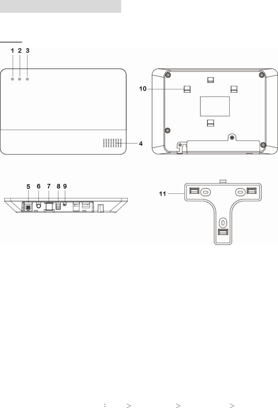
2.1. Identifying the parts:
Case A
1. Panel Status LED (Dual Colour - Red & Green)
RED LED ON - System in Arm Mode.
RED LED FLASHES - System in Home 1/2/3 Mode.
GREEN LED ON - System in Disarm Mode.
GREEN LED FLASHES - System in Learn Mode.
LED OFF - System in Walk Test Mode
2. Alarm & Fault Status LED (Dual Colour - Red & Yellow) (with display priority)
RED LED FLASHES - System is currently alarming.
RED LED ON - Alarm memory in system.
YELLOW LED FLASHES - AC Power failure.
YELLOW LED ON – Other fault condition (not including AC Power Failure ).
LED OFF – System normal.
LED Flashing Sequence Alarm Alarm Memory Panel AC failure Other Fault
3
3. Operational Status LED (Dual Colour - Yellow & Red) (with display priority)
YELLOW LED ON - Network error
LED OFF – Network ok
LED Flashing Sequence: Network ok Network error
4. Buzzer
5. Ethernet Port
6. Learn / Reset Button
7. Empty Port
8. DC Jack
For connecting the DC 12V, 1A
switching power.
9. Battery Switch
10. Tamper Switch
11. Wall Mounting Bracket
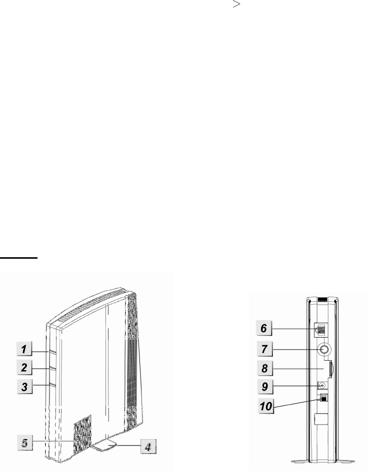
Case B
1. Panel Status LED (Dual Colour - Red & Green)
RED LED ON - System in Arm Mode.
RED LED FLASHES - System in Home 1/2/3 Mode.
GREEN LED ON - System in Disarm Mode.
GREEN LED FLASHES - System in Learn Mode.
LED OFF - System in Walk Test Mode
2. Alarm & Fault Status LED (Dual Colour - Red & Yellow) (with display priority)
RED LED FLASHES - System is currently alarming.
RED LED ON - Alarm memory in system.
YELLOW LED FLASHES - AC Power failure.

4
YELLOW LED ON – Other fault condition (not including AC Power Failure ).
LED OFF – System normal.
LED Flashing Sequence Alarm Alarm Memory Panel AC failure Other Fault
3. Operational Status LED (Dual Colour - Yellow & Red) (with display priority)
YELLOW LED ON - Network error
LED OFF – Network ok
LED Flashing Sequence: Network ok Network error
4. Standing Base
5. Internal Buzzer
6. Ethernet Port
7. Learn/Reset Button
8. Base
9. DC Jack
For connecting the DC 12V, 1A
switching power.
10. Battery Switch
2.2. The Power Supply:
An AC power adapter is required to connect to a wall outlet. Be sure only to use an adapter with
the appropriate AC voltage rating to prevent component damage. DC 12V 1A switching power
output adaptor is generally used to power the Control Panel for standard version.
Rechargeable Battery
In addition to the adapter, there is a rechargeable battery inside the Control Panel, which
serves as a back up in case of a power failure.
During normal operation, the AC power adapter is used to supply power to the Control
Panel and at the same time recharge the battery. It takes approximately 72 hours to fully
charge the battery.
<
<N
NO
OT
TE
E>
>
If the AC power is missing and the battery is near exhaustion, a low battery message
will be displayed and the internal siren will be disabled to conserve power.
5
2.3. System Requirements:
The system requires a TCP/IP network environment for MZ-1/8 IP Panel to be included in your
network.
To install the CD Wizard, your computer must have:
Microsoft Windows 98, ME, NT4.0, 2000, XP, Vista, 7 or 8 operating system.
Microsoft Internet Explorer 5.x, or later and Mozilla Firefox 1.0 compatible.
CD-ROM drive
CPU: Intel Pentium II 266MHz or above
Memory: 32MB (64MB recommended)
VGA resolution: 800x600 or above
6
3. Getting Started
Read this section of the manual to learn how to set up your MZ-1/8 Panel and program System
Settings over the Web page.
3.1. Hardware Installation for MZ-1/8
Step 1. Connect the Power Adaptor to a Wall Outlet and the other end to MZ-1/8. MZ-1/8 will
emit one short beep and Panel Status GREEN LED will turn ON.
Step 2. Connect the Ethernet cable as described below:
Step 2A: Plug-in the ethernet cable into the Internet jack on the Control Panel.
Step 2B: Plug-in the other end of the enclosed Internet cable into your Net Router port.
Step 2C: Once the Internet Set-up is successful, please leave the cable connected.
Step 3. Hardware installation for MZ-1/8 is now complete.
3.2. Software Installation for MZ-1/8
THIS INSTALLATION IS ONLY REQUIRED FOR FIRST TIME USER
1. RUNNING THE MZ-1/8 FINDER
To install the “Finder” software”
Step 1. Insert the supplied CD-ROM into your CD-ROM drive
Step 2. Find the Finder software in the CD-ROM
Step 3. Double click on the Finder to initiate the installation.
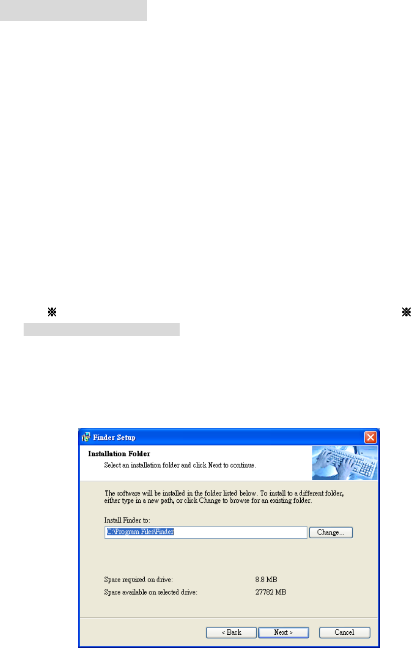
Step 5. Click “Change” to select the file folder, if no change is required; click “Next” to get
ready for the installation process.
7
Step 6. Click “Next” to begin the Installation. Once the installation is completed, click “Finish”
to confirm.
Step 7. A new icon will be displayed on your desktop.
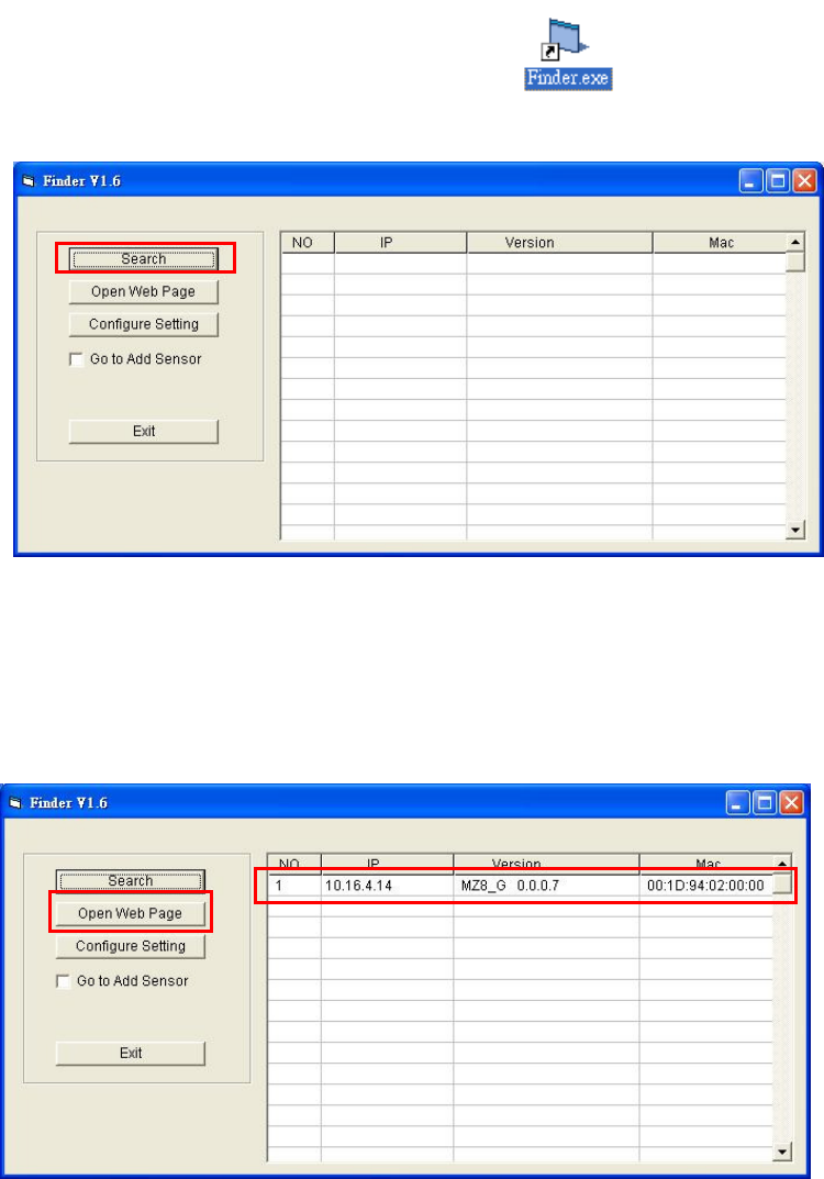
Step 8. Double click on the “Finder.exe” to start the installation. The following screen will be
displayed:
Step 9. Click on “Search”, It will start searching for recognized IP address within the Local
Network Service.
Step 10. You will be able to locate the current MZ-1/8 IP address among the list.
Displayed with MAC Address and Product version.
Step 11. Once MZ-1/8 is identified, select MZ-1/8 and click on “Open Web Page” to link to the
IP Security System Web page.
Step 12. Software installation for MZ-1/8 IP Panel is now completed.
8
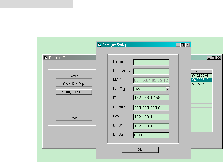
2. CONFIGURE SETTING
The Configure setting is for you to setup the network setting manually.
Step 1. Click on Configure Setting, the following window will display:
Step 2. Enter the network information and MZ-1/8’s web user name and password.
(Default) User Name: admin
(Default) Password: admin1234
Step 3. Click on OK to confirm. When the username and password are correct, a window will
display: Status: Configure success!!
9
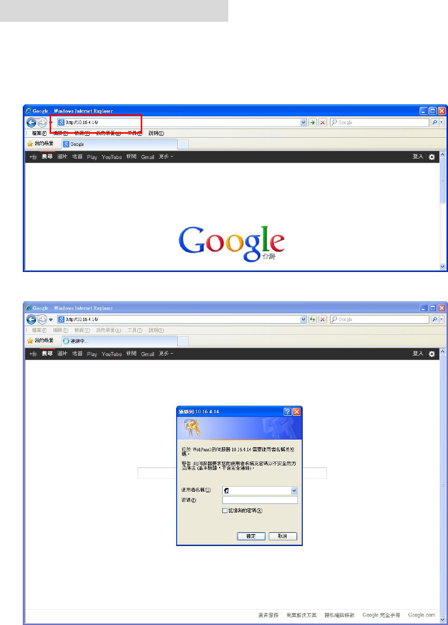
4. Connecting to Webpage
Step 1. Select MZ-1/8 in the Finder software and click on “Open Webpage” to connect to
MZ-1/8 webpage.
Alternatively, enter MZ-1/8 IP address displayed in Finder into your browser’s address
section and click “GO”.
Step 2. Enter the User name & Password.
Step 3. Enter the User name & Password and then press “OK”.
User Name: admin Password: admin1234
10
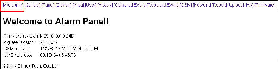
Step 4. You will enter the Control Panel webpage, the current Control Panel information will be
displayed.
11
5. SYSTEM SETTINGS
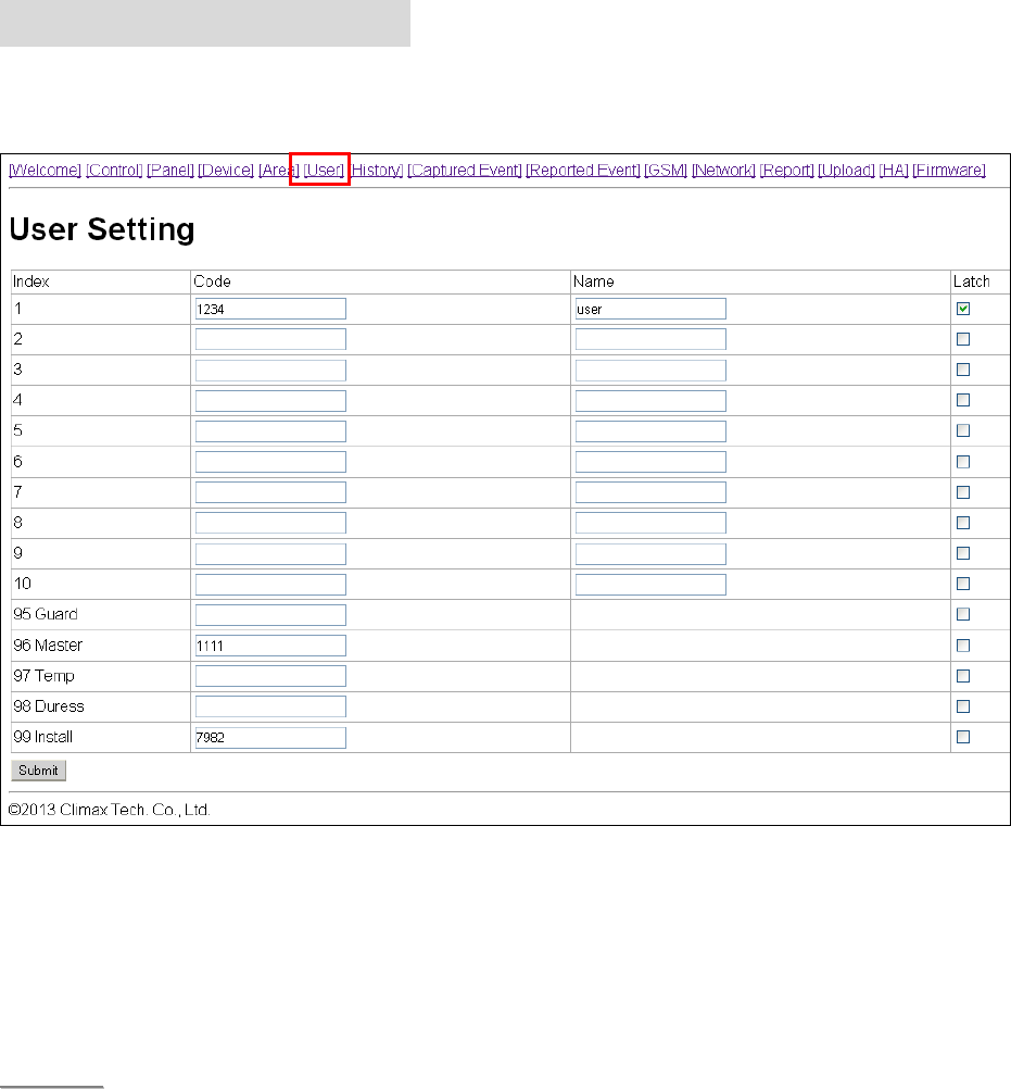
5.1. User
User Code
The User Codes are used for users to acess the alarm system. A total of 10 4-digit User
Codes can be stored in MZ-1/8. Each individual User can be given a name for easy
recognition when viewing system events.
User PIN code #1 is activated with “1234” as factory default. User PIN code #2~#10 are
deactivated by factory default
<
<N
NO
OT
TE
E>
>
When entering User PIN Codes with a Remote Keypad, if the wrong PIN Codes were
entered 5 times in 10 minutes, the Control Panel will prohibit further User PIN Code
entry for 15 minutes. All User PIN Codes entered during the 15 minute period will result
in error for the Remote Keypad.
Guard Code
The Guard Code is designed for security personnel to arm/disarm the system. When this
code is used for accessing the system, the Control Panel will record the event separately
from the User Codes.
The Guard Code consists of 4 digits and is not activated as default by the factory.
Master Code
This function is currently disabled
Factory default: 1111.

12
Temporary Code
The Temporary Code is used to access the system for a temporary user and is valid only
once per arming and once per disarming. Afterwards, the Temporary Code is
automatically erased and needs to be reset for a new Temporary user.
The Temporary Code consists of 4 digits and is not activated as default by the factory.
Duress Code
The Duress Code is used to access the system in duress situation. When this code is used
for accessing the system, the Control Panel will report a secret alarm message without
sounding the siren to the Central Monitoring Station to indicate of a “Duress Situation in
Progress”.
The Duress Code consists of 4 digits and is not activated by factory default.
Installer Code
The Installer Code is used for the installer to access the Control Panel via remote
command.
Factory default: 7982.
Latch Option
Whe the option is selected, the Control Panel will report all arming/disarming action by this
user.
Latch.
When the the Latch option box is ticked, the Latch option is turned ON.
To edit the Codes on Web Page:
Step 1. Key in your preferred 4-digit code
Step 2. Enter a name for the code (optional)
Step 2. Choose to tick On / Off the Latch Option box.
Step 3. Press “Submit” to confirm the new uploaded details.
13
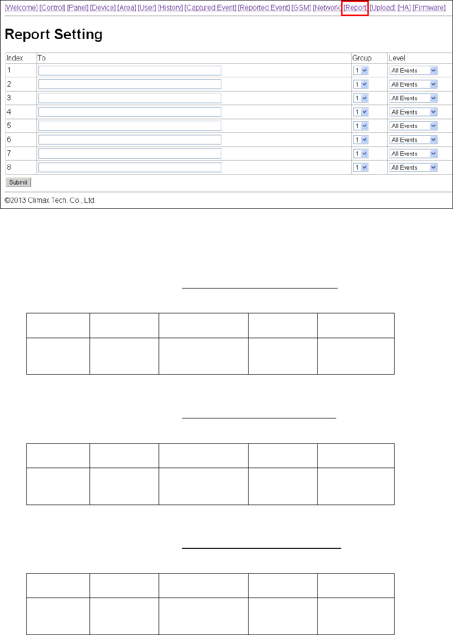
5.2. Report
This page is for you to enter the report destination setting. MZ-1/8 can store up to 8 report
destinations.
Reporting Type:
MZ-1/8 supports 5 reporting types:
IP/RF reporting in CID format:
Reporting destination format: ip://Account@Server IP:Port/CID
For Example: ip://6543@59.124.123.22:8765/CID
ip:// 6543 @59.124.123.23
:8765 /CID
Reporting
type
Account
(4-8 digits)
Server IP
address
Port
number
Reporting
Format
IP/RF reporting in SIA format:
Reporting destination format: ip://Account@Server IP:Port/SIA
For Example: ip://6543@59.124.123.22:8765/SIA
ip:// 6543 @59.124.123.23
:8765 /SIA
Reporting
type
Account
(4-8 digits)
Server IP
address
Port
number
Reporting
Format
IP/RF reporting in CSV format:
Reporting destination format: ip://Account@Server IP:Port/CSV
For Example: ip://6543@59.124.123.22:8765/SIA
ip:// 6543 @59.124.123.23
:8765 /CSV
Reporting
type
Account
(4-8 digits)
Server IP
address
Port
number
Reporting
Format

14
IP/RF reporting in CSV format with user name and password:
Reporting destination format: ip://Account@Server IP:Port/CSV/User/Password
For Example: ip://6543@59.124.123.22:8765/CSV/ABCD/1234
ip:// 6543 @59.124.123.23
:8765 /CSV /ABCD /1234
Reporting
type
Account
(4-8 digits)
Server IP
address
Port
number
Reporting
Format
User
Name
Passwo
rd
Reporting in format: (MZ-8 only)
Reporting destination format://Account@mobile number/CID
For Example: //1234@0926064587/CID
:// 1234 0926064587 /CID
Reporting
type
Account
(4-8 digits)
Mobile Number Reporting
Format
reporting in Text format: (MZ-8 only)
Reporting destination format:://mobile number/TEXT
For Example: /0926064587/TEXT
:// @0926064587 /TEXT
Reporting type Mobile Number Reporting Format
Digital reporting in format: (MZ-8 only)
Reporting destination format: // Account@Tel number
For Example: //1234@0926064587
// 1234 @27940001
Reporting type Account (4-8 digits)
Telephone Number
Email reporting
Reporting destination format: mailto: user@example.com
For Example: mailto: sales@climax.com.tw
mailto: sales@climax.com.tw
Reporting type Email Account
<
<N
NO
OT
TE
E>
>
Reporting type must be entered in lowercase letters
SMTP setting must be completed first for email reporting to function.
15
Groups:
You can assign reporting destinations to different groups, the reporting groups function
according to the following rules:
The reporting priority is based on to group number sequence. From Group 1 Group
Group 2 Group 3 ….etc
When more than one reporting destinations are assigned to a group, if a report is sent
to one of the detinations successfully, the system will stop reporting to the rest of the
reporting destination in the same group and move on to report to the next group.
If the Control Panel fails to send report to the first detination in a group, it will move on
to the next reporting destination. If all reporting destinations in the group cannot be
reached, the Control Panel will move on to the next group
If the Control Panel fails to report to all reporting groups, it will start reporting from group
1 and continue retrying until one report is made successfully.
16
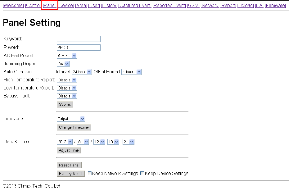
5.3. Panel
This page is for you to configure panel settings.
Keyword
The Keyword is used for receiving commands from users. When a user sends a command
to the Control Panel, the correct keyword must be entered along with a valid User PIN
code for the Control Panel to recognize the command. The Keyword is disabled by default.
(MZ-8 only)
P-word
The P-word is also used for receiving commands from Installers. When an installer sends
a command to the Control Panel, the correct P-word must be entered along with Installer
code for the Control Panel to recognize the command. The P-word is “PROG” by default.
(MZ-8 only)
AC Fail Report
This is for you to set the waiting time for the Control Panel to make report after detecting
AC failure. Factory default is set to 5 minutes.
Jamming Report
This is for you to set whether the Control Panel should detect radio frequency interference
and make report when interference is detected. Factory default is set to On. When radio
jamming is detected, the Control Panel will report the event accordingly.
Auto Check-in
This is for you to set the interval time the Control Panel waits before making a regular
check-in report
17
Interval: Set the interval waiting time
Offset Period: This is to set the time delay before the first “Auto Check-in Report”
report to be made. For example, if “Offset” time period is set to 2 Hours, then the
Control Panel will make the first “Auto Check-in Report” report after 2 hours,
High Temp.
This is for you to set the High Temperature reporting threshold. If the Control Panel has
learnt in a Temperature Sensor, it will make High Temperature report and raise alarm when
the temperature exceeds the threshold. When the temperature drops below set value
again, the Control Panel will stop alarming and send High Temperature Restore report.
Factory default is set to Disable.
Low Temp
This is for you to set the Low Temperature reporting threshold. If the Control Panel has
learnt in a Temperature Sensor, it will make Low Temperature report and raise alarm when
the temperature drops below the threshold. When the temperature rises above set value
again, the Control Panel will stop alarming and send Low Temperature Restore report.
Factory default is set to Disable.
Bypass Fault:
This is for you to set whether you want to ignore fault events regarding Ethernet or RF
function. Bypassed fault events will not displayed under Control webpage or cause the
fault LED will to light up and emit beeps. Please refer to 9. Panel Control for more
information regarding system fault event management.
IP: When IP is selected, Ethernet related faults will be ignored.
RF: When RF is selected, RF related faults will be ignored.
Factory default is set to Disable.
After finishing the above settings, press “Submit” to confirm the change.
Time Zone
This is for you to set your Time Zone.
Date & Time
This is for you to set your current date and time.
After finishing Time Zone and Date/Time setting, press “Adjust Time” to confirm the change.
Reset
Press the “Reset” button to restart the Control Panel.
Factory Reset
Press the “Factory Reset” button to clear all stored information and settings in the Control
Panel, all settings will be returned to factory default. You can choose to tick the box for
“Keep Network Setting” or “Keep Device Setting” before pressing Factory Reset to keep
part of the settings unchanged.
18
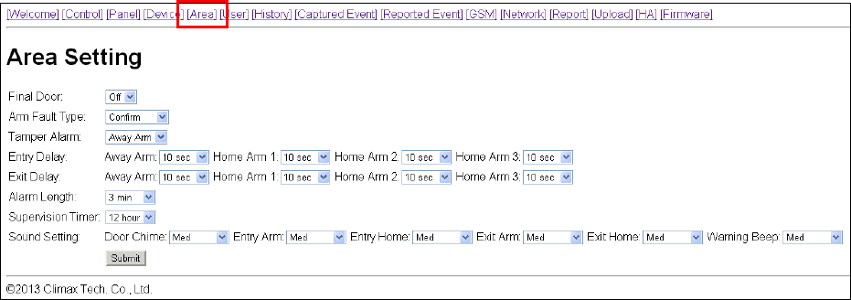
5.4. Area
This page is for you to configure area settings.
Final Door
Final Door On: When the system is Away Armed with a Door Contact set to Entry
attribute, the system will automatically arm the system once the Door Contact is closed
even if the entry delay timer has not expired yet.
Final Door Off: When the system is Away Armed with a Door Contact set to Entry
attribute, the system will only arm the system after the entry delay timer expires.
Factory Default is set to Final Door Off.
Arm Fault Type
Confirm: When set to Confirm, If you attempt to arm when a fault exists within the
system, the arming action will be prohibited, and a message will be displayed “Fault
exists! Please Confirm!” You need to arm the system again to confirm your action and
arm the system. (Factory Default)
Direct Arm: When set to Direct Arm, If you attempt to arm when a fault exists within
the system, the system will enter selected arm mode without further notification about
fault events.
Factory Default is set to Confirm.
Tamper Alarm
Away Arm: Tamper alarm will only be activated when tamper switch is triggered under
Away Arm mode (Tamper event will still be reported normally in Home/Disarm mode).
Always: Tamper alarm will be activated whenever tamper switch is triggered.
Factory Default is set to Away Arm.
Entry Delay
Set the Entry Delay Timer for Away Arm, Home Arm 1, Home Arm 2, and Home Arm 3
modes. When a device set to Entry attribute is triggered under arm mode, the Entry Delay
Timer will begin to countdown. The system must be disarmed before the timer expires or
an alarm will be activated.
19
Factory default is set to 10 seconds.
Exit Delay
Set the Exit Delay Timer for Away Arm, Home Arm 1, Home Arm 2, and Home Arm 3
modes. When you arm the system, the system will enter your selected arm mode after the
Exit Delay Timer expires
Factory default is set to 10 seconds.
Alarm Length
When an alarm is activated, both the Control Panel siren and external siren will raise
alarm according to the Alarm Length setting.
Factory default is set to 3 minutes.
Supervision Timer
Set the supervision timer for accessory devices, if no supervision signal is received within
set duration for a certain device, the Control Panel will report the situation accordingly.
Factory default is set to 12 hour.
Sound Setting
Door Chime: If not disabled, the Control Panel will sound a door chime sound when a
Door Contact set to Entry attribute is activated in Disarm mode. .
Entry Arm: If not disabled, the Control Panel will sound beeping sounds when a Door
Contact set to Entry attribute is activated in Away Arm mode. .
Entry Home: If not disabled, the Control Panel will sound beeping sounds when a Door
Contact set to Entry attribute is activated in Home Arm mode. .
Exit Arm: If not disabled, the Control Panel will sound beeping sounds when during
Exit Delay Timer for Away Arm mode.
Exit Home: If not disabled, the Control Panel will sound beeping sounds when during
Exit Delay Timer for Away Arm mode.
Warning Beep: If not disabled, the Control Panel will sound beeping sounds every 30
seconds when fault exists within system.
20
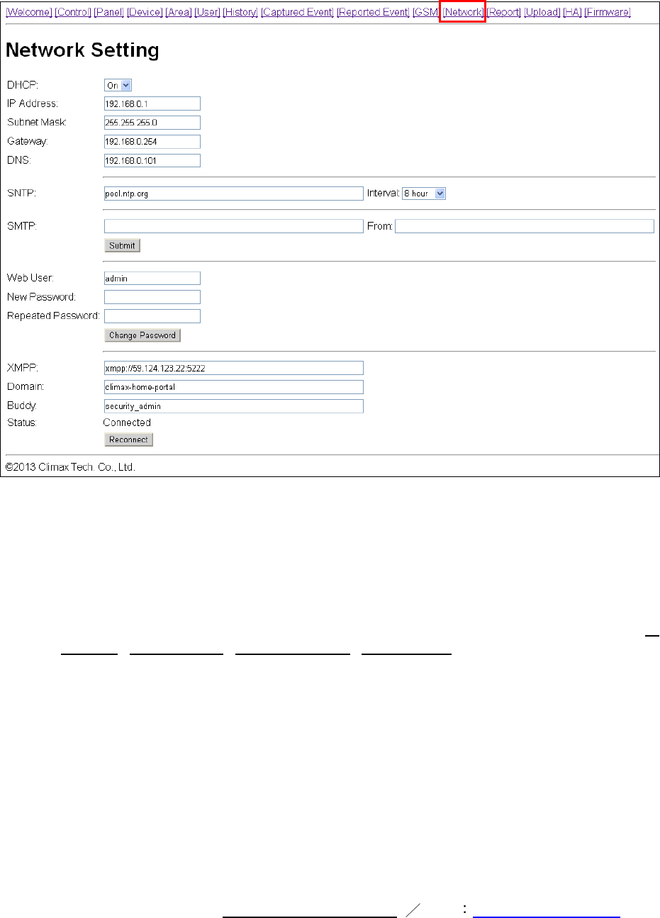
5.5. Network
This page is for you to configure network settings.
DHCP
On: If DHCP is set to On, the Network will obtain the IP address automatically with a
valid Network DHCP Server. Therefore, you won’t need to do any settings. You can
only set DHCP to On if your Network environment supports DHCP. It will automatically
generate all information.
Off: If DHCP is set to Off, you neet to enter the Network information manually for IP
Address, Subnet mask, Default gateway, Default DNS. Please make sure that you
have obtained all required values according to your Network environment. Please
contact your local service provider for more information.
SNTP
SNTP setting is for you to enter an internet time server to synchronize and update Control
Panel time automatically according to set interval times
SMTP
SMTP setting is for you to program the mail server related settings. The email account you
set here would be used to make report or email the triggered images/videos from PIR
Camera/Video Camera. For email destination, please refer to Report or Upload section.
SMTP format: smtp://user:password@example.com From name@example.com

21
<
<N
NO
OT
TE
E>
>
SMTP setting must be entered in all lowercase letters
MZ-1/3/8 does not support SMTP encryption method such as SSL or TLS.
Administrator Account Setting
Here you can program the user name and password used for accessing the webpage.
Web User: This is the user name you entered when you access the panel webpage.
Default web user is “admin”. If you want to change the user name, enter a new name in
the field. Maximum character allowed is 20.
New Password: If you want to change the password, enter the password in this field.
Maximum character allowed is 20.
Repeat Password: Repeat the password again in this field
After finishing above settings, click “Submit” to update settings.
XMPP
XMPP setting enables the Control Panel to query the set destination. This setting is
required for the Control Panel to connect to Climax’s Home Portal Server for further
remote control.
XMPP: server address. ex: xmpp://user:password@example.com
Domain: domain address
Buddy List: contact destination
<
<N
NO
OT
TE
E>
>
XMPP setting must be entered in all lowercase letters
22
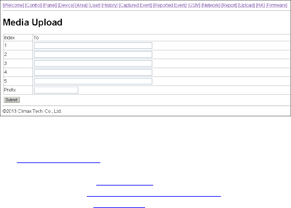
5.6. Upload
This page is for you to set upload destination for captured pictures and videos from PIR Camera
and PIR Video Camera.
1~5
Enter an email address, FTP address, server address, or mobile number for MMS delivery
For email delivery, the SMTP setting under Network must be completed. The format is:
mailto: user@example.com
For MMS delivery to mobile phone (MZ-8 only), the MMS setting under RF must be
completed. The format is: mms: 0987654321
For FTP, the format is: ftp://user.password@example.com:port/path
For server, the format is: http://ip:port/path
Prefix
Specify a prefix to be titled for every captured picture/video file.
23
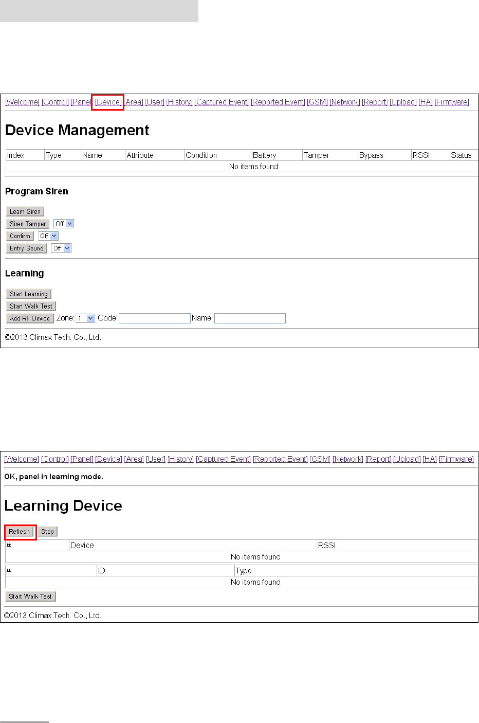
6. Device Management
This page for you to learn in, edit, delete and control all the accessory devices. A total of 40
devices are allowed to be learnt in to the system, including RF and ZigBee devices. Only 6 PIR
Cameras (VST-852/VST-852 Pro) or Video Camera (VST-873/VST-873Pro) can be learnt into
the system.
6.1. Learning
Step1. Under Disarm Mode, press “Start Learning”. The Control Panel will enter learning
webpage. The Control Panel LED 1 will flash green.
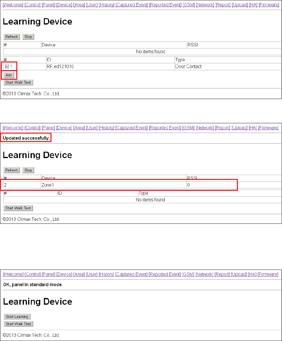
Step2. Press the learn button on your device, for ZigBee device, press and hold the learn button
for about 10 seconds (please refer to device manual for detail) to transmit a learn code.
Step3. If the Control Panel receives the learn code it will emit 2 short beeps, click the “Refresh”
button to display the device information on webpage. If the Control Panel emit 1 long
beep instead, it means the device has already been learned into the Control Panel.
<
<N
NO
OT
TE
E>
>
If the Control emits 2 short beep when learning in ZigBee sensors, but does not display
24
device information when you refresh the page, it means the Control Panel received
supervision code from the sensor instead of learn code. Please resend the learn code
again.
Step4. Tick the device # box, then click “Add” to include the device in the Control Panel.
Step5. The Control Panel will display “Updated Successfully” message and the new learned in
device zone accordingly. The device is now learn in to the system.
Step6. You can click “Stop” button to leave learning mode, the Control Panel will return to
normal mode.
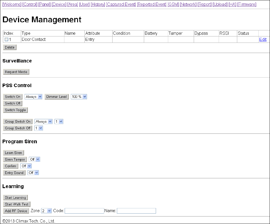
25
Step7. After learning a device into the Control Panel, the Device Webpage will be changed to list
all available functions.
Local Learning: The Control Panel feature local learning function for you to learn in the
device without using the webpage
Step1. Press and hold the learning button on the back of Control Panel for 10 seconds and
release when you hear a beep. The LED 1 will begin to flash green to indicate the
Control Panel is in learning mode.
Step2. Press the learn button on your devices to transmit a learn code, if the Control Panel
receives the learn code, it will emit two beeps to indicated. The devices will be added
into the Control Panel automatically.
Step3. After finish learning devices, press and hold the learn button on the back of Control Panel
until the Control Panel emits 2 beeps to leave learning mode.
Step4. Proceed to edit the device settings in the Control Panel Device webpage.
26
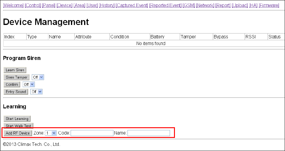
6.2. Add Device
For RF devices, you can also add device into the Control Panel by entering the device’s RF
code. (This function cannot be used with ZigBee devices)
Step1. Select the zone number you want to assign the new device to
Step2. Enter the device’s RF code
Step3. Enter device name.
Step4. Click “Add RF Device ” to include the device in the system.
27
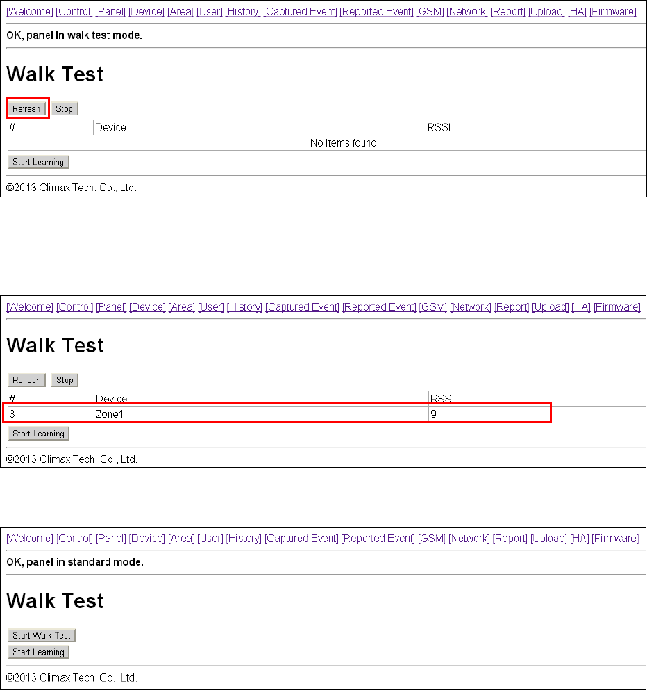
6.3. Walk Test
Step1. Press “Start Walk Test” under either Learning or Device Management webpage. The
Control Panel will enter Walk Test page.
Step2. Press the learn button on your device (please refer to device manual for detail) to
transmit a test code.
Step3. If the Control Panel receives the test code, it will emit a long beep, click the “Refresh”
button to displayed accordingly on the webpage.
Step4. You can click “Stop” button to terminate walk test, the Control Panel will return to normal
mode.
28
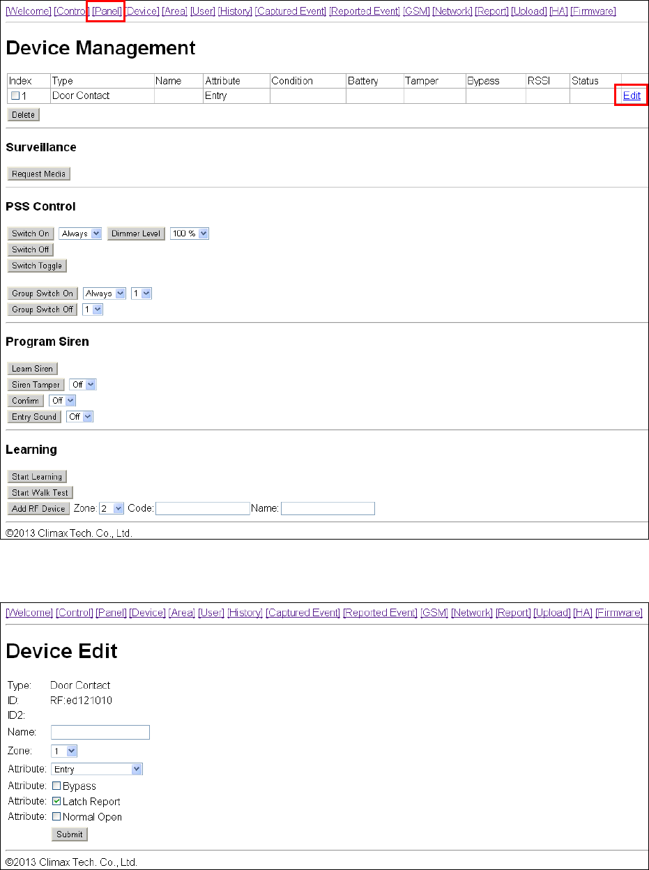
6.4. Edit Device
After you learn in a device to the system, you should proceed to edit its setting.
Step1. Under Device Management webpage, click “Edit”. The Control Panel will enter device
editing page.
Step2. Proceed to edit device settings, click “Submit” when you are satisfied with all settings or
information..

29
Name: Enter a name for the device, A maximum of 20 characters are allowed
Zone: Select the device zone number.
Attribute:
For Door Contact you are requested to select the device attribute from Burglar, Home
Omit, Home 1/2 Omit, Home 1/3 Omit, Home Access, Delay Zone, Away Only,
Entry, Away Entry, 24 Hr, Fire, Medical Emergency, Water, Set/Unset Silent Panic,
Personal Attack.
For PIR Sensor, you are requested to select the device attribute from Burglar, Home
Omit, Home 1/2 Omit, Home 1/3 Omit, Home Access, Delay Zone or Entry Zone.
For Remote Controller, you are requested to select the device attribute from Silent
Panick or Personal Attack.
Attribute List:
Burglar
When the system is in any Arm mode, if a “Burglar” device is triggered, a
“Burglar Alarm” will be activated immediately and reported.
Home Omit
When the system is in Home Arm 1/2/3 mode, if a “Home Omit” device is
triggered, the Control Panel will not raise alarm. It will still send a report for this
event
When the system is in Full Arm mode, if a “Home Omit” device is triggered, the
Control Panel will respond in the same way as if a “Burglar” device is triggered.
Home 1/2 Omit
When the system is in Home Arm 1/2 mode, if a “Home 1/2 Omit” device is
triggered, the Control Panel will not respond. It will still send a report for this event
When the system is in Away Arm or Home Arm 3 mode, if a “Home 1/2 Omit”
device is triggered, the Control Panel will respond in the same way as if a
“Burglar” device is triggered.
Home 1/3 Omit
When the system is in Home Arm 1/3 mode, if a “Home 1/3 Omit” device is
triggered, the Control Panel will not respond. It will still send a report for this event
When the system is in Away Arm or Home Arm 2 mode, if a “Home 1/2 Omit”
device is triggered, the Control Panel will respond in the same way as if a
“Burglar” device is triggered.
Home Access
When the system is in Home mode, if a “Home Access” device is triggered, the
Control Panel will start an Entry Delay period to give enough time to disarm the
system. It will also send a report for this event
When the system is in Full Arm mode, if a “Home Access” device is triggered,
the Control Panel will start a Burglar Alarm and a burglar message will be
reported.
Delay Zone
When the system is in any Arm mode, if a “Delay Zone” device is triggered, a
“Burglar Alarm” will be activated immediately and reported.

30
When the system is in any Armed mode, and the Control Panel is counting down
the Entry Delay, if a “Burglar” device is triggered, the Control Panel will not
respond.
During the Exit Delay period, if a “Burglar” device is triggered, the Control Panel
will not respond .
Away Only
When the system is in Away Arm mode, if an “Away Only” device is triggered, a
“Burglar Alarm” will be activated immediately and reported.
When the system is in any Home Arm mode, if an “Away Only” device is
triggered, the Control Panel will not respond.
During the Entry Delay or Exit Delay period, if an “Away Only” device is triggered,
the Control Panel will not respond .
Entry
When the system is in any Arm mode, if an “Entry” device is triggered, the
Control Panel will start an Entry Delay countdown timer for the user to disarm the
system.
After the delay period has expired and no correct PIN code has been entered, the
Control Panel will activate a “Burglar Alarm” and the event will be reported.
When the system is in Disarm mode, if a “Entry” is triggered, the Control Panel
will make a “ding-dong” Door Chime sound (if Door Chime function is not
disabled).
Away Entry
When the system is in Away Arm, if an “Away Entry” device is triggered, the
Control Panel will start an Entry Delay countdown timer for the user to disarm the
system.
After the delay period has expired and no correct PIN code has been entered, the
Control Panel will activate a “Burglar Alarm” and the event will be reported.
When the system is in Disarm mode, if a “Entry” is triggered, the Control Panel
will make a “ding-dong” Door Chime sound (if Door Chime function is not
disabled).
When the system is in any Home Arm mode, if an “Away Entry” device is
triggered, the Control Panel will not respond.
During the Entry Delay or Exit Delay period, if an Away Entry device is triggered,
the Control Panel will not respond
24 Hour
The 24 Hour device is active all the time and does not have to be armed or
disarmed. An Event Code of #130 will be reported with trigger.
Fire
The Fire device is active all the time and does not have to be armed or disarmed.
An Event Code of #111 will be reported with trigger.
Medical Emergency
A Medical Emergency device is active all the time and does not have to be
armed or disarmed. An Event Code of #101 will be reported with trigger.

31
Water
The Water device is active all the time and does not have to be armed or
disarmed. An Event Code of #154 will be reported with trigger.
Set/Unset (For Door Contact Only)
If the Door Contact is set to Set/Unset, the system will be disarmed when the
Door Contract is triggered, and armed when Door Contact is closed.
<
<N
NO
OT
TE
E>
>
Please refer to Normal Open/Normal Close section below for further detail.
Silent Panic
If the device attribute is set as Silent Panic, when the device is activated, the
Control Panel will report a Slient Panic alarm without sounding an audible siren.
An event code of 122 will be reported.
Personal Attack
If the device attribute is set as Personal Attack, when the device is activated, the
Control Panel will activate an alarm and report an event code of 120 will be
reported.
Bypass: If Bypass is selected, the device will be deactivated. When a bypassed device
is triggered, the Control Panel will not raise alarm.
Latch Report: If Latch Report is selected, the Control Panel will send report when the
device is triggered.
Normal Open: This option is only available for Door Contact:
If Normal Open is selected, the Door Contact will be triggered when it is closed.
If Normal Open is selected, the Door Contact will be triggered when it is opened.
Group: This option is only available for Power Switch. You can assign multiple Power
Switches to a group and control the group together
<
<N
NO
OT
TE
E>
>
To avoid accidental tamper trigger, when you are changing device batteries or moving
device locations, be sure to use the Bypass function to temporarily deactivate the
device.
6.5. Delete Device
In order to remove devices from the Control Panel, check the number boxes before the device
name, then click Delete, the selected devices will be removed.
6.6. Request Media
You can manually control the selected PIR Camera and PIR Video Camera to take a picture or
record a 10-second video clip. The requested picture and video clip can be viewed in “Captured
Event” webpage.

32
6.7. Power Switch Control
This section is for you to control Power Switch in the system
Switch On: Select the desired Power Switch, then choose the time length you want to
turn on the Power Switch, then click “Switch On” to confirm.
Switch Off: Select the desired Power Switch, then click “Switch Off” to turn off.
Switch Toggle: Select the desired Power Switch, the click “Switch Toggle.” If the Power
Switch is on, it will be turned off; if the Power Switch is off, it will be turned on instead.
Switch Level (%): This function is for Power Switch with Dimmer function only. Select the
desired Power Switch with Dimmer, then choose the power level percentage you want to
adjust. Click “Switch Level %” to confirm the change.
Group Switch On: You can control Power Switches assgined to one group together.
Select the desired Power Switch group, then choose the time length you want to turn on
the Power Switches, then click “Group Switch On” to confirm.
Group Switch Off: Select the desired Power Switch group, then click “Group Switch Off”
to turn off.
6.8. Siren Learning/Control
This section is for you to learn in Indoor Siren or Outdoor Bell Box, and edit their settings.
Learn Siren: To learn in siren:
1. Put the siren into learning mode (Please refer to siren manual for detail)
2. Click “Learn Siren” to transmit a learn code.
3. Refer to siren manual to complete the learn in process.
Siren Tamper: This is for you to enable/disable the siren tamper protection.
Select On/Off, then click “Siren Tamper” to confirm setting.
Confirm: This is for you to set whether the siren should emit beeping sound when the
system is armed or disarmed.
Select On/Off, then click “Confirm” to confirm setting.
Entry Sound: This is for you to set whether the siren should beep warning sound during
Entry Delay coundown timer.
Select On/Off, then click “Confirm” to confirm setting.
<
<N
NO
OT
TE
E>
>
When you are changing Siren batteries or moving Siren mounting location, you need to
first deactivate the siren by selecting Bypass is siren edit screen, then turn off the Siren
Tamper to avoid accidental tamper trigger.
33
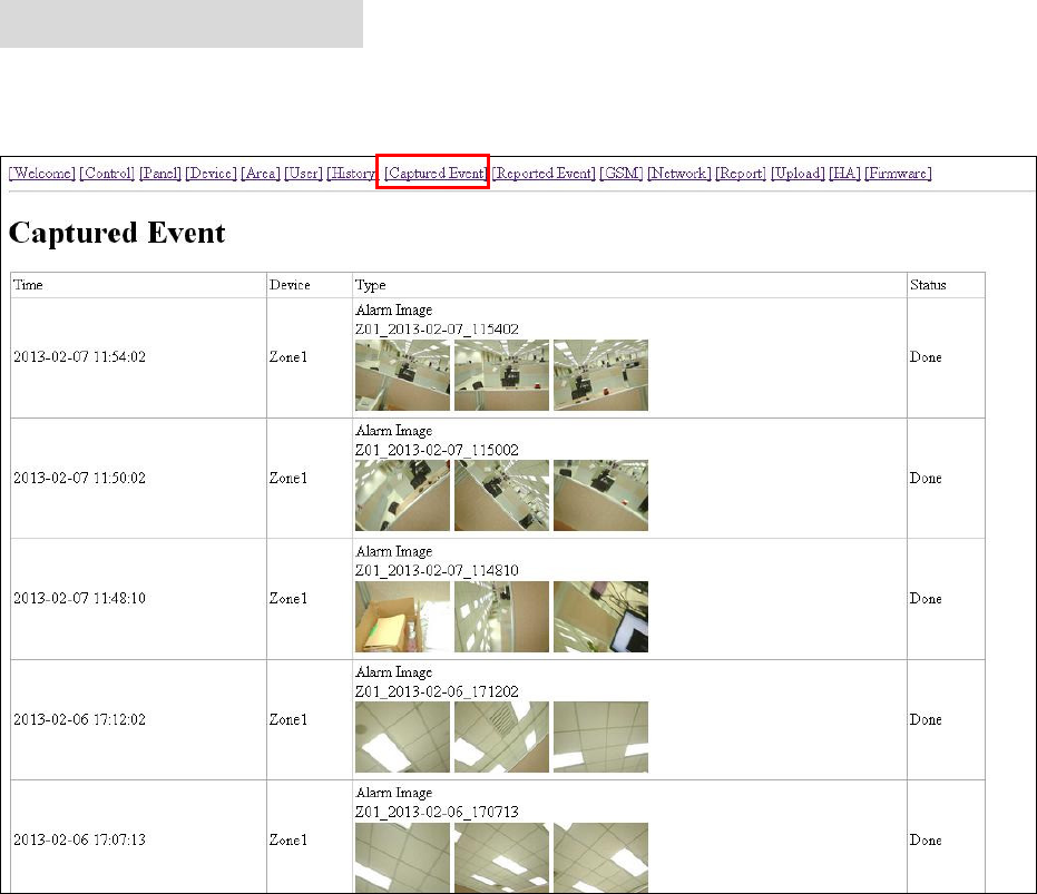
7. Captured Events
Pictures/Videos captured by PIR Camera and PIR Video Cameras will be displayed in this page.
Only the pictures/videos of the 6 latest events will be stored.
Click on the image or video to view the file.
Time: The time when the picture/video is captured.
Device: The Zone number of the PIR Camera/Video Camera triggered.
Type: The type of the image/video.
Alarm Image: When triggered under Away Arm/Home Arm mode, the PIR Camera will
take three pictures.
Requested Image: You can manually request the PIR Camera to take one picture.
Alarm Video: When triggered under Away Arm/Home Arm mode, the PIR Video
Camera will record a 10-second video clip.
Requested Video: You can manually request the PIR Video Camera to take a
10-second clip.
Status: The staus of the captured event are listed as follows:
Waiting for Media Ready: The PIR Camera/Video Camera has captured image/video
and will send the image video to Control Panel after the file is ready. For Alarm
Image/Video, if you disarm the Control Panel under this status, the captured
image/video will be deleted and no image/picture will be sent.

34
Waiting for Capture: The PIR Camera/Video Camera is sending captured
picture/video the the Control Panel. For Alarm Image/Video, if you disarm the Control
Panel under this status, the captured image/video will be deleted and no image/picture
will be sent.
Upload: The PIR Camera/Video Camera has finished sending image/picture to Control
Panel. The Control Panel is now uploading the image/video to programmed destination.
Done: The Control Panel has finished uploading image/video successfully
Fail: The PIR Camera/Video Camera was unable to send captured image/picture to
Control Panel. Please check if the PIR Camera/Video Camera is out of order or under
Low Battery, then perform Walk Test to check signal strength.
Timeout: The PIR Camera/Video Camera did not respond to Control Panel. Please
check if the PIR Camera/Video Camera is out of order or under Low Battery, then
perform Walk Test to check signal strength.
<
<N
NO
OT
TE
E>
>
If a PIR Camera/Video Camera is triggered when the system is armed. Do not disarm
the alarm system before the status displays “Upload” or “Done.” Otherwise the
image/video will be deleted and will not be sent to Control Panel.
35
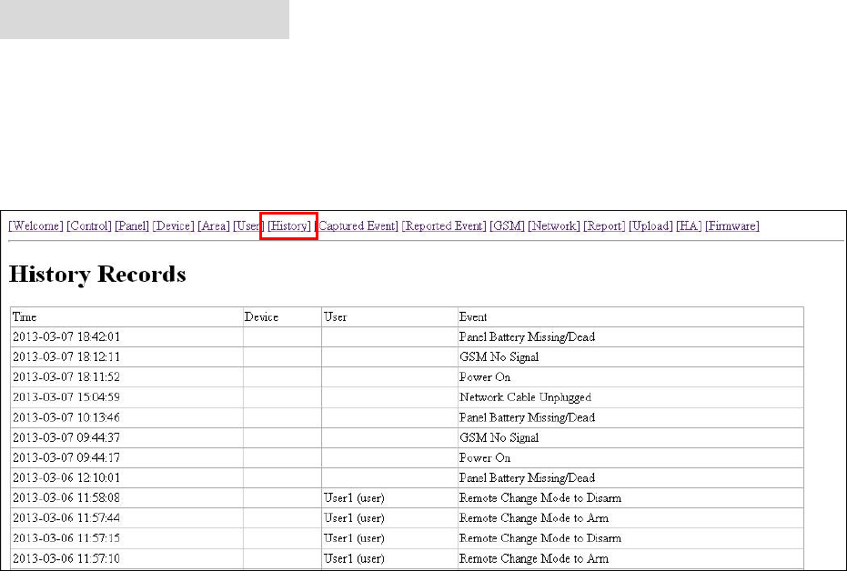
8. History Records
8.1. History
The Control Panel history events are recorded in this page.
The History memorizes the last 50 Panel events including:
All Alarm Events with Device Zone-
All Fault Warning Events from Panel or Device
All Arming And Disarming Events by Panel and Remote Controller
All Arming and Disarming Events by Remote Keypad with User
information.
Time: The time when the event take place
Device : The device that triggered the event
User: The user who perform the event action
Event: The event content
36
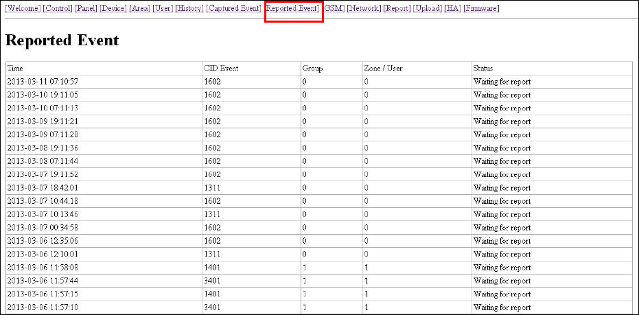
8.2. Reported Event
The reported event history are recorded in this page..
A total of 50 reported events can be recorded with Time, CID Event Code, Device Group/Zone
and User information.
Time: The time when the Control Panel begins the report
CID Event Code Format:
The CID event code is recorded in 4 digits format of “Prefix + Event Code”
Prefix: “1” represents events taking place. “3” represents event restore.
Event Code: 3-digit CID event code.
For Example: “1302” means “Low Battery”, and “3302” means “Low Battery Restore.”
Group: The group the device belongs to
Zone/User:
For arming/disarming, the User PIN # will be displayed.
For device triggering, the device zone will be displayed.
37
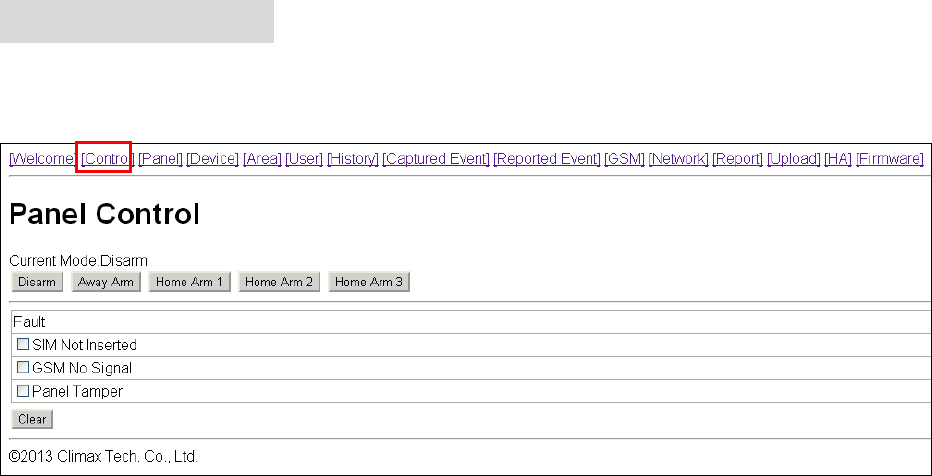
9. Panel Control
Under this page, you can choose to Away Arm, Home Arm 1/2/3, or Disarm the system. If any
fault exists within the system, they will be displayed under this page.
Current Mode
Control Panel current mode.
Away Arm:
Away Arm will arm all devices in the system.
Home Arm 1/2/3:
You can choose to arm the system in 3 different Home Arm mode.
Under Home Arm 1, device set to Home Omit, Home 1/2 Omit or
Home 1/3 Omit will not raise an alarm when triggered.
Under Home Arm 2, device set to Home Omit or Home 1/2 Omit will
not raise an alarm when triggered.
Under Home Arm 3, device set to Home Omit or Home 1/3 Omit will
not raise an alarm when triggered.
Fault Events
Fault events in system are listed in the Fault section. If you try to arm the system when
fault event exists a warning message “Fault Exists! Please Confirm!” will be displayed to
notify you. You will need to arm the system again to force arm the system. Alternatively,
you can select the fault events and click “Clear” to ignore the fault events. Cleared fault
event will no longer prevent you from arming the system.
If all fault events are cleared, the fault LED will no longer light up or flash.
38
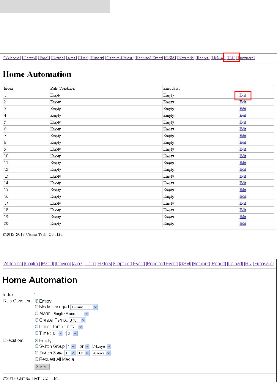
10. Home Automation
This page is for you to setup Home Automation rules with condition and execution setting to
control the alarm system or home appliance automatically. A total of 20 Home Automation rules
are available for setting.
Step1. Click “Edit” to configure setting for the selected rule number. You will enter edit page.
Step2. Set the Rule Condition.
Mode Changed: The rule will be activated when the system mode is change to set mode.
Alarm: The rule will be activated when the set alarm event is triggered.
39
Greater Temp: The rule will be activated when the temperature rises above set value.
Lower Temp: The rule will be activated when the temperature drops below set value.
Timer: The rule will be activated when system reaches set time
Step3. Set the Execution Rule
Switch Group: All Power Switches in selected group will be turned On/Off for set duration
according to your setting.
Switch Zone: All Power Switches in selected zone will be turned On/Off for set duration
according to your setting.
Request All Media: All PIR Camera/Video Camera in the alarm system will be requested
to take a picture or record a 10-second video clip.
Step4. Click “Submit” to confirm the rule change.
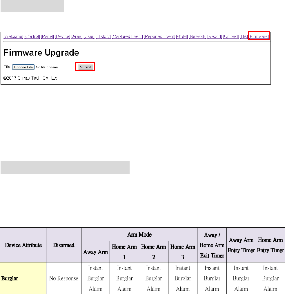
11. Firmware
This page is for you update your Control Panel firmware.
Step1. Select the firmware file in your computer
Step2. Click “Submit” to upload the firmware file to Control Panel.
Step3. It takes several minutes to complete update, do NOT power off during the process.
Step4. Once updating is complete, the Control Panel will reboot automatically.
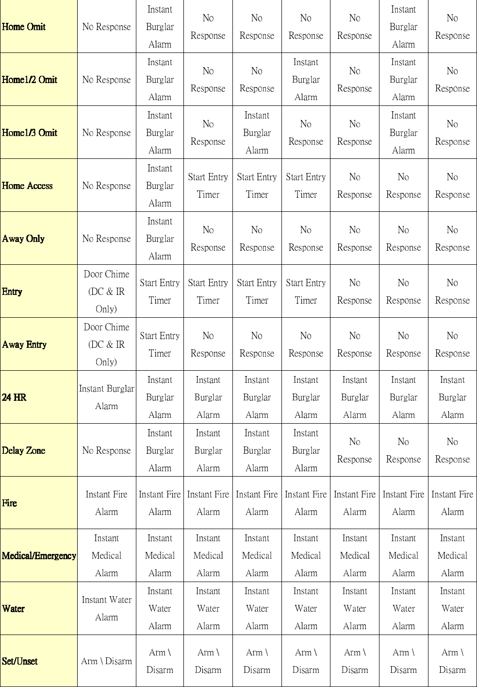
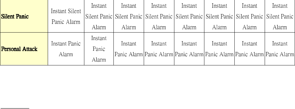
12. Alarm Activation Table
For Alarm Activation by Events and Control Panel Responses, please refer to the following
table:
Control Panel Mode & Response Table
40
41
Press “Save”. A message edit screen will appear for you to confirm. Press “Send” to send
the command to panel.
<
<N
NO
OT
TE
E>
>
For system mode change (Arm, Home, Disarm), the Power Switch Ggroup selection is
limited to #1 only.
For High/Low Temperature and Time setting. You can select any Power Switch group
from #1 ~ #4.

42
14. Event Code
The events are reported with a qualifier before the event code. The qualifier “1” means the event
has taken place, “3” means the event has been restored. For example, if the Control Panel
reports “1302”, it means the panel is under low battery; if the Control Panel reports “3302”. It
means the panel low battery condition has been restored.
100 – Medical
101 – Personal emergency
When the Wrist Transmitter / Emergency Pendant (WTR) is pressed.
102 – Inactive
110 – Fire
111 – Smoke
When the Smoke Detector (SD) is triggered.
114 – Heat
When the Heat Detector (HD) is triggered.
120 – Panic
When the Panic Button of the Remote Controller (RC) is pressed.
121 – Duress
When the Duress Code is entered to disarm or arm the system.
122 – Silent Panic
When the panic button on a Remote Controller (RC) set to silent panic is pressed.
130 – Burglar
When any one of the following devices is triggered:
The Door Contact (DC) set at Burglar (@ B)
The Door Contact (DC) set at 24 Hours (@ H)
The Door Contact (DC) set at Delay (@ D)
The PIR set at Burglar (@ B)
The PIR set at Delay (@ D)
131 – Burglar Perimeter
When a device set as Entry is triggered in away arm mode.
132 – Burglar Interior
When a device set at Entry is triggered in the home mode.
137 – Panel Tamper
When the Control Panel tamper switch is triggered.
147 – Sensor Supervision Failure
When MZ-1/8 fails to receive the signal transmitted from any one of the devices
individually for a preset period.
151 – Gas
154 – Water leakage
When a Water Sensor or Door Contact set as Water is triggered.
43
158 – High Temperature
When the temperature exceeds High Temperature setting.
159 – Low Temperature
When the temperature drops below Low Temperature setting.
162 – CO detector
301 – AC Failure
When the AC power fails for more than 10 sec.
302 – Low Battery
When the Control Panel is under low battery.
311 – Panel Battery Missing/Dead
When the Control Panel Battery is missing or disconnected.
344 – Interference
374 – Arm with Fault
When fault exists in system, and the system is armed by confirming the arm action.
(Arm Fault Type set to Confirm.)
383 – Device Tamper
When a device’s tamper switch is triggered.
384 – Device Low Battery
When a device’s is under low battery.
389 – Self Test Failure
400 – Arm/Disarm (by Remote Controller)
When the system is armed or disarmed by using the Remote Controller.
401 – Arm/Disarm by Panel
When the system is armed or disarmed by entering the PIN code.
408 – Set/Unset Disarm
407 – Disarm/Away Arm/Home Arm by Remote Keypad
456 – Home Arm
465 – Alarm Reset
570 – Zone Bypass
When fault exists in system, and the system is armed by ignoring the fault event. (Arm
Fault Type set to Direct Arm)
602 – Periodic test report
When MZ-1/8 makes periodic Check-in reporting.
This device complies with Part 15 of the FCC Rules. Operation is subject to the following two
conditions:
(1) This device may not cause harmful interference, and
(2) This device must accept any interference received, including interference that may cause
undesired operation.