Climax Technology Co SRZB Indoor Siren User Manual SR 32ZBS 20160627 FCC
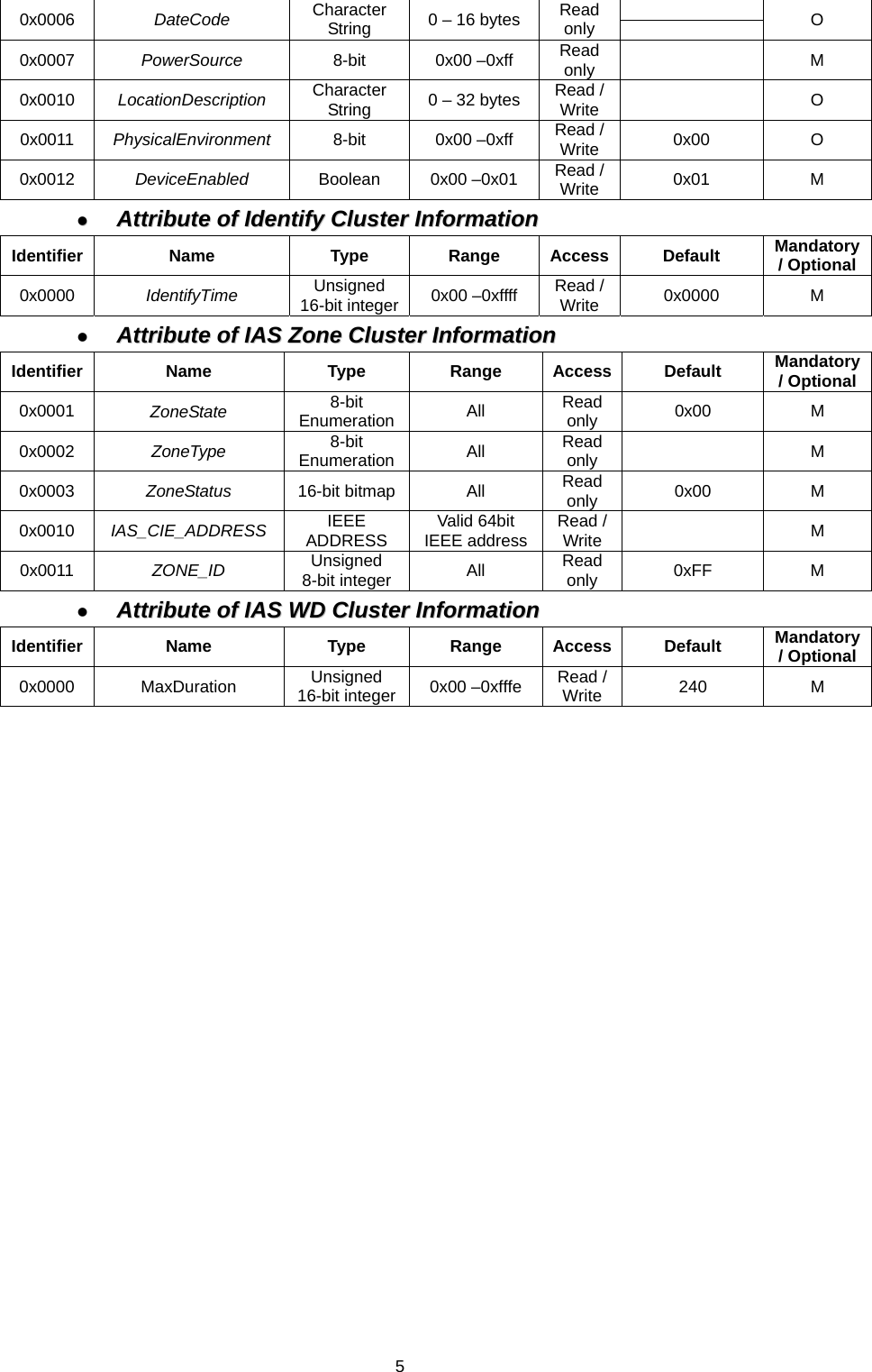
Climax Technology Co Ltd Indoor Siren SR 32ZBS 20160627 FCC
UserManual.wiki
>
Climax Technology Co
>
SRZB User Manual
Users Manual
Navigation menu
Upload a User Manual
Namespaces
Wiki Guide
HTML
PDF
Info
Views
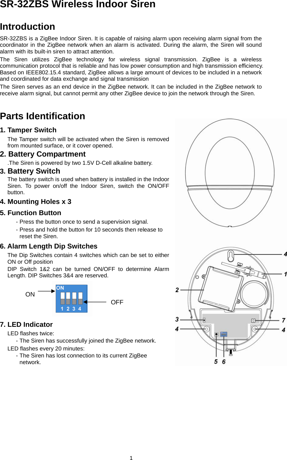
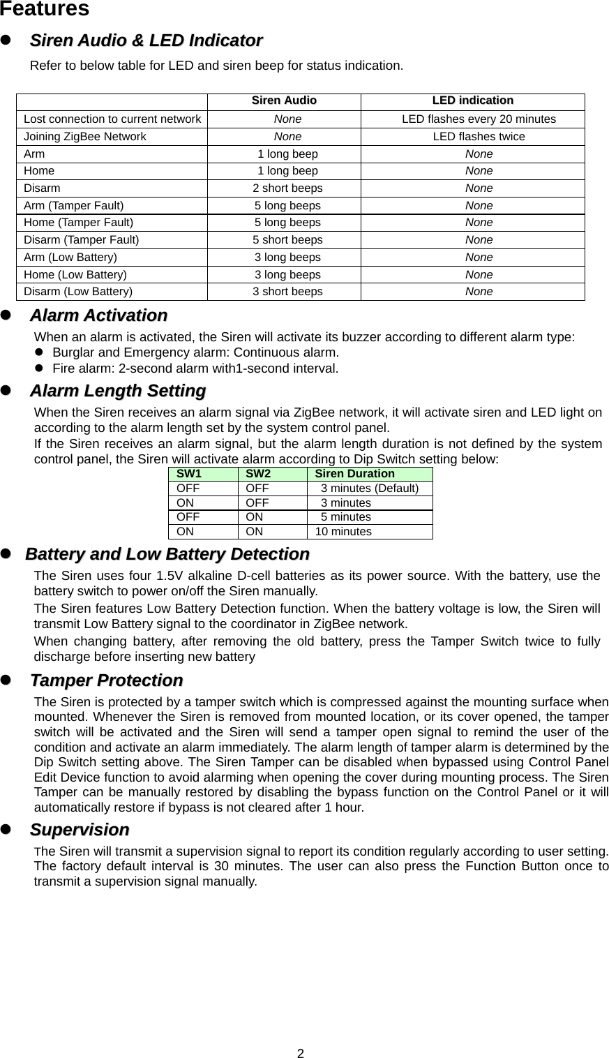
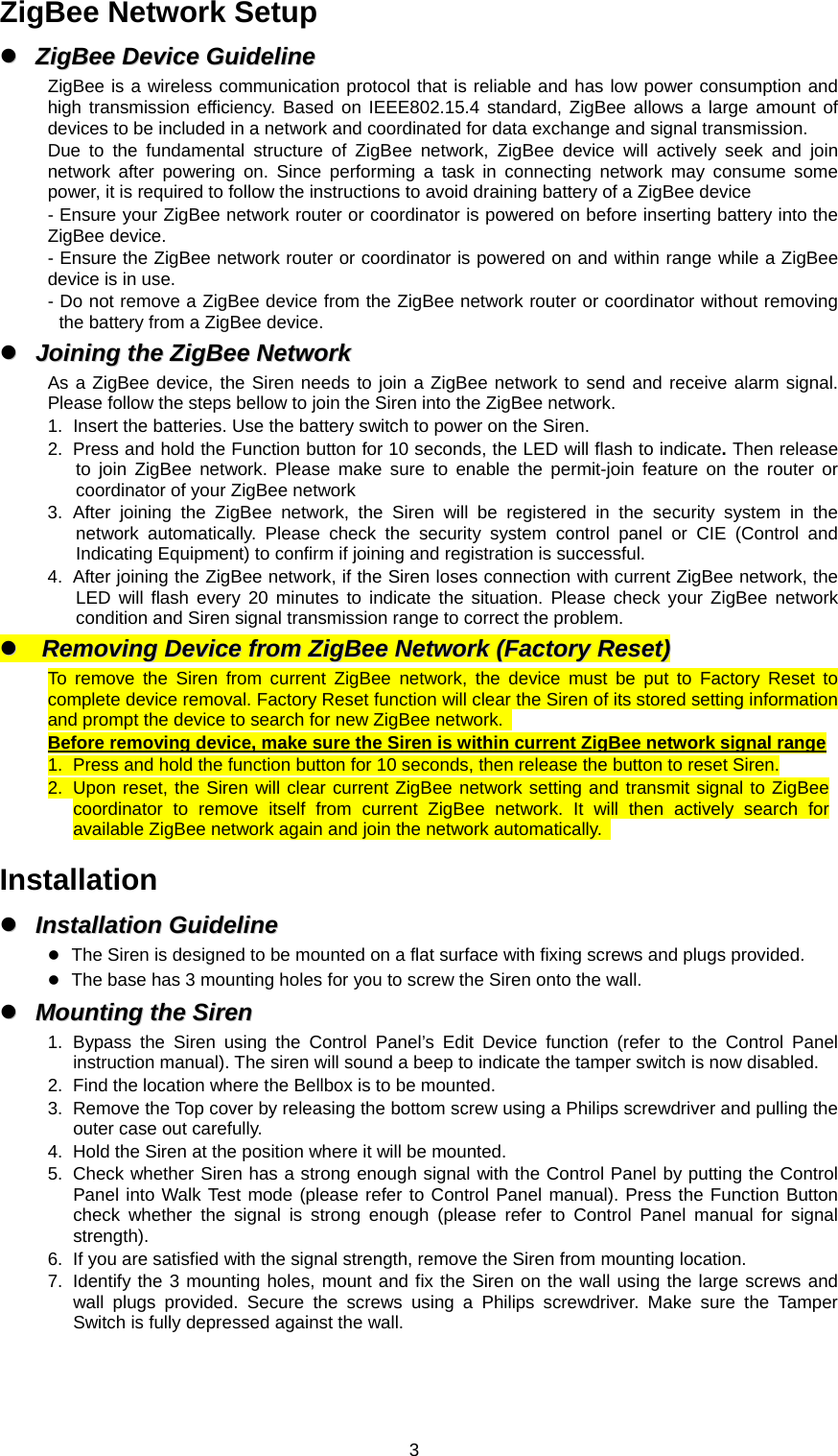
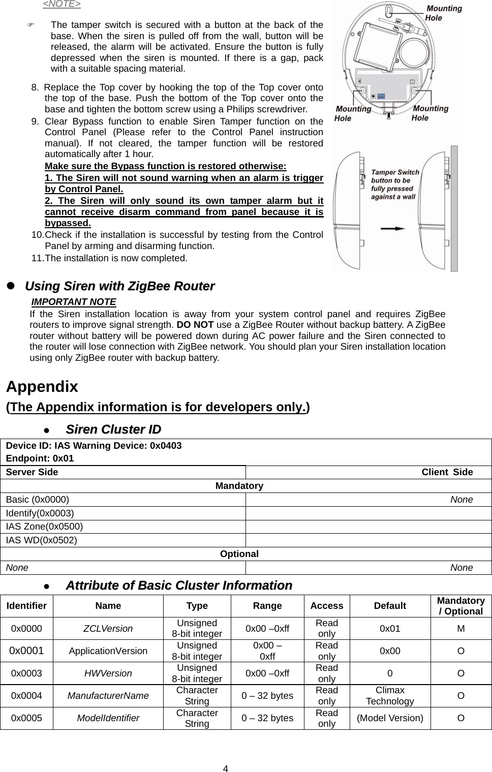
User Manual
Discussion / Help
Navigation