Climax Technology Co SRZB Indoor Siren User Manual SR 32ZBS 20160627 FCC
Climax Technology Co Ltd Indoor Siren SR 32ZBS 20160627 FCC
Users Manual
1
SR-32ZBS Wireless Indoor Siren
Introduction
SR-32ZBS is a ZigBee Indoor Siren. It is capable of raising alarm upon receiving alarm signal from the
coordinator in the ZigBee network when an alarm is activated. During the alarm, the Siren will sound
alarm with its built-in siren to attract attention.
The Siren utilizes ZigBee technology for wireless signal transmission. ZigBee is a wireless
communication protocol that is reliable and has low power consumption and high transmission efficiency.
Based on IEEE802.15.4 standard, ZigBee allows a large amount of devices to be included in a network
and coordinated for data exchange and signal transmission
The Siren serves as an end device in the ZigBee network. It can be included in the ZigBee network to
receive alarm signal, but cannot permit any other ZigBee device to join the network through the Siren.
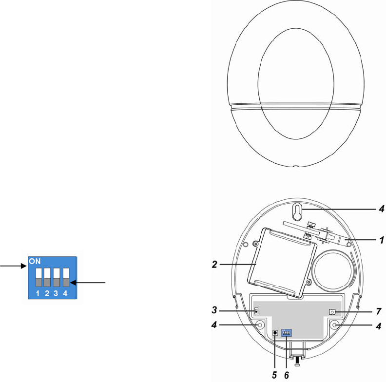
Parts Identification
1. Tamper Switch
The Tamper switch will be activated when the Siren is removed
from mounted surface, or it cover opened.
2. Battery Compartment
.The Siren is powered by two 1.5V D-Cell alkaline battery.
3. Battery Switch
The battery switch is used when battery is installed in the Indoor
Siren. To power on/off the Indoor Siren, switch the ON/OFF
button.
4. Mounting Holes x 3
5. Function Button
- Press the button once to send a supervision signal.
- Press and hold the button for 10 seconds then release to
reset the Siren.
6. Alarm Length Dip Switches
The Dip Switches contain 4 switches which can be set to either
ON or Off position
DIP Switch 1&2 can be turned ON/OFF to determine Alarm
Length. DIP Switches 3&4 are reserved.
7. LED Indicator
LED flashes twice:
- The Siren has successfully joined the ZigBee network.
LED flashes every 20 minutes:
- The Siren has lost connection to its current ZigBee
network.
ON OFF

2
Features
S
Si
ir
re
en
n
A
Au
ud
di
io
o
&
&
L
LE
ED
D
I
In
nd
di
ic
ca
at
to
or
r
Refer to below table for LED and siren beep for status indication.
A
Al
la
ar
rm
m
A
Ac
ct
ti
iv
va
at
ti
io
on
n
When an alarm is activated, the Siren will activate its buzzer according to different alarm type:
Burglar and Emergency alarm: Continuous alarm.
Fire alarm: 2-second alarm with1-second interval.
A
Al
la
ar
rm
m
L
Le
en
ng
gt
th
h
S
Se
et
tt
ti
in
ng
g
When the Siren receives an alarm signal via ZigBee network, it will activate siren and LED light on
according to the alarm length set by the system control panel.
If the Siren receives an alarm signal, but the alarm length duration is not defined by the system
control panel, the Siren will activate alarm according to Dip Switch setting below:
SW1 SW2 Siren Duration
OFF OFF 3 minutes (Default)
ON OFF 3 minutes
OFF ON 5 minutes
ON ON 10 minutes
B
Ba
at
tt
te
er
ry
y
a
an
nd
d
L
Lo
ow
w
B
Ba
at
tt
te
er
ry
y
D
De
et
te
ec
ct
ti
io
on
n
The Siren uses four 1.5V alkaline D-cell batteries as its power source. With the battery, use the
battery switch to power on/off the Siren manually.
The Siren features Low Battery Detection function. When the battery voltage is low, the Siren will
transmit Low Battery signal to the coordinator in ZigBee network.
When changing battery, after removing the old battery, press the Tamper Switch twice to fully
discharge before inserting new battery
T
Ta
am
mp
pe
er
r
P
Pr
ro
ot
te
ec
ct
ti
io
on
n
The Siren is protected by a tamper switch which is compressed against the mounting surface when
mounted. Whenever the Siren is removed from mounted location, or its cover opened, the tamper
switch will be activated and the Siren will send a tamper open signal to remind the user of the
condition and activate an alarm immediately. The alarm length of tamper alarm is determined by the
Dip Switch setting above. The Siren Tamper can be disabled when bypassed using Control Panel
Edit Device function to avoid alarming when opening the cover during mounting process. The Siren
Tamper can be manually restored by disabling the bypass function on the Control Panel or it will
automatically restore if bypass is not cleared after 1 hour.
S
Su
up
pe
er
rv
vi
is
si
io
on
n
The Siren will transmit a supervision signal to report its condition regularly according to user setting.
The factory default interval is 30 minutes. The user can also press the Function Button once to
transmit a supervision signal manually.
S
Si
ir
re
en
n
A
Au
ud
di
io
o
L
LE
ED
D
i
in
nd
di
ic
ca
at
ti
io
on
n
Lost connection to current network None LED flashes every 20 minutes
Joining ZigBee Network None LED flashes twice
Arm 1 long beep None
Home 1 long beep None
Disarm 2 short beeps None
Arm (Tamper Fault) 5 long beeps None
Home (Tamper Fault) 5 long beeps None
Disarm (Tamper Fault) 5 short beeps None
Arm (Low Battery) 3 long beeps None
Home (Low Battery) 3 long beeps None
Disarm (Low Battery) 3 short beeps None

3
ZigBee Network Setup
Z
Zi
ig
gB
Be
ee
e
D
De
ev
vi
ic
ce
e
G
Gu
ui
id
de
el
li
in
ne
e
ZigBee is a wireless communication protocol that is reliable and has low power consumption and
high transmission efficiency. Based on IEEE802.15.4 standard, ZigBee allows a large amount of
devices to be included in a network and coordinated for data exchange and signal transmission.
Due to the fundamental structure of ZigBee network, ZigBee device will actively seek and join
network after powering on. Since performing a task in connecting network may consume some
power, it is required to follow the instructions to avoid draining battery of a ZigBee device
- Ensure your ZigBee network router or coordinator is powered on before inserting battery into the
ZigBee device.
- Ensure the ZigBee network router or coordinator is powered on and within range while a ZigBee
device is in use.
- Do not remove a ZigBee device from the ZigBee network router or coordinator without removing
the battery from a ZigBee device.
J
Jo
oi
in
ni
in
ng
g
t
th
he
e
Z
Zi
ig
gB
Be
ee
e
N
Ne
et
tw
wo
or
rk
k
As a ZigBee device, the Siren needs to join a ZigBee network to send and receive alarm signal.
Please follow the steps bellow to join the Siren into the ZigBee network.
1. Insert the batteries. Use the battery switch to power on the Siren.
2. Press and hold the Function button for 10 seconds, the LED will flash to indicate. Then release
to join ZigBee network. Please make sure to enable the permit-join feature on the router or
coordinator of your ZigBee network
3. After joining the ZigBee network, the Siren will be registered in the security system in the
network automatically. Please check the security system control panel or CIE (Control and
Indicating Equipment) to confirm if joining and registration is successful.
4. After joining the ZigBee network, if the Siren loses connection with current ZigBee network, the
LED will flash every 20 minutes to indicate the situation. Please check your ZigBee network
condition and Siren signal transmission range to correct the problem.
R
Re
em
mo
ov
vi
in
ng
g
D
De
ev
vi
ic
ce
e
f
fr
ro
om
m
Z
Zi
ig
gB
Be
ee
e
N
Ne
et
tw
wo
or
rk
k
(
(F
Fa
ac
ct
to
or
ry
y
R
Re
es
se
et
t)
)
To remove the Siren from current ZigBee network, the device must be put to Factory Reset to
complete device removal. Factory Reset function will clear the Siren of its stored setting information
and prompt the device to search for new ZigBee network.
Before removing device, make sure the Siren is within current ZigBee network signal range
1. Press and hold the function button for 10 seconds, then release the button to reset Siren.
2. Upon reset, the Siren will clear current ZigBee network setting and transmit signal to ZigBee
coordinator to remove itself from current ZigBee network. It will then actively search for
available ZigBee network again and join the network automatically.
Installation
I
In
ns
st
ta
al
ll
la
at
ti
io
on
n
G
Gu
ui
id
de
el
li
in
ne
e
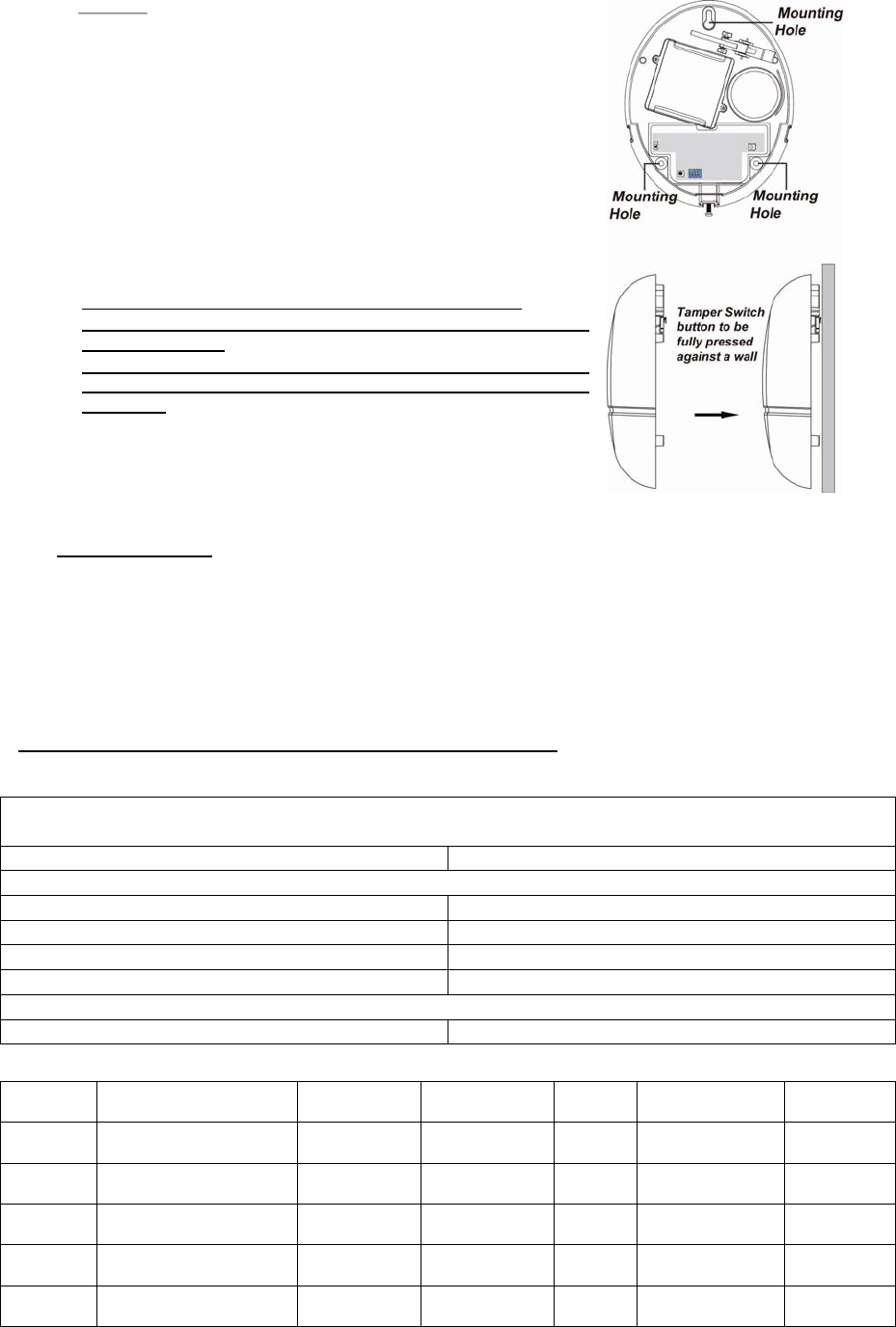
The Siren is designed to be mounted on a flat surface with fixing screws and plugs provided.
The base has 3 mounting holes for you to screw the Siren onto the wall.
M
Mo
ou
un
nt
ti
in
ng
g
t
th
he
e
S
Si
ir
re
en
n
1. Bypass the Siren using the Control Panel’s Edit Device function (refer to the Control Panel
instruction manual). The siren will sound a beep to indicate the tamper switch is now disabled.
2. Find the location where the Bellbox is to be mounted.
3. Remove the Top cover by releasing the bottom screw using a Philips screwdriver and pulling the
outer case out carefully.
4. Hold the Siren at the position where it will be mounted.
5. Check whether Siren has a strong enough signal with the Control Panel by putting the Control
Panel into Walk Test mode (please refer to Control Panel manual). Press the Function Button
check whether the signal is strong enough (please refer to Control Panel manual for signal
strength).
6. If you are satisfied with the signal strength, remove the Siren from mounting location.
7. Identify the 3 mounting holes, mount and fix the Siren on the wall using the large screws and
wall plugs provided. Secure the screws using a Philips screwdriver. Make sure the Tamper
Switch is fully depressed against the wall.
4
<
<N
NO
OT
TE
E>
>
The tamper switch is secured with a button at the back of the
base. When the siren is pulled off from the wall, button will be
released, the alarm will be activated. Ensure the button is fully
depressed when the siren is mounted. If there is a gap, pack
with a suitable spacing material.
8. Replace the Top cover by hooking the top of the Top cover onto
the top of the base. Push the bottom of the Top cover onto the
base and tighten the bottom screw using a Philips screwdriver.
9. Clear Bypass function to enable Siren Tamper function on the
Control Panel (Please refer to the Control Panel instruction
manual). If not cleared, the tamper function will be restored
automatically after 1 hour.
Make sure the Bypass function is restored otherwise:
1. The Siren will not sound warning when an alarm is trigger
by Control Panel.
2. The Siren will only sound its own tamper alarm but it
cannot receive disarm command from panel because it is
bypassed.
10. Check if the installation is successful by testing from the Control
Panel by arming and disarming function.
11. The installation is now completed.
U
Us
si
in
ng
g
S
Si
ir
re
en
n
w
wi
it
th
h
Z
Zi
ig
gB
Be
ee
e
R
Ro
ou
ut
te
er
r
IMPORTANT NOTE
If the Siren installation location is away from your system control panel and requires ZigBee
routers to improve signal strength. DO NOT use a ZigBee Router without backup battery. A ZigBee
router without battery will be powered down during AC power failure and the Siren connected to
the router will lose connection with ZigBee network. You should plan your Siren installation location
using only ZigBee router with backup battery.
Appendix
(The Appendix information is for developers only.)
S
Si
ir
re
en
n
C
Cl
lu
us
st
te
er
r
I
ID
D
Device ID: IAS Warning Device: 0x0403
Endpoint: 0x01
Server Side Client Side
Mandatory
Basic (0x0000) None
Identify(0x0003)
IAS Zone(0x0500)
IAS WD(0x0502)
Optional
None None
A
At
tt
tr
ri
ib
bu
ut
te
e
o
of
f
B
Ba
as
si
ic
c
C
Cl
lu
us
st
te
er
r
I
In
nf
fo
or
rm
ma
at
ti
io
on
n
Identifier Name Type Range Access Default
Mandatory
/ Optional
0x0000 ZCLVersion Unsigned
8-bit integer 0x00 –0xff Read
only 0x01 M
0x0001 ApplicationVersion Unsigned
8-bit integer 0x00 –
0xff Read
only 0x00 O
0x0003 HWVersion Unsigned
8-bit integer 0x00 –0xff Read
only 0 O
0x0004 ManufacturerName Character
String 0 – 32 bytes Read
only Climax
Technology O
0x0005 ModelIdentifier Character
String 0 – 32 bytes Read
only (Model Version) O

5
0x0006 DateCode Character
String 0 – 16 bytes Read
only O
0x0007 PowerSource 8-bit 0x00 –0xff
Read
only M
0x0010 LocationDescription Character
String 0 – 32 bytes Read /
Write O
0x0011 PhysicalEnvironment 8-bit 0x00 –0xff
Read /
Write 0x00 O
0x0012 DeviceEnabled Boolean 0x00 –0x01
Read /
Write 0x01 M
A
At
tt
tr
ri
ib
bu
ut
te
e
o
of
f
I
Id
de
en
nt
ti
if
fy
y
C
Cl
lu
us
st
te
er
r
I
In
nf
fo
or
rm
ma
at
ti
io
on
n
Identifier Name Type Range Access Default
Mandatory
/ Optional
0x0000 IdentifyTime Unsigned
16-bit integer 0x00 –0xffff Read /
Write 0x0000 M
A
At
tt
tr
ri
ib
bu
ut
te
e
o
of
f
I
IA
AS
S
Z
Zo
on
ne
e
C
Cl
lu
us
st
te
er
r
I
In
nf
fo
or
rm
ma
at
ti
io
on
n
Identifier Name Type Range Access Default
Mandatory
/ Optional
0x0001 ZoneState 8-bit
Enumeration All Read
only 0x00 M
0x0002 ZoneType 8-bit
Enumeration All Read
only M
0x0003 ZoneStatus 16-bit bitmap All Read
only 0x00 M
0x0010 IAS_CIE_ADDRESS IEEE
ADDRESS Valid 64bit
IEEE address Read /
Write M
0x0011 ZONE_ID Unsigned
8-bit integer All Read
only 0xFF M
A
At
tt
tr
ri
ib
bu
ut
te
e
o
of
f
I
IA
AS
S
W
WD
D
C
Cl
lu
us
st
te
er
r
I
In
nf
fo
or
rm
ma
at
ti
io
on
n
Identifier Name Type Range Access Default
Mandatory
/ Optional
0x0000 MaxDuration Unsigned
16-bit integer 0x00 –0xfffe Read /
Write 240 M
6
Federal Communication Commission Interference Statement
This equipment has been tested and found to comply with the limits
for a Class B digital device, pursuant to Part 15 of the FCC Rules.
These limits are designed to provide reasonable protection against
harmful interference in a residential installation.
This equipment generates, uses and can radiate radio frequency
energy and, if not installed and used in accordance with the
instructions, may cause harmful interference to radio communications.
However, there is no guarantee that interference will not occur in a
particular installation. If this equipment does cause harmful
interference to radio or television reception, which can be determined
by turning the equipment off and on, the user is encouraged to try to
correct the interference by one of the following measures:
. Reorient or relocate the receiving antenna.
. Increase the separation between the equipment and receiver.
. Connect the equipment into an outlet on a circuit different from that
to which the receiver is connected.
. Consult the dealer or an experienced radio/TV technician for help.
FCC Caution
: To assure continued compliance, any changes or
modifications not expressly approved by the party responsible for
compliance could void the user's authority to operate this equipment.
(Example - use only shielded interface cables when connecting to
computer or peripheral devices).
FCC Radiation Exposure Statement
This equipment complies with FCC RF radiation exposure limits set
forth for an uncontrolled environment. This equipment should be
installed and operated with a minimum distance of 20 centimeters
between the radiator and your body.
This transmitter must not be co-located or operating in conjunction
with any other antenna or transmitter.
The antennas used for this transmitter must be installed to provide a
separation distance of at least 20 cm from all persons and must not
be co-located or operating in conjunction with any other antenna or
transmitter.
This device complies with Part 15 of the FCC Rules. Operation is
subject to the following two conditions:
(1) This device may not cause harmful interference, and
(2) This device must accept any interference received, including
interference that may cause undesired operation.