Climax Technology Co TS9 Temperature Sensor User Manual TS 9EL 20171125
Climax Technology Co Ltd Temperature Sensor TS 9EL 20171125
UserManual.wiki
>
Climax Technology Co
>
TS9 User Manual
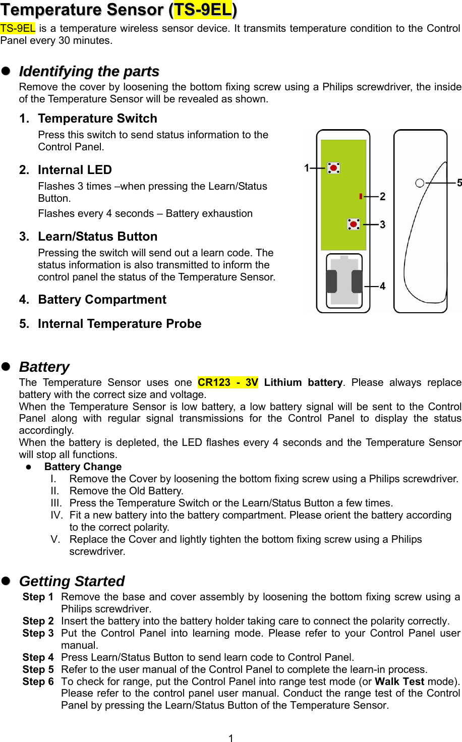
Users Manual
Navigation menu
Upload a User Manual
Namespaces
Wiki Guide
HTML
PDF
Info
Views
User Manual
Discussion / Help
Navigation