Climax Technology Co TS9 Temperature Sensor User Manual TS 9EL 20171125
Climax Technology Co Ltd Temperature Sensor TS 9EL 20171125
Users Manual
1
T
Te
em
mp
pe
er
ra
at
tu
ur
re
e
S
Se
en
ns
so
or
r
(
(T
TS
S-
-9
9E
EL
L)
)
TS-9EL is a temperature wireless sensor device. It transmits temperature condition to the Control
Panel every 30 minutes.
I
Id
de
en
nt
ti
if
fy
yi
in
ng
g
t
th
he
e
p
pa
ar
rt
ts
s
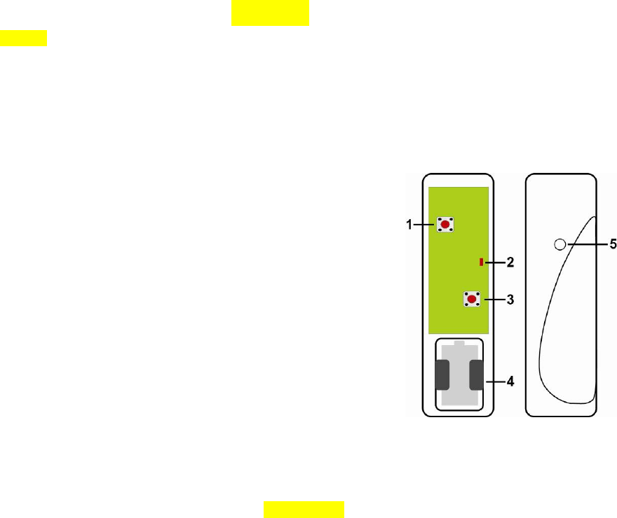
Remove the cover by loosening the bottom fixing screw using a Philips screwdriver, the inside
of the Temperature Sensor will be revealed as shown.
1. Temperature Switch
Press this switch to send status information to the
Control Panel.
2. Internal LED
Flashes 3 times –when pressing the Learn/Status
Button.
Flashes every 4 seconds – Battery exhaustion
3. Learn/Status Button
Pressing the switch will send out a learn code. The
status information is also transmitted to inform the
control panel the status of the Temperature Sensor.
4. Battery Compartment
5. Internal Temperature Probe
Battery
The Temperature Sensor uses one CR123 - 3V Lithium battery. Please always replace
battery with the correct size and voltage.
When the Temperature Sensor is low battery, a low battery signal will be sent to the Control
Panel along with regular signal transmissions for the Control Panel to display the status
accordingly.
When the battery is depleted, the LED flashes every 4 seconds and the Temperature Sensor
will stop all functions.
Battery Change
I. Remove the Cover by loosening the bottom fixing screw using a Philips screwdriver.
II. Remove the Old Battery.
III. Press the Temperature Switch or the Learn/Status Button a few times.
IV. Fit a new battery into the battery compartment. Please orient the battery according
to the correct polarity.
V. Replace the Cover and lightly tighten the bottom fixing screw using a Philips
screwdriver.
Getting Started
Step 1 Remove the base and cover assembly by loosening the bottom fixing screw using a
Philips screwdriver.
Step 2 Insert the battery into the battery holder taking care to connect the polarity correctly.
Step 3 Put the Control Panel into learning mode. Please refer to your Control Panel user
manual.
Step 4 Press Learn/Status Button to send learn code to Control Panel.
Step 5 Refer to the user manual of the Control Panel to complete the learn-in process.
Step 6 To check for range, put the Control Panel into range test mode (or Walk Test mode).
Please refer to the control panel user manual. Conduct the range test of the Control
Panel by pressing the Learn/Status Button of the Temperature Sensor.

2
Step 7 When you are satisfied with the Temperature Sensor signal range at the chosen
location, proceed to mounting.
Mounting Methods
There are two ways to mount the Temperature Sensor, by either Self-adhesive installation or
Screw mounting.
Self adhesive mounting
I. Clean the surface with a suitable degreaser.
II. Remove the protective covering from one side of the double-sided adhesive pad and
firmly apply to the back of the device.
III. Next remove the other cover and firmly press the item onto the desired location.
<
<N
NO
OT
TE
E>
>
Do not use the adhesive pad method of installation on a surface with peeling or
cracked paint, or on a rough surface.
Screw mounting
The Base has two knockouts, where the plastic is thinner, for mounting purpose.
To mount the Temperature Sensor
I. Remove the Cover by loosening the bottom fixing screw using a Philips screwdriver.
II. Break through the knockouts on the base
III. Using the holes as a template, drill holes in the surface
IV. Insert the wall plugs if fixing into plaster or brick
V. Screw the base into the wall plugs
VI. Replace the Cover and lightly tighten the bottom fixing screw using a Philips
screwdriver.
Operation
The temperature detection range is -10℃-50℃.
The Temperature Sensor will transmit a temperature signal periodically at intervals of
~30 minutes along with supervision signal.
This device complies with Part 15 of the FCC Rules. Operation is subject to the following two
conditions:
(1) This device may not cause harmful interference, and
(2) This device must accept any interference received, including interference that may cause
undesired operation.
FCC Caution:
To assure continued compliance, any changes or modifications not expressly approved by the party
responsible for compliance may void the user's authority to operate this equipment.
(Example - use only shielded interface cables when connecting to computer or peripheral devices).