Climax Technology Co VCM Valve Control Machine User Manual VCM 20060807
Climax Technology Co Ltd Valve Control Machine VCM 20060807
UserManual.wiki
>
Climax Technology Co
>
VCM User Manual
Users Manual
Navigation menu
Upload a User Manual
Namespaces
Wiki Guide
HTML
PDF
Info
Views
User Manual
Discussion / Help
Navigation
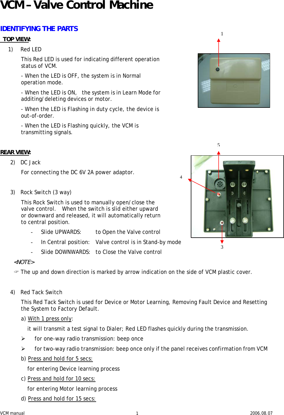
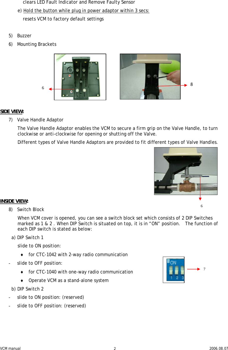
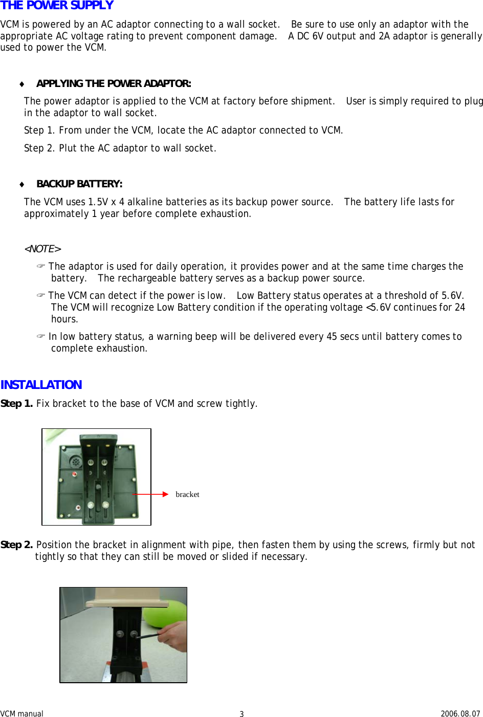
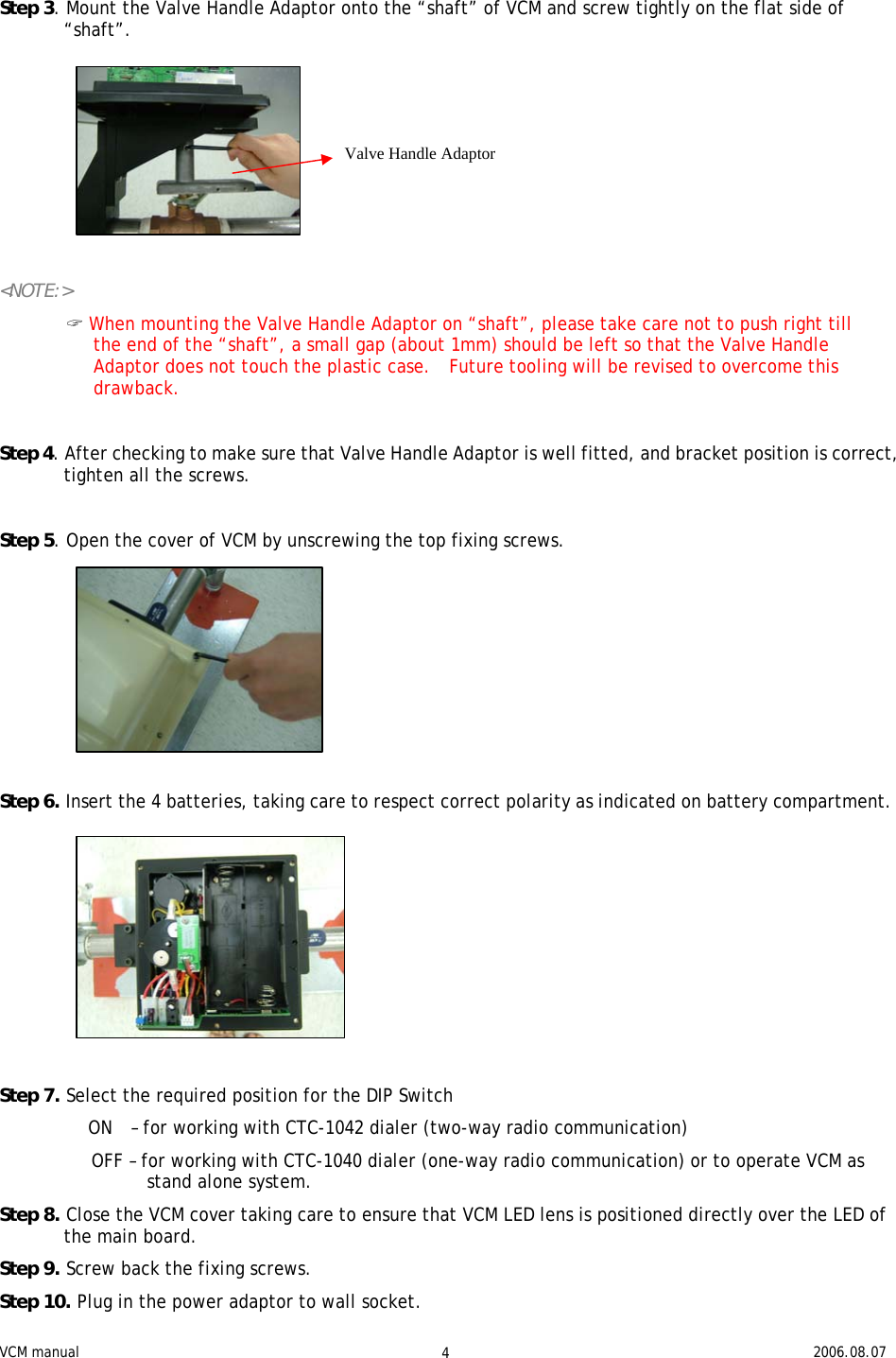
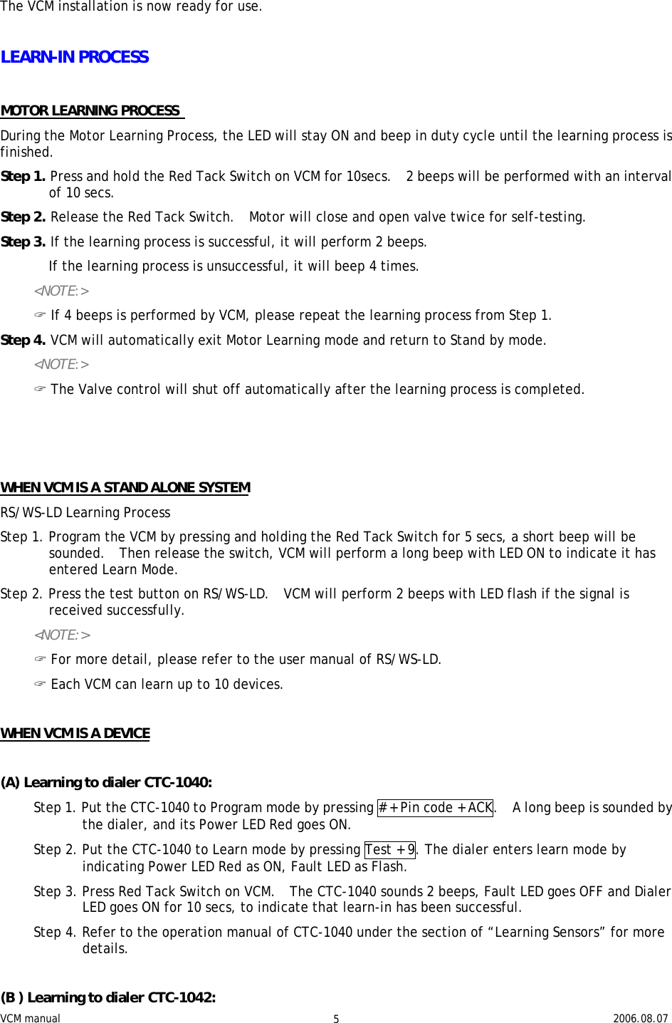
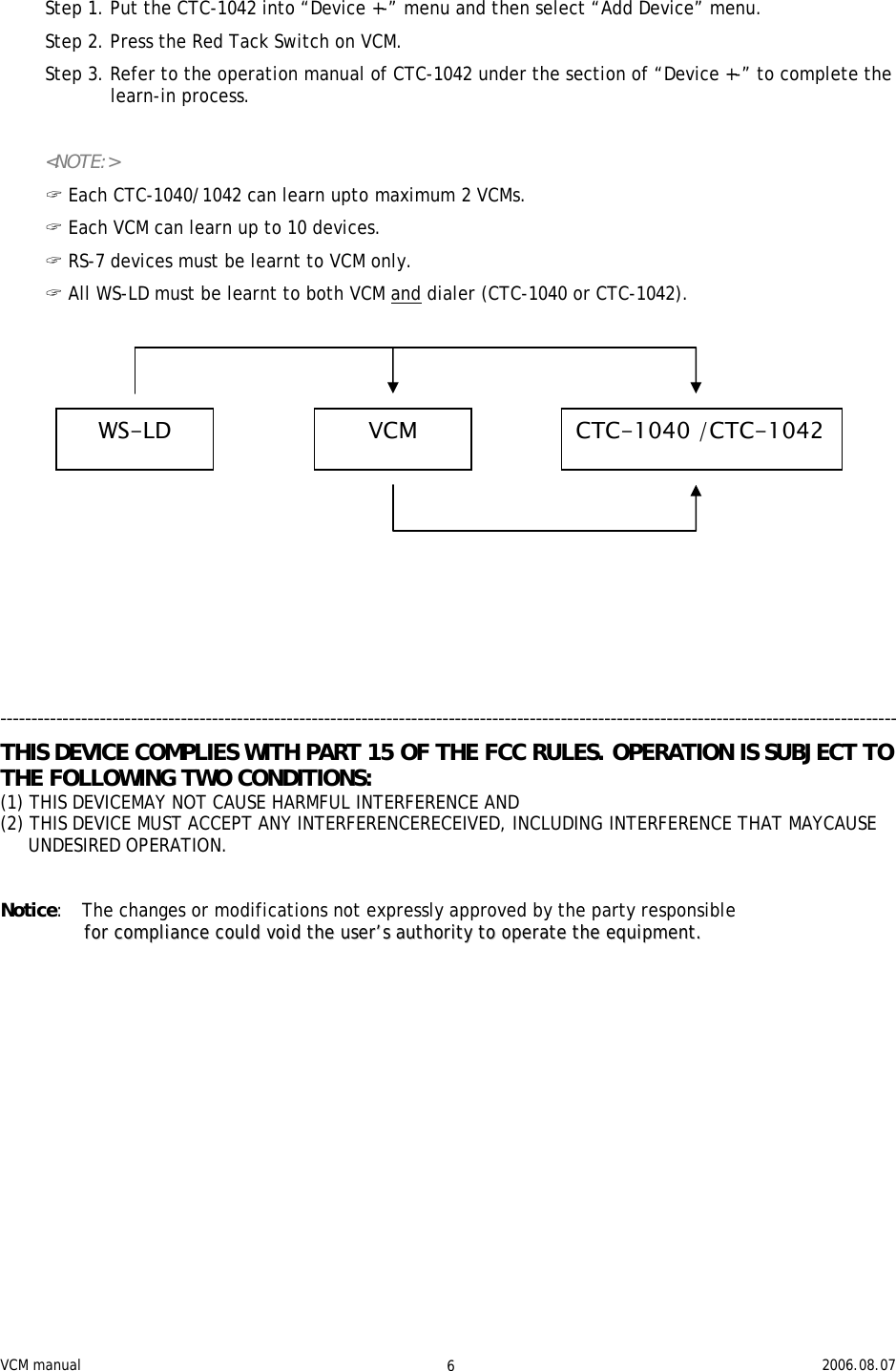
![VCM manual 2006.08.07 7 SUPERVISORY SIGNAL ♦ DEVICE (WS-LD) SUPERVISION SIGNAL: In normal condition, VCM will receive supervisory signal from WS-LD at intervals of 4 hrs randomly. If this supervision signal is not received for 12 hrs, VCM will report as “out of order” and LED on VCM will flash in duty cycle to indicate device is out-of-order. ♦ If the device is out-of-order, LED will flash and 2 long beeps will sound at intervals of 45 sec. ♦ VCM SUPERVISION SIGNAL: After installation, the VCM will automatically transmit Supervisory signals periodically to the CTC-1042 / CTC-1040 at intervals of 24~39 hrs randomly. SELF-CHECKING The VCM will check the motor every 45 days by performing a self-test. The self-test comprises of one cycle [valve-shut] + [valve-open] action. <NOTE:> (( TThhiiss sseellff--cchheecckk wwiillll bbee ddoonnee oonnllyy iiff vvaallvvee iiss iinn ooppeenn ccoonnddiittiioonn.. (( IIff tthhee sseellff--cchheecckk iiss ssuucccceessssffuull,, VVCCMM wwiillll ssoouunndd 22 WS-LD / RS 1~10 VCM 2VCM 1WS-LD / RS 1~10 CTC-1040 or CTC-1042 Other sensors SD / WS-LD / CO / GAS / PB/ WTR… 1~8 Total max. 30 devices](https://usermanual.wiki/Climax-Technology-Co/VCM/User-Guide-693023-Page-7.png)