Climax Technology Co VCM Valve Control Machine User Manual VCM 20060807
Climax Technology Co Ltd Valve Control Machine VCM 20060807
Users Manual
VCM manual 2006.08.07
1
VCM – Valve Control Machine
IDENTIFYING THE PARTS
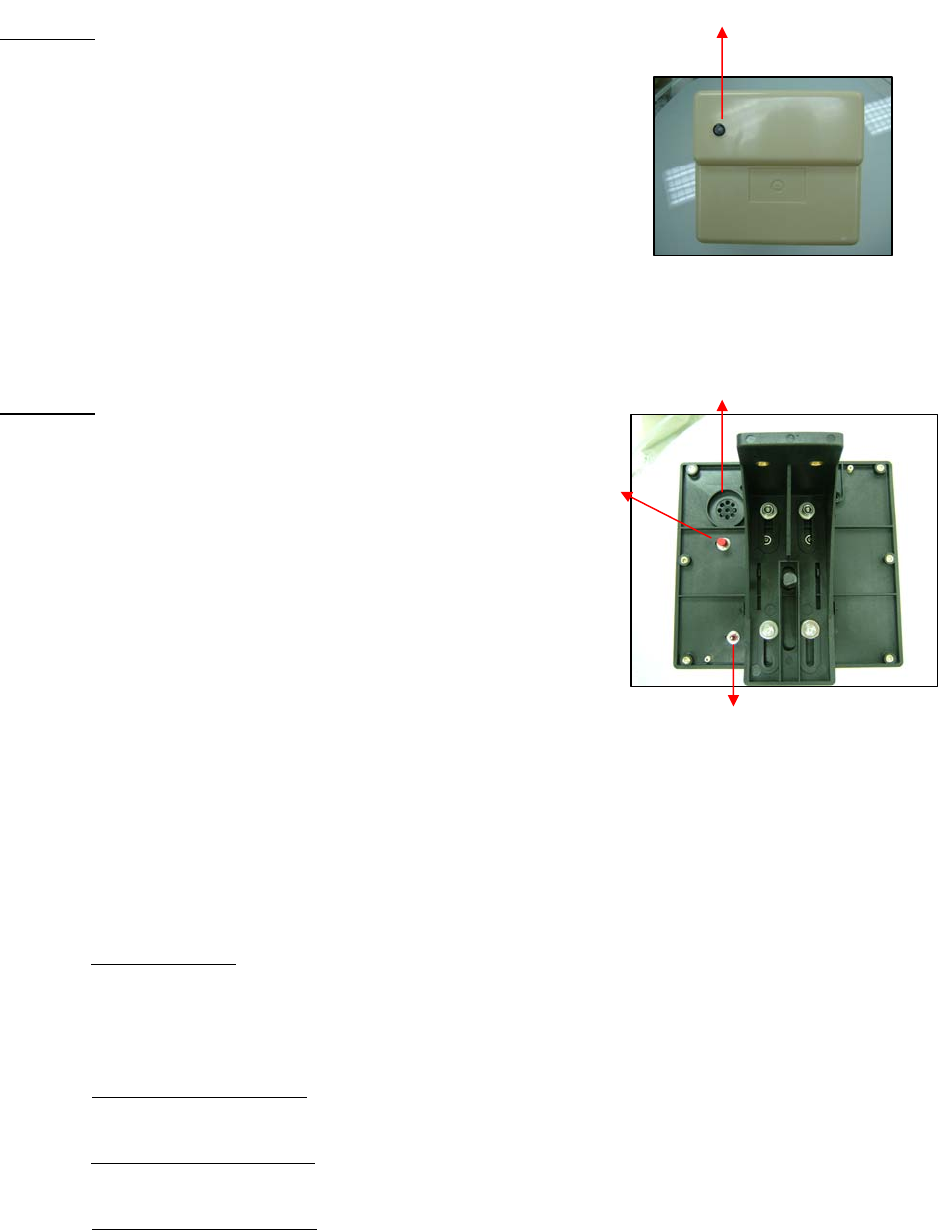
TOP VIEW:
1) Red LED
This Red LED is used for indicating different operation
status of VCM.
- When the LED is OFF, the system is in Normal
operation mode.
- When the LED is ON, the system is in Learn Mode for
additing/deleting devices or motor.
- When the LED is Flashing in duty cycle, the device is
out-of-order.
- When the LED is Flashing quickly, the VCM is
transmitting signals.
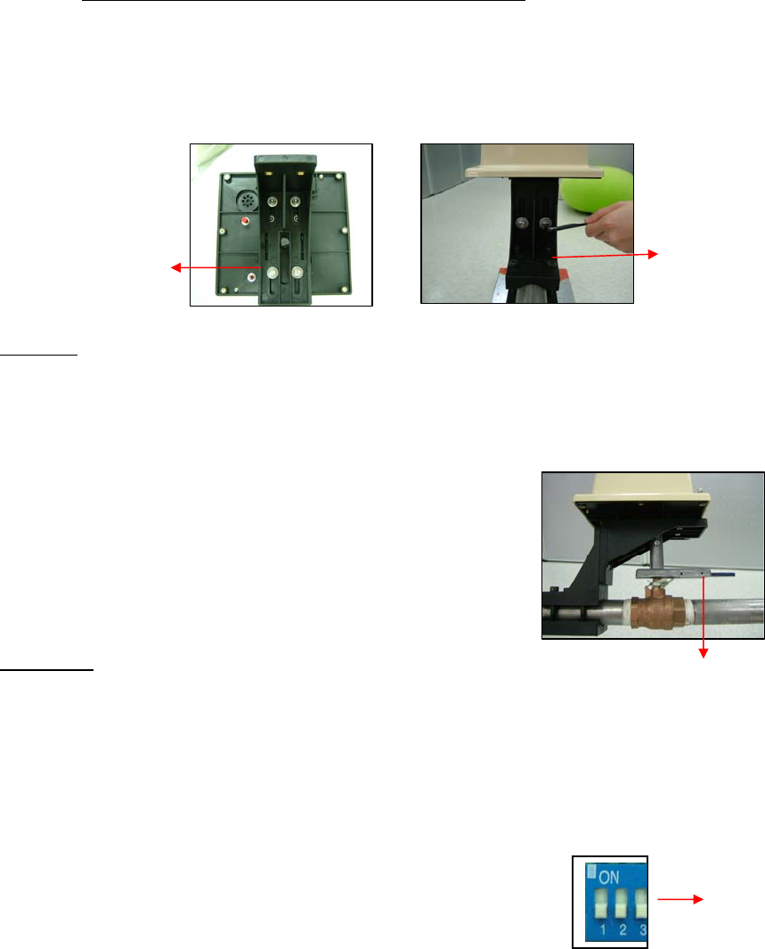
REAR VIEW:
2) DC Jack
For connecting the DC 6V 2A power adaptor.
3) Rock Switch (3 way)
This Rock Switch is used to manually open/close the
valve control. When the switch is slid either upward
or downward and released, it will automatically return
to central position.
- Slide UPWARDS: to Open the Valve control
- In Central position: Valve control is in Stand-by mode
- Slide DOWNWARDS: to Close the Valve control
<NOTE>
" The up and down direction is marked by arrow indication on the side of VCM plastic cover.
4) Red Tack Switch
This Red Tack Switch is used for Device or Motor Learning, Removing Fault Device and Resetting
the System to Factory Default.
a) With 1 press only:
it will transmit a test signal to Dialer; Red LED flashes quickly during the transmission.
¾ for one-way radio transmission: beep once
¾ for two-way radio transmission: beep once only if the panel receives confirmation from VCM
b) Press and hold for 5 secs:
for entering Device learning process
c) Press and hold for 10 secs:
for entering Motor learning process
d) Press and hold for 15 secs:
1
3
4
5
VCM manual 2006.08.07
2
clears LED Fault Indicator and Remove Faulty Sensor
e) Hold the button while plug in power adaptor within 3 secs:
resets VCM to factory default settings
5) Buzzer
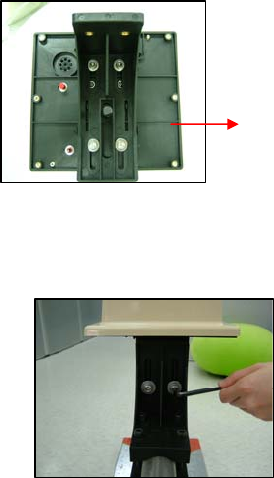
6) Mounting Brackets
SIDE VIEW:
7) Valve Handle Adaptor
The Valve Handle Adaptor enables the VCM to secure a firm grip on the Valve Handle, to turn
clockwise or anti-clockwise for opening or shutting off the Valve.
Different types of Valve Handle Adaptors are provided to fit different types of Valve Handles.
INSIDE VIEW:
8) Switch Block
When VCM cover is opened, you can see a switch block set which consists of 2 DIP Switches
marked as 1 & 2 . When DIP Switch is situated on top, it is in “ON” position. The function of
each DIP switch is stated as below:
a) DIP Switch 1
slide to ON position:
♦ for CTC-1042 with 2-way radio communication
- slide to OFF position:
♦ for CTC-1040 with one-way radio communication
♦ Operate VCM as a stand-alone system
b) DIP Switch 2
- slide to ON position: (reserved)
- slide to OFF position: (reserved)
8
6
6
7
VCM manual 2006.08.07
3
THE POWER SUPPLY
VCM is powered by an AC adaptor connecting to a wall socket. Be sure to use only an adaptor with the
appropriate AC voltage rating to prevent component damage. A DC 6V output and 2A adaptor is generally
used to power the VCM.
♦ APPLYING THE POWER ADAPTOR:
The power adaptor is applied to the VCM at factory before shipment. User is simply required to plug
in the adaptor to wall socket.
Step 1. From under the VCM, locate the AC adaptor connected to VCM.
Step 2. Plut the AC adaptor to wall socket.
♦ BACKUP BATTERY:
The VCM uses 1.5V x 4 alkaline batteries as its backup power source. The battery life lasts for
approximately 1 year before complete exhaustion.
<NOTE>
" The adaptor is used for daily operation, it provides power and at the same time charges the
battery. The rechargeable battery serves as a backup power source.
" The VCM can detect if the power is low. Low Battery status operates at a threshold of 5.6V.
The VCM will recognize Low Battery condition if the operating voltage <5.6V continues for 24
hours.
" In low battery status, a warning beep will be delivered every 45 secs until battery comes to
complete exhaustion.
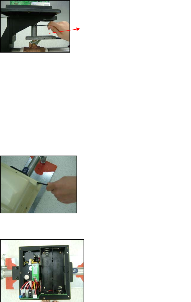
INSTALLATION
Step 1. Fix bracket to the base of VCM and screw tightly.
Step 2. Position the bracket in alignment with pipe, then fasten them by using the screws, firmly but not
tightly so that they can still be moved or slided if necessary.
b
racket
VCM manual 2006.08.07
4
Step 3. Mount the Valve Handle Adaptor onto the “shaft” of VCM and screw tightly on the flat side of
“shaft”.
<NOTE:>
" When mounting the Valve Handle Adaptor on “shaft”, please take care not to push right till
the end of the “shaft”, a small gap (about 1mm) should be left so that the Valve Handle
Adaptor does not touch the plastic case. Future tooling will be revised to overcome this
drawback.
Step 4. After checking to make sure that Valve Handle Adaptor is well fitted, and bracket position is correct,
tighten all the screws.
Step 5. Open the cover of VCM by unscrewing the top fixing screws.
Step 6. Insert the 4 batteries, taking care to respect correct polarity as indicated on battery compartment.
Step 7. Select the required position for the DIP Switch
ON – for working with CTC-1042 dialer (two-way radio communication)
OFF – for working with CTC-1040 dialer (one-way radio communication) or to operate VCM as
stand alone system.
Step 8. Close the VCM cover taking care to ensure that VCM LED lens is positioned directly over the LED of
the main board.
Step 9. Screw back the fixing screws.
Step 10. Plug in the power adaptor to wall socket.
Valve Handle Adaptor

VCM manual 2006.08.07
5
The VCM installation is now ready for use.
LEARN-IN PROCESS
MOTOR LEARNING PROCESS
During the Motor Learning Process, the LED will stay ON and beep in duty cycle until the learning process is
finished.
Step 1. Press and hold the Red Tack Switch on VCM for 10secs. 2 beeps will be performed with an interval
of 10 secs.
Step 2. Release the Red Tack Switch. Motor will close and open valve twice for self-testing.
Step 3. If the learning process is successful, it will perform 2 beeps.
If the learning process is unsuccessful, it will beep 4 times.
<NOTE:>
" If 4 beeps is performed by VCM, please repeat the learning process from Step 1.
Step 4. VCM will automatically exit Motor Learning mode and return to Stand by mode.
<NOTE:>
" The Valve control will shut off automatically after the learning process is completed.
WHEN VCM IS A STAND ALONE SYSTEM
RS/WS-LD Learning Process
Step 1. Program the VCM by pressing and holding the Red Tack Switch for 5 secs, a short beep will be
sounded. Then release the switch, VCM will perform a long beep with LED ON to indicate it has
entered Learn Mode.
Step 2. Press the test button on RS/WS-LD. VCM will perform 2 beeps with LED flash if the signal is
received successfully.
<NOTE:>
" For more detail, please refer to the user manual of RS/WS-LD.
" Each VCM can learn up to 10 devices.
WHEN VCM IS A DEVICE
(A) Learning to dialer CTC-1040:
Step 1. Put the CTC-1040 to Program mode by pressing # + Pin code + ACK. A long beep is sounded by
the dialer, and its Power LED Red goes ON.
Step 2. Put the CTC-1040 to Learn mode by pressing Test + 9. The dialer enters learn mode by
indicating Power LED Red as ON, Fault LED as Flash.
Step 3. Press Red Tack Switch on VCM. The CTC-1040 sounds 2 beeps, Fault LED goes OFF and Dialer
LED goes ON for 10 secs, to indicate that learn-in has been successful.
Step 4. Refer to the operation manual of CTC-1040 under the section of “Learning Sensors” for more
details.
(B ) Learning to dialer CTC-1042:
VCM manual 2006.08.07
6
Step 1. Put the CTC-1042 into “Device +-” menu and then select “Add Device” menu.
Step 2. Press the Red Tack Switch on VCM.
Step 3. Refer to the operation manual of CTC-1042 under the section of “Device +-” to complete the
learn-in process.
<NOTE:>
" Each CTC-1040/1042 can learn upto maximum 2 VCMs.
" Each VCM can learn up to 10 devices.
" RS-7 devices must be learnt to VCM only.
" All WS-LD must be learnt to both VCM and dialer (CTC-1040 or CTC-1042).
------------------------------------------------------------------------------------------------------------------------------------------------
THIS DEVICE COMPLIES WITH PART 15 OF THE FCC RULES. OPERATION IS SUBJECT TO
THE FOLLOWING TWO CONDITIONS:
(1) THIS DEVICEMAY NOT CAUSE HARMFUL INTERFERENCE AND
(2) THIS DEVICE MUST ACCEPT ANY INTERFERENCERECEIVED, INCLUDING INTERFERENCE THAT MAYCAUSE
UNDESIRED OPERATION.
Notice: The changes or modifications not expressly approved by the party responsible
f
fo
or
r
c
co
om
mp
pl
li
ia
an
nc
ce
e
c
co
ou
ul
ld
d
v
vo
oi
id
d
t
th
he
e
u
us
se
er
r’
’s
s
a
au
ut
th
ho
or
ri
it
ty
y
t
to
o
o
op
pe
er
ra
at
te
e
t
th
he
e
e
eq
qu
ui
ip
pm
me
en
nt
t.
.
WS-LD CTC-1040 /CTC-1042VCM
VCM manual 2006.08.07
7
SUPERVISORY SIGNAL
♦ DEVICE (WS-LD) SUPERVISION SIGNAL:
In normal condition, VCM will receive supervisory signal from WS-LD at intervals of 4 hrs randomly.
If this supervision signal is not received for 12 hrs, VCM will report as “out of order” and LED on VCM
will flash in duty cycle to indicate device is out-of-order.
♦ If the device is out-of-order, LED will flash and 2 long beeps will sound at intervals of 45 sec.
♦ VCM SUPERVISION SIGNAL:
After installation, the VCM will automatically transmit Supervisory signals periodically to the CTC-1042
/ CTC-1040 at intervals of 24~39 hrs randomly.
SELF-CHECKING
The VCM will check the motor every 45 days by performing a self-test. The self-test comprises of one cycle
[valve-shut] + [valve-open] action.
<NOTE:>
(
(
T
Th
hi
is
s
s
se
el
lf
f-
-c
ch
he
ec
ck
k
w
wi
il
ll
l
b
be
e
d
do
on
ne
e
o
on
nl
ly
y
i
if
f
v
va
al
lv
ve
e
i
is
s
i
in
n
o
op
pe
en
n
c
co
on
nd
di
it
ti
io
on
n.
.
(
(
I
If
f
t
th
he
e
s
se
el
lf
f-
-c
ch
he
ec
ck
k
i
is
s
s
su
uc
cc
ce
es
ss
sf
fu
ul
l,
,
V
VC
CM
M
w
wi
il
ll
l
s
so
ou
un
nd
d
2
2
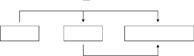
WS-LD / RS
1~10
VCM 2
VCM 1
WS-LD / RS
1~10
CTC-1040
or
CTC-1042
Other sensors
SD / WS-LD / CO / GAS / PB/ WTR…
1~8
Total
max.
30
devices
VCM manual 2006.08.07
8
b
be
ee
ep
ps
s.
.
I
If
f
u
un
ns
su
uc
cc
ce
es
ss
sf
fu
ul
l,
,
V
VC
CM
M
s
so
ou
un
nd
ds
s
4
4
b
be
ee
ep
ps
s.
.
(
(
W
Wh
he
et
th
he
er
r
t
th
he
e
s
se
el
lf
f-
-c
ch
he
ec
ck
k
i
is
s
s
su
uc
cc
ce
es
ss
sf
fu
ul
l
o
or
r
n
no
ot
t,
,
V
VC
CM
M
w
wi
il
ll
l
r
re
ep
po
or
rt
t
i
it
t
t
to
o
C
CT
TC
C-
-1
10
04
40
0
o
or
r
C
CT
TC
C-
-1
10
04
42
2.
.
R
RF
F
S
SI
IG
GN
NA
AL
L
a
a)
)
O
On
ne
e
w
wa
ay
y:
:
(
(f
fo
or
r
C
CT
TC
C-
-1
10
04
40
0)
)
A
An
n
a
an
nt
ti
i-
-c
cl
la
as
sh
h
t
tr
ra
an
ns
sm
mi
is
ss
si
io
on
n
s
se
eq
qu
ue
en
nc
ce
e
c
co
on
ns
si
is
st
ts
s
o
of
f
t
tw
wo
o
p
pa
ac
ck
ke
et
ts
s
s
se
ep
pa
ar
ra
at
te
ed
d
b
by
y
a
a
v
va
ar
ri
ia
ab
bl
le
e
t
ti
im
me
e
d
de
el
la
ay
y.
.
T
Th
he
e
t
ti
im
me
e
d
de
el
la
ay
y
i
is
s
d
de
es
si
ig
gn
ne
ed
d
t
to
o
p
pr
re
ev
ve
en
nt
t
c
cl
la
as
sh
h
w
wh
he
en
n
m
mo
or
re
e
t
th
ha
an
n
o
on
ne
e
t
tr
ra
an
ns
sm
mi
it
tt
te
er
r
d
de
ev
vi
ic
ce
e
i
is
s
t
tr
ra
an
ns
sm
mi
it
tt
ti
in
ng
g
a
at
t
t
th
he
e
s
sa
am
me
e
t
ti
im
me
e.
.

VCM manual 2006.08.07
9
T
Th
he
e
v
va
ar
ri
ia
ab
bl
le
e
t
ti
im
me
e
i
is
s
5
5~
~8
8
s
se
ec
co
on
nd
ds
s.
.
b
b)
)
T
Tw
wo
o
w
wa
ay
y:
:
(
(f
fo
or
r
C
CT
TC
C-
-1
10
04
42
2)
)
E
Ea
ac
ch
h
t
tr
ra
an
ns
sm
mi
is
ss
si
io
on
n
w
wi
il
ll
l
w
wa
ai
it
t
f
fo
or
r
i
it
ts
s
c
co
on
nf
fi
ir
rm
ma
at
ti
io
on
n
s
si
ig
gn
na
al
l.
.
T
Th
he
e
s
sy
ys
st
te
em
m
w
wi
il
ll
l
r
re
et
tr
ry
y
u
up
p
t
to
o
8
8
t
ti
im
me
es
s.
.
c
c)
)
I
In
n
L
Le
ea
ar
rn
n
m
mo
od
de
e:
:
B
Bo
ot
th
h
C
CT
TC
C-
-1
10
04
40
0
a
an
nd
d
C
CT
TC
C-
-1
10
04
42
2
a
ar
re
e
o
on
ne
e-
-w
wa
ay
y
r
ra
ad
di
io
o
c
co
om
mm
mu
un
ni
ic
ca
at
ti
io
on
n
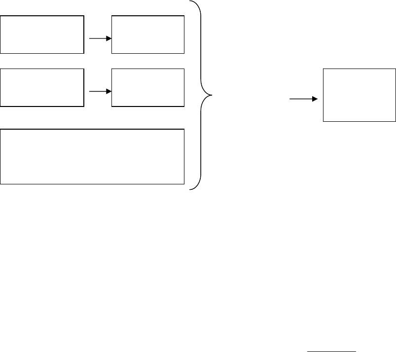
d) In Normal mode:
CTC-1040 is one way radio communication
CTC-1042 is two way radio communication
e) When VCM receives signals from its devices (WS-LD/RS), it will then transmit this signal to the Panel
(including VCM’s own signal). However, during an Emergency, the Valve Open/Close function will be
activated first. Then, it will transmit its signal to the Panel (including VCM’s own signal).
f) Device (WS/GAS/RS) activation:
Controls the valve by its signals.
g) Device (WS/GAS) supervision signal:
Supervision time for 12 hours.
If the device is out-of-order, the LED will flash and 2 long beeps will sound at the interval of 45 sec.. Press
Test button to clear the status nd reset the supervision timer.
h) If Valve Fails to Close:
It will alarm 3 minutes; after 3 minutes, 3 beeps will sound at the interval of 3 hours.
Press Test button to stop the beep.
i) From Panel: (CTC-1042)
VCM manual 2006.08.07
10
TRIGGER
ON/OFF
ROCK SWITCH
ON/OFF
VALVE CLOSE
1) Open/Close Valve control
2) Delete device in VCM
3) Receive device data in VCM
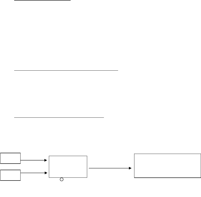
OPERATION
♦ WHEN WS-LD IS TRIGGERED:
When WS-LD is triggered, it will sound an alarm and trigger VCM to shut-off the valve automatically
and send report signal to the dialer.
<NOTE:>
" If VCM fails to shut-off the valve successfully, VCM will sound alarm for 3 mins. During these 3
mins, if Red Tack Switch on VCM is pressed, the alarm can be stopped immediately.
" Whether the Valve shut-off is a success or failure, VCM will report the condition to dialer.
" When WS-LD condition is cleared, the valve will remain shut until it is opened again, either
remotely (by RS) or manually (by VCM’s Rock Switch).
♦ USING RS TO OPEN/SHUT THE VALVE (REMOTELY):
When RS ‘ON’ switch is pressed, VCM will open the valve.
When RS ‘OFF’ switch is pressed, VCM will shut off the valve.
<NOTE:>
" Whether the Valve open or shut-off is a success or failure, VCM will report the condition to dialer.
♦ OPEN/SHUT OF VALVE BY VCM (MANUALLY):
The Valve will be opened by sliding the VCM’s Rock Switch upwards.
The Valve will be shut by sliding the VCM’s Rock Switch downwards.
<NOTE:>
" Whether the Valve open or shut-off is a success or failure, VCM will report the condition to dialer.
REMOVING FAULT DEVICES
Step 1. Press and hold the Red Tack Switch for 15 secs.
Step 2. VCM sounds a melody tone “do-di”
Step 3. VCM will be cleared of all fault devices.
<NOTE:>
" The Fault LED will go ON to indicate an out-of-order condition. Once the fault condition has
been restored, the LED will go off automatically.
" This function should only be used when WS-LD’s faulty condition cannot be restored. This will
enable the VCM to remove the previously learnt WS-LD devices.
WSLD
RS
VCM TRANSMIT TO
CTC-1040/1042
VCM manual 2006.08.07
11
FACTORY RESET
Step 1. Make sure that both sources of power supply (AC adaptor and backup battery) are working normally.
Step 2. Press and hold the Red Tack Switch for more than 1 sec.
Step 3. Unplug the AC adaptor from VCM (without removing battery).
Step 4. Hold down the Red Tack Switch for 2 more secs, then release the switch. VCM will perform 2 short
beeps followed by a long beep to indicate that all the data in EEPROM has been cleared.
<NOTE:>
" If the beeps are not performed, it means reset is not successful. It is necessary to repeat Step
1~4.
Step 5. Plug the AC adaptor back to VCM.
CHANGING BATTERY
Step 1. Open the VCM cover by removing the top fixing screws.
Step 2. Remove the old batteries.
Step 3. Unplug the AC adaptor from VCM.
Step 4. Slide the Rock Switch to one side (either direction) without releasing. The motor will turn briefly
and stop after sometime.
Step 5. Release the Rock Switch.
Step 6. Insert the new battery.
Step 7. The VCM will perform a self test, of valve open/shut actions, last stopping at valve-close position.
<NOTE:>
" Self test will be performed only if the VCM has done the motor learning.
Step 8. Plug the AC adaptor back to VCM.
Step 9. Close the VCM cover and screw back the fixing screws.
<NOTE>
If VCM is low in battery, warning beep will sound at the interval of 45 sec. until the battery comes to a
complete exhaustion.