Climax Technology Co VDP Video Door Phone User Manual
Climax Technology Co Ltd Video Door Phone Users Manual
Users Manual

Aug 5, 2016

Table of Contents
1. INTRODUCTION __________________________________________________________________ 8
2. APPLICATION OVERVIEW _________________________________________________________ 9
2.1. PARTS IDENTIFICATION __________________________________________________________ 9
2.2. LED INDICATOR _______________________________________________________________ 10
2.3. THE POWER SUPPLY ___________________________________________________________ 10
3. GETTING STARTED ______________________________________________________________ 11
3.1. EQUIPMENT REQUIRED __________________________________________________________ 11
3.2. HARDWARE INSTALLATION _______________________________________________________ 11
3.3. WI-FI SETUP AND LEARNING ______________________________________________________ 13
4. OPERATION ____________________________________________________________________ 16
4.1. WEB BROWSER ACCESS ________________________________________________________ 16
4.2. SMARTPHONE ACCESS __________________________________________________________ 17
4.3. DOORBELL NOTIFICATION ________________________________________________________ 18
4.4. VIDEO / PICTURE CAPTURE _______________________________________________________ 19
5. PROGRAMMING ________________________________________________________________ 20
5.1. VIDEO SETTING _______________________________________________________________ 20
5.2. VDP SETTING ________________________________________________________________ 23
6. LOCAL PROGRAMMING WEBPAGE ________________________________________________ 28
6.1. CONNECTING TO WEBPAGE ______________________________________________________ 30
7. IP CAMERA ____________________________________________________________________ 31
7.1. IMAGE TUNING ________________________________________________________________ 31
7.2. TIME STAMP _________________________________________________________________ 32
7.3. STREAM SETTING ______________________________________________________________ 33
7.4. RECORDED FILES ______________________________________________________________ 34
7.5. ALARM SETTING ______________________________________________________________ 35
8. NETWORK SETTING _____________________________________________________________ 36
8.1. NETWORK ___________________________________________________________________ 36
8.2. WIRELESS ___________________________________________________________________ 37
8.3. UPNP ______________________________________________________________________ 38
9. SYSTEM SETTING _______________________________________________________________ 39
9.1. CHANGE PASSWORD ___________________________________________________________ 39
9.2. REPORT_____________________________________________________________________ 40
9.3. MEDIA UPLOAD _______________________________________________________________ 41
9.4. XMPP ______________________________________________________________________ 42
9.5. DATE & TIME _________________________________________________________________ 43
9.6. DYNAMIC DNS ________________________________________________________________ 44
9.7. FIRMWARE ___________________________________________________________________ 45
9.8. FACTORY RESET ______________________________________________________________ 46
9.9. BACKUP & RESTORE ___________________________________________________________ 47
9.10. SYSTEM LOG _________________________________________________________________ 48
9.11. LOGOUT ____________________________________________________________________ 49
9.12. REBOOT ____________________________________________________________________ 49
10. HISTORY _______________________________________________________________________ 50
10.1. EVENT LOG __________________________________________________________________ 50
10.2. REPORTED EVENTS ____________________________________________________________ 50
8
1. Introduction
VDP-A1 Video Door Phone is designed to replace conventional doorbell by providing
remote video streaming access, two-way communication via WiFi network. The Video
Door Phone functions as part of Climax alarm system and must be connected with a
Climax security system Control Panel. Setup and remote access of Video Door Phone is
performed via Climax Home Portal Server, using provided smartphone application.
9
2. Application Overview
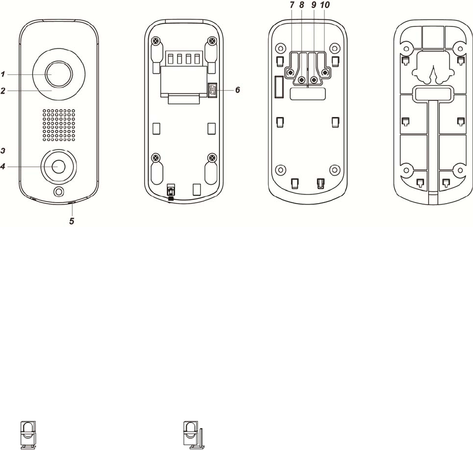
2.1. Parts Identification
1. Camera Lens
2. Night Light LED
3. LED Indicator (Blue / Amber)
4. Function Button
5. Bottom Screw
The bottom screw should be loosened before hooking the VDP onto mounting bracket, and
tightened after VDP is hooked to bracket.
When tightened, the bottom screw fixes VDP to mounting bracket. VDP cannot be detached
from bracket as long as screw is tightened.
6. Doorbell Jumper Switch
Jumper ON: Connect the Jumper Switch when using VDP with hardware doorbell.
Jumper OFF: Disconnect the Jumper Switch when not using VDP with hardware Doorbell.
7. 24V ADC Power Input
8. Doorbell Terminal
9. Doorbell Terminal
10. 24V ADC Power Input
Front View
Back View
(
Without Bracket
)
Bracket (Inside) Bracket (Outside)
Jumper On
The jumper link is inserted
connecting the two pins.
Jumper Off
If the jumper link is removed or
“parked” on one pin.

10
2.2. LED Indicator
The Video Door Phone has 2 sets of LED in Blue and Amber color, arranged in circular
pattern around the button to indicate device status.
LED Color Behavior Indication
Blue
Flash every 3 seconds VDP under Wi-Fi setup mode (AP mode)
Spinning VDP button pressed, waiting for answer
ON VDP under video streaming and two-way
communication
Amber
ON for 3 seconds VDP finish warm up upon power on,
entering normal operation.
Flash every 3 seconds Wi-Fi connectivity problem*
Flash every second VDP unable to connect to server
3 Flash then ON for 6
seconds
VDP reset to factory default
*Note: It takes about 1 minute for VDP to connect to Wi-Fi after power on. Before the
Wi-Fi connection is established, the Amber LED may flash momentarily.
2.3. The Power Supply
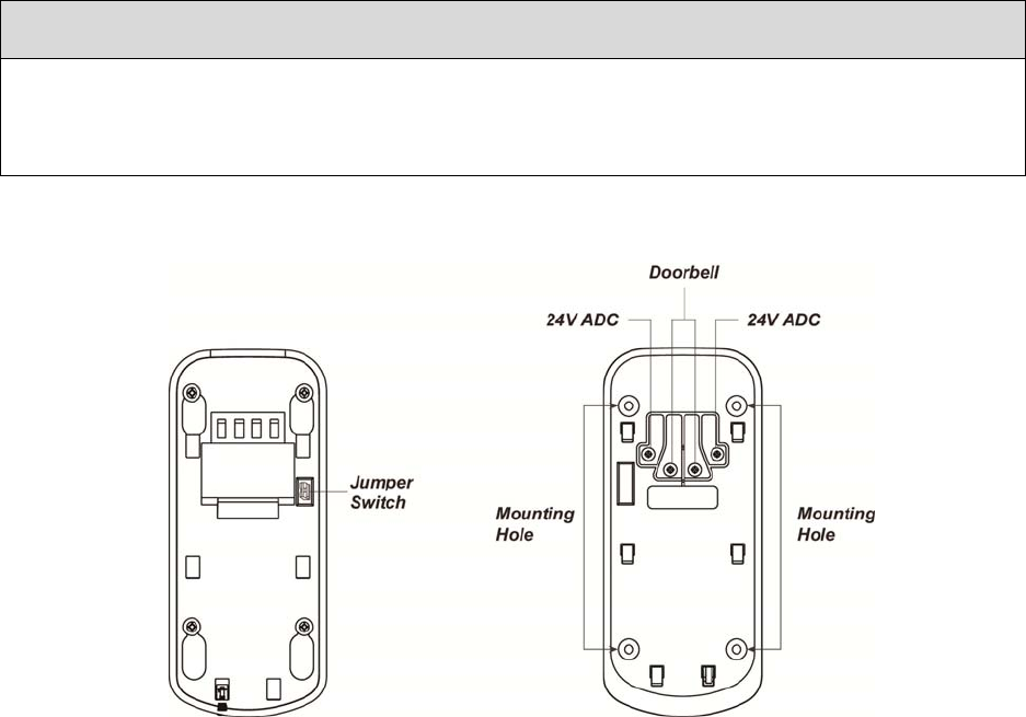
The VDP uses 24V±10% AC or DC power as power source. Connect power to the
connector on the bracket, install the VDP on the bracket to power on the device.
11
3. Getting Started
3.1. Equipment required
The following equipment is required to use VDP:
A Climax IP based security system alarm panel – The panel must be registered in
Climax Home Portal Server with a valid user account. Refer to panel and Home
Portal Server user guide to complete panel setup and registration process.
A router supporting 2.4 GHz Wi-Fi network. The Climax panel should be connected
to this router with access to internet and Home Portal Server.
An iPhone or Android smartphone with Climax Vesta Home 2 app installed.
Android version requirement: Android 5.1 or over.
iPhone version requirement: iOS 8 or over
3.2. Hardware Installation
1. Determine whether the VDP would be connected to a conventional doorbell.
If doorbell is used, connect the Jumper Switch.
If doorbell is not used, do NOT connect the Jumper Switch.
Warning
The Jumper Switch setting MUST be adjusted according to doorbell usage. Make sure
the jumper setting is correct before proceeding with installation. Incorrect setting may
cause damage to VDP when wiring.
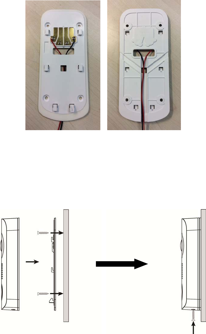
2. Find the wall mounting bracket, connect 24V±10% ADC power to the connector on
the bracket. If doorbell is used, also connect the door bell.
12
The wiring should connect to the connector on the inside of bracket, pass through
the opening on the bracket and tucked into the bracket’s central cavity on the back.
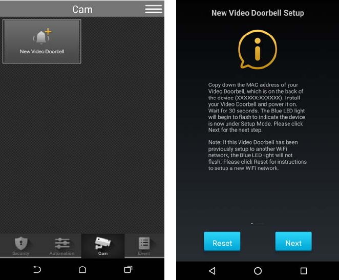
3. The wall mounting bracket has 4 mounting holes. Use the mounting holes as
template, mark mounting location on the wall, drill holes and insert wall plug if
needed.
4. Screw the mounting bracket onto marked location.
5. Hook VDP onto the bracket. When VDP is hooked on the bracket, the connect come
in contact with the device and VDP is powered on.
6. Tighten the bottom screw to lock VDP onto bracket.
13
3.3. Wi-Fi Setup and Learning
1 Use your smartphone to open Vesta Home 2 app and log into the user account
registered by the control panel.
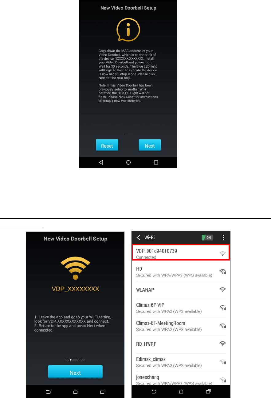
2 Select the Camera tab in the app. Press “New Video Doorbell” to begin setting.
3 Power up the Video Doorbell by applying AC power. The device will first warm up
for about 30 seconds, then the Blue LED will begin to flash.
Flashing Blue LED indicates the Video Doorbell does not have a working Wi-Fi
setting and it enter Wi-Fi setup mode (AP mode) automatically upon power up.
4 If the VDP has already finished Wi-Fi setting, it will not enter Wi-Fi setup mode upon
power up and must be reset to factory default. Follow procedure below to factory
reset:
a. Disconnect and reconnect AC power.
b. Press and hold VDP button as soon as AC power is reconnected. Do NOT wait
for warm up to complete.
c. Keep holding the button for about 25 seconds until VDP Amber LED flashes 3
times, then stays ON, then release the button.
d. Factory Reset is complete, VDP will reboot and enter W-Fi setup mode.
14
5 Leave the Vesta Home 2 TW app in the background and access your Smartphone’s
Wi-Fi setting function. Look for wireless network named VDP_XXXXXXXXXXXX.
(XXXXXXXXXXXX = device MAC address) Connect to this wire network, then
return to Vesta Home 2 TW app and continue.
If your smartphone warns the network has no internet access, ignore the warning
and proceed.
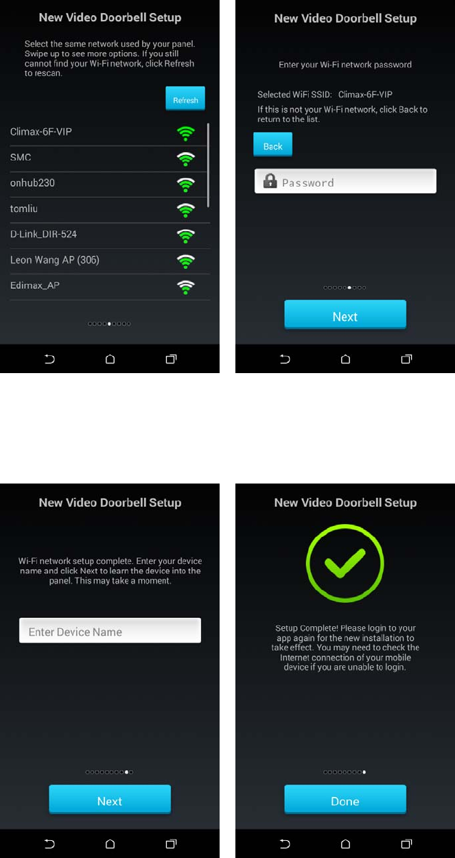
6 The app will search for available wireless network and display search result. Select
the wireless network desired and enter password to join the network.
If you encounter error message, check your smartphone wireless setting to make
sure the smartphone is still connected to the same VDP_XXXXXXXXXXXX network
15
previously selected, then return to app and search the available network again.
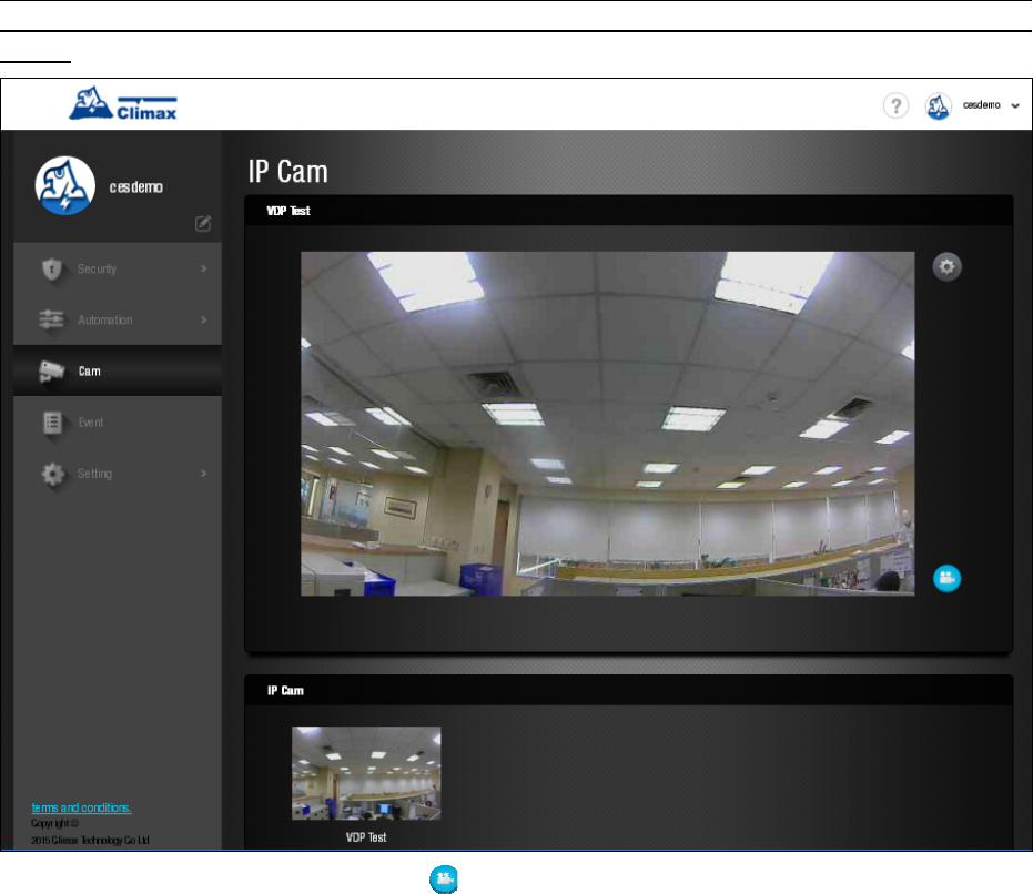
7 After successfully joining network, the app proceeds to learn the Video Doorbell into
the control panel. Enter the device name and proceed. When learning is complete,
the app displays success message. Press Done and re-login to the app to start
using Video Doorbell (The device will reboot upon complete learning, you may need
to wait a short time for it to restart.)
16
4. Operation
Operation of VDP should be performed via Climax Home Portal Server, using the
account registered by the Control Panel which VDP is learnt into.
4.1. Web Browser Access
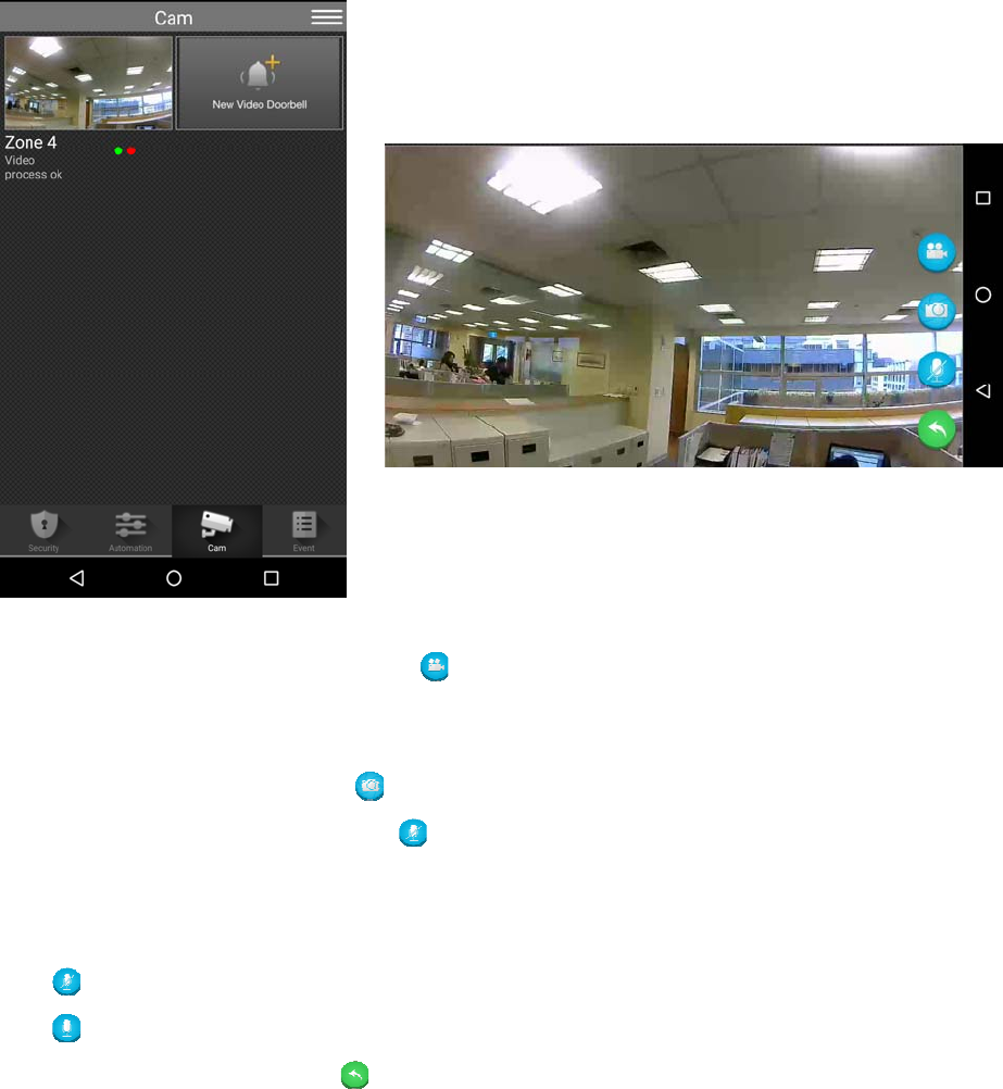
When accessing the Home Portal Server account using a web browser, VDP is located
under the Camera page and has the same function of a Climax IP Camera.
Two-way voice and doorbell functions are not enabled for web browser access. To uses
these functions, a smartphone app is required. Please see 4.2. Smartphone Access for
detail.
Press the Record Video button to record a video clip.
.
17
4.2. Smartphone Access
Smartphone application access to VDP provides two-way voice and doorbell push
notification function.
Log into Home Portal Account and select Cam page to display VDP streaming thumbnail.
Press the thumbnail image to enlarge to full screen.
The VDP full screen has 4 function buttons:
Press the Record Video button to record a video clip.
The video clip length is set to 30 seconds by default, composed of 10 seconds
before button press and 20 seconds after button press.
Press the Camera button to take a single picture.
Press the Microphone button to toggle smartphone microphone.
Full screen VDP streaming will open voice channels automatically, allowing
smartphone user to converse with VDP. Use the microphone button to control
smartphone microphone and switch between one-way and two-way voice channel.
: Smartphone microphone OFF – One-way listen-in only.
: Smartphone Microphone ON – Two-way voice communication.
Press the Return button to return to camera thumbnail page.

18
4.3. Doorbell Notification
The Doorbell Notification function allows VDP to inform the user remotely when its
doorbell button is pressed. With Doorbell Notification, the user will be able to answer the
doorbell remotely and converse with the guest via VDP using the smartphone even
when away from home.
Before using the Doorbell Notification, the following settings should be completed:
The VDP must be properly setup and learnt into Control Panel, as described in
previous chapter.
The Control Panel Home Portal Server account should be registered and working
properly.
The Control Panel Home Portal Server account’s push notification setting must be
enabled. To enable push notification function, Log into the Home Portal Server
account and select Notification setting.
1 Press the doorbell button on VDP, VDP will sound a door chime. If any hard wired
doorbell is connected to VDP, the doorbell will also be activated; the Blue LED will
start spinning.
2 The user will receive a push notification message from its panel Home Portal Server
Account, titled “Doorbell”
3 Press on the push notification message, the smartphone will launch Vesta Home 2
TW app and log into registered account automatically. After login, the app will
automatically jump to VDP page. VDP Blue LED will turn to steady ON to indicate.
4 After finishing conversation, press the return button to return to camera thumbnail
page.
<
<N
NO
OT
TE
E>
>
If the Doorbell Notification is not answered within 1 minute after button press,
the VDP will time out and the Blue LED will stop spinning
When the button is pressed, VDP will take a picture which will be uploaded to
the Home Portal Server.

19
4.4. Video / Picture Capture
VDP will take a picture or video during following occasions. All pictures and video clips
taken will be uploaded to the server.
Picture
Press the function button in front of VDP to take a picture
Press the camera icon on the app when streaming video to take a picture
Video
Press the record video icon on the app or server webpage UI to record a video
Whenever an alarm is activated by the Control Panel, VDP will record a video
immediately.
20
5. Programming
VDP setting program should be programmed via Home Portal Server web browser UI.
5.1. Video Setting
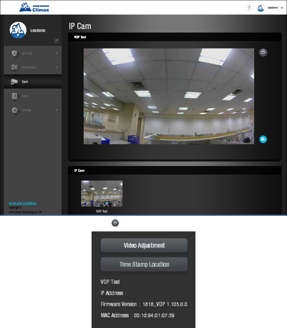
Video Setting options are accessed on the Home Portal Server web UI’s Camera page.
Press the Video Setting icon to adjust video configuration:
21
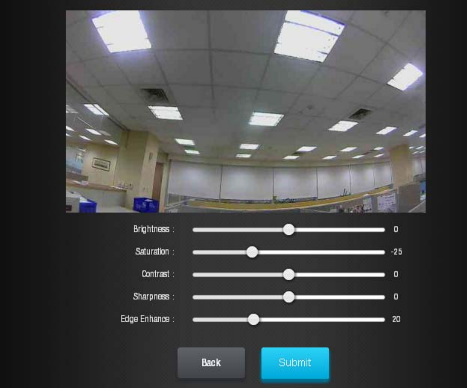
Video Adjustment: For image tuning.
22
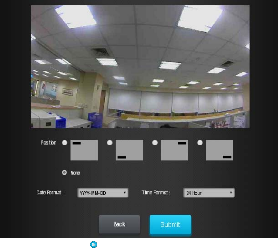
Time Stamp: Select the time stamp location on video.
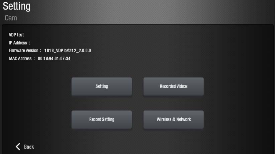
Press the Record icon to record a video clip
23
5.2. VDP Setting
VDP’s own setting options are accessed on the Home Portal Server web UI’s Edit
Device page.
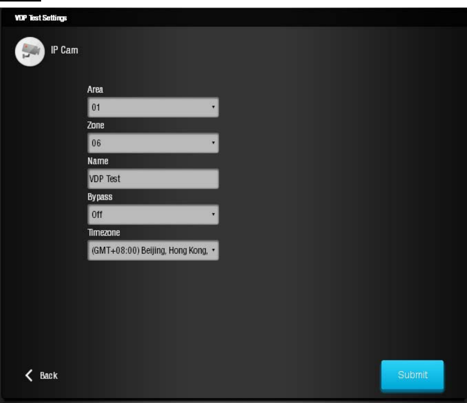
24
Setting
The setting page is used to set VDP zone number, device name and time zone
setting. Please refer to your Control Panel’s configuration webpage for option detail.
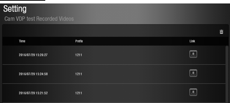
25
Recorded Video
The Recorded Video page stores video clips previously taken by VDP for download.
Click the download link icon to down the file into your computer.
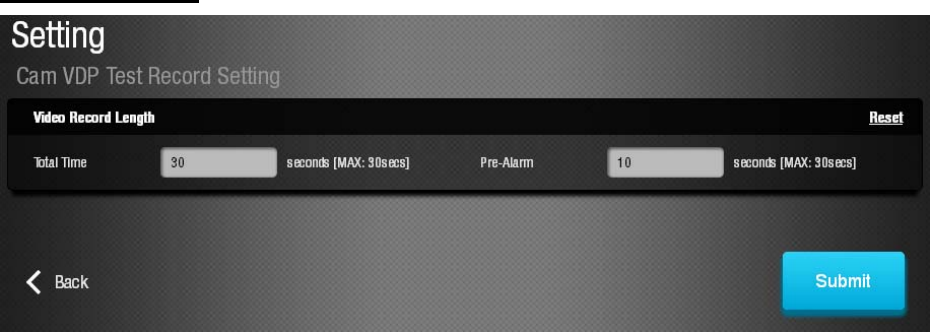
26
Recorded Setting
The Recorded setting page determines the video clip length when VDP is activated to
record a video.
Total Time:
The total time length of each recorded video (Default: 30 seconds)The total video
time length.
Pre-alarm:
This function is disabled for VDP, please ignore.
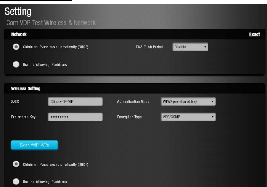
27
Wireless and Network
The Wireless Network webpage display current VDP Wi-Fi setting.
Wi-Fi setting can only be changed by factory resetting VDP and using Vesta Home 2 TW
app to reprogram Wi-Fi setting. Wi-Fi setting cannot be changed on the webpage.
.
28
6. Local Programming Webpage
VDP also supports local programming webpage which may be access via LAN after
completing Wi-Fi setting.
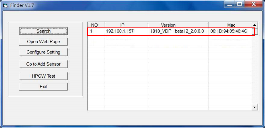
In order to locate VDP on local network, a specific “Finder” software is provided by
Climax to locate VDP on LAN. To install the “Finder” software”
Step 1. Insert the supplied CD-ROM into your CD-ROM drive
Step 2. Find the Finder software in the CD-ROM. Install and execute the Finder.
Step 3. Finder will automatically search for VDP on LAN and display its information. If
available, the camera’s LAN IP address, Firmware version and MAC address will be
displayed
If VDP is not displayed, check VDP AC power and make sure its Wi-Fi is properly
setup and click “Search” to update the panel information.
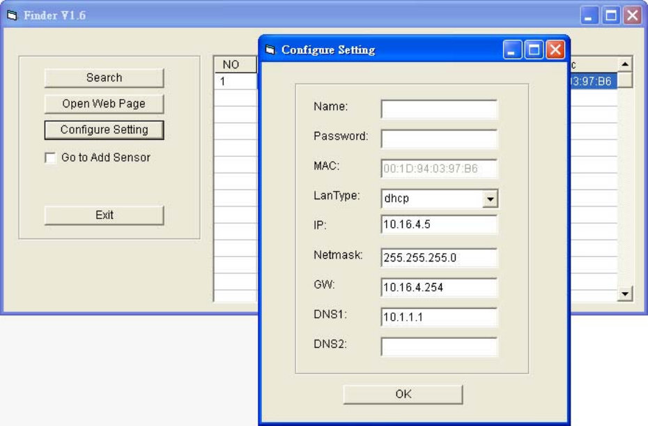
Step 4. (Optional)You can choose to edit the camera’s network setting manually by clicking
on the panel column, then click “Configure Setting”
29
The LanType is default to DHCP and does not require manual input of
IP/Netmask/Gateawy/DNS setting. If you wish to configure these setting manually,
change LanType to Static.
After finish changing network setting, enter the user name (default: admin) and
password (default: cX+HsA*7F1) then click OK to confirm. The user name and
password can be changed later in the camera’s configuration webpage
Step 5. Click the camera information column and click on “Open Web Page”, or double click
on the camera column to link to the panel configuration webpage. Your default
browser will start automatically to connect to the LAN IP displayed in Finder.
30
6.1. Connecting to Webpage
If default login user/password is not changed, webpage login will be disabled 1 hour after
power on. Please reboot the camera and retry connection.
Step 1. Double click the VDP column on Finder, or enter VDP’s LAN IP Address in your
browser.
Step 2. Enter the login username and password
Default username: admin
Default password: cX+HsA*7F1
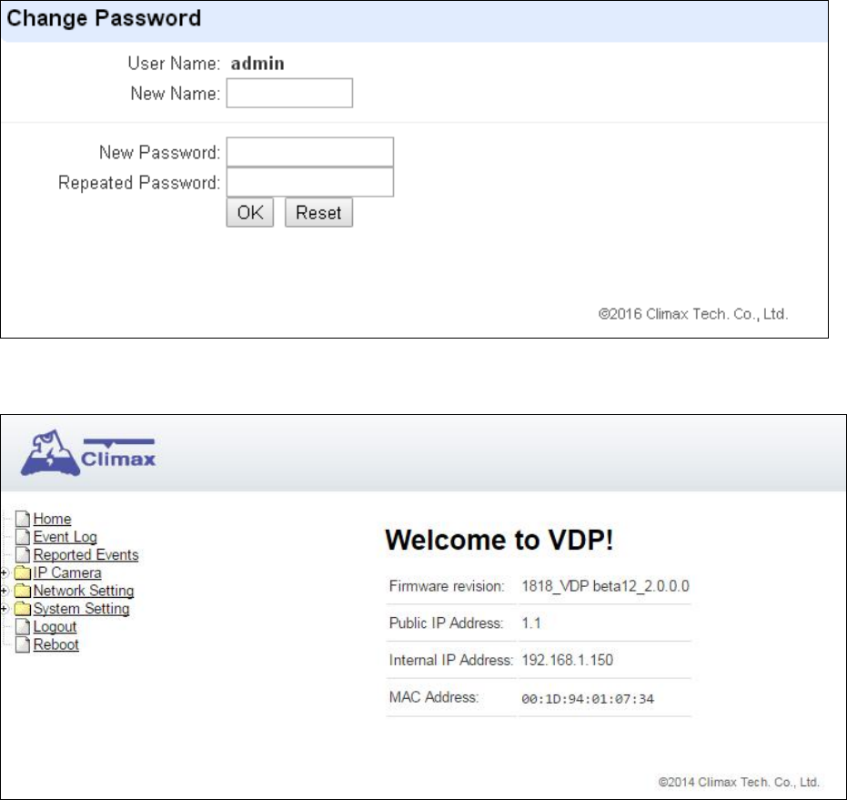
tep 3. You will enter change password page. Enter and repeat a new password (username
change is optional), take care that both username and password are case sensitive.
Click OK to confirm.
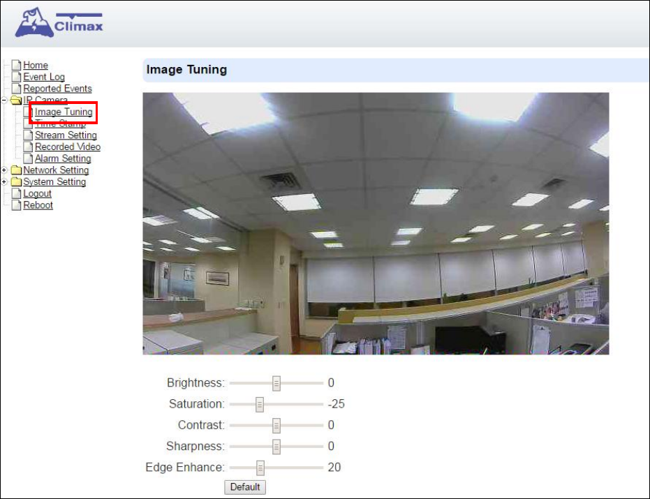
Step 4. Upon confirming new username and password. You will enter camera Welcome page.
The camera will prompt you to re login with new username and password.
The Welcome page displays camera info. Click on the pages and folders on the left to access
the camera’s various functions
31
7. IP Camera
The “IP Camera” folder on the left panel includes configuration webpages for you to
manage your VDP and view videos.
7.1. Image Tuning
Click on “Image Tuning” to adjust video preferences according to the below
parameters:
32
7.2. Time Stamp
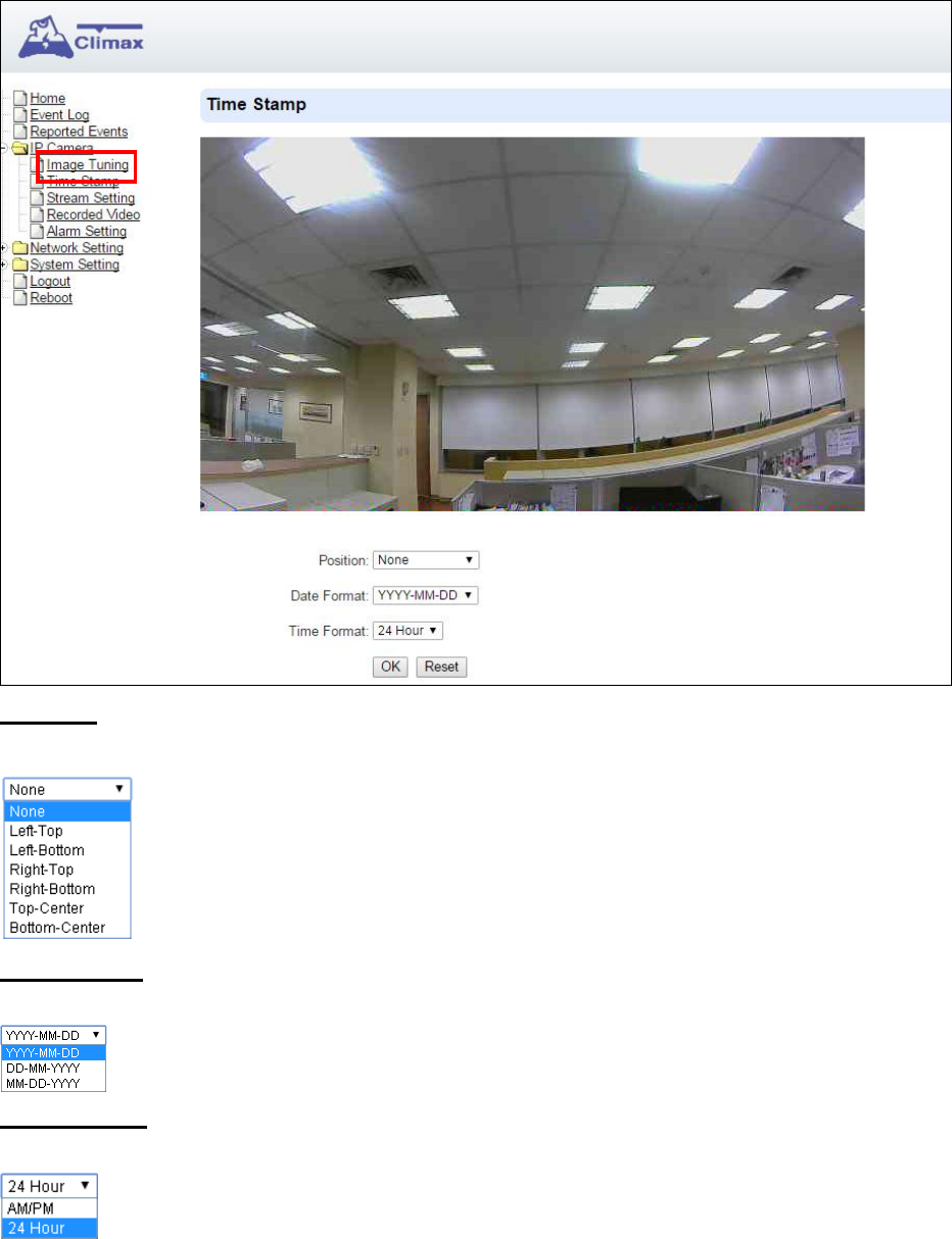
The “Tim Stamp” webpage is for you to edit the Time Stamp format and location on the
video.
Position
The available options are:
Date Format
The available options are:
Time Format
The available options are:
Press “OK” to submit your adjusted parameters. Press “Reset” to re-select the
parameters.
33
7.3. Stream Setting
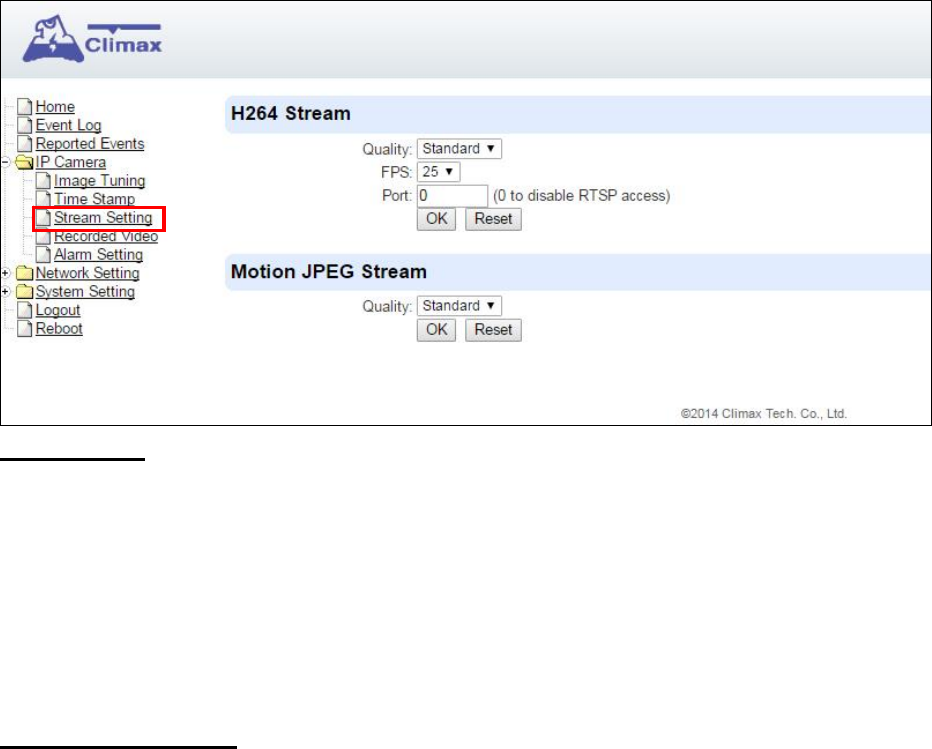
The “Stream Setting” webpage determines quality of video streaming, and the port to
be used when VDP is access remotely via Port Forwarding.
H264 Stream
Quality adjusts the quality of the stream.
Frames Per Second (FPS) are adjustable. Increasing FPS improves the quality of the
live-stream. Click “OK” to confirm changes or click “Reset” to reset to the previously set
parameters.
Port: The port number for obtaining HD 1280x720 resolution H264 video stream. The
factory default is set to 0 and RTST access is disabled. To enable RTSP function, please
set a port number.
Motion JPEG Stream
Quality adjusts the quality of the stream.

34
7.4. Recorded Files
This menu displays all the recorded files. The VDP has 20 mega-byte storage space for
recorded video clips. The video files are stored in the camera’s RAM memory and will be
cleared if the camera is powered down.
Click on the buttons for the respective functions described below:
All: to select all the recorded videos.
None: to cancel selecting the recorded videos.
Half Old: to select the older half the recorded videos.
Invert: to invert the current selection. E.g. if “All” was selected, clicking “Invert” will
clear all selections.
Delete: to delete the currently selected (ticked) video.
Video link: to download or play the video.
35
7.5. Alarm Setting
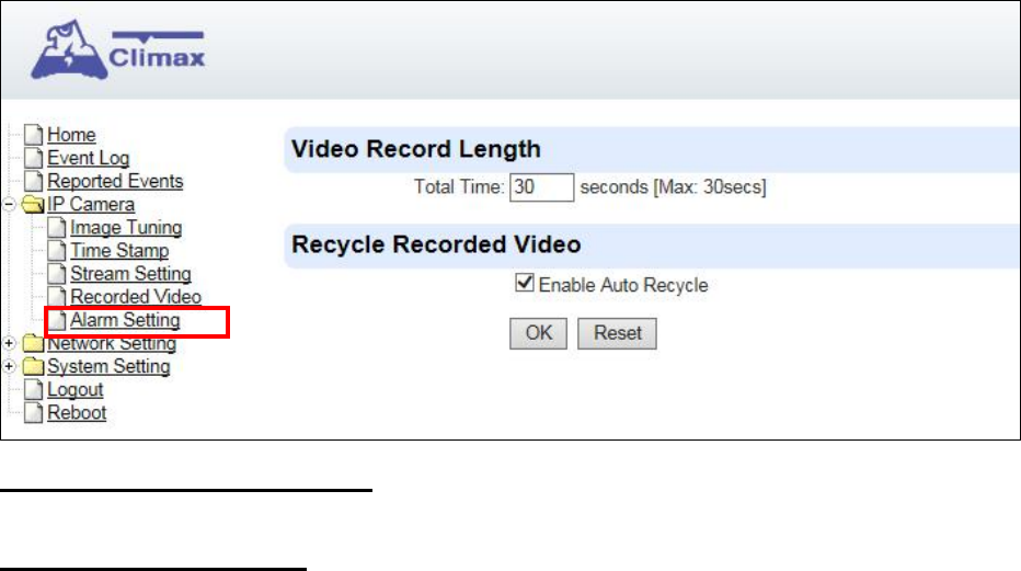
This menu displays the video recording options.
Video Record Length settings
Total Time: The total time length of each recorded video (Default: 30 seconds).
Recycle Recorded Video
When this option is enabled, VDP will automatically delete the oldest videos to clear
storage space in the camera when the memory is full
Press “OK” to submit the updated programmed parameters. Or press “Reset” to
re-enter (“Reset” button resets the parameters to the previously set parameters).
36
8. Network Setting
8.1. Network
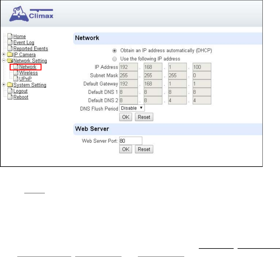
The following is displayed when you click on “Network” under the “Network Setting”
option:
Obtain an IP address automatically (DHCP)
If DHCP is selected, the Network will obtain an IP address automatically with a
valid Network DHCP Server. Therefore, manual settings are not required.
This is only to be chosen if your Network environment supports DHCP. It will
automatically generate all information.
Use following IP address
You can also enter the Network information manually for IP Address, Subnet Mask,
Default Gateway, Default DNS 1 and Default DNS 2.
DNS Flush Period
You can set the system to clear current DNS resolution records for all entered URL
settings (Reporting, Upload, XMPP…etc.) after a set time period. The system will
then resolve the Domain Name again and acquire new IP address for the URL
settings. This function is disabled by default.
Web Server
Set the port used to access VDP’s webpage. VDP will reset upon changing the web
server port. After reset is complete, VDP will switch to using the new port number
when opening its webpage.
37
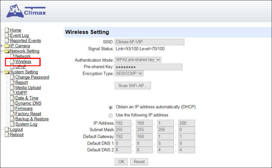
8.2. Wireless
The “Wireless” webpage display current VDP Wi-Fi setting.
Wi-Fi setting can only be changed by factory resetting VDP and using Vesta Home 2 TW
app to reprogram Wi-Fi setting. Wi-Fi setting cannot be changed on the webpage.
38
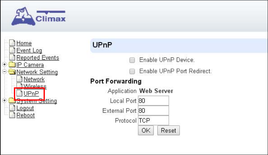
8.3. UPnP
The following is displayed when you click on “UPnP”
UPnP stands for Universal Plug and Play, which opens network architecture that
leverages TCP/IP and the web technologies to enable seamless proximity networking in
addition to control and data transfer among networked devices at home, office or public
spaces. You can configure this setting to allow for Port Forwarding connection to VDP
Enable UPnP Device:
When enabled, you will be able to see this device via any UPnP discovery tool
Enable UPnP Port Redirect:
The device will try to find an UPnP-supported router and set up the port to redirect to the
router.
Port Forwarding:
1. Local Port
2. External Port
3. Protocol
39
9. System Setting
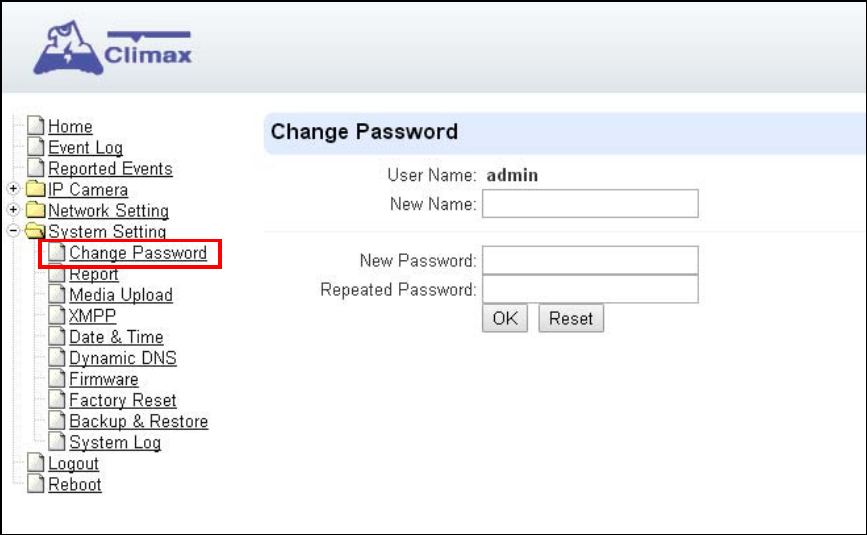
9.1. Change Password
Edit the username and password used to log into VDP webpage under “Change
Password” page.
Enter a new name or new password and click “OK” to confirm the username and
password change. The username and password are case sensitive.
40
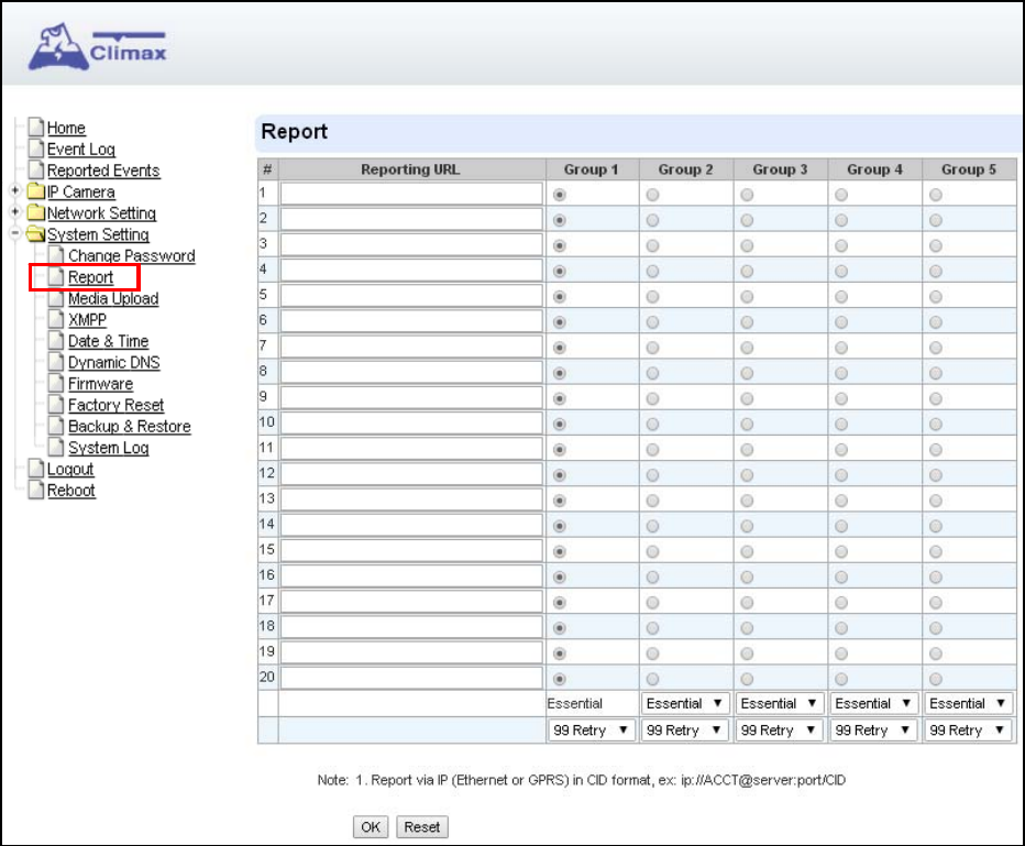
9.2. Report
The report function for VDP is reserved for use.
Reporting URL
41
9.3. Media Upload
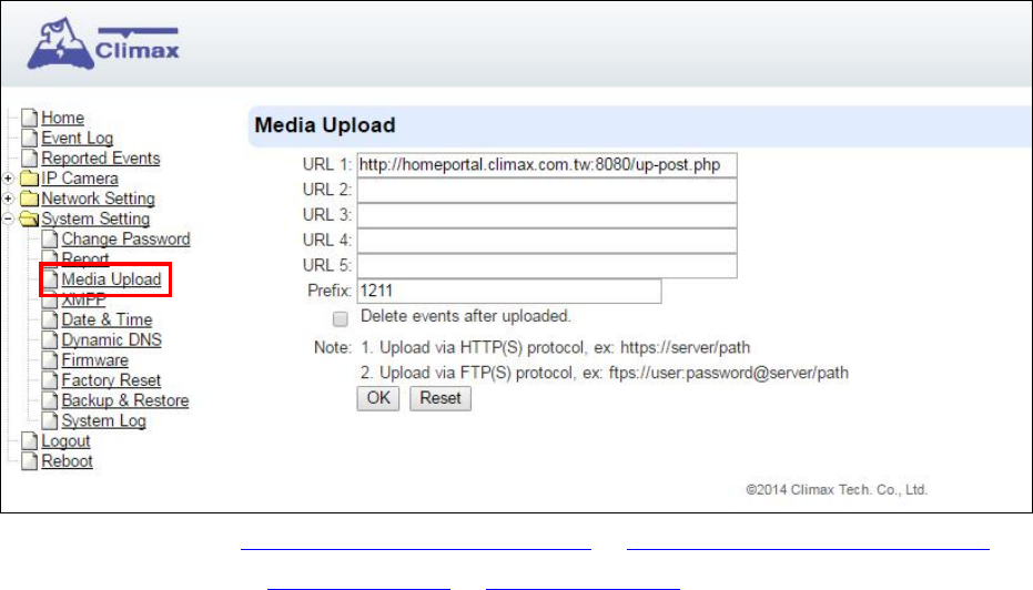
Program the camera’s captured video upload destination under “Media Upload” page.
Upload to FTP: ftp://user.password@server/path or ftps://user.password@server/path
Upload to server: http://server/path or https://server/path
After the camera has been learnt into Control Panel, the first upload URL will be
programmed automatically according to panel setting. Do NOT change this setting or it
will cause video upload to server to fail..
42
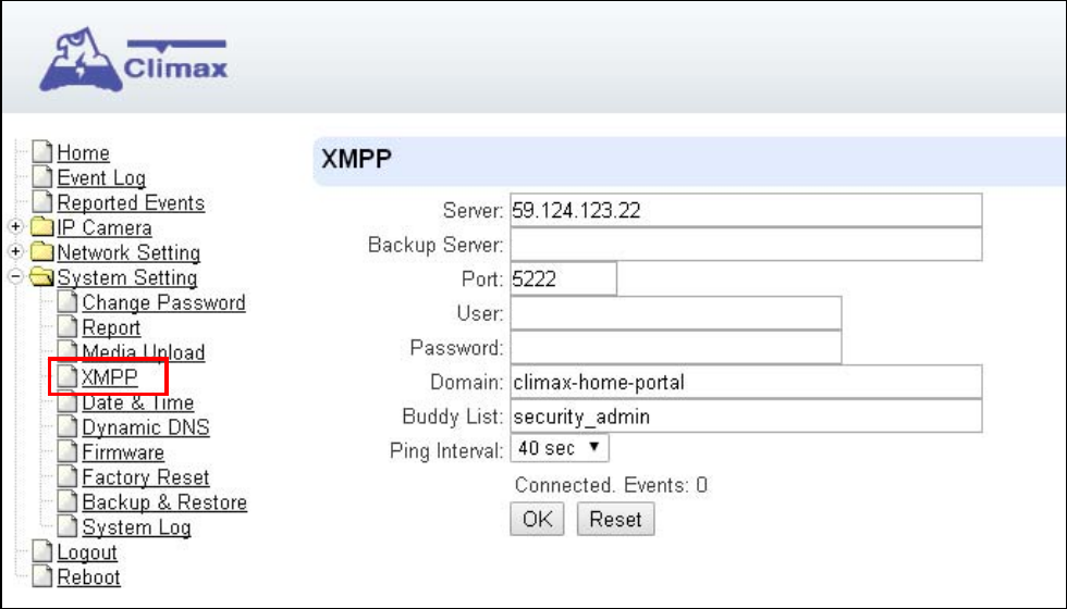
9.4. XMPP
The “XMPP” page allows the camera to connect to the Home Portal™ Server for remote
control. Please do not modify any settings or the camera may lose connection with
Home Portal Server.
43
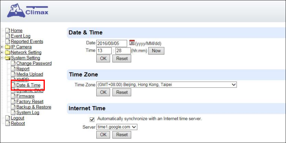
9.5. Date & Time
The following page is displayed when you click on “Date & Time”:
Under the Date & Time heading, you can edit time and date. As the page does not
automatically refresh itself with the time, you can click on “Now” to refresh to your
current time.
Under the Time Zone heading, you can choose your time zone.
Under the Internet Time heading, you can tick the box “Automatically synchronize with
an Internet time server” to adjust to internet time. The scroll down bar of “Server” allows
you to choose from a selection of time servers.
Click on “OK” to confirm the settings.
44
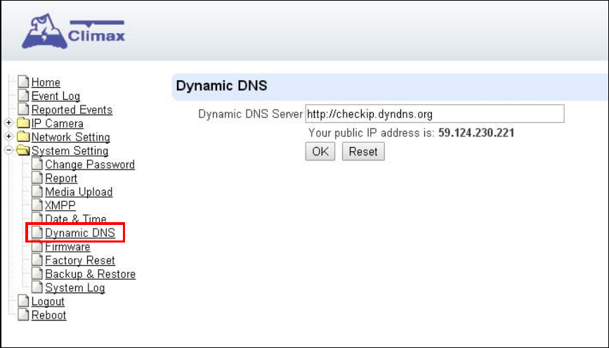
9.6. Dynamic DNS
The “Dynamic DNS” page provides VDP public IP information.
Dynamic DNS Server: Set the server used by VDP to acquire its public IP address.
Public IP address: The public IP address shown is required to for remote access
of the VDP via port forwarding.
45
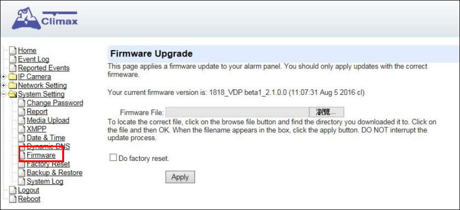
9.7. Firmware
The following page is displayed when you click on “Firmware”
You can update VDP firmware: Click the “Choose File” button, browse and find the
correct file, and press “Apply” to apply the setting. Please follow the onscreen
instruction to complete the update. It is also recommended to select “Do factory reset
(recommended)” when upgrading a firmware.
46
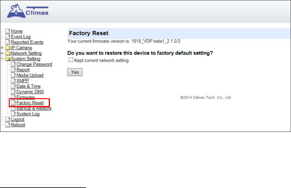
9.8. Factory Reset
Factory Reset function will clear all VDP setting, event records and restore all settings to
factory default.
You can choose to reset VDP to the factory default setting by clicking the “Yes” button.
After factory reset, delete VDP from panel device list, then user the Vesta Home 2 app to
setup VDP WiFI and learn VDP into panel again.
Hardware Factory Reset
1. Disconnect and reconnect AC power.
2. Press and hold VDP button as soon as AC power is reconnected. Do NOT wait for
warm up to complete.
3. Keep holding the button for about 25 seconds until VDP Amber LED flashes 3 times,
then stays ON, then release the button.
4. Factory Reset is complete, VDP will reboot and enter W-Fi setup mode.
47
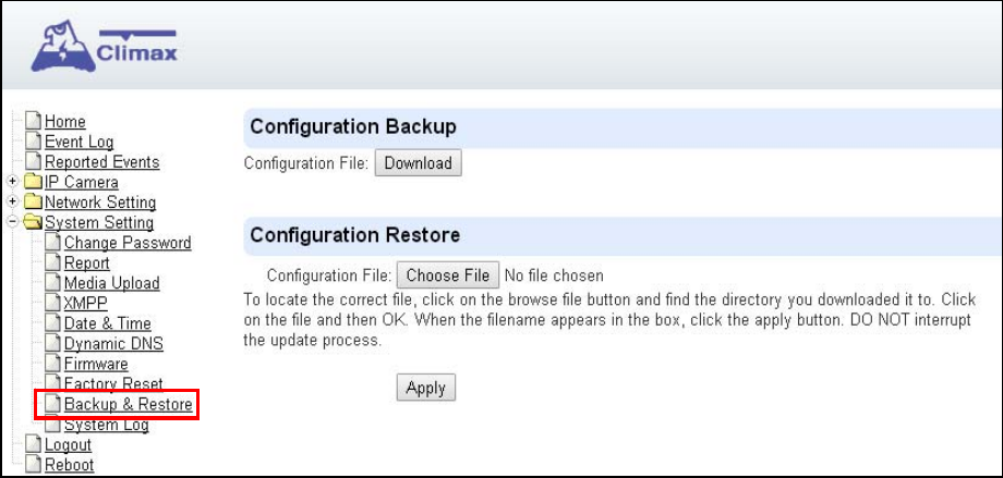
9.9. Backup & Restore
You can store the current settings by clicking on the “Download” button.
If you wish to restore the previously stored file, click on “Choose File”, find the correct
file and click on “Apply” to restore to the previous setting.
48
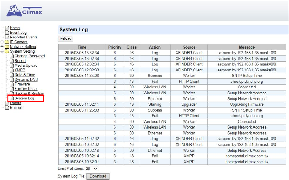
9.10. System Log
The “System Log” displays system operation history.
You can choose how many reported events are displayed by selecting the drop down
bar near the bottom of the page, or click “Download” button to download detailed
system log file into your computer.

49
9.11. Logout
Click “Logout” and confirm the action to disconnect from VDP webpage.
9.12. Reboot
The Reboot function allows you to restart the VDP. Press “Reboot” and confirm, VDP
will automatically start rebooting process and countdown the remaining time.
50
10. History
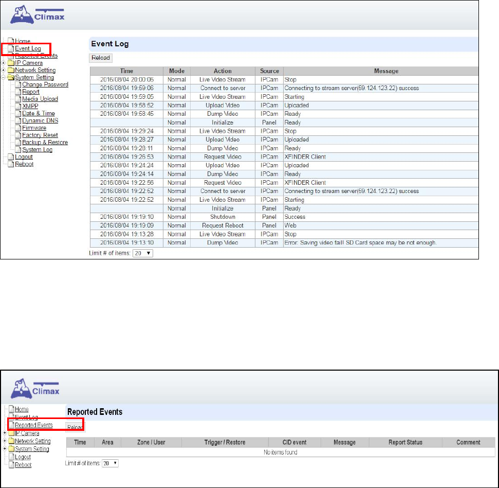
10.1. Event Log
The Event Log records system events.
You can choose how many events are displayed on the page by selecting the drop down
bar near the bottom of the page.
10.2. Reported Events
The Reported Event page is reserved.
You can choose how many reported events are displayed by selecting the drop down
bar near the bottom of the page.
51
I. Federal Communication Commission Interference Statement
This equipment has been tested and found to comply with the limits for a Class B digital device,
pursuant to Part 15 of the FCC Rules. These limits are designed to provide reasonable protection
against harmful interference in a residential installation.
This equipment generates, uses and can radiate radio frequency energy and, if not installed and
used in accordance with the instructions, may cause harmful interference to radio
communications. However, there is no guarantee that interference will not occur in a particular
installation. If this equipment does cause harmful interference to radio or television reception,
which can be determined by turning the equipment off and on, the user is encouraged to try to
correct the interference by one of the following measures:
. Reorient or relocate the receiving antenna.
. Increase the separation between the equipment and receiver.
. Connect the equipment into an outlet on a circuit different from that to which the receiver is
connected.
. Consult the dealer or an experienced radio/TV technician for help.
FCC Caution: To assure continued compliance, any changes or modifications not expressly
approved by the party responsible for compliance could void the user's authority to operate this
equipment. (Example - use only shielded interface cables when connecting to computer or
peripheral devices).
FCC Radiation Exposure Statement
This equipment complies with FCC RF radiation exposure limits set forth for an uncontrolled
environment. This equipment should be installed and operated with a minimum distance of 20
centimeters between the radiator and your body.
This transmitter must not be co-located or operating in conjunction with any other antenna or
transmitter.
The antennas used for this transmitter must be installed to provide a separation distance of at
least 20 cm from all persons and must not be co-located or operating in conjunction with any
other antenna or transmitter.
This device complies with Part 15 of the FCC Rules. Operation is subject to the following two
conditions:
(1) This device may not cause harmful interference, and
(2) This device must accept any interference received, including interference that may cause
undesired operation.