Climax Technology Co WSSZB Smart Scenario Switch User Manual WSS 4E ZBS 20161205 FCCx
Climax Technology Co Ltd Smart Scenario Switch WSS 4E ZBS 20161205 FCCx
UserManual.wiki
>
Climax Technology Co
>
WSSZB User Manual
Users Manual
Navigation menu
Upload a User Manual
Namespaces
Wiki Guide
HTML
PDF
Info
Views
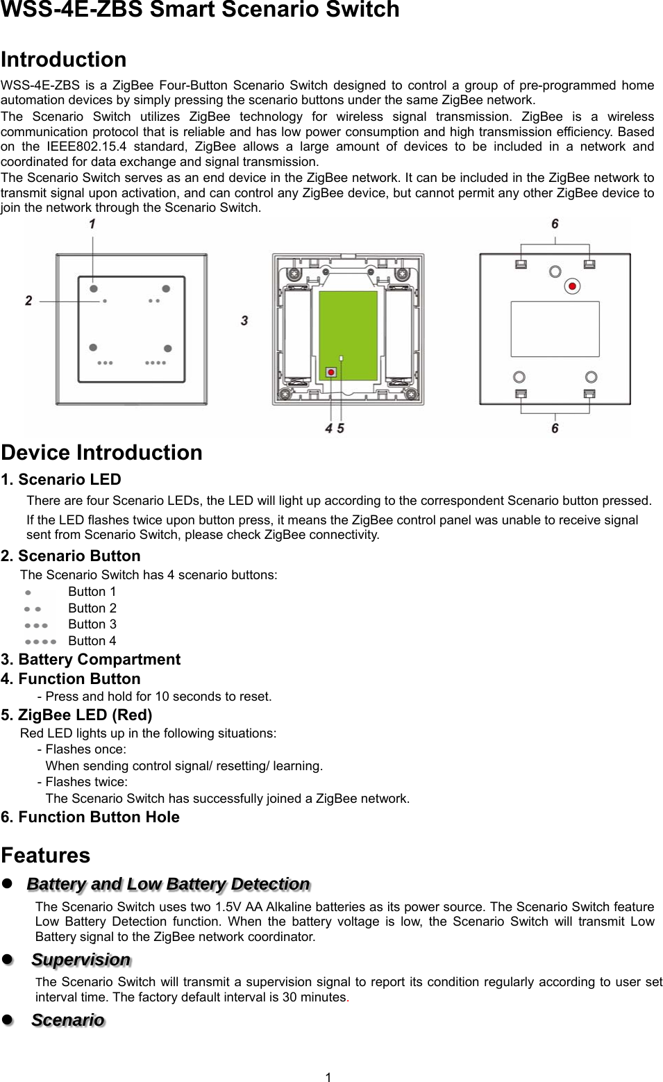
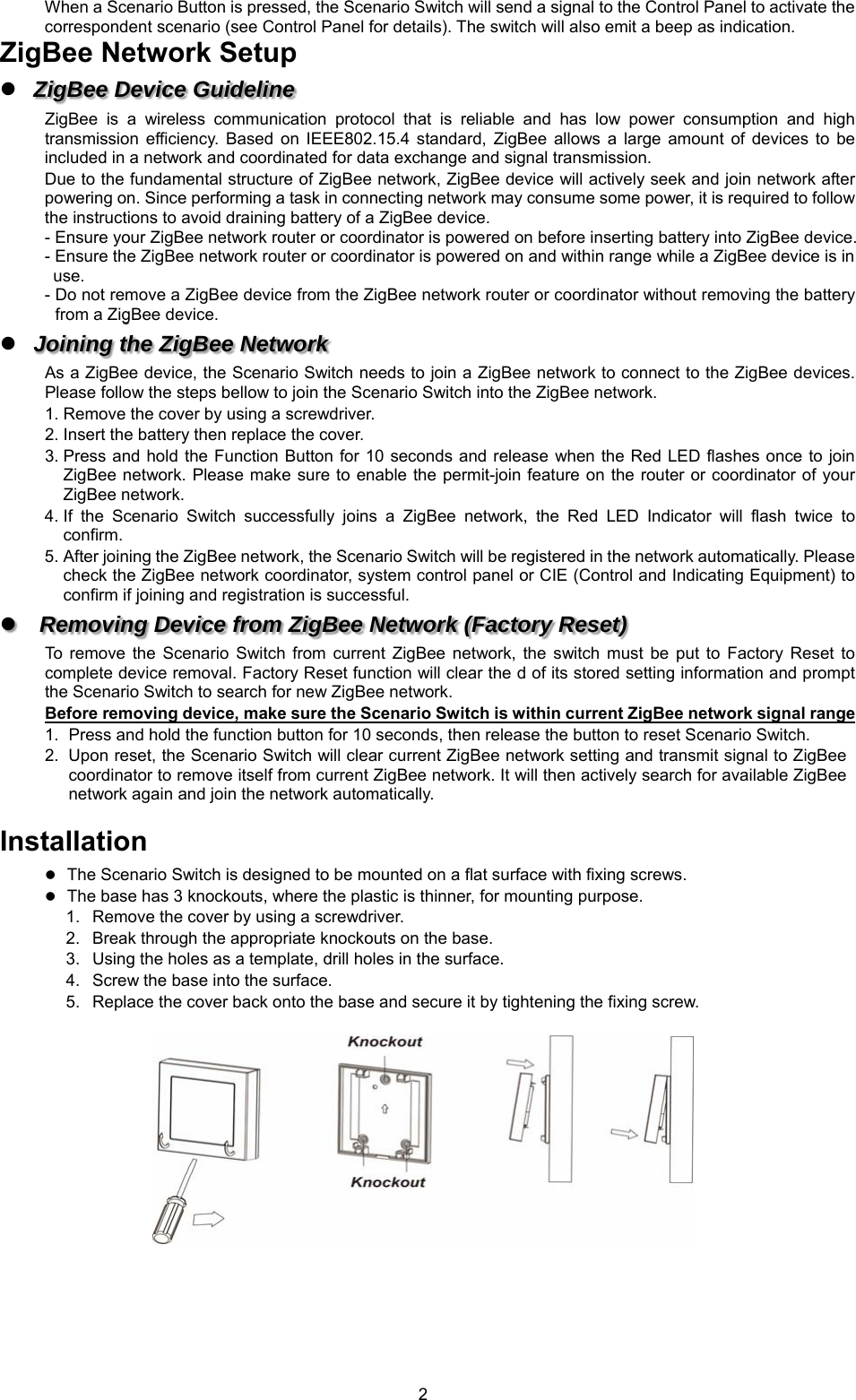
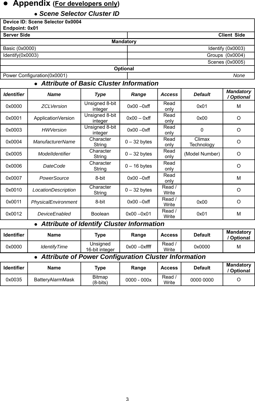
User Manual
Discussion / Help
Navigation