Climax Technology Co WSSZB Smart Scenario Switch User Manual WSS 4E ZBS 20161205 FCCx
Climax Technology Co Ltd Smart Scenario Switch WSS 4E ZBS 20161205 FCCx
Users Manual
1
WSS-4E-ZBS Smart Scenario Switch
Introduction
WSS-4E-ZBS is a ZigBee Four-Button Scenario Switch designed to control a group of pre-programmed home
automation devices by simply pressing the scenario buttons under the same ZigBee network.
The Scenario Switch utilizes ZigBee technology for wireless signal transmission. ZigBee is a wireless
communication protocol that is reliable and has low power consumption and high transmission efficiency. Based
on the IEEE802.15.4 standard, ZigBee allows a large amount of devices to be included in a network and
coordinated for data exchange and signal transmission.
The Scenario Switch serves as an end device in the ZigBee network. It can be included in the ZigBee network to
transmit signal upon activation, and can control any ZigBee device, but cannot permit any other ZigBee device to
join the network through the Scenario Switch.
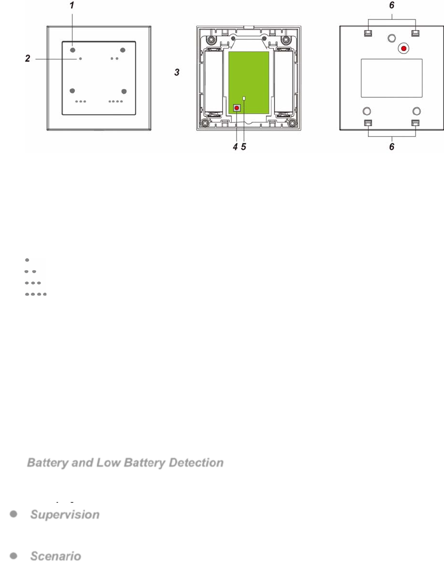
Device Introduction
1. Scenario LED
There are four Scenario LEDs, the LED will light up according to the correspondent Scenario button pressed.
If the LED flashes twice upon button press, it means the ZigBee control panel was unable to receive signal
sent from Scenario Switch, please check ZigBee connectivity.
2. Scenario Button
The Scenario Switch has 4 scenario buttons:
Button 1
Button 2
Button 3
Button 4
3. Battery Compartment
4. Function Button
- Press and hold for 10 seconds to reset.
5. ZigBee LED (Red)
Red LED lights up in the following situations:
- Flashes once:
When sending control signal/ resetting/ learning.
- Flashes twice:
The Scenario Switch has successfully joined a ZigBee network.
6. Function Button Hole
Features
Battery and Low Battery Detection
The Scenario Switch uses two 1.5V AA Alkaline batteries as its power source. The Scenario Switch feature
Low Battery Detection function. When the battery voltage is low, the Scenario Switch will transmit Low
Battery signal to the ZigBee network coordinator.
Supervision
The Scenario Switch will transmit a supervision signal to report its condition regularly according to user set
interval time. The factory default interval is 30 minutes.
Scenario
2
When a Scenario Button is pressed, the Scenario Switch will send a signal to the Control Panel to activate the
correspondent scenario (see Control Panel for details). The switch will also emit a beep as indication.
ZigBee Network Setup
ZigBee Device Guideline
ZigBee is a wireless communication protocol that is reliable and has low power consumption and high
transmission efficiency. Based on IEEE802.15.4 standard, ZigBee allows a large amount of devices to be
included in a network and coordinated for data exchange and signal transmission.
Due to the fundamental structure of ZigBee network, ZigBee device will actively seek and join network after
powering on. Since performing a task in connecting network may consume some power, it is required to follow
the instructions to avoid draining battery of a ZigBee device.
- Ensure your ZigBee network router or coordinator is powered on before inserting battery into ZigBee device.
- Ensure the ZigBee network router or coordinator is powered on and within range while a ZigBee device is in
use.
- Do not remove a ZigBee device from the ZigBee network router or coordinator without removing the battery
from a ZigBee device.
Joining the ZigBee Network
As a ZigBee device, the Scenario Switch needs to join a ZigBee network to connect to the ZigBee devices.
Please follow the steps bellow to join the Scenario Switch into the ZigBee network.
1. Remove the cover by using a screwdriver.
2. Insert the battery then replace the cover.
3. Press and hold the Function Button for 10 seconds and release when the Red LED flashes once to join
ZigBee network. Please make sure to enable the permit-join feature on the router or coordinator of your
ZigBee network.
4. If the Scenario Switch successfully joins a ZigBee network, the Red LED Indicator will flash twice to
confirm.
5. After joining the ZigBee network, the Scenario Switch will be registered in the network automatically. Please
check the ZigBee network coordinator, system control panel or CIE (Control and Indicating Equipment) to
confirm if joining and registration is successful.
Removing Device from ZigBee Network (Factory Reset)
To remove the Scenario Switch from current ZigBee network, the switch must be put to Factory Reset to
complete device removal. Factory Reset function will clear the d of its stored setting information and prompt
the Scenario Switch to search for new ZigBee network.
Before removing device, make sure the Scenario Switch is within current ZigBee network signal range
1. Press and hold the function button for 10 seconds, then release the button to reset Scenario Switch.
2. Upon reset, the Scenario Switch will clear current ZigBee network setting and transmit signal to ZigBee
coordinator to remove itself from current ZigBee network. It will then actively search for available ZigBee
network again and join the network automatically.
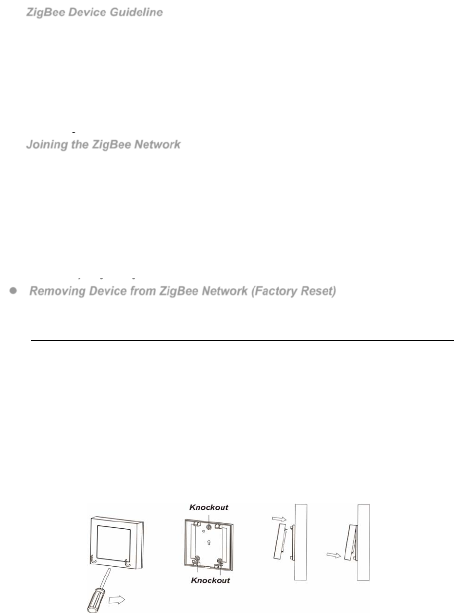
Installation
The Scenario Switch is designed to be mounted on a flat surface with fixing screws.
The base has 3 knockouts, where the plastic is thinner, for mounting purpose.
1. Remove the cover by using a screwdriver.
2. Break through the appropriate knockouts on the base.
3. Using the holes as a template, drill holes in the surface.
4. Screw the base into the surface.
5. Replace the cover back onto the base and secure it by tightening the fixing screw.

3
Appendix (For developers only)
Scene Selector Cluster ID
Device ID: Scene Selecto
r
0x0004
Endpoint: 0x01
Server SideClient Side
Mandatory
Basic (0x0000)Identify (0x0003)
Identify(0x0003)Groups (0x0004)
Scenes (0x0005)
Optional
Power Configuration(0x0001)None
Attribute of Basic Cluster Information
IdentifierNameTypeRangeAccess DefaultMandatory
/ Optional
0x0000ZCLVersionUnsigned 8-bit
integer 0x00 –0xffRead
only 0x01M
0x0001ApplicationVersionUnsigned 8-bit
integer 0x00 – 0xffRead
only 0x00O
0x0003HWVersionUnsigned 8-bit
integer 0x00 –0xffRead
only 0O
0x0004ManufacturerNameCharacter
String 0 – 32 bytesRead
only
Climax
TechnologyO
0x0005ModelIdentifierCharacter
String 0 – 32 bytesRead
only (Model Number)O
0x0006DateCodeCharacter
String 0 – 16 bytesRead
only
O
0x0007PowerSource8-bit0x00 –0xffRead
only M
0x0010LocationDescriptionCharacter
String 0 – 32 bytesRead /
Write O
0x0011PhysicalEnvironment8-bit0x00 –0xffRead /
Write 0x00O
0x0012DeviceEnabledBoolean0x00 –0x01Read /
Write 0x01M
Attribute of Identify Cluster Information
IdentifierNameTypeRangeAccess DefaultMandatory
/ Optional
0x0000IdentifyTimeUnsigned
16-bit integer 0x00 –0xffffRead /
Write 0x0000M
Attribute of Power Configuration Cluster Information
IdentifierNameTypeRangeAccess DefaultMandatory
/ Optional
0x0035BatteryAlarmMaskBitmap
(8-bits) 0000 - 000xRead /
Write 0000 0000O
4
Federal Communication Commission Interference Statement
This equipment has been tested and found to comply with the limits for a Class B digital
device, pursuant to Part 15 of the FCC Rules. These limits are designed to provide reasonable
protection against harmful interference in a residential installation.
This equipment generates, uses and can radiate radio frequency energy and, if not installed
and used in accordance with the instructions, may cause harmful interference to radio
communications. However, there is no guarantee that interference will not occur in a
particular installation. If this equipment does cause harmful interference to radio or television
reception, which can be determined by turning the equipment off and on, the user is
encouraged to try to correct the interference by one of the following measures:
. Reorient or relocate the receiving antenna.
. Increase the separation between the equipment and receiver.
. Connect the equipment into an outlet on a circuit different from that to which the receiver is
connected.
. Consult the dealer or an experienced radio/TV technician for help.
FCC Caution: To assure continued compliance, any changes or modifications not expressly
approved by the party responsible for compliance could void the user's authority to operate
this equipment. (Example - use only shielded interface cables when connecting to computer or
peripheral devices).
FCC Radiation Exposure Statement
This equipment complies with FCC RF radiation exposure limits set forth for an uncontrolled
environment. This equipment should be installed and operated with a minimum distance of 20
centimeters between the radiator and your body.
This transmitter must not be co-located or operating in conjunction with any other antenna or
transmitter.
The antennas used for this transmitter must be installed to provide a separation distance of at
least 20 cm from all persons and must not be co-located or operating in conjunction with any
other antenna or transmitter.
This device complies with Part 15 of the FCC Rules. Operation is subject to the following two
conditions:
(1) This device may not cause harmful interference, and
(2) This device must accept any interference received, including interference that may cause
undesired operation.