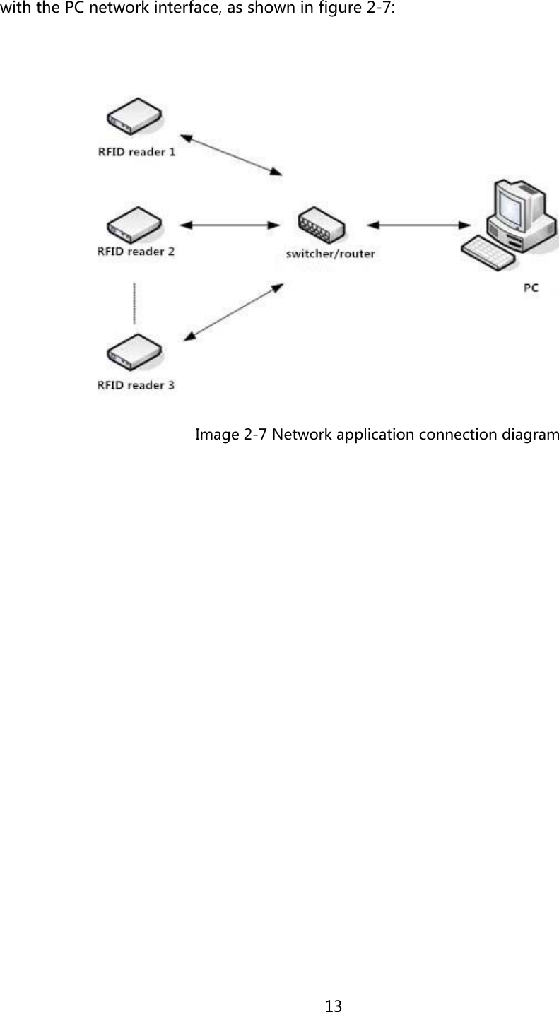
Clou IOT Technologies CLOUIOTCL7206C RFID Reader User Manual
Shenzhen Clou IOT Technologies Co.,Ltd. RFID Reader
UserManual.wiki
>
Clou IOT Technologies
>
CLOUIOTCL7206C User Manual
User Manual
Navigation menu
Upload a User Manual
Namespaces
Wiki Guide
HTML
PDF
Info
Views
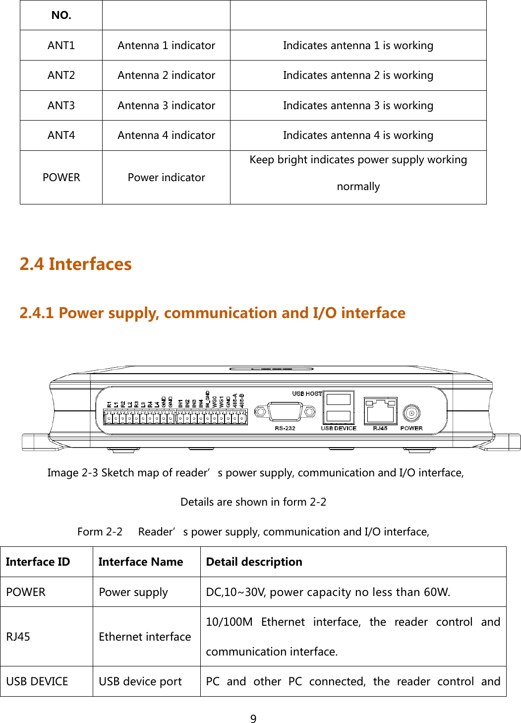
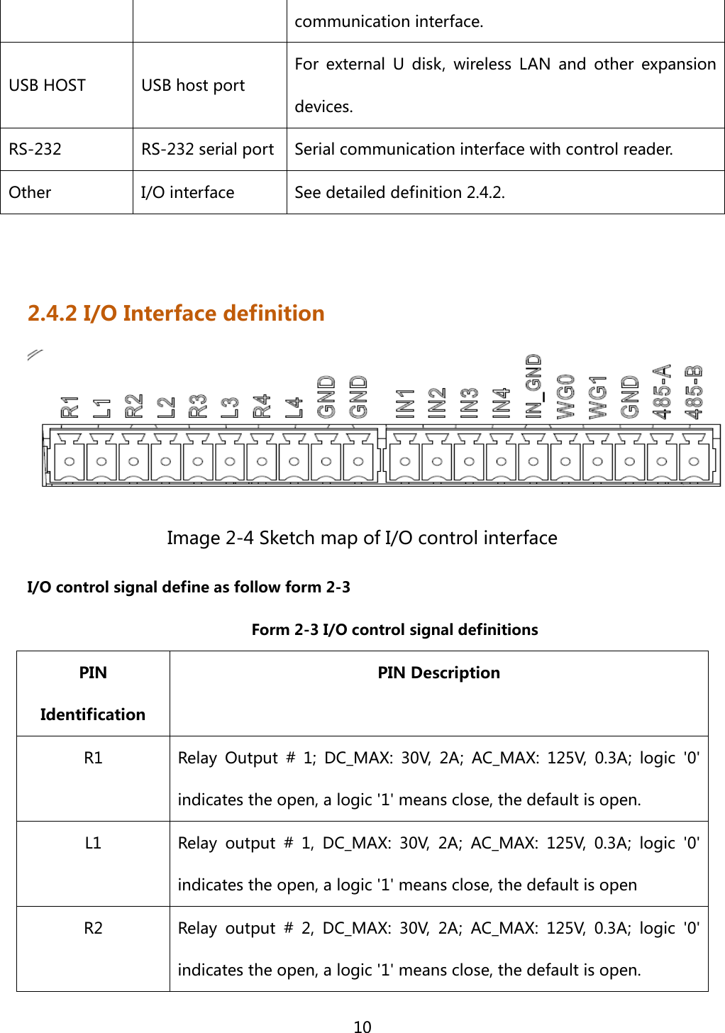
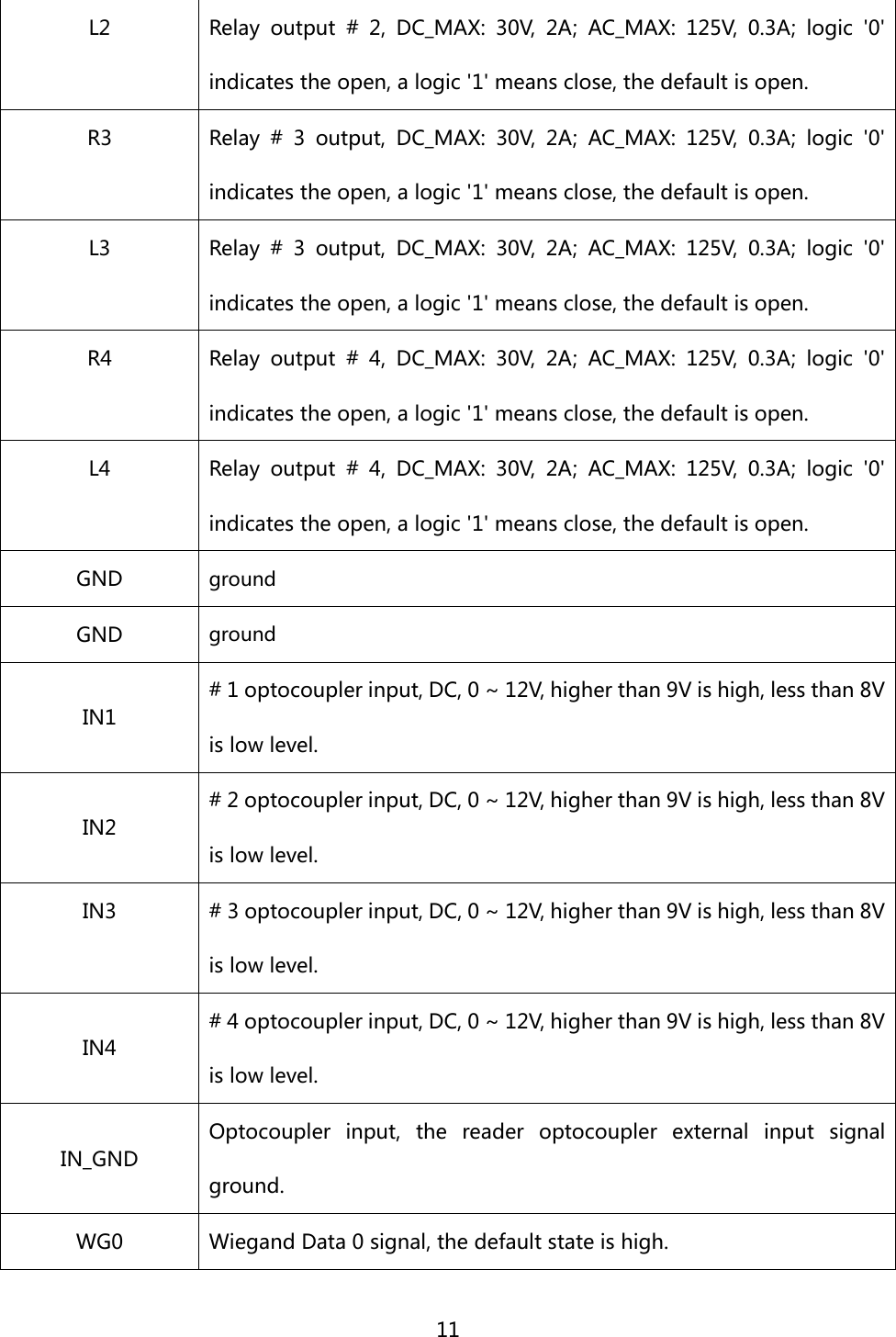
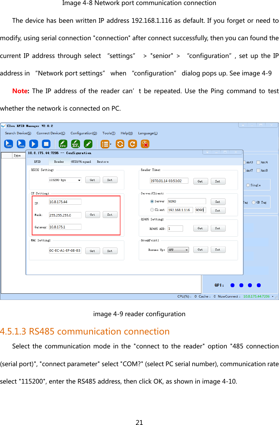
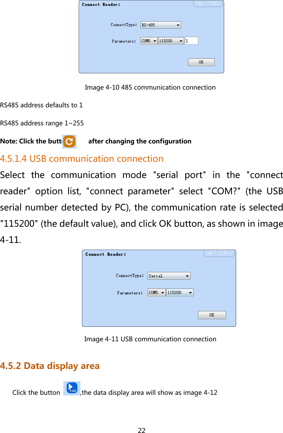
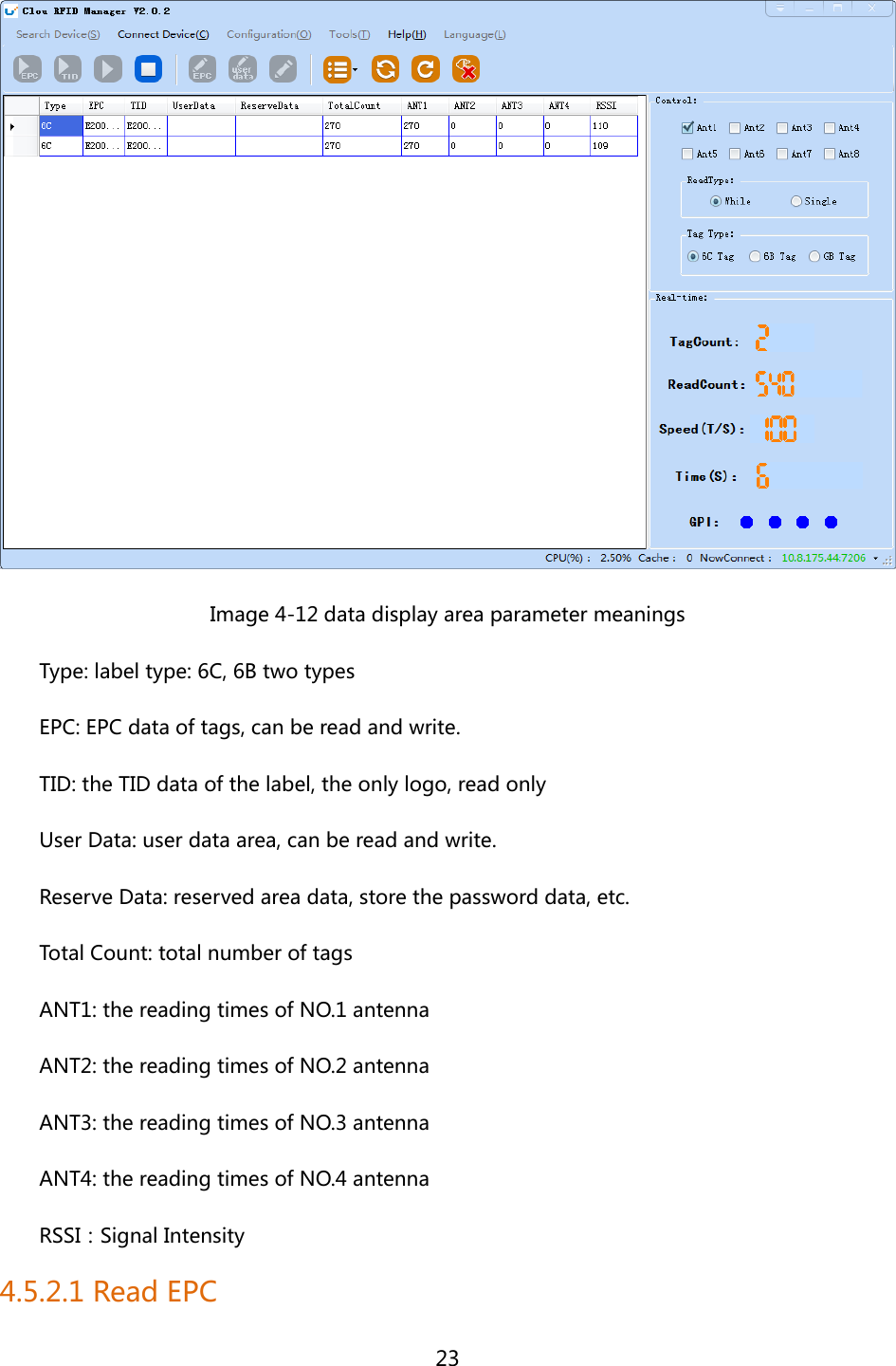
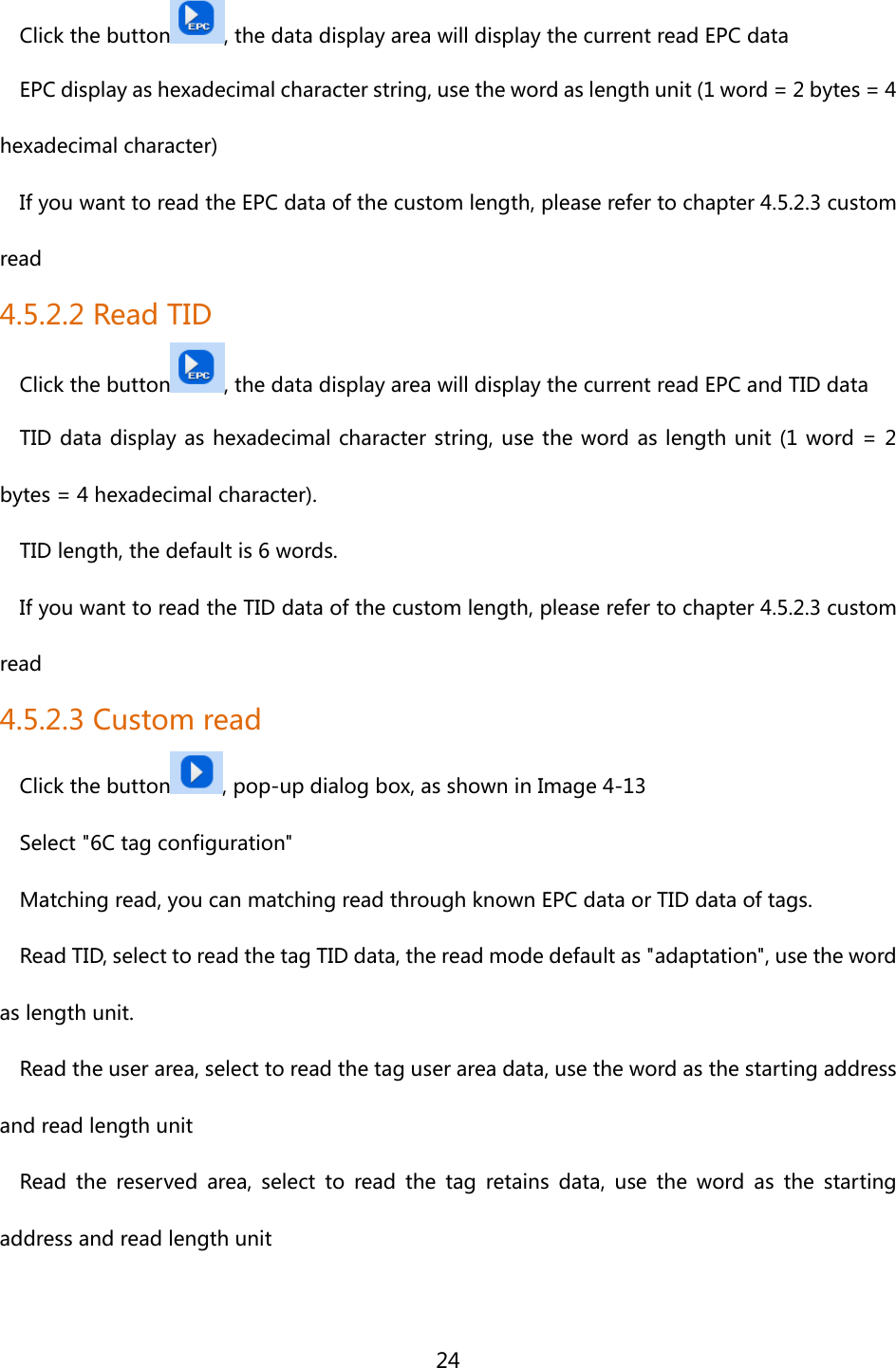
User Manual
Discussion / Help
Navigation