Cobra Electronics 29BT2K9 BLUETOOTH ACCESSORY FOR CB RADIO User Manual 29WXNWBT MANL qx
Cobra Electronics Corporation BLUETOOTH ACCESSORY FOR CB RADIO 29WXNWBT MANL qx
UserManual.wiki
>
Cobra Electronics
>
29BT2K9 User Manual
Users Manual
Navigation menu
Upload a User Manual
Namespaces
Wiki Guide
HTML
PDF
Info
Views
User Manual
Discussion / Help
Navigation
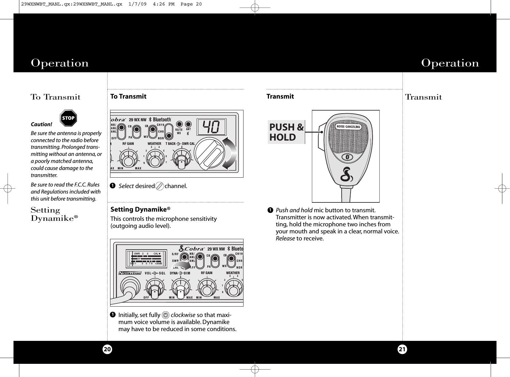
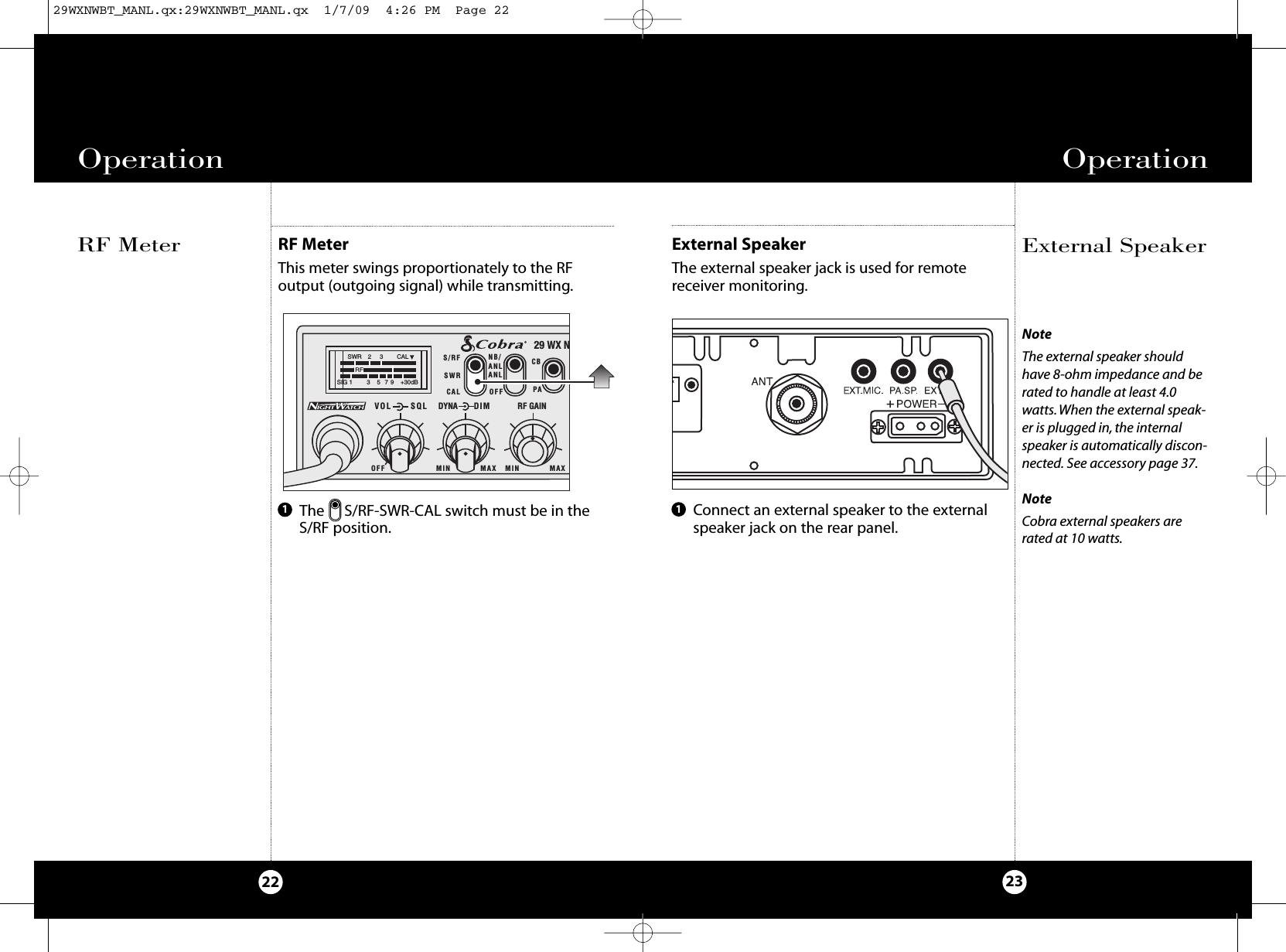
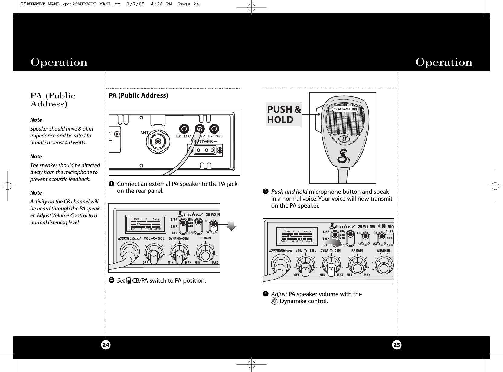
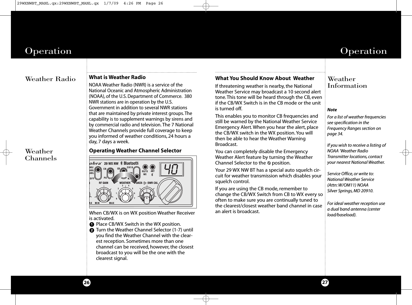
![3938Optional AccessoriesOrdering From U.S.A.Call 773-889-3087 for pricing or visit www.cobra.com.For Credit Card OrdersCall 773-889-3087 [Press one from the main menu] 8:00 a.m. to 5:30 p.m. Central Time, Monday through Friday.Make Check or Money Order Payable ToCobra Electronics, Attn: Accessories Dept., 6500 West Cortland Street, Chicago, IL 60707 U.S.A.To Order OnlinePlease visit our website: www.cobra.comNotes29WXNWBT_MANL.qx:29WXNWBT_MANL.qx 1/7/09 4:26 PM Page 38](https://usermanual.wiki/Cobra-Electronics/29BT2K9/User-Guide-1092368-Page-20.png)