Cobra Electronics MRF77 VHF Marine Radio User Manual MRF77W B GPS MANL v C
Cobra Electronics Corporation VHF Marine Radio MRF77W B GPS MANL v C
Contents
- 1. User Manual I Part 1
- 2. User Manual I Part 2
- 3. User Manual II Part 1
- 4. User Manual II Part 2
User Manual II Part 1
Owner’s Manual
Nothing Comes Close to a Cobra® English
Class-D Fixed Mount VHF Radio
MR F77W GPS
MR F77B GPS
Printed in China Part No. 480-1016-P Version C
®
®
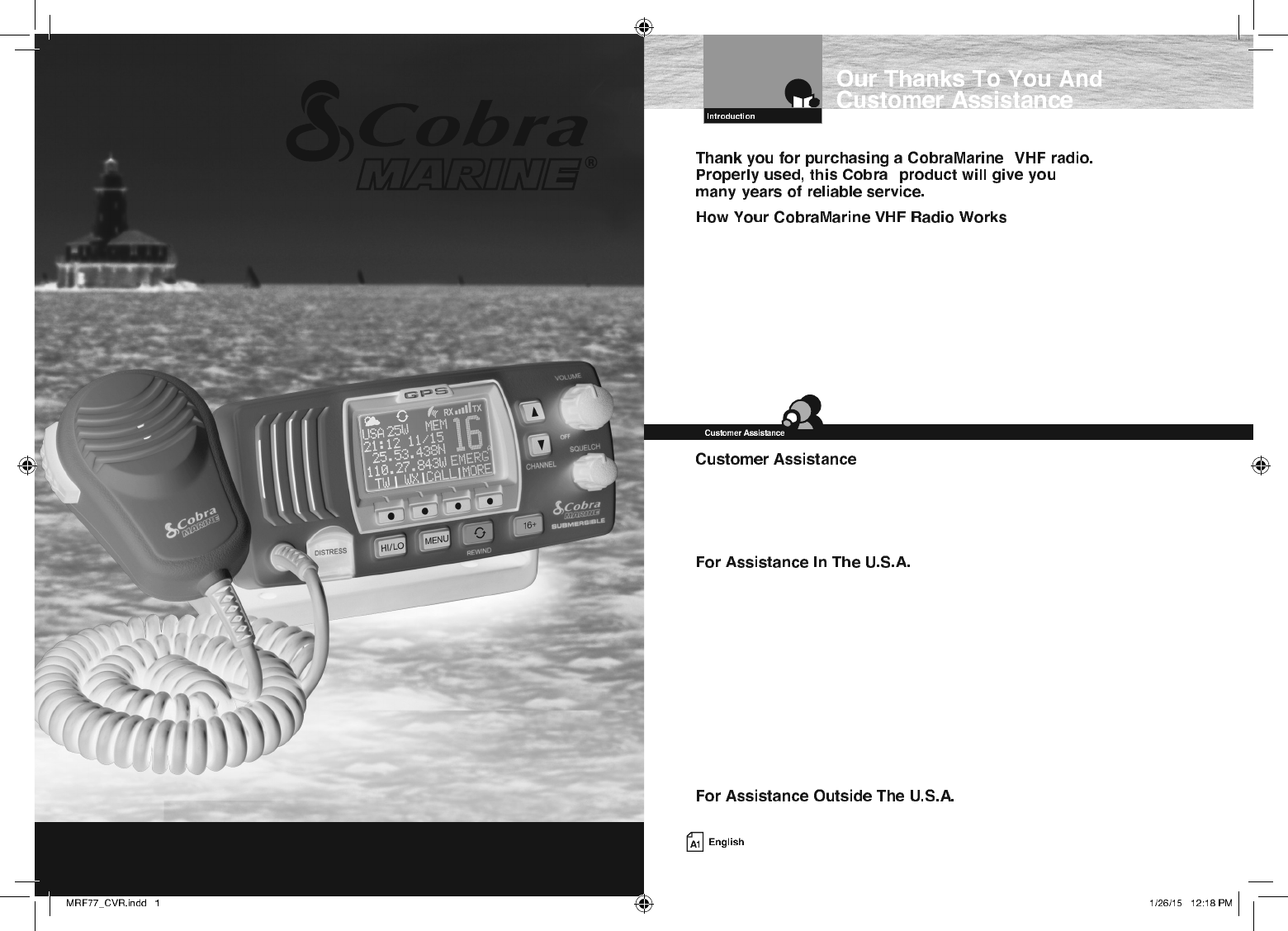
This radio is a VHF transceiver for xed mounting on your boat. It gives you 2-way
vessel-to-vessel and vessel-to-shore station communications, primarily for safety and
secondarily for navigation and operational purposes. With it, you can call for help, get
information from other boaters, talk to lock or bridge tenders and make radiotelephone
calls to anywhere in the world through a marine operator.
Besides 2-way communications, in the U.S.A., the radio can provide quick
access to receive eight NOAA (National Oceanographic and Atmospheric
Administration) and two Canadian weather channels for alerting you to weather
emergencies with a tone on a weather channel you can select for your area.
Should you encounter any problems with this product, or not understand
its many features, please refer to this owner’s manual. If you require further
assistance after reading this manual, Cobra Electronics offers the following
customer assistance services:
Automated Help Desk English only.
24 hours a day, 7 days a week 773-889-3087 (phone).
Customer Assistance Operators English and Spanish.
8:00 a.m. to 5:30 p.m. Central Time Mon. through Fri. (except holidays)
773-889-3087 (phone).
Questions English and Spanish.
Faxes can be received at 773-622-2269 (fax).
Technical Assistance English only.
www.cobra.com (on-line: Frequently Asked Questions).
English and Spanish. productinfo@cobra.com (e-mail).
Contact Your Local Dealer ©2015 Cobra Electronics Corporation
6500 West Cortland Street
Chicago, Illinois 60707 USA
www.cobra.com
Built-In GPS Receiver
Shows GPS coordinates on screen and
automatically sends GPS location with
DSC calls.
Rewind-Say-Again®
Replay missed VHD calls. Automatically
records the last 20 seconds of incoming
radio transmissions. Great when in noisy
conditions.
Dual Power
Selectable to one (1) or 25 watts output
power for near or distant calling.
USA/International/Canada Channels
Allows operation on any of the three (3)
different channel maps established for
these areas.
All NOAA Weather Channels
Instant access to all of the National
Weather Channels, 24 hours a day.
Emergency Weather Alert
Can alert you with an audible tone and visual
alarm if threatening weather is nearby.
Instant Channel 16/9
Instant access to the priority
Channel 16 and calling Channel 9.
Digital Selective Calling (DSC Class-D)
Allows the ability to maintain a listening
watch on VHF Channel 16 while
simultaneously monitoring Channel 70
for DSC calls. Allows sending a distress
message at the touch of a button as well as
specific station-to-station calls. Radio utilizes
two (2) built-in encoders (receivers).
Memory Scan
Lets you scan through all selected memory
channels to find conversations in progress.
Tri-Watch
Lets you monitor three (3) channels
at once — Channel 16, Channel 9,
and one (1) user selectable channel.
Noise Canceling Microphone
Blocks background noise to let your
voice be heard at the receiving station.
Illuminated Buttons
Helps you quickly find the buttons
you need in low light conditions.
Mounting Kits Included
Radio can be mounted on, under, or in
almost any flat surface using one (1) of
the included brackets.
Waterproof
Submersible to (1.5) meters of water for
30 minutes - meets IPX8/JIS8 Standards.
Alarm In
Allows connection to the alarm output of
your chart plotter to alert you when an
arrival, off-course, etc. alarm has been
activated.
Product Features
Introduction
Our Thanks To You . . . . . . . . . . . . . . . . . . . . . . . . . . . . . . . . . . . . . . . . . . . . . . . . . . . . . . A1
Customer Assistance . . . . . . . . . . . . . . . . . . . . . . . . . . . . . . . . . . . . . . . . . . . . . . . . . . . . . A1
Transceiver Controls, Indicators And Connections . . . . . . . . . . . . . . . . . . . . . . . . . . . . . . A2
Product Features . . . . . . . . . . . . . . . . . . . . . . . . . . . . . . . . . . . . . . . . . . . . . . . . . . . . . . . . A3
Important Safety Information . . . . . . . . . . . . . . . . . . . . . . . . . . . . . . . . . . . . . . . . . . . . . . . 2
Recommendations For Marine Communication . . . . . . . . . . . . . . . . . . . . . . . . . . . . . . . . . 4
VHF Marine Radio Protocols
FCC Licensing Information . . . . . . . . . . . . . . . . . . . . . . . . . . . . . . . . . . . . . . . . . . . . . . . . . 5
VHF Marine Radio Procedures . . . . . . . . . . . . . . . . . . . . . . . . . . . . . . . . . . . . . . . . . . . . . . . 6
Voice Calling . . . . . . . . . . . . . . . . . . . . . . . . . . . . . . . . . . . . . . . . . . . . . . . . . . . . . . . . . . . . 7
Digital Selective Calling (DSC) . . . . . . . . . . . . . . . . . . . . . . . . . . . . . . . . . . . . . . . . . . . . . . . 8
Maritime Mobile Service Identity (MMSI) . . . . . . . . . . . . . . . . . . . . . . . . . . . . . . . . . . . . . . 9
Radiotelephone Calls . . . . . . . . . . . . . . . . . . . . . . . . . . . . . . . . . . . . . . . . . . . . . . . . . . . . . 10
Emergency Messages And Distress Procedure . . . . . . . . . . . . . . . . . . . . . . . . . . . . . . . . . 10
Marine Distress Procedure – DSC . . . . . . . . . . . . . . . . . . . . . . . . . . . . . . . . . . . . . . . . . . . 13
Installation and Start-Up
Included In This Package . . . . . . . . . . . . . . . . . . . . . . . . . . . . . . . . . . . . . . . . . . . . . . . . . 14
Accessories Order Info . . . . . . . . . . . . . . . . . . . . . . . . . . . . . . . . . . . . . . . . . . . . . . . . . . . 15
Mounting and Powering The Radio . . . . . . . . . . . . . . . . . . . . . . . . . . . . . . . . . . . . . . . . . . 16
Antenna Requirements And Attachment . . . . . . . . . . . . . . . . . . . . . . . . . . . . . . . . . . . . . . 20
External Devices And Connections . . . . . . . . . . . . . . . . . . . . . . . . . . . . . . . . . . . . . . . . . . 22
Operating Your Radio
Getting Started . . . . . . . . . . . . . . . . . . . . . . . . . . . . . . . . . . . . . . . . . . . . . . . . . . . . . . . . . 24
Set-Up Routines. . . . . . . . . . . . . . . . . . . . . . . . . . . . . . . . . . . . . . . . . . . . . . . . . . . . . . . . . 28
Voice Transmission . . . . . . . . . . . . . . . . . . . . . . . . . . . . . . . . . . . . . . . . . . . . . . . . . . . . . . 32
NOAA All Hazards/Weather Radio And Alert . . . . . . . . . . . . . . . . . . . . . . . . . . . . . . . . . . . 33
GPS Menu . . . . . . . . . . . . . . . . . . . . . . . . . . . . . . . . . . . . . . . . . . . . . . . . . . . . . . . . . . . . . 33
Digital Select Calling (DSC) Set-Up . . . . . . . . . . . . . . . . . . . . . . . . . . . . . . . . . . . . . . . . . . 38
Advanced Operation . . . . . . . . . . . . . . . . . . . . . . . . . . . . . . . . . . . . . . . . . . . . . . . . . . . . . 44
Digital Select Calling (DSC) Operation . . . . . . . . . . . . . . . . . . . . . . . . . . . . . . . . . . . . . . . . 50
Maintenance and Troubleshooting . . . . . . . . . . . . . . . . . . . . . . . . . . . . . . . . . . . . . . . . . . 64
Specifications . . . . . . . . . . . . . . . . . . . . . . . . . . . . . . . . . . . . . . . . . . . . . . . . . . . . . . . . . . 65
Appendix
VHF Marine Channel Assignments . . . . . . . . . . . . . . . . . . . . . . . . . . . . . . . . . . . . . . . . . . 66
NOAA Weather Channels And Alert . . . . . . . . . . . . . . . . . . . . . . . . . . . . . . . . . . . . . . . . . . 81
World City Time Zones. . . . . . . . . . . . . . . . . . . . . . . . . . . . . . . . . . . . . . . . . . . . . . . . . . . . 82
Warranty
Limited 3-Year Warranty . . . . . . . . . . . . . . . . . . . . . . . . . . . . . . . . . . . . . . . . . . . . . . . . . . 83
Customer Service
Product Service . . . . . . . . . . . . . . . . . . . . . . . . . . . . . . . . . . . . . . . . . . . . . . . . . . . . . . . . . 84
Flush Mount Template . . . . . . . . . . . . . . . . . . . . . . . . . . . . . . . . . . . . . . . . . . . . . . . . . . . . 85
Important Safety Information
Before installing and using your CobraMarine VHF radio, please read these general
precautions and warnings.
To make the most of this radio, it must be installed and used properly.
Please read the installation and operating instructions carefully before installing and
using it. Special attention must be paid to the WARNING and NOTICE statements in
this manual.
WARNING
Statements identify conditions that could result in personal injury or loss of life.
NOTICE
Statements identify conditions that could cause damage to the radio
or other equipment.
This CobraMarine radio is designed for and classified as “Occupational Use Only.”
It must only be used in the course of employment by individuals aware of both the
hazards and the ways to minimize those hazards. This radio is NOT intended for
use in an uncontrolled environment by the “General Population.”
Q FCC OET Bulletin 65 Edition 97-01 Supplement C, Evaluating Compliance with FCC
Guidelines for Human Exposure to Radio Frequency Electromagnetic Fields.
Q American National Standards Institute (C95.1-1992), IEEE Standard for Safety
Levels with Respect to Human Exposure to Radio Frequency Electromagnetic
Fields, 3 kHz to 300 GHz.
Q American National Standards Institute (C95.3-1992), IEEE Recommended Practice
for the Measurement of Potentially Hazardous Electromagnetic Fields — RF and
Microwave.
Q Cobra Electronics Corporation™ recommendations for radio frequency exposure
are based upon the federal regulatory requirements in the U.S.A. Your country
may have different requirements. Ask your dealer or another knowledgeable
person. Compliance with recommendations for Radio Frequency Exposure is the
responsibility of both the antenna installer and the radio operator.
The following WARNINGS and NOTICES will make you aware of RF exposure hazards
and how to assure you operate the radio within the FCC RF exposure
limits established for it.
WARNINGS
Your radio generates electromagnetic RF (radio frequency) energy when it
is transmitting. To ensure that you and those around you are not exposed
to excessive amounts of that energy, DO NOT touch the antenna when
transmitting. KEEP the radio at least two (2) inches (5 cm) away from yourself
and others when transmitting. SEE page 20 in the antenna requirements
section for further information.
DO NOT operate the radio without a proper antenna or equivalent dummy load
attached. Doing so may expose you to excessive RF energy and will damage
the radio.
DO NOT transmit more than 50% of the time the radio is in use — 50% duty
cycle. The radio is transmitting when the Talk button is pressed and the
transmit information shows on the LCD screen.
ALWAYS use only Cobra authorized accessories.
NEVER connect the transceiver to AC power. It can be a fire hazard, may cause
an electric shock, and may damage the transceiver.
NEVER mount the transceiver or microphone where they might interfere with
operation of your vessel or cause injury.
DO NOT allow children or anyone unfamiliar with proper procedures to operate
the radio without supervision.
Failure to observe any of these warnings may cause you to exceed
FCC, Industry Canada or EU RF exposure limits or create other dangerous
conditions.
NOTE
Throughout this manual, the term “Transceiver” will be used to identify the main
unit containing the LCD screen and controls. The term “Radio” will be used to
identify the entire equipment including transceiver, microphone, antenna and any
attached external speakers.
NOTICES
AVOID using or storing the radio at temperatures below -4°F (-20°C) or above
140°F (55°C).
NEVER connect the transceiver to DC power greater than 16 volts or to
any DC source with reversed polarity. Doing so will damage the transceiver.
DO NOT cut the power cables attached to the transceiver. Improper
reconnection with reversed polarity will damage the transceiver.
POSITION your radio, external speakers, and cables at least three (3) feet (0.9 m)
away from your vessel’s magnetic navigation compass. CHECK your compass
before and after installation to be sure that it has not introduced any deviation.
DO NOT attempt to service any internal parts yourself. Have any
necessary service performed by a qualified technician.
DO NOT drop the transceiver or microphone. Doing so may crack the
case or damage a waterproof seal. Once these items have been dropped,
the original waterproofing cannot be guaranteed.
DO NOT use chemicals or solvents such as mineral spirits and alcohol
to clean your radio. They may damage the case surfaces.
Changes or modifications to your radio MAY VOID its compliance with FCC (Federal
Communications Commission) rules and make it illegal to use.
Recommendations For Marine Communication
The frequencies your radio uses are set aside to enhance safety afloat and for
vessel navigation and operational messages over a range suitable for nearshore
voyages. If the 25 watt maximum output of your radio isn’t sufficient for the distances
you travel from the coast, consider installing more powerful radio equipment such as
HF single side band or satellite radio for your vessel.
The U.S. Coast Guard does not endorse cellular telephones as substitutes for
marine radios. They generally cannot communicate with rescue vessels and,
if you make a distress call on a cellular telephone, only the party you call will
be able to hear you. Additionally, cellular telephones may have limited coverage
over water and can be hard to locate. If you don’t know where you are, the
Coast Guard will have difficulty finding you if you’re using a cellular telephone.
However, cellular telephones can have a place on board where cellular coverage
is available — to allow social conversations and keep the marine frequencies
uncluttered and available for their intended uses.
Sea Tow Automated Radio Check (ARC) System
Please try the Sea Tow Automated Radio Check service. Areas where the safety check
service is available include the East Coast, Gulf of Mexico, Southern California, and select
inland locations including the Great Lakes. The first and only boating safety program of its
kind, the Sea Tow Automated Radio Check service is fully automated and allows 24 hour a
day automated responses to radio check calls.
Conducting a radio check through the Sea Tow Automated Radio Check service couldn’t
be simpler. All boaters need to do is tune their VHF radio to Channel 24, 25, 26, 27, 28 or
84 (channel varies by location), then key the mic and ask for a radio check. The system
responds to each radio check with an automated reply including the location, and also
replays the boater’s original radio transmission, allowing them to assess the strength of the
signal and confirm the VHF radio is in good working order.
To find the Sea Tow Automated Radio Check service channel in an area boaters, radio
owners should visit www.seatow.com/arc. The web page allows you to search for the local
channel and has an instructional video on how to use the service step by step.
FCC LICENSING INFORMATION
CobraMarine VHF radios comply with the FCC (Federal Communication Commission)
requirements that regulate the Maritime Radio Service.
This CobraMarine radio incorporates a VHF FM transceiver designed for use in
the frequency range of 156.025 to 163.275 MHz. It requires 13.8 volts DC and
has a switchable RF output power of one (1) or 25 watts.
The transceiver is capable of Class-D (Digital Selective Calling) operation in accordance with
CFR Part 47, Section 80,225.
The radio operates on all currently allocated marine channels and is switchable for use
according to U.S.A., International, or Canadian regulations. It features instant access to
emergency Channel 16 and calling Channel 9 as well as NOAA (National Oceanic and
Atmospheric Administration) All Hazards Radio with Alert that can be accessed by pressing
one (1) key.
An FCC ship station license is no longer required for any vessel traveling in U.S.A. waters
which uses a VHF marine radio, RADAR, or EPIRB (Emergency Position Indicating Radio
Beacon), and which is not required to carry radio equipment. However, any vessel
required to carry a marine radio on an international voyage, carrying a HF single side band
radiotelephone, or carrying a marine satellite terminal must obtain a station license.
FCC license forms and applications for ship and land stations can be downloaded through
the Internet at www.fcc.gov/forms. Forms can also be obtained by calling the FCC at 888-
225-5322.
If your vessel will be entering the sovereign waters of a country other than the U.S.A. or
Canada, you should contact that country’s communications regulatory authority for licensing
information.
Currently, the FCC does not require recreational boaters to have a license. The United States
Coast Guard recommends that the boat’s registration number and state of registry (e.g., IL 1234
AB) be used as a call sign and be clearly visible on the vessel.
You need a Radio Operator’s Certificate if your vessel is operated in Canadian waters. Radio
Operator training and certification is available from the Canadian Power Squadron. Visit their
website (http://www.cps-ecp.ca/english/newradiocard.html), contact the nearest field office
or write: Industry of Canada, Radio Regulatory Branch, Attn: DOSP, 300 Slater Street, Ottawa,
Ontario, Canada K1A 0C8.
All users are responsible for observing domestic and foreign government regulations
and are subject to severe penalties for violations. The VHF frequencies on your radio are
reserved for marine use and require a special license to operate from land, including when
your boat is on its trailer.
NOTE
This device complies with part 15 of the FCC Rules. Operation is
subject to the following two (2) conditions: (1) This device may not cause
harmful interference, and (2) This device must accept any interference
received, including interference that may cause undesired operation.
FCC Warnings: Replacement or substitution of transistors, regular diodes,
or other parts of a unique nature, with parts other than those recommended
by Cobra® may cause a violation of the technical regulations of part 80 of the
FCC Rules, or violation of type acceptance requirements of part 2 of the rules.
VHF Marine Radio Procedures
Whenever your boat is underway, the radio must be turned On and be tuned to Channel 16,
except when being used for messages.
Try 1 watt first if the station being called is within a few miles. Try a second call after
waiting two (2) minutes. If there is no answer, switch to a higher power. This will conserve
your battery and minimize interference to other users by avoiding repeated calls.
Call a coast station on its assigned channel. You may use Channel 16 when you do not
know the assigned channel.
Call other vessels on Channel 16 or on Channel 9. (Channel 9 is preferred
for recreational vessel use.) You may also call on ship-to-ship channels
when you know that the vessel is listening on a ship-to-ship channel.
The use of Channel 16 is permitted for making initial contact (hailing) with another vessel.
The limits on calling must be followed. Be reminded, Channel 16’s most important function
is for Emergency Messages. If, for some reason, Channel 16 is congested, the use of
Channel 9, especially in U.S. waters, may be used as the initial contact (hailing) channel for
non-emergency communication.
You must not call the same station for more than 30 seconds at a time.
If you do not get a reply, wait at least two (2) minutes before calling again.
After three (3) calling periods, wait at least 15 minutes before calling again.
After contacting another station on a calling channel, change immediately
to a channel which is available for the type of message you want to send.
Identify, in English, your station by your FCC call sign, ship name, the state registration
number, or other official number at both the beginning and end of each message.
You MUST NOT transmit:
Q False distress or emergency messages.
Q Messages containing obscene, indecent, or profane words or meaning.
Q General calls, signals, or messages (messages not addressed to a particular station) on
Channel 16, except in an emergency or if you are testing your radio.
Q When you are on land.
Voice Calling
To Call Another Vessel Or A Shore Installation Such As A Lock Or Bridge Tender:
Q Make sure your radio is On.
Q Select Channel 16 and listen to make sure it is not being used.
NOTE
Channel 9 may be used by recreational vessels for general-purpose
calling. This frequency should be used whenever possible to relieve
congestion on Channel 16.
Q When the channel is quiet, press the Talk button and call the ship you wish
to call. (Hold the microphone a few inches from your face and speak directly into it in a
normal tone of voice — clearly and distinctly.) Say “[name
of station being called] THIS IS [your vessel’s name or call sign].”
Q Once contact is made on the calling channel, you must switch to a proper working
channel. See the channel listing on page 66 through 78.
The vessel Corsair calling the vessel Vagabond:
Corsair: “Vagabond, this is Corsair (station license number call sign).”
Vagabond: “Corsair, this is Vagabond. Over.”
Corsair: “Vagabond go to working Channel 68. Over.”
Both parties switch over to the agreed upon working channel....
Corsair: “Vagabond I need to talk to you about... Over.”
Vagabond: “Corsair in answer to your question about... Over.”
Corsair: “Vagabond, thanks for the information about... (call sign and out).”
After each transmission, say “OVER” and release the microphone Push to Talk (PTT)
button. This confirms that the transmission has ended. When all communication with
the other vessel is totally completed, end the message by stating your call sign and
the word “OUT.” Remember, it is not necessary to state your call sign with each
transmission, only at the beginning and end of the message.
NOTE
For best sound quality at the shore station or other vessel receiving your call, hold
the microphone/speaker at least 2 in. (51 mm) from your mouth and
slightly off to one (1) side. Speak in a normal tone of voice.
Digital Selective Calling (DSC)
Digital selective calling is a semi-automated system for establishing a radio
call. It has been designed by the International Maritime Organization (IMO)
as an international standard for VHF, MF, and HF calls and is part of the
Global Maritime Distress and Safety System (GMDSS).
DSC will eventually replace aural (listening) watches on distress frequencies
and will be used to announce routine and urgent maritime safety information
broadcasts. Until DSC is fully implemented, it is still necessary to maintain a listening
watch on Channel 16.
The DSC system allows mariners to instantly send a distress call with GPS
position coordinates (requires a GPS receiver to be connected to the radio)
to the Coast Guard and other vessels within range of the transmission.
DSC also allows mariners to initiate and receive distress, urgent, safety,
routine, position request, position send, and group calls between vessels
equipped with DSC capable radios.
Maritime Mobile Service Identity (MMSI)
The MMSI Number Is Available In The U.S.A. From Any Of Two (2) Sources:
Q U.S. Power Squadron www.usps.org
Q BoatU.S.: 1-800-563-1536 – www.boatus.com/mmsi
NOTE
The above references are for recreational vessels only. Commercial vessels
should contact the FCC.
An MMSI is a nine (9) digit number used on a marine radio capable of using digital
selective calling (DSC). It is used to selectively call other vessels or shore stations and
is similar to a telephone number.
For your CobraMarine™ radio to operate in the DSC mode, you must enter your
maritime mobile service identity (MMSI) number. See page 41 for instructions
on how to enter it.
In Canada, Contact:
Q Industry Canada Spectrum Management Office (only available on the Internet):
www.ic.gc.ca and search for “MMSI”.
To Obtain An MMSI Number Outside The U.S.A.:
Users can obtain an MMSI from their country’s telecommunications authority
or ship registry. This may involve amending or obtaining a ship station license.
WARNING
This equipment is designed to generate a digital maritime distress and
safety signal to facilitate search and rescue. To be effective as a safety
device, this equipment must be used only within communication range
of a shore-based VHF marine channel to distress and safety watch system.
The range of the signal may vary, but under normal conditions should be
approximately 20 nautical miles.
Emergency Messages And Distress Procedure
The ability to summon assistance in an emergency is the primary reason
to have a VHF marine radio. The marine environment can be unforgiving,
and what may initially be a minor problem can rapidly develop into a
situation beyond your control.
The Coast Guard monitors Channel 16, responds to all distress calls, and coordinates
all search and rescue efforts. Depending on the availability of
other capable vessels or commercial assistance operators in your vicinity,
Coast Guard or Coast Guard Auxiliary craft may be dispatched.
In any event, do communicate with the Coast Guard as soon as you experience
difficulties and before your situation becomes an emergency. Use the emergency
message procedures only after your situation has become grave or you are faced with
a sudden danger threatening life or property and requiring immediate help.
Use channel 16 to communicate your emergency message. Make sure you transmit on
high power. If you are merely out of gas, do not send an emergency message. Drop
your anchor and call a friend or marine to bring the fuel you need or to give you a tow.
The three (3) spoken international emergency signals are:
The distress signal MAYDAY is used to indicate that a station is threatened
by grave and imminent danger and requests immediate assistance.
The urgency signal PAN is used when the safety of the vessel or person
is in jeopardy. (This signal is properly pronounced pahn.)
The safety signal SECURITE is used for messages about the safety of navigation or
important weather warnings. (This signal is properly pronounced see-cure-it-tay.)
When using an international emergency signal, the appropriate
signal is to be spoken three (3) times prior to the message.
You must give any message beginning with one (1) of these signals priority
over any other messages. ALL stations MUST remain silent on Channel 16
for the duration of the emergency unless the message relates directly to
the emergency.
If you hear a distress message from a vessel, stand by your radio. If it is
not answered, YOU should answer. If the distressed vessel is not nearby,
wait a short time for others who may be closer to acknowledge. Even if
you cannot render direct assistance, you may be in a position to relay
the message.
Speak slowly — clearly — calmly.
1. Make sure your radio is On.
2. Select VHF Channel 16.
3. Press Talk button and say:
“MAYDAY — MAYDAY — MAYDAY.”
(Or “PAN — PAN — PAN,”
or “SECURITE — SECURITE — SECURITE.”)
4. Say:
“THIS IS [your vessel name or call sign].”
5.
Say:
“MAYDAY (or “PAN” or “SECURITE”)
[your vessel name or call sign].
6. Tell where you are:
(what navigational aids or landmarks are near).
7. State the nature of your distress.
8. State the kind of assistance needed.
9. Give number of persons aboard and conditions of any injured.
10. Estimate present seaworthiness of your vessel.
11. Briefly describe your vessel (length, type, color, hull).
12. Say:
“I WILL BE LISTENING ON CHANNEL 16.”
13. End message by saying:
“THIS IS [your vessel name or call sign] OVER.”
14. Release Talk button and listen. Someone should answer.
If not, repeat the call, beginning at item 3 above.
Keep the radio nearby. Even after your message has been received, the Coast Guard can
find you more quickly if you can transmit a signal for a rescue boat to hone in on.
“Mayday — Mayday — Mayday”
“This is Corsair — Corsair — Corsair” [or “Illinois 1234 AB” three (3) times]
“Mayday Corsair (or Illinois 1234 AB)”
“Navy Pier bears 220 degrees magnetic — distance five (5) miles”
“Struck submerged object and flooding — need pump and tow”
“Four adults, three children aboard — no one injured”
“Estimate we will remain afloat one-half (1⁄2) hour”
“Corsair (or Illinois 1234 AB) is 26 foot sloop with blue hull and tan deck house”
“I will be listening on Channel 16”
“This is Corsair (or Illinois 1234 AB)”
“Over”
It is a good idea to write out a script of the message form and post it where you
and others on your vessel can see it when an emergency message needs to be sent.
Marine Distress Procedure – DSC
Digital Selective Calling (DSC) is a semi-automated system that will allow you to press
the Distress button from any routine to make a distress call. When the distress button
is pressed, all other channels go to Standby mode and allow the digitally encoded
“pre-programmed” message to take precedence. Important information such as your
MMSI number, position and name will be transmitted on Channel 16. The distress
alarm will sound for two (2) minutes or until the alarm is cleared.
The DSC system allows you to choose a “pre-programmed” distress call such as:
“Man Overboard, Sinking, Collision.” There are many pre-programmed choices to
choose from. If a GPS is connected to your radio, your coordinates will also be sent to
the Coast Guard as well as to other vessels that are within range of the transmission.
DSC calling also allows the user to initiate and receive distress, urgent, safety,
routine, position request, position send and group calls between vessels equipped
with DSC capable radios.
WARNING
This radio will generate a digital maritime distress and safety signal to
help facilitate search and rescue. This radio must be used only within
communication range of a shore based VHF station with a distress and safety
watch system. The range of the signal may vary, however, under normal
conditions should be approximately 20 nautical miles.
Call 773-889-3087 for pricing or visit www.cobra.com.
For Credit Card Orders
Call 773-889-3087 [Press one from the main menu] 8:00 a.m. to 5:30 p.m. Central Time, Monday
through Friday.
Make Check or Money Order Payable To
Cobra Electronics, Attn: Accessories Dept.,
6500 West Cortland Street, Chicago, IL 60707 U.S.A.
To Order Online
Please visit our website: www.cobra.com
Optional Accessories
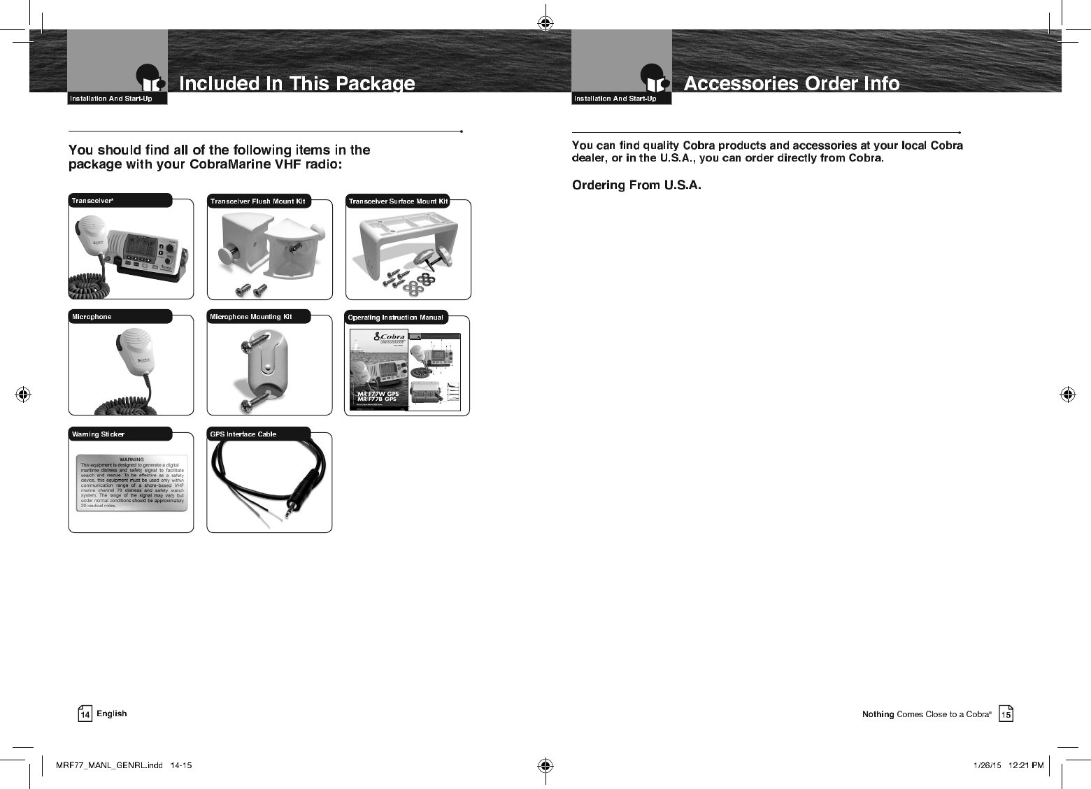
Included In This Package
A2 English
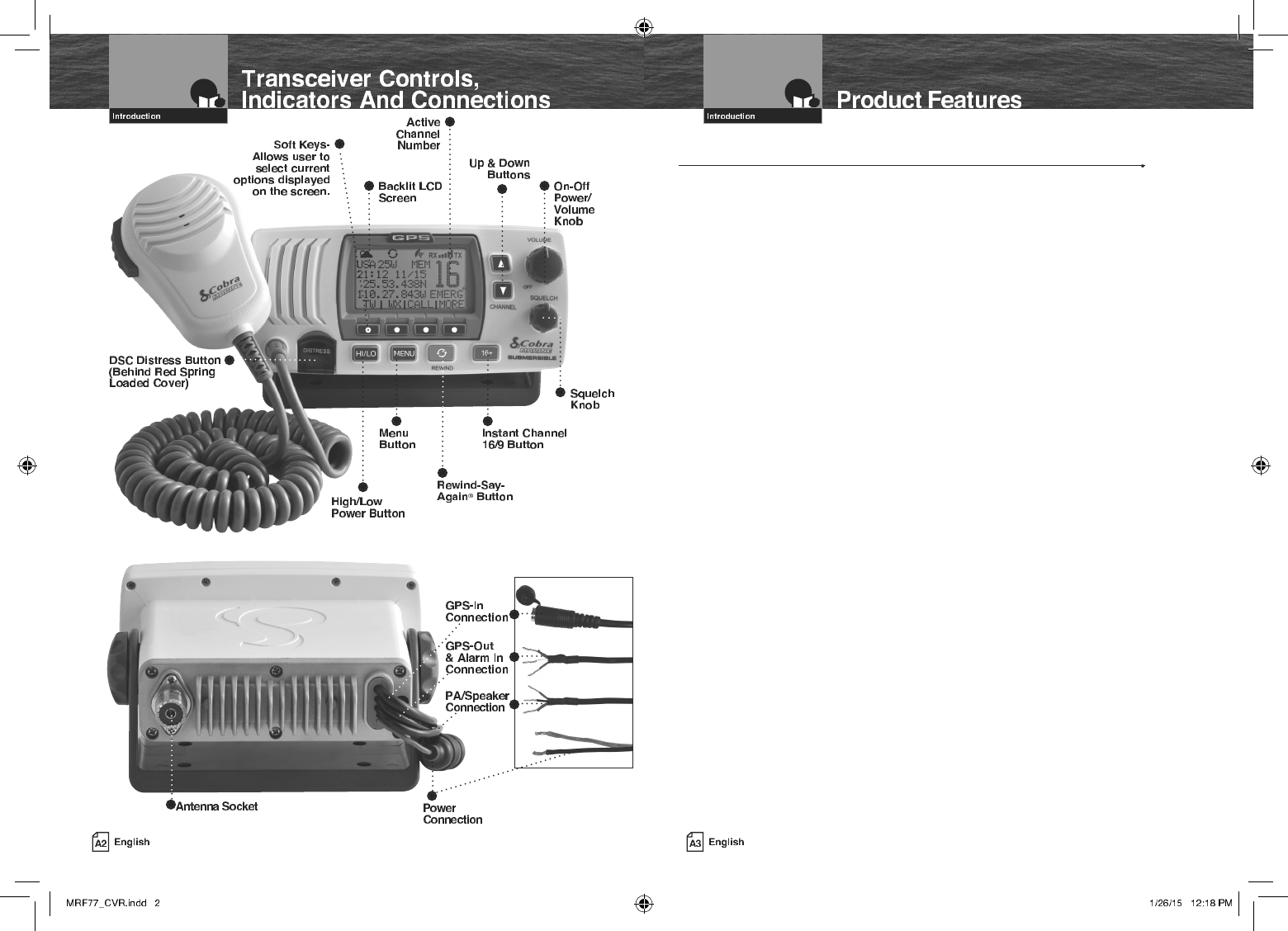
Transceiver Controls,
Indicators And Connections
Introduction
On-Off
Power/
Volume
Knob
Active
Channel
Number
Instant Channel
16/9 Button
Squelch
Knob
High/Low
Power Button
DSC Distress Button
(Behind Red Spring
Loaded Cover)
Soft Keys-
Allows user to
select current
options displayed
on the screen.
Power
Connection
Antenna Socket
Backlit LCD
Screen
Up & Down
Buttons
Menu
Button
Rewind-Say-
Again® Button
GPS-Out
Connection
PA/Speaker
Connection
GPS-In
Connection
Mounting And Powering The Radio
Before using your CobraMarine VHF radio, it must be installed on your vessel.
Choose a location for your radio where it will be conveniently accessible with the
following factors in mind:
Q The leads to the battery and the antenna are best kept as short as possible.
Q The antenna must be mounted at least three (3) feet from the transceiver.
Q The radio and all speakers need to be far enough from any magnetic
compass to avoid deviation due to the speaker magnet.
Q There needs to be free air flow around the heat-sink fins on the back
of the transceiver.
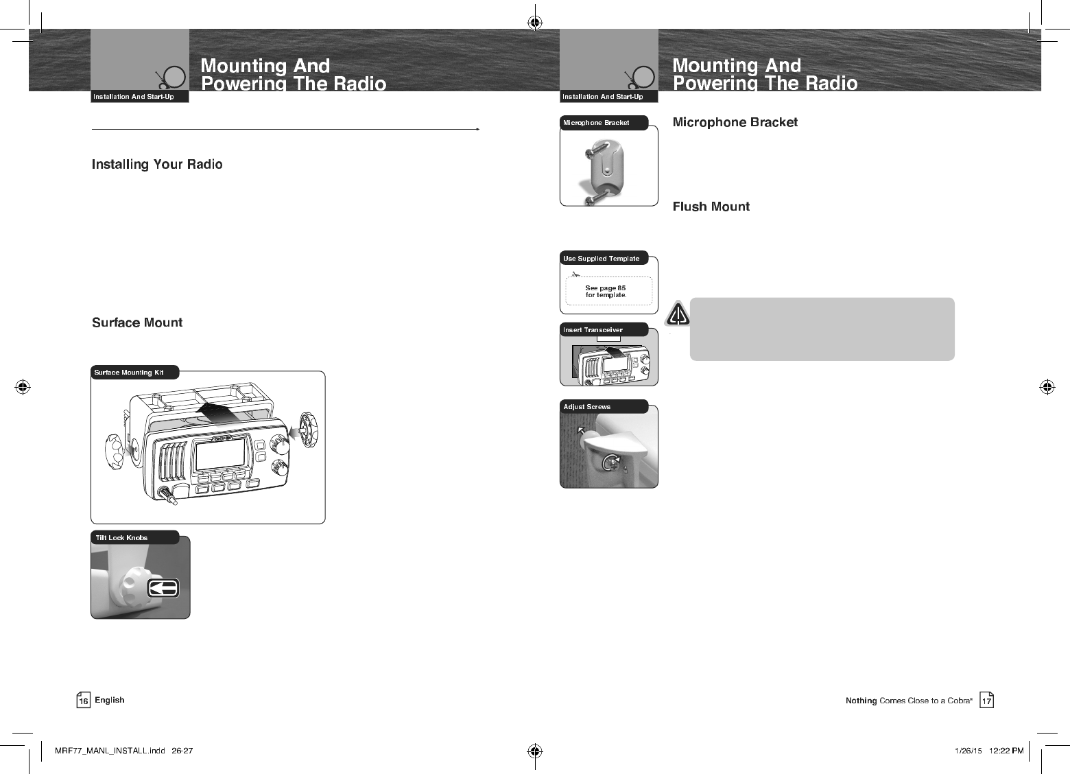
A Surface Mounting kit is included with your CobraMarine VHF radio to allow its
installation on almost any flat surface.
To Mount The Transceiver
On Almost Any Flat Surface:
1. Use the mounting bracket
as a template to drill holes
for the mounting screws.
2. Attach the mounting bracket
to the chosen surface.
3. Attach the transceiver to
the mounting bracket with
the locking knobs.
4. Tilt the transceiver to
a convenient angle and
tighten the locking knobs.
To Install The Microphone Bracket:
1. Install the microphone bracket
on a vertical surface near the transceiver
using the supplied stainless steel screws.
A Flush Mounting kit is included with your CobraMarine
VHF radio to allow its installation in almost any flat surface.
To Mount The Transceiver Flush In Almost Any Flat Surface:
1. Use the supplied template to mark and cut an opening
in the flat surface. See page 85 for template.
CAUTION
Before cutting, be sure the area behind the flat
surface is clear of any instruments or wires that
might be damaged in the process.
2. Insert the transceiver into the opening.
3. Attach the flush mounting brackets to the sides of the
transceiver with the adjusting screw flanges facing
the back of the flat surface.
4. Tighten the adjusting screws against the back of the flat
surface until the flange on the front of the transceiver
is tight against the flat surface.
NOTE
All wiring is best kept as short as possible. If the power leads must be
extended, use a high-quality, marine-grade cable sized for up to 10 amps
of current. To minimize voltage drop, choose a wire gauge as follows:
Length Wire Gauge
Up to 1.5m(4.9ft) 1.6 mils(#14)
Up to 3.0m(9.8 ft) 2.0 mils(#12)
Up to 5.0m(16.4 ft) 2.6 mils(#10)
Up to 6.0m(19.7 ft) 3.3 mils(#8)
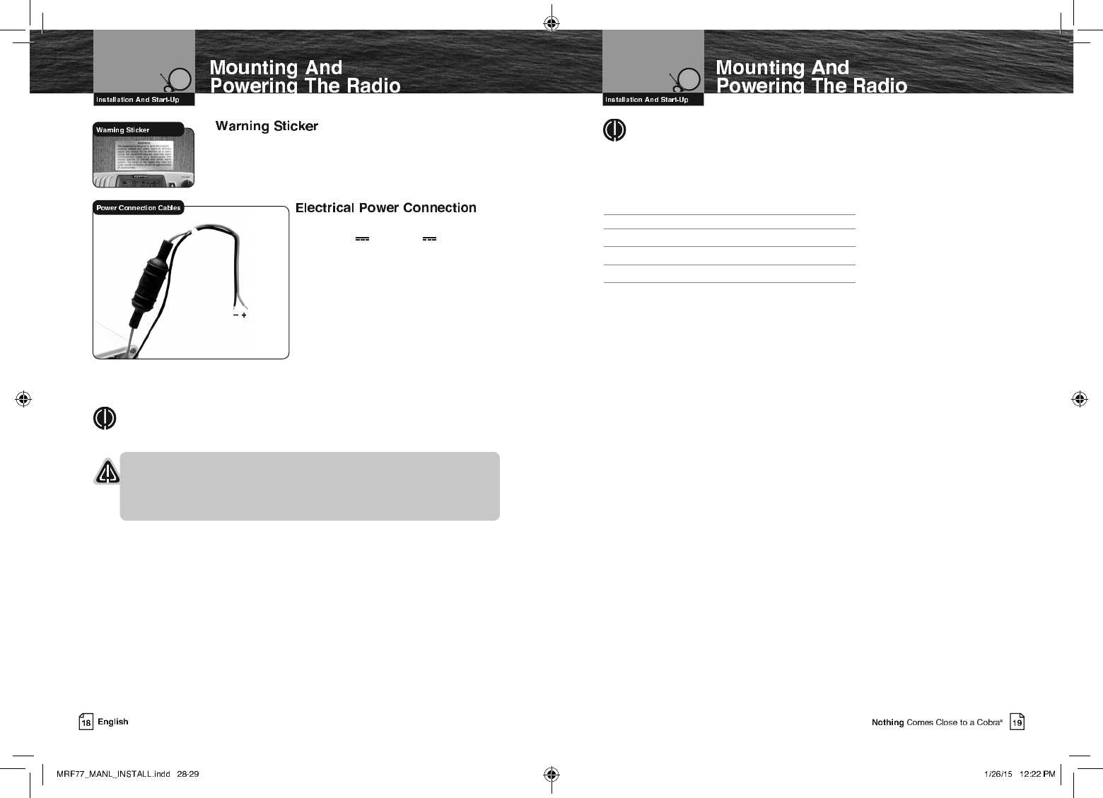
FCC regulations require that the Warning Sticker
supplied with this radio be applied to a spot where
it is easily seen by the radio operator. Be sure the
location is clean and dry before applying the sticker.
Your CobraMarine VHF radio is powered
from +10.0V to +16.0V vessel direct
current electrical, negative ground
systems (12-volt nominal). A fused
power connection lead is provided at the
back of the transceiver.
To Connect To A Power Source:
1. Attach the black (-) wire to a negative
(-) ground.
2. Attach the fused red power (+) wire
to the positive (+) side of the power
system.
NOTE
This radio will draw up to 8 amps when transmitting at full power.
NOTICES
A reverse polarity connection will damage the radio.
When replacing the fuse in your transceiver, use only the size and type
originally provided.
Red Cable
Positive (+)
Black Cable
Negative (-)
Antenna Requirements And Attachment
Your CobraMarine VHF radio requires an external marine antenna
to send signals into the air and to receive them. The radio is arranged
to use any of the popular marine VHF antennas, but it is up to you to
choose which antenna to use.
Since it represents the link between your radio and the outside world,
Cobra® suggests you purchase the best quality antenna, coaxial cable,
and connectors you can. This is best accomplished with the advice
and guidance of a knowledgeable dealer who can assess the variables
involved with your particular boat and preferences.
WARNING
Compliance with FCC requirements for Radio Frequency Exposure is
the responsibility of both the antenna installer and the radio operator.
Safe Maximum Permissible Exposure (MPE) Radius
To avoid health hazards from excessive exposure to RF energy, FCC OET Bulletin
65 establishes an MPE radius of 10’ (3 m) for the maximum power
of your radio with an antenna having a maximum power gain of 9 dBi.
This means that all persons must be at least 10’ (3 m) away from the
antenna when the radio is transmitting.
Installation Requirements
A) An omnidirectional antenna with a gain not greater than 9 dBi must
be mounted at least 16.4’ (5 m) above the highest deck where people
may be during radio transmissions, measured vertically from the lowest point
of the antenna. This provides the minimum separation distance
to comply with RF exposure requirements and is based on the MPE
radius of 10’ (3 m) plus the 6.6’ (2 m) height of an adult.
B) For vessels without structure to mount the antenna as described in A,
it must be mounted as follows AND all persons must be outside the
10’ (3 m) MPE radius during radio transmissions. The antenna must
be mounted so that its lowest point is at least 3.3’ (1 m) vertically above
the heads of all persons during radio transmissions.
Radio Operator Requirements
Do not transmit when anyone is within the MPE radius of the antenna unless
that person or persons are shielded from the antenna by a grounded metallic
barrier. This is especially important on vessels with antennas mounted as
described in B where no one may be within 9’ (2.8 m) horizontally from the base
of the antenna during transmissions.
FAILURE TO OBSERVE THE ABOVE LIMITS MAY EXPOSE THOSE WITHIN
THE MPE RADIUS TO RF ENERGY ABSORPTION IN EXCESS OF THE FCC
MAXIMUM PERMISSIBLE EXPOSURE. IT IS THE RADIO OPERATOR’S
RESPONSIBILITY TO INSURE THAT MPE LIMITS ARE HEEDED AND THAT
NO ONE IS WITHIN THE MPE RADIUS DURING TRANSMISSIONS.
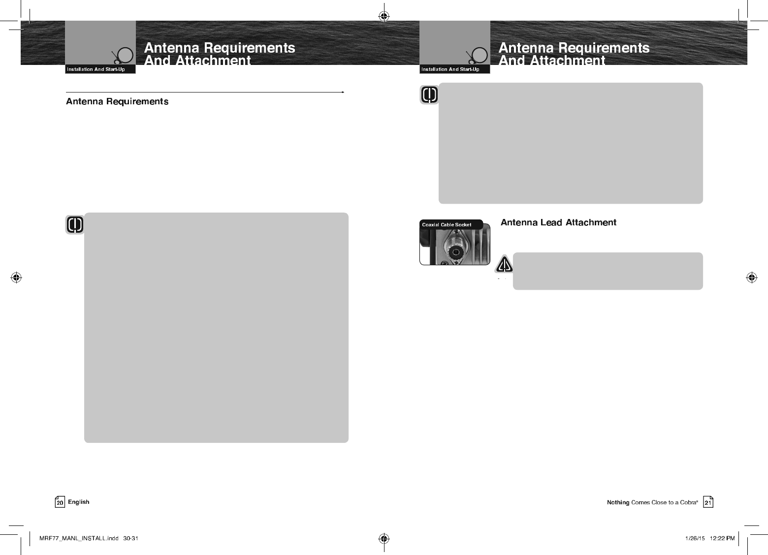
Once the antenna is installed, the Coaxial Cable Lead can
be attached to the socket at the back of the transceiver.
CAUTION
Attempting to transmit without an antenna attached will
damage your CobraMarine VHF radio.
External Devices And Connections
Your CobraMarine VHF radio is set up to connect auxiliary devices for navigation,
convenience, and added versatility. As is the case with the antenna, choosing these
devices is best done with the advice and guidance of a knowledgeable dealer.
Standard connectors are provided on the front and back of the transceiver.
An External Speaker can provide greater volume to hear messages than the speaker
incorporated in the CobraMarine microphone/speaker.
To Install An External Speaker:
1. Connect the wires to the External Speaker as follows:
Orange wire - +Positive connection
Black wire - -Negative connection (Black wire is common shared -Negative for
the External Speaker and PA output)
2. Make sure to solder, crimp, or twist the wires together firmly and use shrink
tubing or electrical tape to waterproof the connection.
At times, it may be handy to hail other boats or give instructions to line handlers
on the dock. Your CobraMarine VHF radio can be switched to operate in the Public
Address mode through an attached PA speaker.
To Install A Public Address Speaker:
1. Connect the wires to the External Speaker as follows:
Red wire - +Positive connection
Black wire - -Negative connection (Black wire is common shared -Negative for the
External Speaker and PA output)
2. Make sure to solder, crimp, or twist the wires together firmly and use shrink
tubing or electrical tape to waterproof the connection.
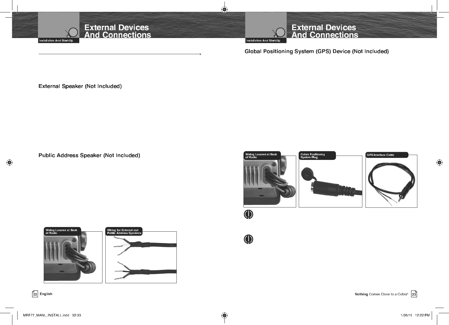
Your Cobra Marine radio does not include a built-in GPS receiver. After connecting an
external GPS receiver, your position will be continuously indicated on the LCD and,
most importantly, it will be included automatically with any DSC Distress message you
may need to send. That will take the “search” out of “search and rescue.
An external GPS input connector has been provided to allow connection to a
back-up GPS receiver.
To Install A GPS Device:
1. Install the GPS device in a convenient location according to its manufacturer’s
directions.
2. Plug-in the optional Cobra C.P.S. (Cobra Positioning System) into the provided
2.5mm jack.
3. Or using the supplied 2-wire adapter wire as follows:
Yellow wire - NMEA 0183 +Data in
Green wire - NMEA 0183 -Data in.
NOTE
Satellite acquisition time is dependent on the antenna mounting location. If the
acquisition takes too long, relocate the radio or use an external GPS receiver.
NOTE
GPS data input is as follows:
• Input voltage (peak to peak): 10V
• Maximum data rate: 4800 baud
• Impedance: 4KΩ
Getting Started
Refer to the foldout on the front cover of this manual to identify the various
controls and indicators on your radio.
Throughout this manual you will be instructed to press or to press and hold
buttons on the transceiver. Press means a momentary press, then release; press and
hold means to hold the button.
When your CobraMarine VHF radio is On, you can expect to hear the following tones
and alarms. The volume of these sounds is controlled by the circuitry in the radio and
is not affected by the volume set with the On-Off Power/Volume knob.
Confirmation Tone
Single high-pitched beep confirms all button presses except the Talk button.
It can be turned On or Off. See set-up routines on page 30.
Error Tone
Three low-pitched beep indicates an invalid button press.
DSC Distress Alarm
High—low—high—low—high. Pause, then repeat. The volume of all alarms will
increase after 10 seconds. Press any button to turn it Off.
NOTE
This alarm sounds only for DSC distress calls on Channel 70.
It does not sound for voice calls on Channel 16 — you still
must listen for those.
Distress Acknowledgement Alarm
High—low—high—low—high. Pause, then repeat. The volume of all alarms will
increase after 10 seconds. Press any button to turn it Off.
DSC Routine Call Alarm
High—pause—high—pause—high. Long pause, then repeat. Press any button to turn
it Off.
DSC Geographical Alarm
Loud, continuous, medium-pitched, high-low tones (warble) — sounds
when a geographical call is received. Press any button to turn it Off.
DSC Position Request Alarm
Medium-loud, continuous, low-pitched series of closely spaced, four (4) beeps [three
(3) short – one (1) long] groups — sounds when a position request call
is received. Press any button to turn it Off.
DSC Individual Alarm
High—pause—high—pause—high. Long pause, then repeat. Press any button to turn
it Off.
Weather Alarm
Medium-loud, continuous, medium-pitched series of one-half (1⁄2) second beeps
spaced one-half (1⁄2) second apart — sounds when weather alert is turned On
and NOAA sends a 1050 Hz weather alert tone on the selected weather channel. Press
any button to turn it Off.
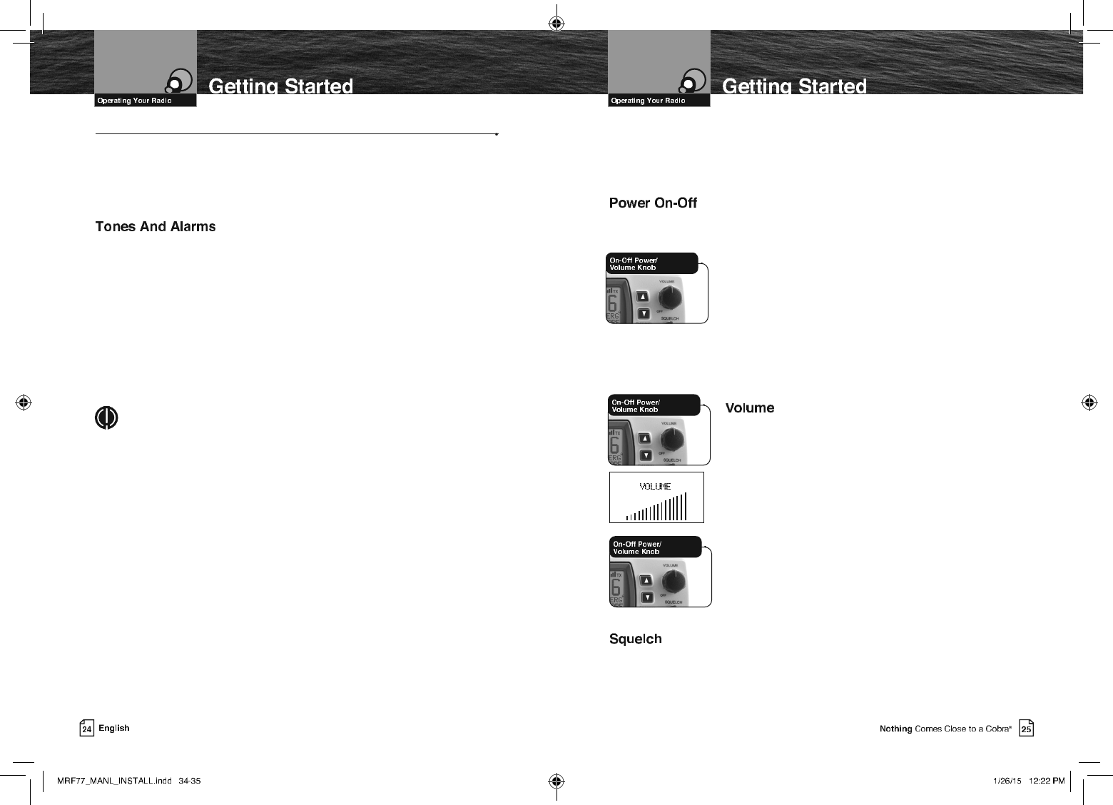
Transceiver power can be turned On or Off by the On-Off Power/Volume
knob on the transceiver.
To Turn Your Radio On Or Off:
1. Rotate the Off Power/Volume knob clockwise to turn on
the transceiver. To turn off the transceiver, rotate the Off
Power/Volume counter clockwise until a “click” is heard.
When the radio is powered On, the confirmation tone
will sound.
The radio will return to the settings in effect when it was
last powered Off, the LCD will show the corresponding
information, and all controls will be operative. The radio
will then be in Standby mode.
The On-Off Power/Volume knob on the transceiver controls the
speaker volume. The volume adjustment applies only to what
you hear from the speaker and does not affect the volume of
your outgoing messages. That is controlled by the circuitry of
your radio. The volume bar graph will be shown to indicate
the volume setting. 2 seconds after finishing the volume
adjustment, the radio will return to the Standby mode.
To Increase The Volume:
• Turn the On-Off Power/Volume knob clockwise.
To Decrease The Volume:
• Turn the On-Off Power/Volume knob counter-clockwise.
Squelch control filters weak signals and radio frequency noise so that you can more
clearly hear the signals you want. You can think of it as a variable barrier that blocks
what you don’t want to hear.
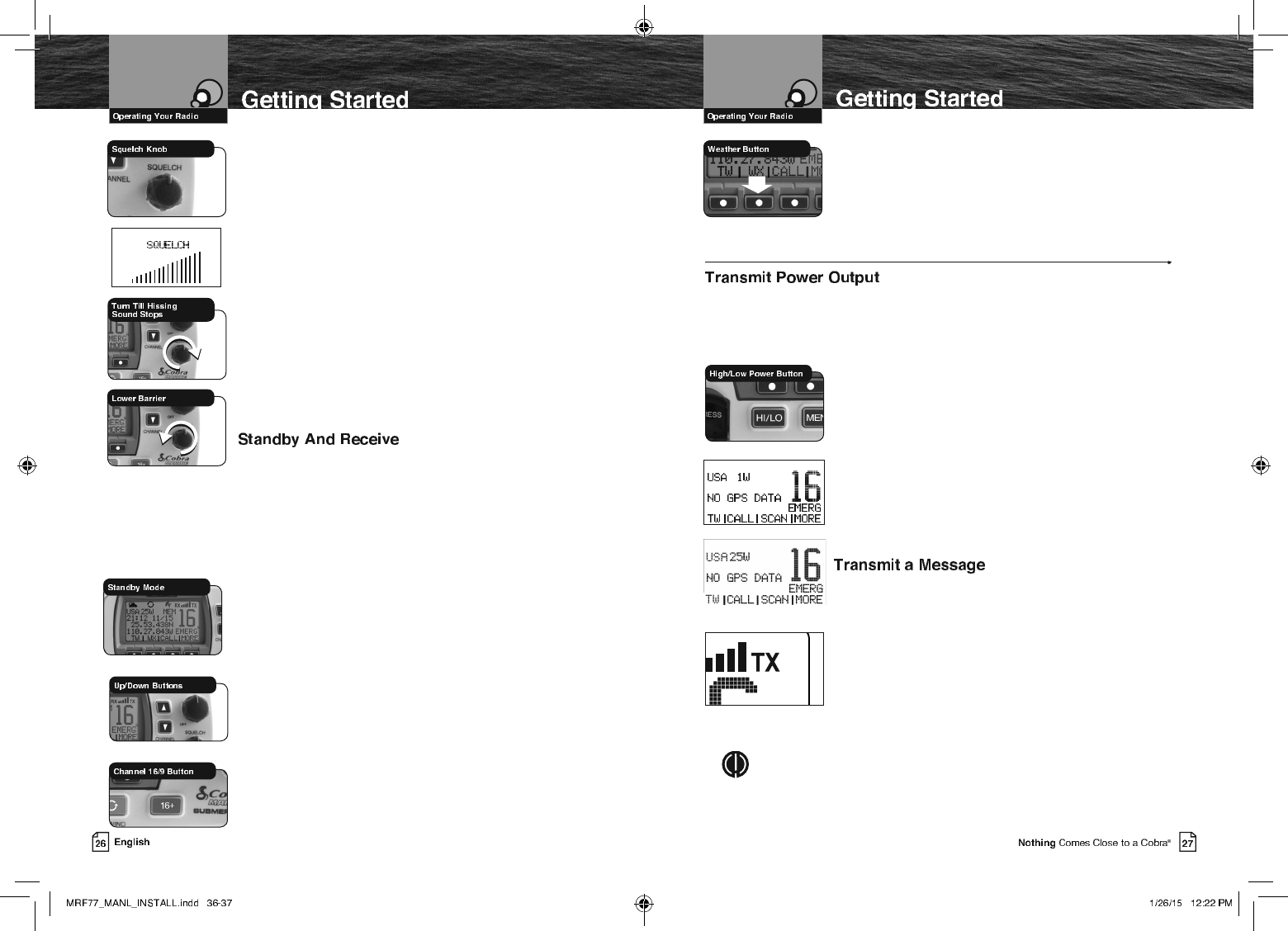
To Squelch Your Radio:
1. With the Squelch knob turned fully counter-clockwise, turn
the On-Off/Volume knob clockwise until you hear
a hissing (noise) sound.
2. Turn the Squelch knob clockwise until the hissing
sound stops.
Turning the Squelch knob further clockwise (higher barrier)
will filter weak and medium strength signals until only the
strongest signal can get through at the highest squelch setting.
The Squelch bar graph will be shown to indicate the Squelch
setting. 2 seconds after finishing the Squelch adjustment, the
radio will return to the Standby mode.
To Receive Weaker Signals:
1. Turn the Squelch knob counterclockwise (lower barrier).
If the squelch is set so that you can hear a continuous hissing
sound, the memory scan and tri-watch functions will be blocked.
Standby mode is the usual mode for the radio whenever it is
turned On.
From Standby Mode, You Can:
Q Change your radio’s settings using set-up routines.
Q Receive messages on the current channel as well
as DSC messages.
Q Listen and Receive NOAA alerts if Weather Alert mode is
turned On.
Q Switch to Transmit mode using the Talk button.
While the radio is in Standby mode, the Receive mode is
entered whenever a strong enough signal to break squelch is
sent to the radio. You will hear the message through whichever
speakers are connected to the radio.
To Change The Channel You Are Listening To,
You Can Choose One Of The Following:
a. Press the Up/Down buttons. This will take you to
the next higher or lower VHF channel. For rapid
advance, press and hold the Up or Down button.
b. Press the Channel 16/9 button. This will take
you to Channel 16 with one (1) press and to Channel 9 with
a second press. Additional presses will toggle between
Channels 16 and 9 and the current user selected channel.
c. To listen to the Weather Radio press the WX (Weather)
soft key. This will activate the weather radio mode. When
in the Weather mode, the Up/Down buttons will change
the weather channel.
d. Press and release the Back softkey to return the radio to
Standby Mode.
HI/LO Transmit Setting
Your radio can Transmit selectively at one (1) or 25 watts of power. Cobra® suggests
you maintain the low power setting for short-range communications and to avoid
overpowering nearby stations with your signal. Use the high power setting for long-range
communications or when you do not receive a response to a signal sent at one (1) watt.
To Toggle Between The High And Low Power Modes:
1. Press the High/Low Power button. The LCD will show which
mode is in effect.
Some channels are restricted to use at a maximum of one
(1) watt. Your radio will automatically set the power to Low
Power mode when you select those channels.
While using the U.S.A. channel map, if, in an emergency,
you need to increase the output power on Channel 13 and
Channel 67 for your signal to be heard, you can override the
Low Power mode by pressing and holding the High/ Low
Power button.
1. Check to see that your unit is set to a proper channel for the
type of message you plan to send.
2. Toggle to the low power setting.
3.
With the microphone about two (2) inches [five (5) cm] from
your mouth, press and hold the Talk button and speak into
the microphone. Transmit will be indicated on the LCD.
4.
Release the Talk button when you are finished speaking. Your
unit can only operate in either the Transmit or the Receive
mode at any given time. You will not hear the response to your
message unless the Talk button is released.
NOTE
If the Talk button is held down for five (5) minutes, the radio will
automatically cease transmitting to prevent unwanted signal generation.
As soon as the Talk button is released, it can be pressed again to
resume transmission.
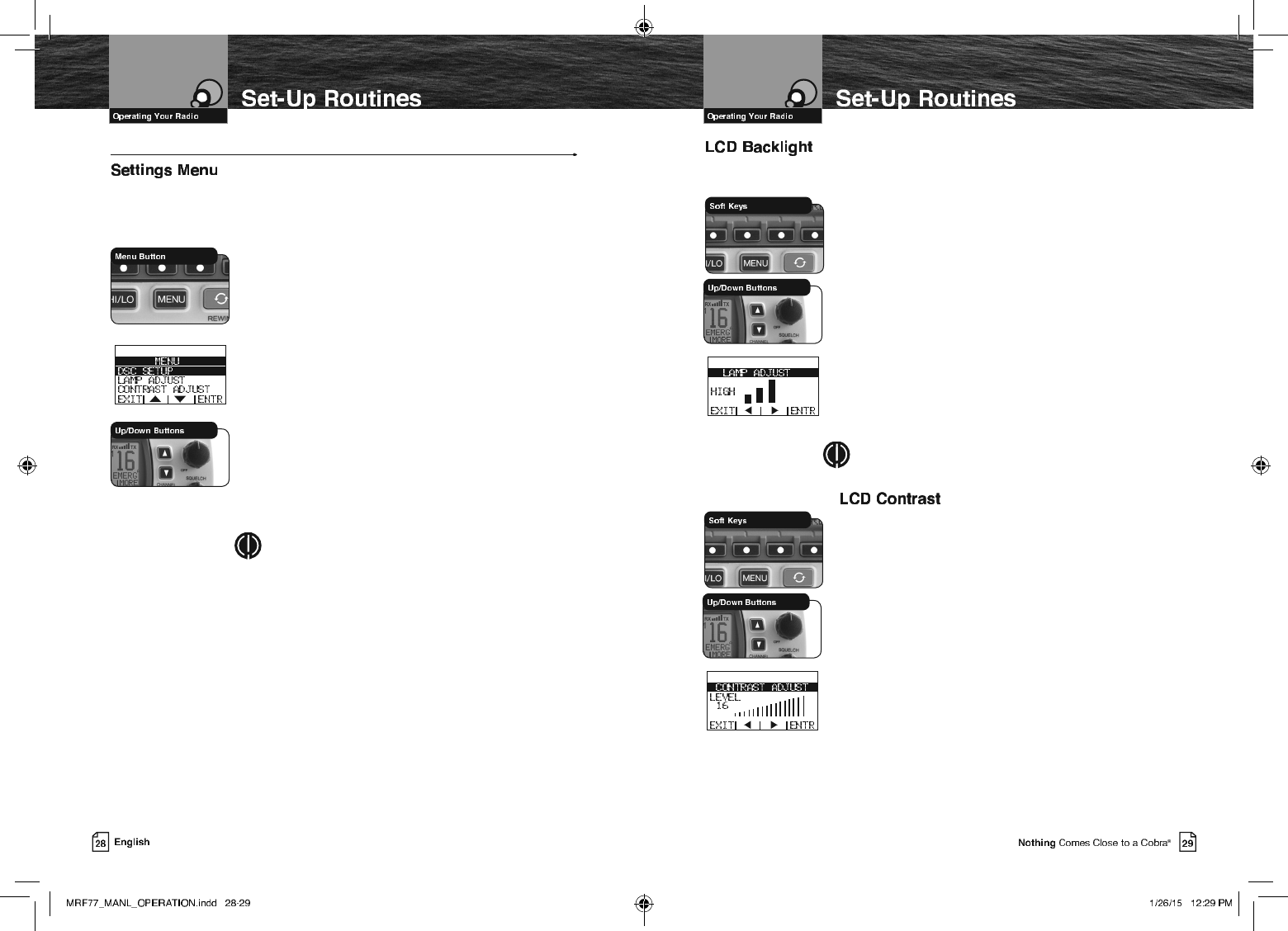
Set-Up Routines
The Settings menu in the CobraMarine VHF radio allows you to turn On and Off many
of its features, to adjust other features to suit your preferences, and to enter your user
MMSI number.
To Enter The Settings Menu:
1. Press the Menu button.
The Settings menu will appear on the LCD.
After entering the Settings menu, you can scroll
through it to make as many entries as you like.
Whenever the setting selection highlight appears in a feature
portion of the menu, it will highlight the setting that was in
effect when you entered the menu.
When you are nished with changes, you can exit the
Settings menu by pressing the Exit soft key and return to
Standby mode.
To Exit The Settings Menu:
1. Use the Up/Down buttons to scroll down to
EXIT at the bottom of the menu, or press the Exit soft key
to move up through the menu until the radio returns to the
Standby mode.
NOTE
Basic set-up routines are described here. For set-up
routines that apply specically to a particular function,
they are included in the section for that function.
The LCD has a Backlight lamp to make it visible in the dark.
This lamp can be adjusted for brightness or turned Off.
To Adjust The Backlight Level:
1. Enter the Settings menu and scroll to LAMP ADJ with the
Up/Down soft keys or using the Up/Down channel buttons.
2. Press the ENTR soft key and observe the current backlight
setting — HIGH, MEDIUM, LOW or OFF.
3. Use the Up/Down buttons or Right/Left soft keys to switch to
the setting you want.
4. Press the ENTR soft key to select the backlight setting. Or
press the EXIT soft key to EXIT without making changes
to the backlight setting.
5. The radio will return to the Settings menu. The radio will
remember the saved backlight setting, when powering off
the radio, or disconnecting power to the radio.
NOTE
If the backlight is set to off, ANY key press will activate the
backlight at the lowest setting.
The LCD backlight will not be visible in daylight, but the LCD
Contrast can be adjusted to make it easier to read in
different light conditions.
To Change The Contrast:
1. Enter the Settings menu and scroll to CONTRAST
ADJUST Up/Down soft keys or the UP/Down channel
buttons.
2. Press the ENTR soft key and observe the current contrast
setting — a number between one 0 and 16.
3. Use the Up/Down buttons or the Right/Left soft keys to
change the number up or down
4. Press the ENTR soft key to select a contrast level. Or press
the EXIT soft key to EXIT without making changes to the
Contrast setting.
5. The radio will return to the settings menu. The radio will
remember the saved contrast level, when powering off the
radio, or disconnecting power to the radio.
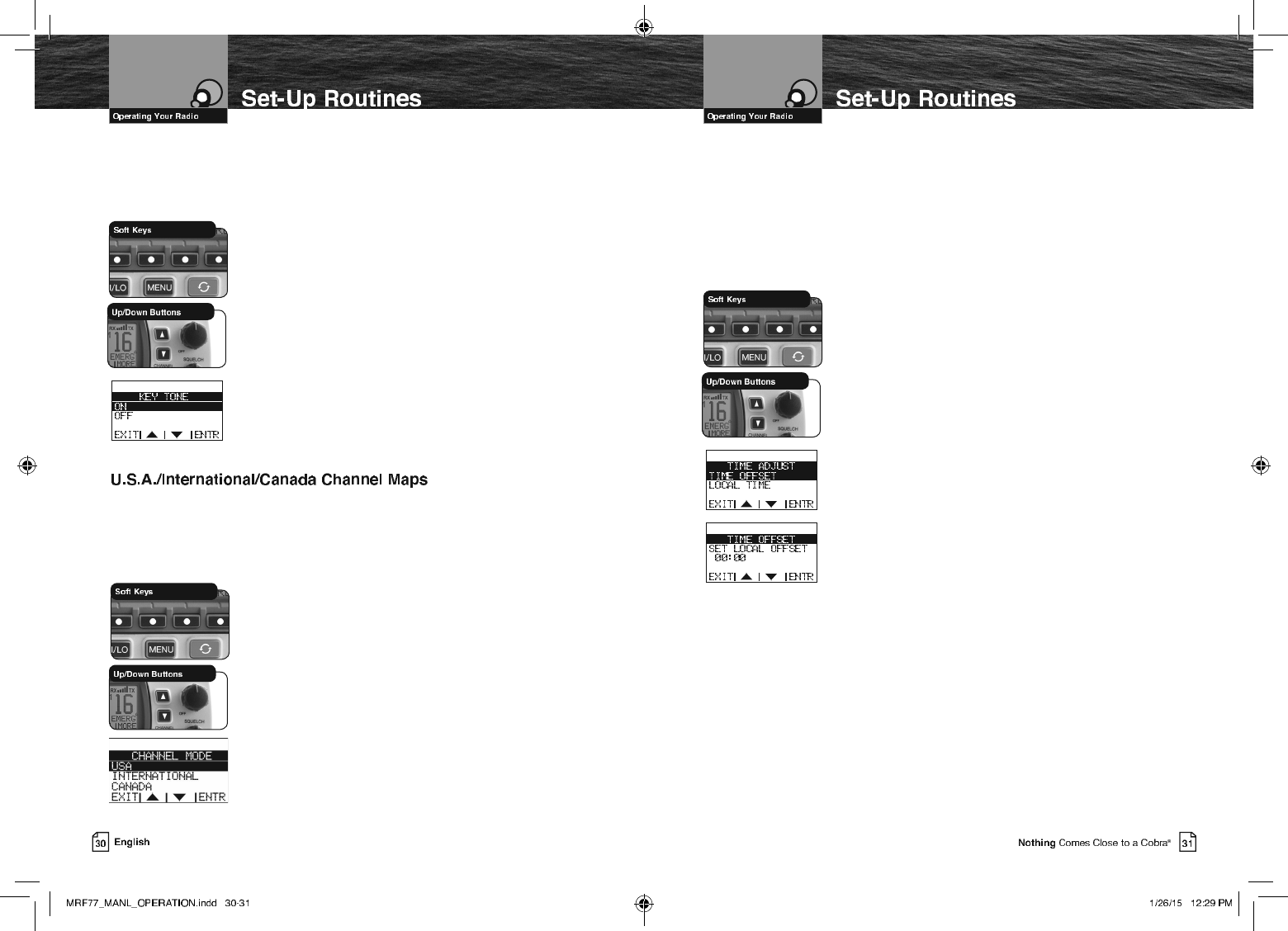
&RQÀUPDWLRQ7RQH
The Conrmation Tone sounds when your CobraMarine VHF radio is turned On
and to conrm all button presses except for the Talk button. If you would prefer
not to hear the Conrmation Tone, you can turn it Off and On as you choose.
To Turn The Conrmation Tone On Or Off:
1. Enter the Settings menu and scroll to KEY TONE
with the Up/Down soft keys or the Up/Down channel
buttons.
2. 2. Press the ENTR soft key and observe the current
conrmation tone setting — ON or OFF.
3. Use the Up/Down soft keys or the Up/Down channel
buttons to switch to the setting you want.
4. 4. Press the ENTR soft key to select the setting. Or press
the EXIT soft key to EXIT without making changes to the
Key Tone setting.
5. The radio will return to the settings menu. The radio will
remember the saved Key Tone setting, when powering off
the radio, or disconnecting power to the radio.
Three (3) sets of VHF Channel Maps have been established for marine use in the
U.S.A., Canada, and the rest of the world (International). Most of the channels are the
same for all three (3) maps, but there are denite differences (see table on pages 66
through 78). Your radio has all three (3) maps built into it and will operate correctly in
whichever area you choose.
To Set Your Radio For The Area In Which You Will Be Using
It:
1.
Enter the Settings menu and scroll to CHANNEL
MODE with
the Up/Down soft keys or the Up/Down channel buttons.
2. Press the ENTR soft key and observe the current channel
mode setting — USA,INTERNATIONAL, or CANADA.
3. Use the Up/Down soft keys or the Up/Down channel buttons
to switch to the setting you want.
4. Press the ENTR soft key to select the setting. Or press the
EXIT soft key to EXIT without making changes to the
Channel Mode setting
5. The radio will return to the settings menu. The radio will
remember the saved Key Tone setting, when powering off
the radio, or disconnecting power to the radio
7LPH$GMXVW
All VHF, DSC, and GPS activities use a 24-hour clock and Universal Coordinated Time
(UTC) which was formerly known as Greenwich Mean Time (GMT). Time Adjust uses
your built-in GPS to gather time input. Time Adjust will allow the radio to display the
time as Local time or UTC time. For time input to be converted to local time, you need
to enter the hour offset of your local time zone from Greenwich. (See world city time
zone chart on page 80). You can also choose to have the time displayed in a 12 or 24
hour format
To Change The Time Offset:
1. Enter the Settings menu and scroll to TIME ADJUST
with the Up/Down soft keys or the Up/Down channel
buttons.
2. Highlight the TIME OFFSET option in the menu.
3. Press the ENTR key and observe the current setting.
4. Use the Up/Down soft keys or the UP/Down channel
buttons to change the setting for your local time zone.
5. Press the ENTR soft key to select the setting. Or press the
EXIT soft key to EXIT without making changes to the
Local Time Zone setting.
6.
The radio will return to the Time Adjust menu. The radio
will remember the saved Local Time Zone setting, when
powering off the radio, or disconnecting power to the radio.
To Select UTC or Local Time Display:
1. Enter the Settings menu and scroll to TIME ADJUST
with the Up/Down soft keys or the Up/Down channel
buttons.
2. Highlight the LOCAL TIME option in the menu.
3. Press the ENTR key and observe the current setting.
4. Use the Up/Down soft keys or the UP/Down channel
buttons to change the setting for how the radio will display
the time (UTC or Local).
5. Press the ENTR soft key to select the setting. Or press the
EXIT soft key to EXIT without making changes to the
Local Time setting.
6.
The radio will return to the Time Adjust menu. The radio
will remember the saved Local Time Zone setting, when
powering off the radio, or disconnecting power to the radio.
To Select 12 or 24 Hour Format Time Display:
1. Enter the Settings menu and scroll to TIME ADJUST
with the Up/Down soft keys or the Up/Down channel buttons.
2. Highlight the 12H/24H TIME DISP option in the menu.
3. Press the ENTR key and observe the current setting.
4. Use the Up/Down soft keys or the UP/Down channel
buttons to change the setting for how the radio will
display the time (12 Hour or 24 Hour format).
5. Press the ENTR soft key to select the setting. Or press the
EXIT soft key to EXIT without making changes to the
time format display setting.
6. The radio will return to the Time Adjust menu. The radio
will remember the saved 12 or 24 hour radio display
setting, when powering off the radio, or disconnecting
power to the radio.
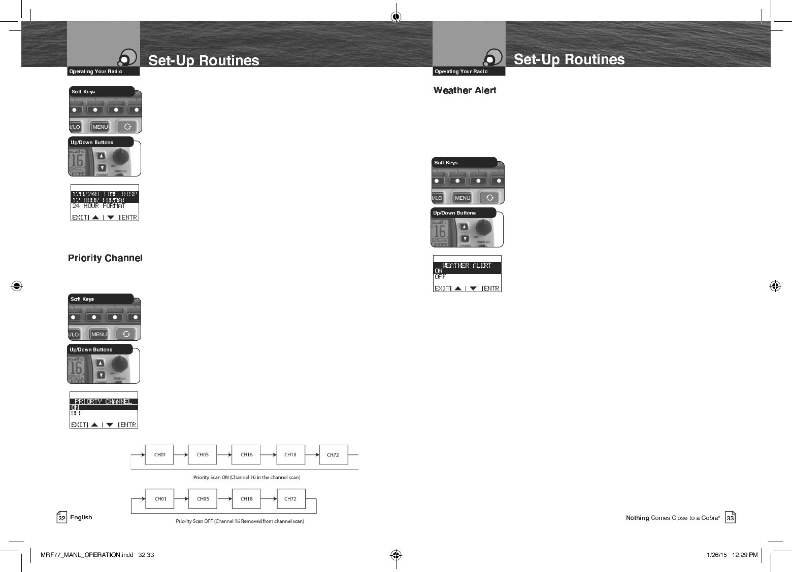
This setting will allow you to choose whether channel 16 is or is not included when
channel scanning.
To Turn The Priority Channel On Or Off:
1. Enter the Settings menu and scroll to PRIORITY
CHANNEL with the Up/Down soft keys or the Up/Down
channel buttons.
2. Press the ENTR soft key and observe the current priority
channel setting — ON or OFF.
3. Use the Up/Down soft keys or the Up/Down channel
buttons to switch to the setting you want.
4. Press the ENTR soft key to select the setting. Or press the
EXIT soft key to EXIT without making changes to the
priority channel setting.
5.
The radio will return to the settings menu. The radio
will remember the saved priority channel setting, when
powering off the radio, or disconnecting power to the radio.
To Select 12 or 24 Hour Format Time Display:
1. Enter the Settings menu and scroll to TIME ADJUST
with the Up/Down soft keys or the Up/Down channel buttons.
2. Highlight the 12H/24H TIME DISP option in the menu.
3. Press the ENTR key and observe the current setting.
4. Use the Up/Down soft keys or the UP/Down channel
buttons to change the setting for how the radio will
display the time (12 Hour or 24 Hour format).
5. Press the ENTR soft key to select the setting. Or press the
EXIT soft key to EXIT without making changes to the
time format display setting.
6. The radio will return to the Time Adjust menu. The radio
will remember the saved 12 or 24 hour radio display
setting, when powering off the radio, or disconnecting
power to the radio.
This setting will allow you to choose whether channel 16 is or is not included when
channel scanning.
To Turn The Priority Channel On Or Off:
1. Enter the Settings menu and scroll to PRIORITY
CHANNEL with the Up/Down soft keys or the Up/Down
channel buttons.
2. Press the ENTR soft key and observe the current priority
channel setting — ON or OFF.
3. Use the Up/Down soft keys or the Up/Down channel
buttons to switch to the setting you want.
4. Press the ENTR soft key to select the setting. Or press the
EXIT soft key to EXIT without making changes to the
priority channel setting.
5.
The radio will return to the settings menu. The radio
will remember the saved priority channel setting, when
powering off the radio, or disconnecting power to the radio.
This setting will allow you to choose whether activate the Weather Alert feature.
When NOAA broadcasts a Weather Alert Signal and your radio is in the Weather Alert
mode, you will hear a continuous audible tone and the radio will automatically switch
to Weather Radio mode. The alert indicators will sound regardless of what channel
you are operating on as soon as a NOAA alert signal is received
To Turn Weather Alert On Or Off:
1. Enter the Settings menu and scroll to WEATHER ALERT
with the Up/Down soft keys or the Up/Down channel buttons.
2. Press the ENTR soft key and observe the current Weather
Alert setting — ON or OFF.
3. Use the Up/Down soft keys or the Up/Down channel
buttons to switch to the setting you want.
4. Press the ENTR soft key to select the setting. Or press the
EXIT soft key to EXIT without making changes to the
Weather Alert setting. The radio will turn on the Weather
Icon and Weather Alert Icon to indicate that the Weather
Alert is active.
5.
The radio will return to the settings menu. The radio will
remember the saved Weather Alert setting, when powering
off the radio, or disconnecting power to the radio.
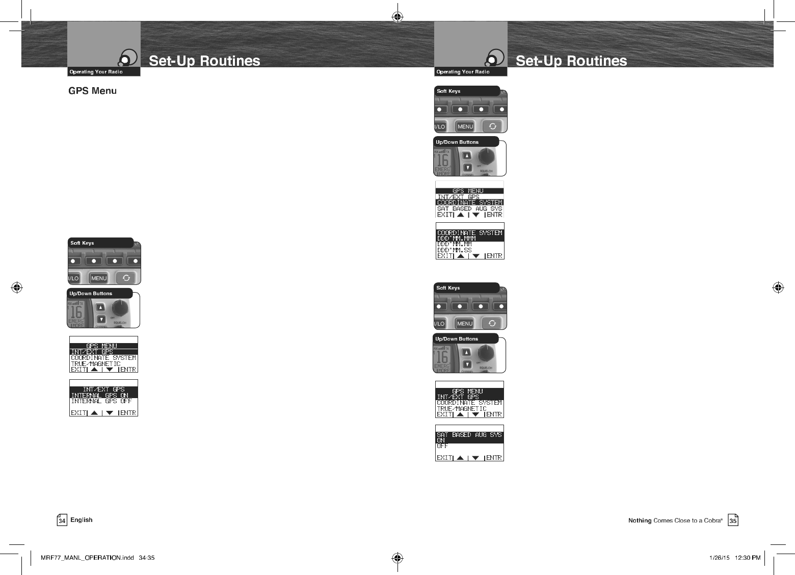
To Select the Coordinate System:
1. Enter the Settings menu and scroll to GPS MENU
with the Up/Down soft keys or the Up/Down channel
buttons.
2. Highlight the COORDINATE
SYSTEM
option in the menu.
3. Press the ENTR key and observe the current setting.
4. Use the Up/Down soft keys or the UP/Down channel
buttons to change the setting to use the desired
coordinate system.
5. Press the ENTR soft key to select the setting. Or press the
EXIT soft key to EXIT without making changes to the
Coordinate System setting.
6.
The radio will return to the GPS menu. The radio will
remember the saved Coordinate System setting, when
powering off the radio, or disconnecting power to the radio.
To Select the Satellite Based Augmentation System:
1. Enter the Settings menu and scroll to GPS MENU
with the Up/Down soft keys or the Up/Down channel
buttons.
2. Highlight the SAT BASED AUG SYS option in the menu.
3. Press the ENTR key and observe the current setting.
4. Use the Up/Down soft keys or the Up/Down buttons to
select the desired setting.
5. Press the ENTR soft key to select the setting. Or press the
EXIT soft key to EXIT without making changes to the Sat
Based Aug Sys setting.
6. The radio will return to the GPS menu. The radio will
remember the saved Sat Based Aug Sys setting, when
powering off the radio, or disconnecting power to the
radio.
All VHF Marine radios SHOULD / NEED to have a GPS receiver connected and operating
to effectively use the DSC (Digital Selective Calling) features built-in to the radios.
In an Emergency you want the rescue authorities and surrounding vessels to know
where you are and to be able to quickly assist you in your time of need. Your MR F77
radio has a GPS receiver built right in!
This menu allows you to select the internal GPS receiver (already selected by default),
select and external GPS receiver, select the coordinate system which is basically the
accuracy (the most accurate setting is already selected by default), Select the Satellite
Based Augmentation System to be enabled or turned off (some areas on Earth need
this turned off for greater accuracy)(defaulted On), and allows you to test the GPS
receiver (will test either the internal or an external GPS receiver) to be sure that you
are receiving good satellite information and check the GPS signal strength.
To Select the Internal or an External GPS Receiver:
1. Enter the Settings menu and scroll to GPS MENU
with the Up/Down soft keys or the Up/Down channel
buttons.
2. Highlight the INT/EXT GPS option in the menu.
3. Press the ENTR key and observe the current setting.
4. Use the Up/Down soft keys or the UP/Down channel
buttons to change the setting to use the internal GPS or
turn off the internal GPS to use and external GPS.
5. Press the ENTR soft key to select the setting. Or press the
EXIT soft key to EXIT without making changes to the
GPS setting.
6. The radio will return to the GPS menu. The radio will
remember the saved GPS setting, when powering off the
radio, or disconnecting power to the radio.
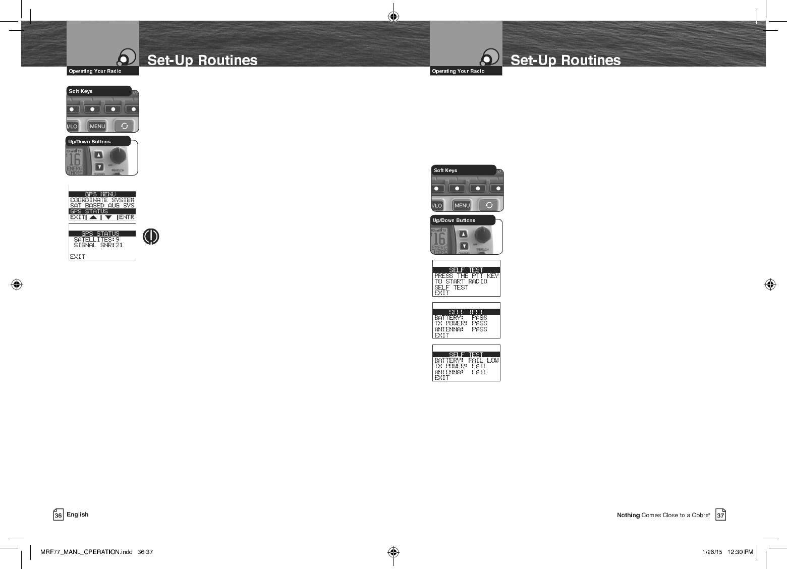
5DGLR6HOI7HVW
Your CobraMarine radio includes a Self Test feature to allow you to test the input
battery voltage, the output transmit power, and the Antenna! This is the perfect test
before you head out from the dock to insure your radio is fully operational and is
ready, willing, and able to assist you for your communications needs and in case of
emergency.
To Select the Radio Self Test Screen:
1. Enter the Settings menu and scroll to SELF TEST
with the Up/Down soft keys or the Up/Down channel
buttons.
2. Press the ENTR soft key and observe the current setting.
3. Press and release the Transmit button on the Microphone
to start the test.
4. The Self Test screen reports the following information:
a. Battery input voltage. Shown as a PASS or FAIL. If a
FAIL is reported, then this will show either HIGH
(battery voltage is too high) or LOW (battery voltage is
too low).
b. Radio Transmitter Power. Shown as a PASS or FAIL.
If a FAIL is reported, the RF output power is incorrect.
Check the installation of the radio to ensure proper
solid connections to power and the antenna.
c. Antenna status. Shown as a PASS or FAIL. If a FAIL is
reported, the antenna impedance is incorrect, open or
shorted.
5. Press the EXIT soft key to EXIT the Self Test screen.
The radio will return to the menu.
To Select the GPS Status Screen:
1. Enter the Settings menu and scroll to GPS MENU
with the Up/Down soft keys or the Up/Down channel
buttons.
2. Highlight the GPS STATUS option in the menu.
3. Press the ENTR key and observe the current setting.
4. The GPS Status screen reports the following information:
a. How many satellites are currently being tracked.
b. The overall health of the GPS satellite signals being
received.
5. Press the EXIT soft key to EXIT the GPS Status screen.
6. The radio will return to the GPS menu.
NOTE
The larger the signal SNR number the better the GPS
signal strength.
DSC Set-Up
Digital selective calling — DSC — employs digital RF signals which tend to carry
further and be less susceptible to distortion from noise and atmospheric conditions
than analog ones. The result is greater range and more reliable message delivery
per watt of output power.
But, that is not the only advantage of DSC equipped radios. Those radios are set up to
interface with GPS and to automate many of the operations involved in sending and
receiving messages. That results in more compact and accurate messages and less
congestion of the airwaves.
The price of these benets to the user is the time it takes to do the required set-up
to make the DSC features work. A little time spent when your radio is new will pay
dividends over its life.
These procedures use the Settings menu. Refer to page 28 for information on entering
and exiting the Settings menu.
8VHU006,1XPEHU
The nine (9) digit MMSI number, similar to a telephone number, is a unique identier
for a vessel. DSC incorporates this number into every message that is Sent (Tx) or
Received (Rx). Enter the MMSI number as soon as you receive your MMSI number
from the issuing agency listed on page 9.
NOTE
The radio does not operate in the DSC mode until an ofcial MMSI number is
entered. An error tone will sound when attempting to operate in the DSC mode
without an MMSI number.
NOTE
An MMSI number can only be entered one time. To enter a new MMSI number,
please contact Cobra customer service.
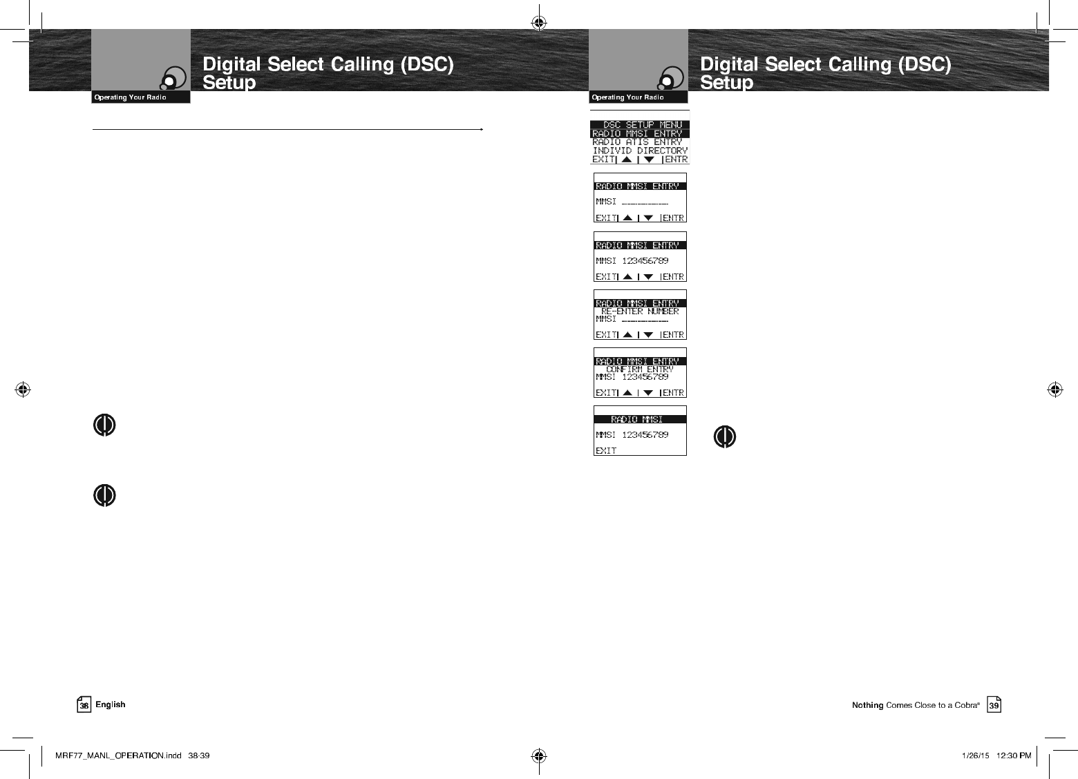
To Enter Your MMSI Number:
1. Enter the Settings menu and scroll to DSC SETUP
with the Up/Down soft keys or the channel Up/Down
buttons.
2. Press the ENTR soft key and scroll to RADIO MMSI
ENTRY with the Up/Down soft keys or the channel Up/
Down buttons.
3. Press the ENTR soft key . The blinking cursor will appear
at the rst digit under RADIO MMSI ENTRY.
4. Use the Up/Down soft keys or the channel Up/Down
buttons to scroll through the number list to the rst digit
of your number.
5. Press the ENTR soft key to select the digit and the
blinking cursor will move to the next digit of the number.
6. Repeat steps 3 and 4 until all nine (9) digits of your
MMSI number are entered.
7. Check that you have entered the number correctly. The
radio will ask you to re-enter your number to conrm.
8. Press ENTR soft key to save the MMSI number and the
radio will return to the DSC SETUP MENU.
NOTE
After the MMSI number has been entered, the RADIO
MMSI ENTRY menu option will move to the bottom
of the DSC SETUP MENU. This is done because the
MMSI entry is entered only once.
,I<RX,QFRUUHFWO\(QWHU<RXU006,1XPEHU
YOU CAN DO THIS ONLY ONCE! An attempt to enter an MMSI number again will result
in an error message as shown.
Pressing the EXIT soft key from the error message will return the radio to the DSC
SETUP MENU.
Once the error message appears, the radio will still operate in all non-DSC modes.
But you will have to contact Cobra® Electronics (see product service on page 84 for
details) for reset before you can enter a new MMSI number into the radio.
Because the MMSI number is so important to DSC operation, this limitation is imposed
on all DSC capable radios to prevent constant changes and the potential introduction
of errors in the process.
,I<RX7UDQVIHU<RXU5DGLR7R$'LIIHUHQW9HVVHO
Contact the MMSI issuing agency from which you obtained your number and change the
information associated with your number to correspond to vessel in which it will be mounted.
To View Your MMSI Number At Any Time:
1. Enter the DSC SETUP MENU menu and scroll to
RADIO MMSI ENTRY with the Up/Down soft keys or
the Up/Down channel buttons.
2. Press the ENTR button and the already entered number
will be displayed.
3.
Press the EXIT soft key to return to the DSC SETUP MENU.
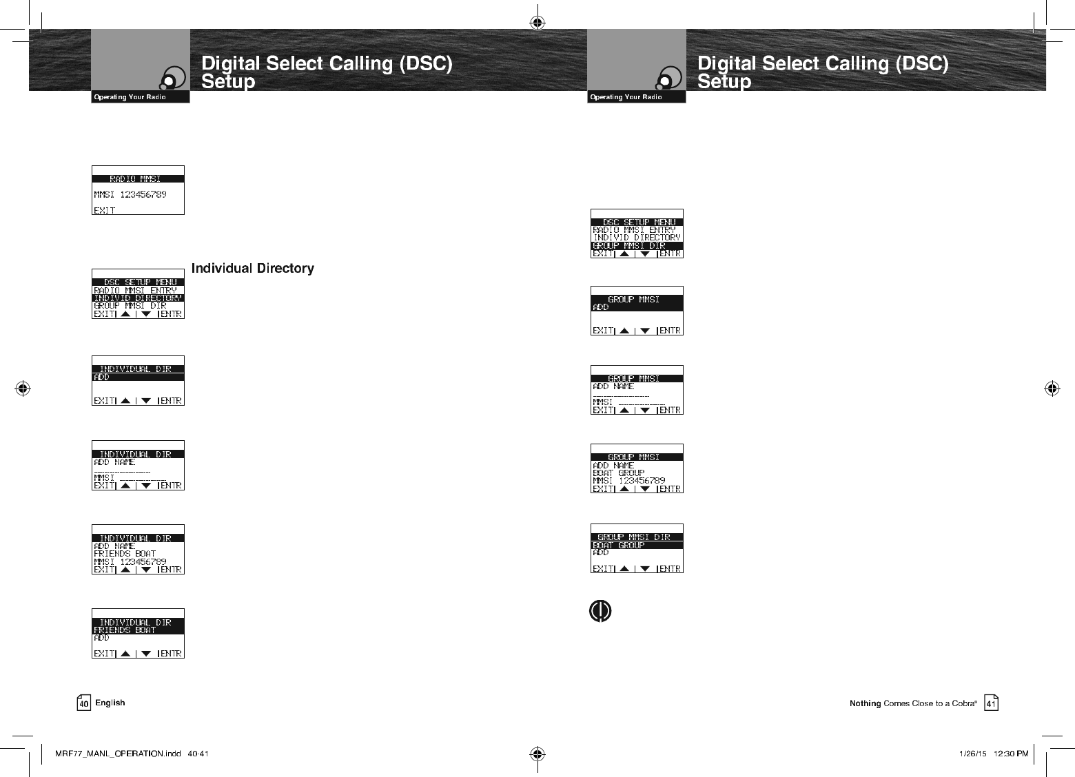
DSC calling allows you to call another vessel or station directly if
you know its MMSI number. Your CobraMarine VHF radio allows
you to store up to twenty (20) names and their associated MMSI
numbers for quick access.
To Enter Or Edit Names And MMSI Numbers In The Directory:
1. Enter the DSC SETUP MENU and scroll to INDIVID
DIRECTORY (individual directory) with the Up/Down soft
keys or the Up/Down channel buttons.
2. The ADD option in the menu will be highlighted the rst
time this menu is entered. Press the ENTR soft key to
ADD a new Name and MMSI number.
3. The cursor will begin to blink at the rst character under
ADD NAME.
4. Use the Up/Down soft keys or the Up/Down channel
buttons to scroll through the character list.
5. Press the ENTR soft key to select a character. This will
also move the blinking cursor to the next character under
ADD NAME.
6. Repeat steps 5 and 6 to enter additional characters — up
to a maximum of eleven (11) — for the name.
7. After entering the name, press the ENTR soft key to move
the blinking cursor to the rst character under MMSI.
8. Use the Up/Down soft keys or the Up/Down channel buttons
to scroll through the number list.
9. Press the ENTR soft key to select the number and move the
cursor to the next character under MMSI.
10. Repeat steps 9 and 10 until the ninth (9) digit MMSI is entered.
11. Press the ENTR button to save the entry.
12. Highlight ADD to enter the next new name/MMSI number
entry, or highlight the entry just entered and press the ENTR
soft key to edit or delete the current entry, or press the EXIT
soft key to return to the DSC SETUP MENU.
*URXS006,1XPEHU
Nautical organizations such as yacht clubs and the organizers of events such as regattas can
establish Group MMSIs. These allow a message to be sent automatically to all members of
the group without having to call each one individually.
Each member of the group must enter the group MMSI number in his radio in order to
receive group messages.
To Enter A Group MMSI Number:
1. Enter the DSC SETUP MENU and scroll to GROUP MMSI
DIR (group MMSI) with the Up/Down soft keys or the
Up/Down channel buttons.
2. The ADD option in the menu will be highlighted the rst
time this menu is entered. Press the ENTR soft key to
ADD a new Name and MMSI number.
3. The cursor will begin to blink at the rst character under
ADD NAME.
4. Use the Up/Down soft keys or the Up/Down channel
buttons to scroll through the character list.
5. Press the ENTR soft key to select a character. This will
also move the blinking cursor to the next character under
ADD NAME.
6. Repeat steps 5 and 6 to enter additional characters — up
to a maximum of eleven (11) — for the name.
7.
After entering the name, press the ENTR soft key to move
the blinking cursor to the second character under MMSI
(the rst digit of a Group MMSI number always starts with a 0).
8. Use the Up/Down soft keys or the Up/Down channel
buttons to scroll through the number list.
9. Press the ENTR soft key to select the number and move
the cursor to the next character under MMSI.
10. Repeat steps 9 and 10 until the ninth (9) digit MMSI is entered.
11. Press the ENTR button to save the entry.
12. Highlight ADD to enter the next new name/MMSI number
entry, or highlight the entry just entered and press the ENTR
soft key to edit or delete the current entry, or press the EXIT
soft key to return to the DSC SETUP MENU.
NOTE
The group MMSI is established by modifying the MMSI assigned to one (1) of the
group members. The last digit of that member’s MMSI number is dropped and a zero
(0) is inserted at the beginning. For example, member MMSI number 366123456
becomes group MMSI number 036612345.
Group MMSIs can be entered and changed any number of times
without encountering the need to have your radio reset