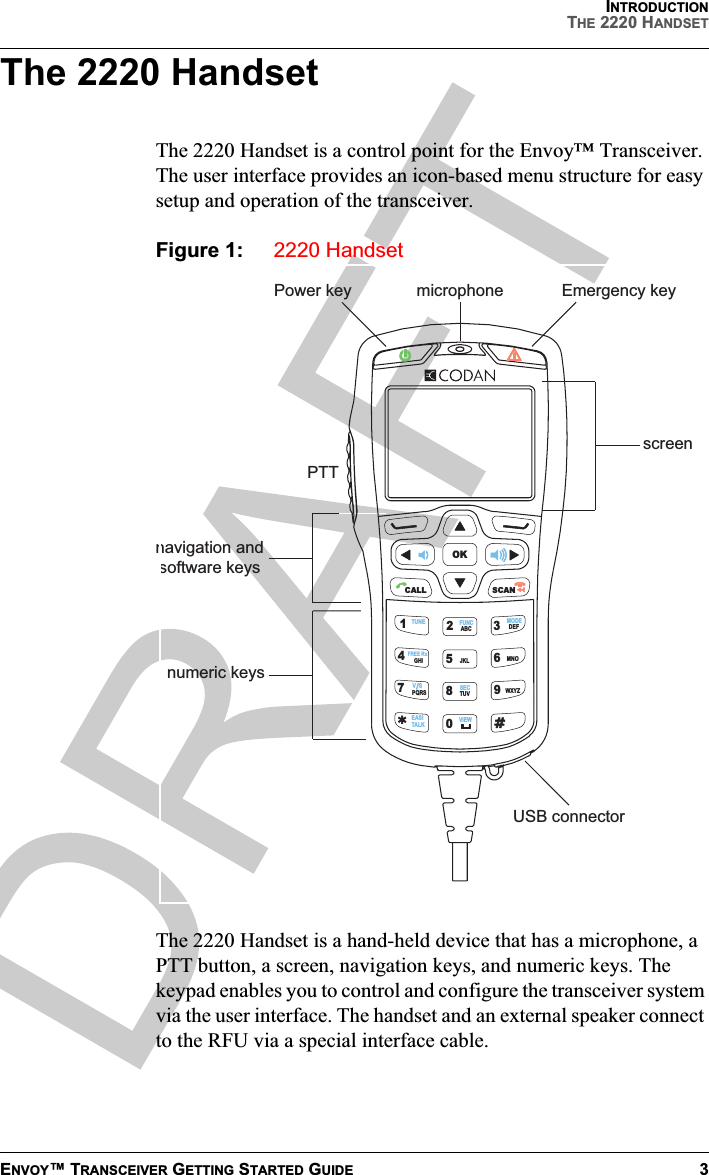
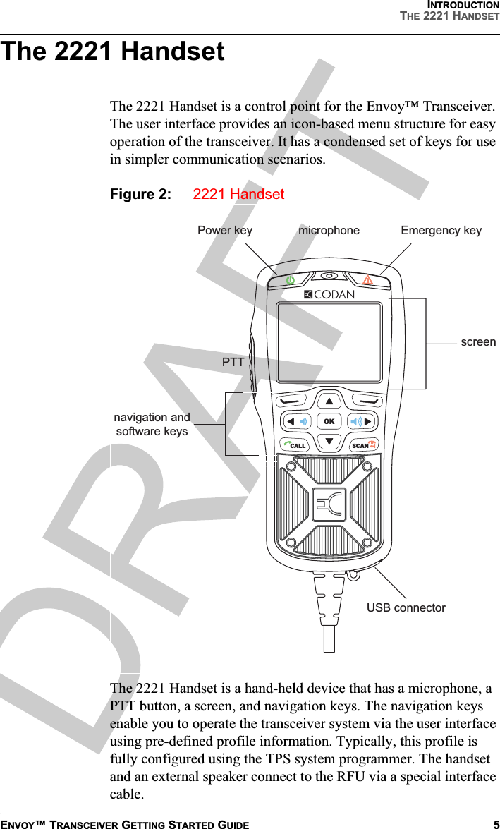
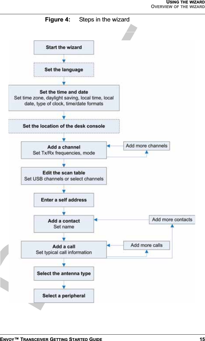
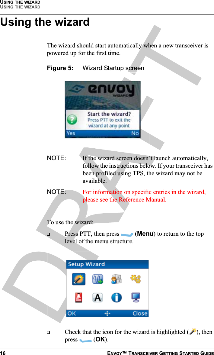
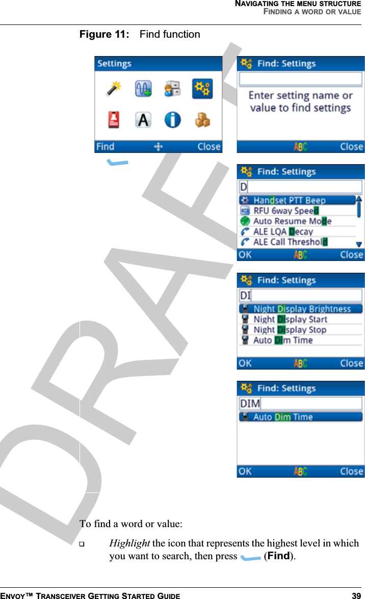
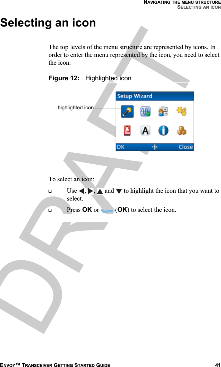
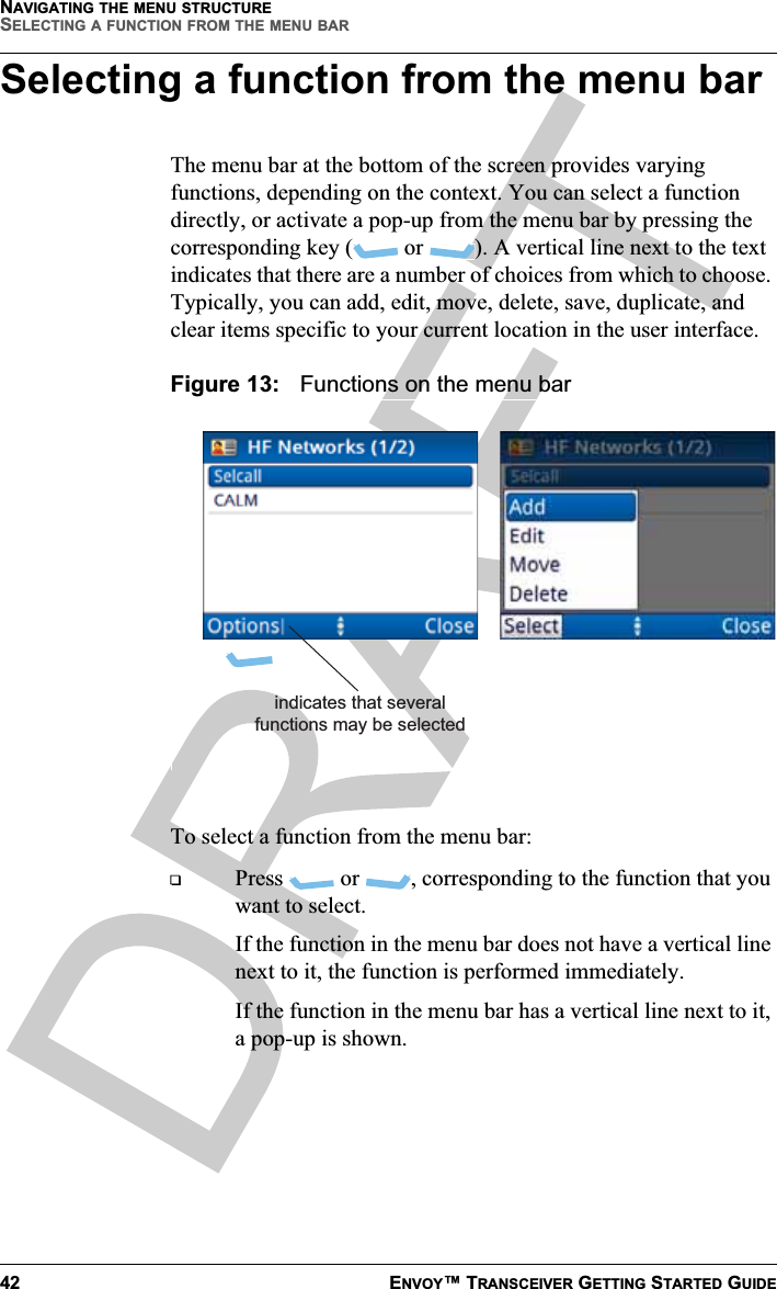
Codan 2210 2210 HF Radio System User Manual

Codan Limited 2210 HF Radio System

User Manual

RADIO COMMUNICATIONSGetting Started GuideEnvoy™ Transceiver
No part of this manual may be reproduced, transcribed, translated into any language or transmitted in any form whatsoever without the prior written consent of Codan Limited.© Copyright 2012–2013 Codan Limited.Codan part number 15-04177-EN Issue 3, June 2013.CODAN™, Envoy™, Easitalk™, and CALM™ are trademarks of Codan Limited. Other brand, product, and company names mentioned in this document are trademarks or registered trademarks of their respective holders.The English version takes precedence over any translated versions.
TABLE OF CONTENTSENVOY™ TRANSCEIVER GETTING STARTED GUIDE iTable of contentsSection 1 IntroductionOverview of this guide   .  .  .  .  .  .  .  .  .  .  .  .  .  .  .  .  .  .  .  .   1The 2220 Handset    .  .  .  .  .  .  .  .  .  .  .  .  .  .  .  .  .  .  .  .  .  .   3The 2221 Handset    .  .  .  .  .  .  .  .  .  .  .  .  .  .  .  .  .  .  .  .  .  .   5The 2230 Desk Console    .  .  .  .  .  .  .  .  .  .  .  .  .  .  .  .  .  .  .   7Keypad   .  .  .  .  .  .  .  .  .  .  .  .  .  .  .  .  .  .  .  .  .  .  .  .  .  .  .  .   8Accessing the CD .  .  .  .  .  .  .  .  .  .  .  .  .  .  .  .  .  .  .  .  .  .  . 11Standards and icons .  .  .  .  .  .  .  .  .  .  .  .  .  .  .  .  .  .  .  .  .  . 12Section 2 Using the wizardOverview of the wizard .  .  .  .  .  .  .  .  .  .  .  .  .  .  .  .  .  .  .  . 14Using the wizard   .  .  .  .  .  .  .  .  .  .  .  .  .  .  .  .  .  .  .  .  .  .  . 16Selecting a language    .  .  .  .  .  .  .  .  .  .  .  .  .  .  .  .  .  .  . 17Setting the time and date   .  .  .  .  .  .  .  .  .  .  .  .  .  .  .  .  . 17Setting the location of the desk console    .  .  .  .  .  .  .  .  . 18Adding a channel  .  .  .  .  .  .  .  .  .  .  .  .  .  .  .  .  .  .  .  .  . 19Entering a self address   .  .  .  .  .  .  .  .  .  .  .  .  .  .  .  .  .  . 21Adding a contact   .  .  .  .  .  .  .  .  .  .  .  .  .  .  .  .  .  .  .  .  . 22Selecting an antenna    .  .  .  .  .  .  .  .  .  .  .  .  .  .  .  .  .  .  . 29Selecting a peripheral device  .  .  .  .  .  .  .  .  .  .  .  .  .  .  . 30Section 3 Navigating the menu structureThe basic menu structure  .  .  .  .  .  .  .  .  .  .  .  .  .  .  .  .  .  .  . 32Navigating the menu structure   .  .  .  .  .  .  .  .  .  .  .  .  .  .  .  . 34Overview of basic and advanced views    .  .  .  .  .  .  .  .  .  .  . 36Basic view    .  .  .  .  .  .  .  .  .  .  .  .  .  .  .  .  .  .  .  .  .  .  .  . 36
TABLE OF CONTENTSii ENVOY™ TRANSCEIVER GETTING STARTED GUIDEAdvanced view     .  .  .  .  .  .  .  .  .  .  .  .  .  .  .  .  .  .  .  .  . 36Switching between basic and advanced views  .  .  .  .  .  . 37Finding a word or value   .  .  .  .  .  .  .  .  .  .  .  .  .  .  .  .  .  .  . 38Selecting an icon  .  .  .  .  .  .  .  .  .  .  .  .  .  .  .  .  .  .  .  .  .  .  .  41Selecting a function from the menu bar   .  .  .  .  .  .  .  .  .  .  .  42Entering text in a field   .  .  .  .  .  .  .  .  .  .  .  .  .  .  .  .  .  .  .  . 44Entering special characters     .  .  .  .  .  .  .  .  .  .  .  .  .  .  . 46Entering text in the 2221 Handset   .  .  .  .  .  .  .  .  .  .  .  . 47Selecting a value from a list   .  .  .  .  .  .  .  .  .  .  .  .  .  .  .  .  . 49Selecting/deselecting a check box   .  .  .  .  .  .  .  .  .  .  .  .  .  .  50Moving a slider .  .  .  .  .  .  .  .  .  .  .  .  .  .  .  .  .  .  .  .  .  .  .  . 51Changing the order of items in a list  .  .  .  .  .  .  .  .  .  .  .  .  .  52Saving your changes  .  .  .  .  .  .  .  .  .  .  .  .  .  .  .  .  .  .  .  .  . 53Section 4 Structure of informationStructure of user information .  .  .  .  .  .  .  .  .  .  .  .  .  .  .  .  .  56Structure of contact and call information    .  .  .  .  .  .  .  .  .  . 58Section 5 Operating the transceiverSwitching the transceiver on and off  .  .  .  .  .  .  .  .  .  .  .  .  .  60Switching on the transceiver  .  .  .  .  .  .  .  .  .  .  .  .  .  .  . 60Switching off the transceiver  .  .  .  .  .  .  .  .  .  .  .  .  .  .  . 60The channel screen     .  .  .  .  .  .  .  .  .  .  .  .  .  .  .  .  .  .  .  .  . 61Selecting a channel  .  .  .  .  .  .  .  .  .  .  .  .  .  .  .  .  .  .  .  . 63Scanning channels   .  .  .  .  .  .  .  .  .  .  .  .  .  .  .  .  .  .  .  .  .  . 65Switching scanning on or off  .  .  .  .  .  .  .  .  .  .  .  .  .  .  . 65Pausing scanning  .  .  .  .  .  .  .  .  .  .  .  .  .  .  .  .  .  .  .  .  . 66Muting the transceiver  .  .  .  .  .  .  .  .  .  .  .  .  .  .  .  .  .  .  .  . 67Switching mute on or off  .  .  .  .  .  .  .  .  .  .  .  .  .  .  .  .  . 67Selecting the mute type .  .  .  .  .  .  .  .  .  .  .  .  .  .  .  .  .  .  67Using the microphone   .  .  .  .  .  .  .  .  .  .  .  .  .  .  .  .  .  .  .  . 68Setting the basics  .  .  .  .  .  .  .  .  .  .  .  .  .  .  .  .  .  .  .  .  .  .  . 69Setting the date and time  .  .  .  .  .  .  .  .  .  .  .  .  .  .  .  .  . 69Setting the brightness of the display   .  .  .  .  .  .  .  .  .  .  .  70Calling   .  .  .  .  .  .  .  .  .  .  .  .  .  .  .  .  .  .  .  .  .  .  .  .  .  .  .  . 71Making a Selective call .  .  .  .  .  .  .  .  .  .  .  .  .  .  .  .  .  .  71Making a Message call  .  .  .  .  .  .  .  .  .  .  .  .  .  .  .  .  .  .  73Making a call to a contact   .  .  .  .  .  .  .  .  .  .  .  .  .  .  .  . 76Making a call from the Call History   .  .  .  .  .  .  .  .  .  .  .  77
TABLE OF CONTENTSENVOY™ TRANSCEIVER GETTING STARTED GUIDE iiiMaking a call from the Emergency key    .  .  .  .  .  .  .  .  . 78Using GPS   .  .  .  .  .  .  .  .  .  .  .  .  .  .  .  .  .  .  .  .  .  .  .  .  .  . 79Viewing GPS information    .  .  .  .  .  .  .  .  .  .  .  .  .  .  .  . 79Using encryption   .  .  .  .  .  .  .  .  .  .  .  .  .  .  .  .  .  .  .  .  .  .  . 81Switching the encryptor on or off .  .  .  .  .  .  .  .  .  .  .  .  . 81Selecting a secure key    .  .  .  .  .  .  .  .  .  .  .  .  .  .  .  .  .  . 84Adding a secure key    .  .  .  .  .  .  .  .  .  .  .  .  .  .  .  .  .  .  . 85Selecting the data rate .  .  .  .  .  .  .  .  .  .  .  .  .  .  .  .  .  .  . 86Using a crosspatch   .  .  .  .  .  .  .  .  .  .  .  .  .  .  .  .  .  .  .  .  .  . 88Overview of the 3031 Crosspatch    .  .  .  .  .  .  .  .  .  .  .  . 88Changing the operating mode of the crosspatch   .  .  .  .  . 90Upgrading the transceiver via a USB stick  .  .  .  .  .  .  .  .  .  . 91Section 6 ContactsAdding a contact   .  .  .  .  .  .  .  .  .  .  .  .  .  .  .  .  .  .  .  .  .  .  . 94Adding a simple call   .  .  .  .  .  .  .  .  .  .  .  .  .  .  .  .  .  .  . 96Adding a Message call   .  .  .  .  .  .  .  .  .  .  .  .  .  .  .  .  .  . 97Adding a Phone call .  .  .  .  .  .  .  .  .  .  .  .  .  .  .  .  .  .  .  . 98Adding a Get Status call   .  .  .  .  .  .  .  .  .  .  .  .  .  .  .  .  . 99Adding an RFDS Emergency call    .  .  .  .  .  .  .  .  .  .  .  100Completing the contact  .  .  .  .  .  .  .  .  .  .  .  .  .  .  .  .  .  101Adding a contact from the Call Log, Call History, or Last Heard Log  .  .  .  .  .  .  .  .  .  .  .  .  .  .  .  .  .  .  .  .  .  .  .  102Section 7 SpecificationsAppendix A Installing the transceiverOverview of mobile stations   .  .  .  .  .  .  .  .  .  .  .  .  .  .  .  .  108Cables in a mobile station .  .  .  .  .  .  .  .  .  .  .  .  .  .  .  .  110Mounting a mobile Envoy™ station   .  .  .  .  .  .  .  .  .  .  110Connecting a mobile Envoy™ station   .  .  .  .  .  .  .  .  .  112Overview of fixed stations   .  .  .  .  .  .  .  .  .  .  .  .  .  .  .  .  .  114Cables in a fixed station    .  .  .  .  .  .  .  .  .  .  .  .  .  .  .  .  116Mounting a fixed Envoy™ station   .  .  .  .  .  .  .  .  .  .  .  116Connecting a fixed Envoy™ station   .  .  .  .  .  .  .  .  .  .  117
TABLE OF CONTENTSiv ENVOY™ TRANSCEIVER GETTING STARTED GUIDEAppendix B ComplianceOverview  .  .  .  .  .  .  .  .  .  .  .  .  .  .  .  .  .  .  .  .  .  .  .  .  .  .   122European R&TTE Directive  .  .  .  .  .  .  .  .  .  .  .  .  .  .  .  .  123Product marking and labelling  .  .  .  .  .  .  .  .  .  .  .  .  .   123Radiation safety (EU installations only)  .  .  .  .  .  .  .  .  123Declaration of Conformity and Notified Body Letter of Opinion  .  .  .  .  .  .  .  .  .  .  .  .  .  .  .  .  .  .  .  .  .  .  .  .  .   124Protection of the radio spectrum  .  .  .  .  .  .  .  .  .  .  .  .  124EMC and safety notices   .  .  .  .  .  .  .  .  .  .  .  .  .  .  .  .  .  .  126Radiation safety (non-EU installations)   .  .  .  .  .  .  .  .   126Sécurité des radiations (installations non-EU)  .  .  .  .  .   127EMC   .  .  .  .  .  .  .  .  .  .  .  .  .  .  .  .  .  .  .  .  .  .  .  .  .  .  128Electrical safety .  .  .  .  .  .  .  .  .  .  .  .  .  .  .  .  .  .  .  .  .  128Earth symbols    .  .  .  .  .  .  .  .  .  .  .  .  .  .  .  .  .  .  .  .  .  129FCC compliance   .  .  .  .  .  .  .  .  .  .  .  .  .  .  .  .  .  .  .  .  .  .   130FCC Part 90 certification  .  .  .  .  .  .  .  .  .  .  .  .  .  .  .  .  130FCC Part 15 compliance  .  .  .  .  .  .  .  .  .  .  .  .  .  .  .  .  130IC certification  .  .  .  .  .  .  .  .  .  .  .  .  .  .  .  .  .  .  .  .  .  .  .   131Product markings and labelling    .  .  .  .  .  .  .  .  .  .  .  .   131RCM approval   .  .  .  .  .  .  .  .  .  .  .  .  .  .  .  .  .  .  .  .  .  .  .  132Index
LIST OF FIGURESENVOY™ TRANSCEIVER GETTING STARTED GUIDE vList of figuresFigure 1:  2220 Handset  . . . . . . . . . . . . . . . . . . . . . . . . . . . . . . . .  3Figure 2:  2221 Handset  . . . . . . . . . . . . . . . . . . . . . . . . . . . . . . . .  5Figure 3:  2230 Desk Console   . . . . . . . . . . . . . . . . . . . . . . . . . . .  7Figure 4:  Steps in the wizard . . . . . . . . . . . . . . . . . . . . . . . . . . .  15Figure 5:  Wizard Startup screen  . . . . . . . . . . . . . . . . . . . . . . . .  16Figure 6:  Typical menu screen   . . . . . . . . . . . . . . . . . . . . . . . . .  32Figure 7:  Menu structure (user level, basic view)  . . . . . . . . . . .  33Figure 8:  Navigation indicator showing navigation keys that may be used   . . . . . . . . . . . . . . . . . . . . . . . . . . . .  34Figure 9:  Basic view (no advanced view indicator)   . . . . . . . . .  36Figure 10:  Advanced view   . . . . . . . . . . . . . . . . . . . . . . . . . . . . .  37Figure 11:  Find function  . . . . . . . . . . . . . . . . . . . . . . . . . . . . . . .  39Figure 12:  Highlighted icon   . . . . . . . . . . . . . . . . . . . . . . . . . . . .  41Figure 13:  Functions on the menu bar . . . . . . . . . . . . . . . . . . . . .  42Figure 14:  Example of an editable text field  . . . . . . . . . . . . . . . .  44Figure 15:  Character-entry mode indicator  . . . . . . . . . . . . . . . . .  45Figure 16:  List of entries, with and without focus   . . . . . . . . . . .  49Figure 17:  Entry with a check box   . . . . . . . . . . . . . . . . . . . . . . .  50Figure 18:  A slider value . . . . . . . . . . . . . . . . . . . . . . . . . . . . . . .  51Figure 19:  Screen that has changes to be saved   . . . . . . . . . . . . .  53Figure 20:  Basic structure of information in the Envoy™ Transceiver . . . . . . . . . . . . . . . . . . . . . . . . . . . . . . . . .  57Figure 21:  Structure of call information for a contact in the Envoy™ Transceiver  . . . . . . . . . . . . . . . . . . . . . . . . .  58Figure 22:  Channel screen . . . . . . . . . . . . . . . . . . . . . . . . . . . . . .  62Figure 23:  Scanning screen  . . . . . . . . . . . . . . . . . . . . . . . . . . . . .  63Figure 24:  Call screen  . . . . . . . . . . . . . . . . . . . . . . . . . . . . . . . . .  71
LIST OF FIGURESvi ENVOY™ TRANSCEIVER GETTING STARTED GUIDEFigure 25:  Crosspatch status . . . . . . . . . . . . . . . . . . . . . . . . . . . . .89Figure 26:  Call Log, Call History and Last Heard Log   . . . . . . . 102Figure 27:  Typical mobile station . . . . . . . . . . . . . . . . . . . . . . . .109Figure 28:  Typical fixed station  . . . . . . . . . . . . . . . . . . . . . . . . .115
LIST OF TABLESENVOY™ TRANSCEIVER GETTING STARTED GUIDE viiList of tablesTable 1:  Keys and their function  . . . . . . . . . . . . . . . . . . . . . . . .  8Table 2:  Character-entry mode   . . . . . . . . . . . . . . . . . . . . . . . .  45Table 3:  GPS information   . . . . . . . . . . . . . . . . . . . . . . . . . . . .  79Table 4:  Specifications . . . . . . . . . . . . . . . . . . . . . . . . . . . . . .  105Table 5:  Cables for a typical mobile Envoy™ station  . . . . . .  110Table 6:  Cables for a typical fixed Envoy™ station  . . . . . . .  116Table 7:  Earth symbols   . . . . . . . . . . . . . . . . . . . . . . . . . . . . .  129
LIST OF TABLESviii ENVOY™ TRANSCEIVER GETTING STARTED GUIDEThis page has been left blank intentionally.
ENVOY™ TRANSCEIVER GETTING STARTED GUIDE 11IntroductionCongratulations on choosing a Codan Envoy™ Transceiver to meet your HF communications needs. You can expect many years of reliable high performance, and if ever assistance is required, Codan’s world-class after-sales support team is ready to help. Please read this guide thoroughly and retain it for future reference. There is an index at the end of this guide to assist you in finding information.Overview of this guideThis guide provides instructions on how to connect up your Envoy™ Transceiver, and how to perform basic setup and operating tasks. It assumes that you have limited knowledge of HF communication and of using an HF transceiver.Detailed information for setting up a particular system and extensive reference material are provided on the CD at the back of this guide.This guide contains the following sections:Introduction—provides an overview of the components of the transceiver systemUsing the wizard—describes the steps in the wizard that are used to set up the transceiverNavigating the menu structure—describes how to navigate the menu structure and perform basic selection and editing functionsStructure of information—describes the building blocks of information in the transceiverOperating the transceiver—describes how to operate the transceiver and how to make calls
INTRODUCTIONOVERVIEW OF THIS GUIDE2ENVOY™ TRANSCEIVER GETTING STARTED GUIDEAdding a contact—describes how to add a contactSpecifications—provides a list of specifications for the transceiverInstalling the transceiver—describes how to mount and connect the transceiver in mobile and fixed stationsCompliance—provides mandatory compliance information
INTRODUCTIONTHE 2220 HANDSETENVOY™ TRANSCEIVER GETTING STARTED GUIDE 3The 2220 HandsetThe 2220 Handset is a control point for the Envoy™ Transceiver. The user interface provides an icon-based menu structure for easy setup and operation of the transceiver.Figure 1: 2220 HandsetThe 2220 Handset is a hand-held device that has a microphone, a PTT button, a screen, navigation keys, and numeric keys. The keypad enables you to control and configure the transceiver system via the user interface. The handset and an external speaker connect to the RFU via a special interface cable.navigation andsoftware keysPower key Emergency keynumeric keysUSB connectorscreenmicrophoneCALL SCANOK1TUNE FUNC MODEFREE RxSECVSVIEWEASITAL KABC DEFGHI JKL MNOPQRS TUV WXYZ234567890PTT
INTRODUCTIONTHE 2220 HANDSET4ENVOY™ TRANSCEIVER GETTING STARTED GUIDEThe 2220 Handset is shipped from the factory with standard functions pre-programmed to specific keys. The standard function is written on the key in blue text. New user-defined functions may be assigned to most of the keys.Related links:Keypad on page 8Navigating the menu structure on page 31
INTRODUCTIONTHE 2221 HANDSETENVOY™ TRANSCEIVER GETTING STARTED GUIDE 5The 2221 Handset The 2221 Handset is a control point for the Envoy™ Transceiver. The user interface provides an icon-based menu structure for easy operation of the transceiver. It has a condensed set of keys for use in simpler communication scenarios.Figure 2: 2221 HandsetThe 2221 Handset is a hand-held device that has a microphone, a PTT button, a screen, and navigation keys. The navigation keys enable you to operate the transceiver system via the user interface using pre-defined profile information. Typically, this profile is fully configured using the TPS system programmer. The handset and an external speaker connect to the RFU via a special interface cable.CALL SCANOKnavigation andsoftware keysPower key Emergency keyUSB connectormicrophonescreenPTT
INTRODUCTIONTHE 2221 HANDSET6ENVOY™ TRANSCEIVER GETTING STARTED GUIDEThe 2221 Handset is shipped from the factory with standard functions pre-programmed on the  key, or in a list that is accessed via the Functions icon ( ). New user-defined functions may be assigned to this list.Related links:Keypad on page 8Navigating the menu structure on page 31
INTRODUCTIONTHE 2230 DESK CONSOLEENVOY™ TRANSCEIVER GETTING STARTED GUIDE 7The 2230 Desk Console The 2230 Desk Console is a control point for the Envoy™ Transceiver. The user interface provides an icon-based menu structure for easy setup and operation of the transceiver. The desk console is standard for a fixed station. Figure 3: 2230 Desk ConsoleThe 2230 Desk Console has an optional boom microphone, a built-in speaker, a PTT button, a screen, navigation keys, function keys, and numeric keys. The console also supports the use of headphones, a foot-switched PTT device, and a separate hand microphone with PTT. The keypad enables you to control and configure the transceiver system via the user interface.The 2230 Desk Console is shipped from the factory with standard hot keys programmed to the numeric keys. The function that each standard hot key performs is written on the numeric key in blue text.Related links:Keypad on page 8Navigating the menu structure on page 31FUNCABC2Desk ConsoleF1 F2 F3MODEDEF31TUNEFREE RxGHI4MNO6WXYZ9V/SPQRS7EASITAL KVIEW0SECTUV8JKL5SCANCALLOKspeakerboom microphonefunction keysPower keyEmergency keynumeric keysPTTscreennavigation andsoftware keys
INTRODUCTIONKEYPAD8ENVOY™ TRANSCEIVER GETTING STARTED GUIDEKeypadStandard macros are programmed in the transceiver in the factory. You can also create a macro and assign it to a hot key.NOTE: For more information, see the Reference Manual.Table 1: Keys and their function Key FunctionSwitches on the transceiver.Switches off the transceiver (hold for 2 sec).Performs a hot-key sequence with another key (hold + key):•  + 0 jumps to the Brightness screen•  + 2 toggles advanced view•  + 3 jumps to the Select Language screen (admin level)• + SEC performs secure eraseStarts a chain call of all calls for the selected emergency contact (hold for 2 sec).PTT Press-to-talk.Cancels out of editing and calls before they are connected.Performs the function shown directly above the key in the menu bar of the screen.Scrolls left in a list of values.Moves the cursor/highlight to the left.Reduces the volume when the   indicator is shown in the menu bar of the screen.Scrolls right in a list of values.Moves the cursor/highlight to the right.Increases the volume when the   indicator is shown in the menu bar of the screen.Scrolls up in a list of entries.Moves the highlight up a row.
INTRODUCTIONKEYPADENVOY™ TRANSCEIVER GETTING STARTED GUIDE 9Scrolls down in a list of entries.Moves the highlight down a row.OK Enters the submenu or list of entries represented by the selected icon.Toggles the selection of a check box.Enters the virtual keypad in the user interface of a 2221 Handset.CALL Starts the calling process by jumping to the call screen (default behaviour).Jumps to Contacts/Call History/Emergency Contacts/Last Heard Log (hold for 2 sec).SCAN Toggles scanning on and off.Ends a call.Deletes the character to the left of the cursor.Deletes all characters (hold for 2 sec).1TUNE Enters 1 in character-entry mode.Tunes the antenna.2FUNC Enters 2, a, b, c, A, B, C in character-entry mode.Access the clarifier for the currently selected channel.3MODE Enters 3, d, e, f, D, E, F in character-entry mode.Selects the next allowed mode for the current channel.4FREE Rx Enters 4, g, h, i, G, H, I in character-entry mode.Accesses the free-tune receive function.5Enters 5, j, k, l, J, K, L in character-entry mode.Toggles the operating mode of a crosspatch, if connected.Shows the firmware version of a crosspatch, if connected (hold for 2 sec).6Enters 6, m, n, o, M, N, O in character-entry mode.Table 1: Keys and their function  (cont.)Key Function
INTRODUCTIONKEYPAD10 ENVOY™ TRANSCEIVER GETTING STARTED GUIDE7V/S Enters 7, p, q, r, s, P, Q, R, S in character-entry mode.Toggles the type of mute selected.8SEC Enters 8, t, u, v, T, U, V in character-entry mode.Toggles secure mode on and off.Enables you to enter a PIN for a secure session, or access secure information (hold for 2 sec).9Enters 9, w, x, y, W, X, Y in character-entry mode.0VIEW Enters 0 or a space in character-entry mode.Toggles between the channel screen and Contacts/Call History.EASITALK Enters a special character (repeated press, or hold for 2 sec).Toggles Easitalk™ on or off.Toggles character-entry mode.Enables you to select the input language (hold for 2 sec).Table 1: Keys and their function  (cont.)Key Function
INTRODUCTIONACCESSING THE CDENVOY™ TRANSCEIVER GETTING STARTED GUIDE 11Accessing the CDTo access the CD:Place the CD in the CD drive of your computer.You can view and search the Reference Manual and Getting Started Guide using the Adobe® Reader® supplied on the CD.
INTRODUCTIONSTANDARDS AND ICONS12 ENVOY™ TRANSCEIVER GETTING STARTED GUIDEStandards and iconsThe following standards and icons are used:This typeface... Means...Italic a cross-reference, text requiring emphasis, or variable informationBold a key on a computer keyboardBold a menu, submenu, tab, entry, a value in the user interface of the control point, or key that you press on the control pointACTION a hot key for a factory macroNOTE: the text may be of interest to youCAUTION: proceed with caution as your actions may lead to loss of data, privacy or signal qualityWARNING: your actions may cause harm to yourself or the equipment
ENVOY™ TRANSCEIVER GETTING STARTED GUIDE 132Using the wizardThis section contains the following topics:•Overview of the wizard on page 14•Using the wizard on page 16•Selecting a language on page 17•Setting the time and date on page 17•Setting the location of the desk console on page 18•Adding a channel on page 19•Entering a self address on page 21•Adding a contact on page 22•Selecting an antenna on page 29•Selecting a peripheral device on page 30
USING THE WIZARDOVERVIEW OF THE WIZARD14 ENVOY™ TRANSCEIVER GETTING STARTED GUIDEOverview of the wizardThe wizard is available if the transceiver:• has not been programmed with a profile• has a basic profile that has a common self address for the default HF networks Selcall and CALM, and has one scan tableThe wizard steps you through setting up information in the transceiver so that it may be operated at a basic level.
USING THE WIZARDOVERVIEW OF THE WIZARDENVOY™ TRANSCEIVER GETTING STARTED GUIDE 15Figure 4: Steps in the wizard
USING THE WIZARDUSING THE WIZARD16 ENVOY™ TRANSCEIVER GETTING STARTED GUIDEUsing the wizardThe wizard should start automatically when a new transceiver is powered up for the first time.Figure 5: Wizard Startup screenNOTE: If the wizard screen doesn’t launch automatically, follow the instructions below. If your transceiver has been profiled using TPS, the wizard may not be available.NOTE: For information on specific entries in the wizard, please see the Reference Manual.To use the wizard:Press PTT, then press  (Menu) to return to the top level of the menu structure.Check that the icon for the wizard is highlighted ( ), then press  (OK).
USING THE WIZARDUSING THE WIZARDENVOY™ TRANSCEIVER GETTING STARTED GUIDE 17Press  (Yes) to confirm that you want to start the wizard.If you want to bypass the wizard, press  (No).Selecting a languageNOTE: This step in the wizard is shown if you have multiple languages available.To select a language:Press  or  to scroll to the language that you want to use on the control point, then press OK.Press  (Save) to save the information.Press  (Yes) to confirm that you want to change the language.Setting the time and dateTo set the time and date:Press  or  to select the time zone that you want to use.Press  to move to the Daylight Saving entry.Press  or  to select the time that you want to use.Press  to move to the Local Time entry.Press  to enter edit mode for the local time.Press  or  to scroll to the value that you want to set, then press  to move to the next item.Repeat this for minutes, seconds and AM/PM values.Press  (Save) to save the local time.Press  to move to the Local Date entry.Press  to enter edit mode for the local date.
USING THE WIZARDUSING THE WIZARD18 ENVOY™ TRANSCEIVER GETTING STARTED GUIDEPress  or  to scroll to the value that you want to set, then press  to move to the next item.Repeat this for the day/month and year, as required.Press  (Save) to save the local date.Press  to move to the Clock entry.Press  or  to select the type of clock that you want to use.Press  to move to the Time Format entry.Press  or  to select the format that you want to use.Press  to move to the Date Format entry.Press  or  to select the format that you want to use.If you want to review the information that you have entered, press  or  to move through the entries.Press  (Save) to save the information.If you have not changed any of the time and date information, press  (Close).Setting the location of the desk consoleNOTE: This step in the wizard is shown if your control point is a desk console.To set the location of the desk console:Press  or  to select the value that you want to use from the following:• If the desk console is connected to the transceiver using cable 08-07205-00x, select Local.• If the desk console is connected to the transceiver using an Ethernet cable (08-07215-001), select Remote.Press  (Save) to save the information.
USING THE WIZARDUSING THE WIZARDENVOY™ TRANSCEIVER GETTING STARTED GUIDE 19Adding a channelNOTE: This step in the wizard is shown if you are permitted to add channels.To add a channel:Press  (Yes) to add a channel, if required.Enter the name that you want to use for the channel.Press  to move to the Tx entry.Enter the transmit frequency (in kHz) that you want to use for this channel.Press  to move to the Rx entry.The Rx entry is automatically filled with the transmit frequency.Enter the receive frequency (in kHz), if required to be different from the Tx frequency.Press  to move to the Mode entry.To select a mode:• Press  to view the list of available modes.• Press  or  to scroll to the mode that you want to use, then press OK.The check box contains a  when the mode is selected.• Select other modes, as required.NOTE: The modes that you select become the allowed modes for this channel. In a scan table, you can duplicate a channel and select another of the allowed modes.•Press (Save).If you want to review the information that you have entered, press  or  to move through the entries.Press  (Save) to save the information.
USING THE WIZARDUSING THE WIZARD20 ENVOY™ TRANSCEIVER GETTING STARTED GUIDEDo one of the following:• If you want to add another channel, press  (Yes), then repeat these steps.• If you do not want to add another channel, press  (No).The channels that you enter may be notionally grouped into scan tables. A scan table enables you to manage how these channels are scanned using one set of properties. The same channel may be included in one or more scan tables. One or more scan tables may be allocated to an HF network. The same scan table may be allocated to different HF networks.Do one of the following:• If you want to add a scan table, press  (Yes).• If you do not want to add a scan table, press  (No), then continue from Entering a self address on page 21.Do one of the following:• If you want to scan all of the channels in the transceiver that have a USB mode, press  (Yes), then continue from Entering a self address on page 21.• If you want to choose the channels and modes that you want to scan, press  (No), then continue from Adding channels to a scan table on page 20.Adding channels to a scan tableTo add channels to a scan table:Press  or  to scroll to the channel that you want to add, then press OK.Press  or  to select the mode that you want to use.Select more channels, as required.
USING THE WIZARDUSING THE WIZARDENVOY™ TRANSCEIVER GETTING STARTED GUIDE 21Press  (Save) to add these channel selections.Continue from Entering a self address on page 21.Entering a self addressA self address is used by other stations to call your station. For example, if the self address of your station is 1234, operators at other stations enter the address 1234 when they want to make a call to you.To enter a self address:Enter the address that you want to use.You can enter up to six digits.NOTE: Addresses ending in 99 and 00 have a special function in Selcall HF networks.Press  (Save) to save the information.NOTE: The wizard automatically allocates this self address to the default HF networks: Selcall and CALM (if FED-STD-1045 ALE or MIL-STD-188-141B ALE option is installed).Do one of the following:• If you want to add a contact, press  (Yes), then continue from Adding a contact on page 22.• If you do not want to add a contact, press  (No),then continue from Selecting an antenna on page 29.
USING THE WIZARDUSING THE WIZARD22 ENVOY™ TRANSCEIVER GETTING STARTED GUIDEAdding a contactA contact is a person who you want to call, and for whom you want to pre-define the method of calling them. You may be able to contact the same person via a number of different methods. When you set up the contact, you define each method as a separate call for the contact.NOTE: If you require more detail on adding a contact, see Contacts on page 93.To add a contact:Enter the name that you want to use for the contact, then press  (Add Call).The HF Network entry is highlighted.The HF network defines the call system and self address that is used by your station when the call is made. For example, if you want to select a channel for the call, use a Selcall HF network. If you want the transceiver to automatically select a channel for the call, use a CALM HF network.Press  or  to select the HF network that you want to use.Press  to move to the Call Type entry.Press  or  to select the call type that you want to use.NOTE: The call type that you select affects information that you can enter for the remainder of this call.If you are adding:• a Selective, Channel Test, Emergency, Get Position or Send Position call Adding a simple call on page 23• a Message call Adding a Message call on page 24• a Phone call Adding a Phone call on page 26• a Get Status call Adding a Get Status call on page 27
USING THE WIZARDUSING THE WIZARDENVOY™ TRANSCEIVER GETTING STARTED GUIDE 23Adding a simple callA simple call is a call that requires an address only at this stage of the definition process.To continue with adding a Selective, Channel Test, Emergency, Get Position or Send Position call:Press  to move to the Selcall|ALE Address entry.Enter the address of the station that you want to call.Continue from Completing the contact on page 28.
USING THE WIZARDUSING THE WIZARD24 ENVOY™ TRANSCEIVER GETTING STARTED GUIDEAdding a Message callTo continue with adding a Message call:Press  to move to the Selcall|ALE Address entry.Enter the address of the station that you want to call.Press  to move to the Message entry, then press .If you want to enter a message:• Start typing the message.NOTE: Press OK to start a new line, if required.• Press  (Options), scroll to OK, then press  (Select) to add the message to the call.
USING THE WIZARDUSING THE WIZARDENVOY™ TRANSCEIVER GETTING STARTED GUIDE 25If you want to select a message from a list of stored messages:•Press (Options), scroll to Stored, then press  (Select).• Press  or  to scroll to the message that you want to use.NOTE: If you want to view the message, press  (Details) to view the message, then press  (Close).•PressOK to select the message.• Edit the message, if required.•Press (Options), scroll to OK, then press  (Select).Continue from Completing the contact on page 28.
USING THE WIZARDUSING THE WIZARD26 ENVOY™ TRANSCEIVER GETTING STARTED GUIDEAdding a Phone callTo continue with adding a Phone call:Press  to move to the Phone Number entry.Enter the phone number.Continue from Completing the contact on page 28.
USING THE WIZARDUSING THE WIZARDENVOY™ TRANSCEIVER GETTING STARTED GUIDE 27Adding a Get Status callTo continue with adding a Get Status call:Press  to move to the Selcall|ALE Address entry.Enter the address of the station that you want to call.Press  to move to the Status Type entry, then press .Press  or  to scroll to the status type that you want to use, then press OK.If you selected ?: Other as the status type, enter the text/command that you want to send, press  (Options), scroll to Save, then press  (Select).Continue from Completing the contact on page 28.Selcall HF network ALE/CALM HF networkALE Site Manager:AutoManualRestricted
USING THE WIZARDUSING THE WIZARD28 ENVOY™ TRANSCEIVER GETTING STARTED GUIDECompleting the contactTo finish entering the information required for the contact:Press  to move to the Call Description entry.By default, the call type is entered as the call description.Enter the description that you want to use for this call.Press  (Save) to save the information.If you want to add another call for the contact, press  (Yes), then repeat the steps for adding a call.If you do not want to add another call, press  (No).If you want to add another contact, press  (Yes), then repeat the steps for adding a contact.If you do not want to add another contact, press  (No).Do one of the following:• If you want to select an antenna, continue from Selecting an antenna on page 29.• If you do not want to select an antenna, continue from Selecting a peripheral device on page 30.
USING THE WIZARDUSING THE WIZARDENVOY™ TRANSCEIVER GETTING STARTED GUIDE 29Selecting an antennaEach type of antenna has a specific requirement for tuning, and the transceiver uses a different protocol for each one. You must select the type of antenna that is used in your station so that the transceiver knows how to tune the antenna. Some antennas, such as broadband antennas, do not require tuning.To select an antenna:Do one of the following:• Press  or  to scroll to the antenna type that you want to use, then press OK.•Press (Close), then continue from Selecting a peripheral device on page 30.Press  (Save) to save the information.Do one of the following:• If you want to connect an accessory to the 15-way port of the RFU, press  (Yes), then continue from Selecting a peripheral device on page 30.• If you do not want to connect an accessory, press  (No), then press OK to close the wizard.
USING THE WIZARDUSING THE WIZARD30 ENVOY™ TRANSCEIVER GETTING STARTED GUIDESelecting a peripheral deviceWhen you select the peripheral device from the list, the transceiver automatically sets these properties.NOTE: Codan peripheral devices are listed by their type number, for example, 3031 Crosspatch. The type number for a Codan device is located on the front or serial number escutcheon.To select a peripheral device:Press  or  to scroll to the type of peripheral device that is attached to the connector, then press OK.If there are settings that you can change to optimise this peripheral for your requirements,   is shown to the right of the peripheral name when it is selected.If you want to change settings for the peripheral, press  to see the list of entries that you may change.If you change the value of an entry for a peripheral device from the default value,   is shown next to the title of the entry.Press  (Save) to automatically update settings for correct operation of the connected peripheral device.Press OK to close the wizard.If you added a peripheral device, restart your transceiver to activate the new settings.
ENVOY™ TRANSCEIVER GETTING STARTED GUIDE 313Navigating the menustructureThis section contains the following topics:•The basic menu structure on page 32•Navigating the menu structure on page 34•Overview of basic and advanced views on page 36•Finding a word or value on page 38•Selecting an icon on page 41•Selecting a function from the menu bar on page 42•Entering text in a field on page 44•Selecting a value from a list on page 49•Selecting/deselecting a check box on page 50•Moving a slider on page 51•Changing the order of items in a list on page 52•Saving your changes on page 53
NAVIGATING THE MENU STRUCTURETHE BASIC MENU STRUCTURE32 ENVOY™ TRANSCEIVER GETTING STARTED GUIDEThe basic menu structureThe menu structure comprises a main menu and a series of submenus that are accessed via the main menu. Each menu and submenu is represented by an icon. Some icons provide direct access to an input/view screen, while other icons provide a list of entries for the menu.Figure 6: Typical menu screenWhen an icon is highlighted, the name of the icon is shown in the title bar of the screen. For example, when the  icon is highlighted, Setup Wizard is shown in the title bar.title barmenu baricon areahighlighted iconnavigationindicatorleftsoftwarekeyrightsoftwarekey
NAVIGATING THE MENU STRUCTURETHE BASIC MENU STRUCTUREENVOY™ TRANSCEIVER GETTING STARTED GUIDE 33Figure 7: Menu structure (user level, basic view)The menu items may contain further submenus and lists of entries. Each entry either has specific values from which you may choose, or you may enter the information required.ChannelsScan TablesHF NetworksUser DataSettings Control PointConfigurationInformationGeneralAdd ChannelSetup WizardContactsMessagesModesPeripheralsAdmin Login/LogoutAdvanced ViewDevice InformationGPSTime and DateConnectorsScanCallingGPSVersionIP ConnectivityLicenceSecureBrightnessSelf TestsFind RFUOption PasswordFunctions (2221 only)
NAVIGATING THE MENU STRUCTURENAVIGATING THE MENU STRUCTURE34 ENVOY™ TRANSCEIVER GETTING STARTED GUIDENavigating the menu structureThe menu structure comprises a main menu and a series of submenus that are accessed via the main menu. Navigation keys enable you to highlight an icon, then press OK to select that menu. You can continue drilling down through the menu structure in this way. At the lowest level of the menu structure there is either an input/view screen, or a list of entries.Navigation is available when the navigation indicator is shown in the menu bar at the bottom of the screen.Figure 8: Navigation indicator showing navigation keys that may be usedTo navigate the menu structure:To move down through the menu structure:• Press ,  ,   or  to highlight the icon that you want to select.The name of the icon appears in the title bar of the screen.• Press OK.• Continue moving down through the menu structure by highlighting the icon that you want, then pressing OK.To move through a list of entries at the lowest level of the menu structure, press  or .navigationindicator(                    keys may be used)
NAVIGATING THE MENU STRUCTURENAVIGATING THE MENU STRUCTUREENVOY™ TRANSCEIVER GETTING STARTED GUIDE 35To go to the top level in the menu structure, do one of the following:• Press PTT to exit to the channel screen, then press  (Menu) to enter the top level of the menu structure.• Press  to return to the top level of the menu structure, one level at a time.
NAVIGATING THE MENU STRUCTUREOVERVIEW OF BASIC AND ADVANCED VIEWS36 ENVOY™ TRANSCEIVER GETTING STARTED GUIDEOverview of basic and advanced viewsThere are two views of information in the user interface of the control point: basic and advanced. The contents of basic and advanced views are pre-determined and cannot be changed.Basic view Basic view provides a condensed view of the user interface, and typically the view at which the control point is operated. When you power up the transceiver, the control point enters basic view. Basic view is indicated by the absence of an advanced view indicator in the menu bar.Figure 9: Basic view (no advanced view indicator)Basic view provides access to items that are likely to be changed on a regular basis, or the user may want to change to suit their preferences for the day-to-day operation of the transceiver. The user can switch to advanced view to access items that they may want to change occasionally. The user should switch back to basic view to simplify the view of information presented on the screen of the control point.Advanced view Advanced view provides access to additional settings that may need to be changed occasionally, but are not required in the day-to-day operation of the transceiver. Generally, the control point of the transceiver is in basic view so you must switch to advanced view. Advanced view is indicated by the presence of the advanced view indicator in the menu bar.
NAVIGATING THE MENU STRUCTUREOVERVIEW OF BASIC AND ADVANCED VIEWSENVOY™ TRANSCEIVER GETTING STARTED GUIDE 37Figure 10: Advanced viewSwitching between basic and advanced viewsThe user can switch between basic and advanced views to either:• simplify the user interface of the control point (basic view), or• access advanced settings that they are permitted to change (advanced view)To switch between views:Press  until the main menu screen is shown.From the main menu, select  (Advanced View).Press OK to toggle advanced view on or off as required.Press  (Save).NOTE: You can also use the   + 2 hot-key sequence to place the user interface into advanced view.advanced viewindicator
NAVIGATING THE MENU STRUCTUREFINDING A WORD OR VALUE38 ENVOY™ TRANSCEIVER GETTING STARTED GUIDEFinding a word or valueThe quickest way to find an entry or a value in the user interface of the control point is to use the Find function, which is available via the  key when the icon selected contains submenus or lists of entries. The feature searches for the sequence of characters (letter, numbers, or a combination of both) that you enter.NOTE: The Find function only searches on words and values that are visible to the operator at the current view and level of access.
NAVIGATING THE MENU STRUCTUREFINDING A WORD OR VALUEENVOY™ TRANSCEIVER GETTING STARTED GUIDE 39Figure 11: Find functionTo find a word or value:Highlight the icon that represents the highest level in which you want to search, then press  (Find).
NAVIGATING THE MENU STRUCTUREFINDING A WORD OR VALUE40 ENVOY™ TRANSCEIVER GETTING STARTED GUIDENOTE: If you select the icon by pressing OK, you will enter that menu level. If you do not want to search at the lower level, press  (Close) to return to the higher level, then press  (Find) again.Enter the letter and/or number on which you want to search.Any entries or values that contain the character you have entered are shown in a list, with the character highlighted.NOTE: You may have to scroll through the list to view all of the results.Enter more characters to refine your search.The icon that is shown with each item in the list indicates the location of the information. For example, if   appears next to the item, then it is located in Channels. If there is another item with   next to it, then it is located in HFNetworks.Scroll to the entry or value that you want to select.Press OK.You are taken to the entry, or the name level of the user data containing the character.
NAVIGATING THE MENU STRUCTURESELECTING AN ICONENVOY™ TRANSCEIVER GETTING STARTED GUIDE 41Selecting an iconThe top levels of the menu structure are represented by icons. In order to enter the menu represented by the icon, you need to select the icon.Figure 12: Highlighted iconTo select an icon:Use ,  ,   and  to highlight the icon that you want to select.Press OK or   (OK) to select the icon.highlighted icon
NAVIGATING THE MENU STRUCTURESELECTING A FUNCTION FROM THE MENU BAR42 ENVOY™ TRANSCEIVER GETTING STARTED GUIDESelecting a function from the menu barThe menu bar at the bottom of the screen provides varying functions, depending on the context. You can select a function directly, or activate a pop-up from the menu bar by pressing the corresponding key (  or  ). A vertical line next to the text indicates that there are a number of choices from which to choose. Typically, you can add, edit, move, delete, save, duplicate, and clear items specific to your current location in the user interface.Figure 13: Functions on the menu barTo select a function from the menu bar:Press  or , corresponding to the function that you want to select.If the function in the menu bar does not have a vertical line next to it, the function is performed immediately.If the function in the menu bar has a vertical line next to it, a pop-up is shown.indicates that severalfunctions may be selected
NAVIGATING THE MENU STRUCTURESELECTING A FUNCTION FROM THE MENU BARENVOY™ TRANSCEIVER GETTING STARTED GUIDE 43If a pop-up of available functions is shown:• Press  or  to scroll to the function that you want to select.•Press (Select).The function is performed.
NAVIGATING THE MENU STRUCTUREENTERING TEXT IN A FIELD44 ENVOY™ TRANSCEIVER GETTING STARTED GUIDEEntering text in a fieldYou may need to enter text into a field within an entry. This may be a name given to some user data, or it may be a specific value, such as a frequency. When you first enter an editable text field, either by selecting a menu or using the   and   navigation keys, any existing text that you can edit is highlighted. You can use this text, edit this text, or delete this text and enter new text.Figure 14: Example of an editable text fieldTo enter text in a field:Navigate to a field in which you can edit text.Do one of the following:• To use this text, press .• To delete this text, start entering new text.• To edit this text, press  to place the cursor at the end of the text.Press  repeatedly to select the character-entry mode that you want to use.The indicator for the character-entry mode is shown in the centre of the menu bar.
NAVIGATING THE MENU STRUCTUREENTERING TEXT IN A FIELDENVOY™ TRANSCEIVER GETTING STARTED GUIDE 45Figure 15: Character-entry mode indicatorTable 2: Character-entry mode Character-entry modeIndicatorAll upper-case lettersAll lower-case lettersLeading-capital lettersNumberscharacter-entry modeindicator
NAVIGATING THE MENU STRUCTUREENTERING TEXT IN A FIELD46 ENVOY™ TRANSCEIVER GETTING STARTED GUIDEDo any of the following:• Press  or   to move the cursor to the point at which you want to enter text.• Press  to delete text to the left of the cursor.•Hold  to delete the whole entry.• Press the key on the keypad that corresponds to the letter that you want to enter.For example, if you want to enter the letter E, press 3twice.After a brief pause, the cursor moves to the next space, ready to enter another character.NOTE: If you are in a letter-entry mode and want to enter a number, hold the key corresponding to the number that you want to enter.Press  to move to the next entry.Entering special characters You can enter special characters in messages and names, and in addresses of stations that you call.NOTE: If the FED-STD-1045 ALE/CALM option or MIL-STD-188-141B ALE option is installed in your transceiver, the  key may be used to enter the global ALL address syntax (@?@) or special ALE addressing characters easily.To enter a special character:Press  or  to move the cursor to the point where you want to insert a special character.Press  to cycle through the available choices or hold  to see the available special characters.
NAVIGATING THE MENU STRUCTUREENTERING TEXT IN A FIELDENVOY™ TRANSCEIVER GETTING STARTED GUIDE 47Depending on the context, you can select from:Press ,  ,   or   to highlight the character that you want to use, then press  (Insert).Repeat as required.Entering text in the 2221 HandsetThe 2221 Handset does not have alphanumeric keys, however, you can still enter text into fields within the user interface.CAUTION: This process describes how to enter text into an entry field using the virtual keypad, then save the text back to the entry. At this point, the change to the entry itself has not been saved. Descriptions of processes in this document continue from the change to the entry.To enter text:Navigate to an entry in which you can enter text, then press OK to see the virtual keypad.
NAVIGATING THE MENU STRUCTUREENTERING TEXT IN A FIELD48 ENVOY™ TRANSCEIVER GETTING STARTED GUIDEPress ,  ,   or   to move the highlight to the character that you want to select, then press OK.If you want to change case, enter a number, or enter a special character, scroll to  , then press OK.Continue entering text in this manner.Press  (Save) to save the information.You are returned to the entry.
NAVIGATING THE MENU STRUCTURESELECTING A VALUE FROM A LISTENVOY™ TRANSCEIVER GETTING STARTED GUIDE 49Selecting a value from a listWhen you select an entry that has a list of values, either by selecting an icon or using the  and  navigation keys, the field is highlighted to show that it can be edited, and /  indicators appear on one or both sides of the field to show that multiple values are available.Figure 16: List of entries, with and without focusTo select a value from a list:Navigate to an entry in which you can select a value.Press  or  to select the value that you want to use.Press  to move to the next entry.entry with focusentry without focusmultiple values available
NAVIGATING THE MENU STRUCTURESELECTING/DESELECTING A CHECK BOX50 ENVOY™ TRANSCEIVER GETTING STARTED GUIDESelecting/deselecting a check boxThere are some entries in the menu structure that require you to enable or disable a particular feature via a check box. When the check box contains a  , the feature is enabled. If the check box is clear, the feature is disabled.Figure 17: Entry with a check boxTo select or deselect a check box:Highlight the entry.Press OK to toggle the check box as selected or deselected.When the check box is selected, the item is enabled. When the check box is clear, the item is disabled.Press  (Save) to save the information.
NAVIGATING THE MENU STRUCTUREMOVING A SLIDERENVOY™ TRANSCEIVER GETTING STARTED GUIDE 51Moving a sliderSome values in the user interface of the control point are represented by a slider.Figure 18: A slider valueTo move a slider:Press any of the navigation keys suggested in the navigation key indicator to adjust the slider.slidernavigation key indicator
NAVIGATING THE MENU STRUCTURECHANGING THE ORDER OF ITEMS IN A LIST52 ENVOY™ TRANSCEIVER GETTING STARTED GUIDEChanging the order of items in a listIn some areas of the control point, you are able to change the order in which the items appear, which impacts how the item is viewed, or when each item may be used. For example, you may change the order in which the channels, scan tables, HF networks, contacts, phone links, and NETs are listed so that you don’t have to scroll to the item to select it. In areas where the order is important, such as NET members, you can move the items into the preferred response order.To change the order of items in a list:Highlight the item that you want to move.Press  (Options), scroll to Move, then press  (Select).Press  or  to move the item to the new position in the list, then press  (Place).
NAVIGATING THE MENU STRUCTURESAVING YOUR CHANGESENVOY™ TRANSCEIVER GETTING STARTED GUIDE 53Saving your changesWhen information in an entry has been changed, either by editing existing text or selecting a different value from a list, an asterisk is added to the title of the screen.Figure 19: Screen that has changes to be savedTo save changes:Do one of the following:•Press (Save).•Press (Options), scroll to Save, then press  (Select).•Press (Close) to discard the changes.asterisk indicatesthat changeshave been made
NAVIGATING THE MENU STRUCTURESAVING YOUR CHANGES54 ENVOY™ TRANSCEIVER GETTING STARTED GUIDEThis page has been left blank intentionally.
ENVOY™ TRANSCEIVER GETTING STARTED GUIDE 554Structure ofinformationThis section contains the following topics:•Structure of user information on page 56•Structure of contact and call information on page 58
STRUCTURE OF INFORMATIONSTRUCTURE OF USER INFORMATION56 ENVOY™ TRANSCEIVER GETTING STARTED GUIDEStructure of user informationInformation in the Envoy™ Transceiver is stored like blocks in a building. Basic blocks are populated with information first, then these blocks, along with different blocks, are assembled into larger blocks. Ultimately, one of the top-level blocks is used to make a call.The most basic block is a frequency. A frequency is combined with a mode, say USB or LSB, and a name to become a channel. Channels may be grouped into scan tables. Scan tables may be allocated to HF networks. An HF network defines the call system by which a call is made.Further blocks may be assembled for the convenience of the user. A contact stores information on the typical calls that can be made to a person. Each call is defined by the HF network and the call type.How these blocks are assembled is up to the system administrator. There is, of course, finer detail that needs to be included, however, the basic structure of information in the transceiver is shown in Figure 20.
STRUCTURE OF INFORMATIONSTRUCTURE OF USER INFORMATIONENVOY™ TRANSCEIVER GETTING STARTED GUIDE 57Figure 20: Basic structure of information in the Envoy™ TransceiverChannelsHF networkCall system (RFDS)Self addressSelected scan tablesHF networkCall system (Selcall)Self addressGlobal (all channels)HF networkCall system (ALE)Self addressSelected scan tablesScan table 1Selected channelsScan table 2Selected channels
STRUCTURE OF INFORMATIONSTRUCTURE OF CONTACT AND CALL INFORMATION58 ENVOY™ TRANSCEIVER GETTING STARTED GUIDEStructure of contact and call informationA contact holds information on calls that you make to a particular person. You may have several methods of calling the same person. Each method that you use is bundled into a call for that contact. The basic building blocks that you require to define a call to a contact is the HF network that will be used, the type of call that you want to make, and the address or telephone number at which the person will answer the call. The basic structure of call information in a contact is shown in Figure 21.Figure 21: Structure of call information for a contact in the Envoy™ TransceiverContactHF networkCall system (RFDS)Self addressSelected scan tablesHF networkCall system (Selcall)Self addressGlobal (all channels)HF networkCall system (ALE)Self addressSelected scan tablesAvailable HF networksCall 1HF network (RFDS)Call type (RFDS)Call 2HF networkCall type (Selective)AddressCall 3HF networkCall type (Message)AddressCall 4HF networkCall type (Get Position)AddressCall 5HF networkCall type (Phone)Phone numberPhone link
ENVOY™ TRANSCEIVER GETTING STARTED GUIDE 595Operating thetransceiverThis section contains the following topics:•Switching the transceiver on and off on page 60•The channel screen on page 61•Scanning channels on page 65•Muting the transceiver on page 67•Using the microphone on page 68•Setting the basics on page 69•Calling on page 71•Using GPS on page 79•Using encryption on page 81•Using a crosspatch on page 88•Upgrading the transceiver via a USB stick on page 91
OPERATING THE TRANSCEIVERSWITCHING THE TRANSCEIVER ON AND OFF60 ENVOY™ TRANSCEIVER GETTING STARTED GUIDESwitching the transceiver on and offSwitching on the transceiverTo switch on the transceiver:Press .The template screen, then the welcome screen (if set) are shown briefly, followed by the channel screen.Switching off the transceiverTo switch off the transceiver:Hold  for 2 sec, then release.The transceiver is switched off.
OPERATING THE TRANSCEIVERTHE CHANNEL SCREENENVOY™ TRANSCEIVER GETTING STARTED GUIDE 61The channel screen The channel screen shows the following information:• the name of the currently selected channel• the transmit and receive frequencies, if applicable• a bar graph that indicates the signal strength on receive (green) and the output power on transmit (red)• the transmit power level setting• the call type icon (when calling) or the scan indicator (when scanning)• the mute type indicator• the mode
OPERATING THE TRANSCEIVERTHE CHANNEL SCREEN62 ENVOY™ TRANSCEIVER GETTING STARTED GUIDEFigure 22: Channel screenIf the transmit and receive frequencies are the same, the frequency is only shown on the right side of the screen. The Rx/Tx indicator shows whether the transceiver is receiving (green) or transmitting (red). The more bars that are shown, the higher the signal strength.Your transceiver may have the option of selecting high, medium, or low power. Hi,Med, or Lo is shown respectively to the right of the signal strength indicator. While a call is being established, the transceiver shows that calling activity is in progress by flashing   in place of the scan indicator. Once a call is established, these indicators are replaced with an icon that represents the type of call being sent or received.When the transceiver is scanning, the channel screen is replaced by the scanning screen.channel nameTx/Rx frequencystatus areasmenu bartitle barmodemute typeindicator(highlightedwhen mute is on)call typeiconTx powersettingsignalstrengthindicatorRx/Txindicatorleftsoftwarekeyrightsoftwarekeyvolumeindicator
OPERATING THE TRANSCEIVERTHE CHANNEL SCREENENVOY™ TRANSCEIVER GETTING STARTED GUIDE 63Figure 23: Scanning screenSelecting a channelTo select a channel:Press PTT to exit to the channel or scanning screen.If the transceiver is scanning, press SCAN to switch off scanning.Press  or  to scroll to the channel that you want to use.The channel is selected.NOTE: If you want to change the sideband, press MODE. If the mode does not change, there is only one mode for the channel.scan indicator
OPERATING THE TRANSCEIVERTHE CHANNEL SCREEN64 ENVOY™ TRANSCEIVER GETTING STARTED GUIDENOTE: If you have an automatic antenna tuner fitted, press PTT to tune the antenna to the currently selected channel.Do any of the following:•Hold OK to edit the channel, if permitted.• Press OK to search for a channel.• Press CALL to start a call.•Hold CALL to go to Contacts.
OPERATING THE TRANSCEIVERSCANNING CHANNELSENVOY™ TRANSCEIVER GETTING STARTED GUIDE 65Scanning channelsIf you intend to receive calls on several channels, switch on scanning. When scanning is switched on, the transceiver sequentially selects each channel/mode in your scan tables to detect incoming calls. The channel are scanned in a continuous cycle. Mute is switched on automatically.NOTE: Only those scan tables that are set to be scanned have the channels scanned.When the transceiver detects a call addressed to your station, it stops scanning and notifies you according to the type of call received. When you press SCAN to end the call, scanning resumes. If you do not press this key to end the call, or any other key within a pre-determined timeout, the transceiver automatically ends the call and resumes scanning.NOTE: The default standby state for the transceiver is to return to scanning so that it is ready to receive calls across a range of frequencies.When the transceiver detects voice, it notifies you according to the mute setting selected. If your transceiver is set to notify you when voice is detected (V), you can pause scanning, select the channel/mode on which the voice was heard, then resume scanning when required. If your transceiver is set to Selcall mute (S), it only pauses scanning when it detects a call addressed to your station.It is recommended that scanning is switched on when you are not using the transceiver to communicate.Switching scanning on or offTo switch scanning on or off:Press SCAN.If a call is not in progress, scanning is toggled on or off.If a call is in progress, the call is ended and the transceiver begins scanning.
OPERATING THE TRANSCEIVERSCANNING CHANNELS66 ENVOY™ TRANSCEIVER GETTING STARTED GUIDENOTE: When scanning is switched on, mute is also switched on.NOTE: If you press PTT while the transceiver is scanning, the scan is stopped.Pausing scanningTo pause scanning:Do one of the following:• To pause scanning on the last-selected channel, press OK.• To pause scanning and scroll to another channel, press  or .The channel/modes through which you can scroll are those in the scan tables that are being scanned. They are not listed alphabetically but in the order in which they are being scanned.If you do not press a key within 30 sec, the transceiver automatically resumes scanning.While scanning is paused, do one of the following:• To speak on the selected channel, hold down PTT.• To resume scanning immediately, press OK.
OPERATING THE TRANSCEIVERMUTING THE TRANSCEIVERENVOY™ TRANSCEIVER GETTING STARTED GUIDE 67Muting the transceiverWhen the transceiver is set to a channel or is scanning channels, and mute is switched off, you hear on-air signals on each channel. If you do not want to listen to this, you can silence the transceiver by switching mute on.You can set the mute to open when a voice signal is detected (Voice mute V), or only when a call addressed to your station is received (Selcall mute S). If you have a digital voice encryptor fitted and active, you can also set the mute to open only when a digitally encrypted voice signal is detected (Digital Voice mute D).Switching mute on or offTo switch mute on or off:Press  (Mute) on the channel, scanning or free-tune screen.On the 2221, press  (Options), scroll to Mute On|Off, then press  (Select).The V or S in the title bar of the channel screen is highlighted when mute is on.Selecting the mute typeTo select the mute type:Press V/S to toggle the mute type between Selcall mute (S)and Voice mute (V).NOTE: If you have the AES-256 digital voice encryptor fitted and active, an additional mute type of Digital Voice mute (D) is available.
OPERATING THE TRANSCEIVERUSING THE MICROPHONE68 ENVOY™ TRANSCEIVER GETTING STARTED GUIDEUsing the microphoneThe microphone is located at the top centre of your handset. When you talk into the microphone:• hold the microphone side-on and close to your mouth•hold down PTT• speak clearly at your normal volume and rate• release PTT to return to receiving modeNOTE: By default, the transceiver is set up to transmit a short beep when you release PTT. This removes the need for you to say ‘over’ at the end of your transmission.CAUTION: Your conversation can be monitored by anyone tuned to your transmit frequency, unless you are using one of Codan’s encryption options. Your signal can potentially travel very large distances.If PTT is held continuously for a certain length of time, the system stops transmission, switches to receive and shows an error message on the control point. This ensures that, even if the PTT button is being held down accidentally, the battery will not be flattened, and your transceiver is ready to receive calls.You can set the length of time the system waits before it cuts transmission (default is 10 min), or switch this feature off.
OPERATING THE TRANSCEIVERSETTING THE BASICSENVOY™ TRANSCEIVER GETTING STARTED GUIDE 69Setting the basicsSetting the date and timeThe transceiver is set to UTC time in the factory. You set the local time and time zone offset for the location of the control point. This feature is useful if you have a communication network that spreads over several time zones, or you need to time stamp your transmissions according to the current time at longitude zero.To set the time and date:From the main menu, select  (General), then  (Timeand Date).Press  (Set).Press  to move to the Time Zone entry.Press  or  to select the time zone that you want to use.Press  to move to the Daylight Saving entry.Press  or  to select the time that you want to use.Press  to move to the Local Time entry.Press  to enter edit mode for the local time.Press  or  to scroll to the value that you want to set, then press  to move to the next item.Repeat this for minutes, seconds and AM/PM values.Press  (Save) to save the local time.Press  to move to the Local Date entry.Press  to enter edit mode for the local date.Press  or  to scroll to the value that you want to set, then press  to move to the next item.Repeat this for the day/month and year, as required.Press  (Save) to save the local date.Press  to move to the Clock entry.Press  or  to select the type of clock that you want to use.
OPERATING THE TRANSCEIVERSETTING THE BASICS70 ENVOY™ TRANSCEIVER GETTING STARTED GUIDEPress  to move to the Time Format entry.Press  or  to select the format that you want to use.Press  to move to the Date Format entry.Press  or  to select the format that you want to use.If you want to review the information that you have entered, press  or  to move through the entries.Press  (Save) to save the information.Setting the brightness of the displayTo set the brightness:Do one of the following:• Press  + 0.• From the main menu, select  (General), then  (Brightness).Press  or  to scroll to the value that you want to set, then press OK.Press  (Save) to save the information.
OPERATING THE TRANSCEIVERCALLINGENVOY™ TRANSCEIVER GETTING STARTED GUIDE 71CallingThis section describes how to make the various types of calls from the transceiver.Figure 24: Call screenNOTE: Additional call types are discussed in the Reference Manual.Making a Selective callIf you want to speak with the operator at a particular station, make a Selective call to the address of that station. When the station receives the call, the transceiver sounds an alert tone to notify the operator.To make a selective call:Press CALL.The call type and address of the last call are shown at the top of the call screen.incoming calloutgoing callnavigationindicatorcall type HF networkaddressselect HF network
OPERATING THE TRANSCEIVERCALLING72 ENVOY™ TRANSCEIVER GETTING STARTED GUIDEIf you do not want to use the HF network shown at the top right of the screen:• Press  (Options).• Scroll to HF Networks, then press  (Select).• Scroll to the HF network that you want to use, then press OK.Press  or  to select the Selective call type if it is not selected.Do one of the following:• To repeat the call to the last address used, press CALL.• To call a different station, enter the address, then press CALL.• To repeat or return a call from the call log, press  to scroll to the call, then press CALL.If prompted, press  or  to scroll to the channel that you want to use, then press CALL.A  is shown next to the currently selected channel/mode.To abort the call before it is answered, press PTT or SCAN.There will be audible beeps or a pop-up message to indicate that the call has been successful.
OPERATING THE TRANSCEIVERCALLINGENVOY™ TRANSCEIVER GETTING STARTED GUIDE 73Making a Message callIf you want to send a text message to another station, make a Message call.You can:• enter a message at the time that you make a call• store up to 10 messages in User Data >Messages for later use• store messages in a contact as part of a pre-programmed Message callTo make a Message call:Press CALL.The call type and address of the last call are shown at the top of the call screen.If you do not want to use the HF network shown at the top right of the screen:•Press (Options).• Scroll to HF Networks, then press  (Select).• Scroll to the HF network that you want to use, then press OK.Press  or  to select the Message call type if it is not selected.
OPERATING THE TRANSCEIVERCALLING74 ENVOY™ TRANSCEIVER GETTING STARTED GUIDEDo one of the following:• To repeat the call to the last address used, press CALL.• To call a different station, enter the address, then press CALL.• To repeat or return a call from the call log, press  to scroll to the call, then press CALL.
OPERATING THE TRANSCEIVERCALLINGENVOY™ TRANSCEIVER GETTING STARTED GUIDE 75If you want to enter a message:• Start typing the message.NOTE: Press OK to start a new line, if required.•Press (Options), scroll to OK, then press  (Select) to add the message to the call.If you want to select a message from a list of stored messages:•Press (Options), scroll to Stored, then press  (Select).• Press  or  to scroll to the message that you want to use.NOTE: If you want to view the message, press  (Details) to view the message, then press  (Close).•PressOK to select the message.• Edit the message, if required.
OPERATING THE TRANSCEIVERCALLING76 ENVOY™ TRANSCEIVER GETTING STARTED GUIDE• Press  (Options), scroll to OK, then press  (Select).If prompted, press  or  to scroll to the channel that you want to use, then press CALL.A  is shown next to the currently selected channel/mode.To abort the call before it is answered, press PTT or SCAN.There will be audible beeps or a pop-up message to indicate that the call has been successful.Making a call to a contactTo make a call to a contact:Hold CALL.Press  or  to scroll to the contact who you want to call.If required, press  or  to scroll to the call that you want to make.The call types that are available for the contact are set up in User Data >Contacts.NOTE: If only one call has been set up for the contact, you cannot select a different call type at the time of the call.Press CALL.
OPERATING THE TRANSCEIVERCALLINGENVOY™ TRANSCEIVER GETTING STARTED GUIDE 77If prompted, press  or  to scroll to the channel that you want to use, then press CALL.A  is shown next to the currently selected channel/mode.To abort the call before it is answered, press PTT or SCAN.There will be audible beeps or a pop-up message to indicate that the call has been successful.Making a call from the Call HistoryThe Envoy™ Transceiver stores information on the calls that you send and receive. The detailed call history is accessed by holding CALL, then pressing  to scroll to the Call History tab.NOTE: A filtered call log is available in the call screen. This log contains only the latest instance of a call to a specific station.To make a call from the Call History:Hold CALL.Press  or  to select the Call History tab.Press  or  to scroll to the call that you want to return or repeat, then press CALL.If you want to view the details of the call, press  (Options), scroll to Details, then press  (Select).Press  (Close) to exit viewing the details.
OPERATING THE TRANSCEIVERCALLING78 ENVOY™ TRANSCEIVER GETTING STARTED GUIDEPress CALL.Press  or  to select the call type that you want to use.Continue from making your chosen call type.Making a call from the Emergency keyYou can set up emergency contacts with calls that are chained together when you hold the  key.CAUTION: If you have more than one emergency contact, you will be prompted to select the emergency contact that you want to call at the time of the call.NOTE: For more information, see the Reference Manual.To make a call from the   key:Hold  for 2 sec.If you have more than one emergency contact, scroll to the contact that you want to call, then press CALL.If prompted, press  or  to scroll to the channel that you want to use, then press CALL.A  is shown next to the currently selected channel/mode.To abort the call before it is answered, press PTT or SCAN.There will be audible beeps or a pop-up message to indicate that the call has been successful.
OPERATING THE TRANSCEIVERUSING GPSENVOY™ TRANSCEIVER GETTING STARTED GUIDE 79Using GPSViewing GPS informationNOTE: You can view GPS information if the GPS Call option is installed.To view GPS information:From the main menu, select  (General), then  (GPS).Press  to move to the tab that you want to view.Table 3: GPS information Tab DescriptionLatitude and longitude readings from a GPS receiver, or from Settings >GPS >My Position. Altitude and speed readings are hidden by default. The spinning circle shows that the GPS receiver is active, and the Last Fix reading shows the time lapse from the last receipt of valid GPS information.Distance and bearing from your location to a selected waypoint.
OPERATING THE TRANSCEIVERUSING GPS80 ENVOY™ TRANSCEIVER GETTING STARTED GUIDEPress  (Close).Signal strength from each visible satellite. The number represents a particular satellite, and its location is shown on the Satellites Constellation tab. Satellites with a blue signal strength provide information for the GPS location.Map of visible satellites. The satellites that are coloured blue are providing the strongest signals and this information is being used to establish the position of the receiver. The other satellites are visible, but the signal is weaker and information is ignored.Table 3: GPS information  (cont.)Tab Description
OPERATING THE TRANSCEIVERUSING ENCRYPTIONENVOY™ TRANSCEIVER GETTING STARTED GUIDE 81Using encryptionSwitching the encryptor on or offThe 2220 Handset and 2230 Desk Console have hot keys that access the secure feature directly. With the 2221 Handset, you access the secure feature via Functions.If you want secure to remain on at all times, you set this in Settings >Security > Secure Start State.NOTE: For more information, see the Reference Manual.To switch the encryptor on or off:If you are using a 2220 Handset or 2230 Desk Console, press SEC.If you are using a 2221 Handset:•Press (Options).• Press  or  to scroll to the Secure On|SecureOff option.•Press (Select).Secure is toggled on or off across all available encryptors.For CIVS voice scrambling you will see:Secure Clear
OPERATING THE TRANSCEIVERUSING ENCRYPTION82 ENVOY™ TRANSCEIVER GETTING STARTED GUIDEFor CES-128 voice encryption you will see:For AES-256 digital voice encryption you will see:For AES-256 digital data encryption you will see:Secure ClearSecure ClearSecure Clear
OPERATING THE TRANSCEIVERUSING ENCRYPTIONENVOY™ TRANSCEIVER GETTING STARTED GUIDE 83Change to the encryptor type that you want to use, if permitted.If you are using CES-128 voice encryption with a 2220 Handset or 2230 Desk Console, press  to go to secure standby mode, if enabled and required.If you are using CES-128 voice encryption with a 2221 Handset, do the following to go to secure standby mode:•Press (Options).• Press  or  to scroll to the Standby On option.•Press (Select).Standby
OPERATING THE TRANSCEIVERUSING ENCRYPTION84 ENVOY™ TRANSCEIVER GETTING STARTED GUIDESelecting a secure keyIf an encryptor contains two or more keys, you have the option of selecting a different key for encryption, if permitted. When AES-256 digital voice and data encryptors are used together, the selected key is common to both.To select a secure key:If you are using a 2220 Handset or 2230 Desk Console, do one of the following:• From the main menu, select  (General), then  (Secure).•Hold SEC.If you are using a 2221 Handset:• From the main menu, select  (Functions).• Press  or  to scroll to the Secure Info function.• Press  (OK).Press  or  to scroll to the Select Key Index entry.Press  or  to select the secure key index that you want to use.Hold the key to scroll rapidly through the secure key indexes.Press  (OK).The transceiver goes secure on the selected key.
OPERATING THE TRANSCEIVERUSING ENCRYPTIONENVOY™ TRANSCEIVER GETTING STARTED GUIDE 85Adding a secure keyIf you are permitted to add a secure key for a CES-128 or AES-256 encryptor, the transceiver automatically selects the next empty secure index into which you can enter a secure key. You cannot select the secure key index.To add a secure key:If you are using a 2220 Handset or 2230 Desk Console, do one of the following:• From the main menu, select  (General), then  (Secure).•Hold SEC.If you are using a 2221 Handset:• From the main menu, select  (Functions).• Press  or  to scroll to the Secure Info function.•Press (OK).Press  or  to scroll to the Edit Keys entry.Press .Press  (Options), scroll to Add, then press  (Select).NOTE: If all secure key indexes contain a key, Addis not shown as an option.
OPERATING THE TRANSCEIVERUSING ENCRYPTION86 ENVOY™ TRANSCEIVER GETTING STARTED GUIDEEnter the characters that you want to use for the secure key.Press  (Save) to save the information.Press  (Close).Selecting the data rateThe data rate affects the speed with which digitally encrypted transmissions are sent.To select a different data rate:If you are using a 2220 Handset or 2230 Desk Console, do one of the following:• From the main menu, select  (General), then  (Secure).•Hold SEC.If you are using a 2221 Handset:• From the main menu, select  (Functions).• Press  or  to scroll to the Secure Info function.• Press  (OK).
OPERATING THE TRANSCEIVERUSING ENCRYPTIONENVOY™ TRANSCEIVER GETTING STARTED GUIDE 87Press  or  to select the data rate that you want to use.Press  (OK).
OPERATING THE TRANSCEIVERUSING A CROSSPATCH88 ENVOY™ TRANSCEIVER GETTING STARTED GUIDEUsing a crosspatchOverview of the 3031 CrosspatchThe 3031 Crosspatch is a device that connects an HF communication system with a VHF or UHF communication system.NOTE: For details on installing the crosspatch and its operation, see the documentation provided with the device.NOTE: You must select the 3031 Crosspatch as the peripheral device for the 15-way connector.The operating mode of the crosspatch may be controlled directly by the transceiver, or by using DTMF commands on a DTMF-capable VHF/UHF transceiver.The crosspatch may be active, on standby, or switched off. The status of the crosspatch is shown in the title bar, and you can set the status to be shown in one of the status areas.
OPERATING THE TRANSCEIVERUSING A CROSSPATCHENVOY™ TRANSCEIVER GETTING STARTED GUIDE 89Figure 25: Crosspatch statuscrosspatch indicatorOffcrosspatch indicatorActivecrosspatch indicatorStandbycrosspatch statecrosspatch statecrosspatch state
OPERATING THE TRANSCEIVERUSING A CROSSPATCH90 ENVOY™ TRANSCEIVER GETTING STARTED GUIDEChanging the operating mode of the crosspatchTo change the operating mode of the crosspatch:If you are using a 2220 Handset or 2230 Desk Console, press 5.If you are using a 2221 Handset:• From the main menu, select  (Functions).• Press  or  to scroll to the Next Crosspatch State function.• Press  (OK).The crosspatch toggles between the following states:•Off•Active• StandbyNOTE: If the status shows XP: Disconnected, the crosspatch may not be connected, or is connected but not selected as a peripheral device.
OPERATING THE TRANSCEIVERUPGRADING THE TRANSCEIVER VIA A USB STICKENVOY™ TRANSCEIVER GETTING STARTED GUIDE 91Upgrading the transceiver via a USB stickFirmware packages, profiles from TPS, and secure keys may be loaded onto a USB stick, providing a portable method of upgrading transceivers in the field. You can also read a profile from a transceiver in the field. When the USB stick is connected to the control point, a selection menu is shown for various activities, depending on the values set in Settings >General >USB User Access.To manage profiles, firmware, and secure keys:Connect your USB stick to the control point using a standard USB A (female) to micro USB cable.The USB stick is detected automatically.Press  or  to scroll to the activity that you want to perform from the following:• If you want to program a profile from the USB stick to the transceiver, select Program Profile.• If you want to read the profile from the transceiver to the USB stick, select Read Profile.• If you want to upgrade the transceiver with a firmware package from the USB stick, select Upgrade Firmware.• If you want to program secure keys to a transceiver that has an encryptor module enabled, select Program Secure Keys.
OPERATING THE TRANSCEIVERUPGRADING THE TRANSCEIVER VIA A USB STICK92 ENVOY™ TRANSCEIVER GETTING STARTED GUIDEDo one of the following:• Press  or  to scroll to the firmware package, profile, or key set file, press  (Options), scroll to Open, then press  (Select).• Press  or  to scroll to the folder in which you want to save the profile from the transceiver, then press  (Save).Press  (Yes) to confirm that you want to complete the selected action.Perform more tasks with the USB stick as required.Press  (Eject) when you have finished working with the USB stick.
ENVOY™ TRANSCEIVER GETTING STARTED GUIDE 936ContactsThis section contains the following topics:•Adding a contact on page 94•Adding a contact from the Call Log, Call History, or Last Heard Log on page 102
CONTACTSADDING A CONTACT94 ENVOY™ TRANSCEIVER GETTING STARTED GUIDEAdding a contactContacts are used to pre-define the typical calls that you want to make to another person. For each contact you can define a number of calls. Each call contains information about:• the call system that you want to use• the type of call that you want to make to the contact• the address or telephone number of the station at which this contact may be locatedNOTE: You can select some of the call information to prompt you for a choice at the time that a call is made via the contact. The Prompt value is available in these instances.To add a contact:From the main menu, select  (User Data), then  (Contacts).Select  (Contacts) or  (Emergency Contacts), as required.Press  (Add).
CONTACTSADDING A CONTACTENVOY™ TRANSCEIVER GETTING STARTED GUIDE 95Enter the name that you want to use for the contact, then press  (Add Call).The HF Network entry is highlighted.The HF network defines the call system and self address that is used by your station when the call is made. For example, if you want to select a channel for the call, use a Selcall HF network. If you want the transceiver to automatically select a channel for the call, use an ALE/CALM HF network.Press  or  to select the HF network that you want to use.Press  to move to the Call Type entry.Press  or  to select the call type that you want to use.NOTE: The call type that you select affects information that you can enter for the remainder of this call.
CONTACTSADDING A CONTACT96 ENVOY™ TRANSCEIVER GETTING STARTED GUIDEIf you are adding:• a Selective, Channel Test, Emergency, Get Position or Send Position call, continue from Adding a simple call on page 96• a Message call Adding a Message call on page 97• a Phone call Adding a Phone call on page 98• a Get Status call Adding a Get Status call on page 99•an RFDS Emergency call Adding an RFDS Emergency call on page 100Adding a simple callA simple call is a call that requires an address only at this stage of the definition process.To continue with adding a Selective, Channel Test, Emergency, Get Position or Send Position call:Press  to move to the Selcall|ALE Address entry.Enter the address of the station that you want to call.Continue from Completing the contact on page 101.
CONTACTSADDING A CONTACTENVOY™ TRANSCEIVER GETTING STARTED GUIDE 97Adding a Message callTo continue with adding a Message call:Press  to move to the Selcall|ALE Address entry.Enter the address of the station that you want to call.Press  to move to the Message entry, then press .If you want to enter a message:• Start typing the message.NOTE: Press OK to start a new line, if required.•Press (Options), scroll to OK, then press  (Select) to add the message to the call.If you want to select a message from a list of stored messages:•Press (Options), scroll to Stored, then press  (Select).
CONTACTSADDING A CONTACT98 ENVOY™ TRANSCEIVER GETTING STARTED GUIDE• Press  or  to scroll to the message that you want to use.NOTE: If you want to view the message, press  (Details) to view the message, then press  (Close).• Press OK to select the message.• Edit the message, if required.• Press  (Options), scroll to OK, then press  (Select).Continue from Completing the contact on page 101.Adding a Phone callTo continue with adding a Phone call:Press  to move to the Phone Number entry.
CONTACTSADDING A CONTACTENVOY™ TRANSCEIVER GETTING STARTED GUIDE 99Enter the phone number.Continue from Completing the contact on page 101.Adding a Get Status callTo continue with adding a Get Status call:Press  to move to the Selcall|ALE Address entry.Enter the address of the station that you want to call.Press  to move to the Status Type entry, then press .Press  or  to scroll to the status type that you want to use, then press OK.If you selected ?: Other as the status type, enter the text/command that you want to send, press  (Options), scroll to Save, then press  (Select).Continue from Completing the contact on page 101.Selcall HF network ALE/CALM HF networkALE Site Manager:AutoManualRestricted
CONTACTSADDING A CONTACT100 ENVOY™ TRANSCEIVER GETTING STARTED GUIDEAdding an RFDS Emergency callNOTE: RFDS Emergency calls are only available when an RFDS HF network is selected or you set the HFNetwork entry to Prompt.To continue with adding an RFDS Emergency call:Continue from Completing the contact on page 101.
CONTACTSADDING A CONTACTENVOY™ TRANSCEIVER GETTING STARTED GUIDE 101Completing the contactTo finish entering the information required for the contact:Press  to move to the Call Description entry.By default, the call type is entered as the call description.Enter the description that you want to use for this call.Press  (Save) to save the information.If you want to add another call, press  (Options),scroll to Add Call, press  (Select), then repeat the steps for adding a call.Press  (Options), scroll to Save, then press  (Select).
CONTACTSADDING A CONTACT FROM THE CALL LOG, CALL HISTORY,OR LAST HEARD LOG102 ENVOY™ TRANSCEIVER GETTING STARTED GUIDEAdding a contact from the Call Log, Call History, or Last Heard LogYou can save information from the Call Log, Call History, or Last Heard Log to Contacts. This can either be a new call type for an existing contact, or you can add a new contact to hold this call information. The Call Log and Call History are separate entities, however, the process for saving the call information to a contact is the same.Figure 26: Call Log, Call History and Last Heard LogCall Log Call HistoryLast Heard Log
CONTACTSADDING A CONTACT FROM THE CALL LOG, CALL HISTORY,OR LAST HEARD LOGENVOY™ TRANSCEIVER GETTING STARTED GUIDE 103To add a contact from the Call Log, Call History, or Last Heard Log:Do one of the following:•PressCALL, then press  or  to scroll to the entry in the Call Log.•Hold CALL, press , then press  or  to scroll to the entry in the Call History.Press  (Options), scroll to Save, then press  (Select).You are informed if there is a matching contact for the address in the call, and whether or not you want to append this call to that contact. If there is no matching contact you can create a new contact.Do one of the following:• If there is a matching contact who you want to use, press  (Yes), then edit the call as required.• If you do not want to use the matching contact, press  (No), create a new contact, then edit the call as required.• If there is no matching contact, edit the call as required.Press  (Save) to save the information.If the contact does not exist, enter a name for the contact, then press  (Save).
CONTACTSADDING A CONTACT FROM THE CALL LOG, CALL HISTORY,OR LAST HEARD LOG104 ENVOY™ TRANSCEIVER GETTING STARTED GUIDEThis page has been left blank intentionally.
ENVOY™ TRANSCEIVER GETTING STARTED GUIDE 1057SpecificationsTable 4: Specifications Item SpecificationFrequency range Transmit: 1.6 to 30 MHzReceive: 0.25 to 30 MHzChannel capacity(single or two-frequency simplex channels)X1: 100 (International)400 (Australia)X2: 1000Operating modes Single sideband (J3E) USB and LSB or switched USB/LSB, AM (A3E Rx, H3E Tx), CW (J1A, A1A)Environment Ambient temperature: í30 to +60°C(–22 to 140°F)Relative humidity: 95%Derate upper ambient temperature by 1°C (33.8°F) per 330 m (360 yd) above sea levelCooling Convection or fan (Option F)
SPECIFICATIONS106 ENVOY™ TRANSCEIVER GETTING STARTED GUIDESize 2210 RFU: 210 mm W × 270 mm D × 65 mm H(8.4inW × 10.8inD × 2.6inH)2220/2221 Handset:74 mm W × 32 mm D × 150 mm H(2.9inW × 1.3inD × 5.9inH)2230 Desk Console:190 mm W × 233 mm D × 81 mm H(7.5inW × 9.2inD × 3.2inH)Handset and speakerconnector:42 mm W × 55 mm D × 22 mm H(1.7inW × 2.2inD × 0.9inH)Weight 2210 RFU: 2.8 kg(6.2 lb)2220/2221 Handset:0.3 kg(0.7 lb)2230 Desk Console:1kg(2.2 lb)Handset and speakerconnector:0.4 kg(0.9 lb)Sealing All units: IP41Table 4: Specifications  (cont.)Item Specification
ENVOY™ TRANSCEIVER GETTING STARTED GUIDE 107AInstalling thetransceiverThis section contains the following topics:•Overview of mobile stations on page 108•Overview of fixed stations on page 114
INSTALLING THE TRANSCEIVEROVERVIEW OF MOBILE STATIONS108 ENVOY™ TRANSCEIVER GETTING STARTED GUIDEOverview of mobile stationsA mobile station typically consists of a transceiver, a 12 V DC power supply (battery), an antenna, control and accessory devices, ancillary equipment, and appropriate connecting cables. The antenna is connected to the transceiver by coaxial cable. An automatic tuning antenna also requires a control cable connected to the transceiver.When space is limited in a mobile situation, the transceiver may be located in the boot or behind/under a seat.
INSTALLING THE TRANSCEIVEROVERVIEW OF MOBILE STATIONSENVOY™ TRANSCEIVER GETTING STARTED GUIDE 109Figure 27: Typical mobile stationNOTE: A range of ancillary equipment may be connected to the Envoy™ Transceiver using the 6-way and 15-way connectors at the rear of the RFU.CALL SCANOK1TUNEFUNCMODEFREE RxSECVSVIEWEASITALKABCDEFGHIJKL MNOPQRSTUVWXYZ234567890RF Unit™Type 2210Serial No.antenna controlantennabatterybatteryspeakerhandsethandset cradleRFURFU cradlehandset and speakerconnector10-wayconnector15-wayconnector6-wayconnector93503040fuse08-06022-00108-0325508-01503-00x08-05627-00x
INSTALLING THE TRANSCEIVEROVERVIEW OF MOBILE STATIONS110 ENVOY™ TRANSCEIVER GETTING STARTED GUIDECables in a mobile stationMounting a mobile Envoy™ stationMost components of a mobile Envoy™ station are provided with their own mounting cradles. For general guidance on suitable locations for equipment and installing these stations see the reference material on the enclosed CD.Mounting the handset cradleTo mount the handset cradle:Mount the handset according to the fitting instructions(Codan part number 15-00149-001) provided with the handset cradle.Table 5: Cables for a typical mobile Envoy™ station Cable Symbol Part numberHandset and speaker connector108-06022-001Coaxial cable between RFU and antenna208-01503-006Control cable between RFU and antennab08-05627-006DC power supply cablea08-032551. The part number for the cable corresponds to a standard 6 m cable.2. The part number for the cable corresponds to a standard 6 m cable. The cable is also available in a number of shorter and longer lengths.
INSTALLING THE TRANSCEIVEROVERVIEW OF MOBILE STATIONSENVOY™ TRANSCEIVER GETTING STARTED GUIDE 111Mounting the speakerTo mount the speaker:Secure the mounting cradle to the surface with at least two screws.Ensure there is sufficient space at the rear for the cable.Attach the speaker to the cradle with the two screws and rubber washers.Mounting the handset and speaker connectorTo mount the handset and speaker connector:Use cable ties or screws to secure the handset and speaker connector in a suitable location.Mounting the RFUCAUTION: If you are transferring a fixed station to a mobile station and you have installed rubber feet to the bottom of the RFU, you must remove the rubber feet before installing it into the mounting cradle.To mount the RFU:Secure the mounting cradle to the surface with at least four screws, one in each corner of the cradle.NOTE: Ensure there is sufficient space at the rear of the cradle to clear the RFU heatsink.If the key is locked to the base of the cradle, flip the key away from the base until it can be rotated (see Figure 27),then rotate the key in a counterclockwise direction.Place the RFU into the cradle and push it under the tabs at the rear of the cradle, then hold the clamp against the front of the RFU.Rotate the key clockwise, then push the key toward the base of the cradle to lock the RFU into position.
INSTALLING THE TRANSCEIVEROVERVIEW OF MOBILE STATIONS112 ENVOY™ TRANSCEIVER GETTING STARTED GUIDEConnecting a mobile Envoy™ stationNOTE: A typical mobile station is shown in Figure 27.To connect a mobile station:Connect the cable (Codan part number 08-06022-001) from the handset and speaker connector to the 10-way plug on the cable lead from the RFU, then secure the locking ring tightly into position.Connect the plug of the handset cable to the   socket on the handset and speaker connector, then secure the locking ring tightly into position.Connect the plug at the end of the speaker cable to the   socket on the handset and speaker connector, then secure the cable by pushing it into the slot on the side of the connector.Connect the plug at the end of the   cable (Codan part number 08-01503-00x) to the socket at the end of the   cable lead from the RFU, then secure the locking ring tightly into position.Connect the plug at the opposite end of the   cable (Codan part number 08-01503-00x) to the socket located at the base of the antenna, then secure the locking ring tightly into position.Connecting the control cable to an automatic tuning antennaTo connect the control cable to an antenna:Connect the socket at the end of the   cable (Codan part number 08-05627-00x) into the plug at the base of the antenna, then secure the locking ring tightly into position.Fit the plug at the opposite end of the   cable (Codan part number 08-05627-00x) into the socket at the end of the   lead from the RFU.
INSTALLING THE TRANSCEIVEROVERVIEW OF MOBILE STATIONSENVOY™ TRANSCEIVER GETTING STARTED GUIDE 113Connecting the power supplyTo connect the transceiver to the battery power supply:If you are using a 24 V battery supply, connect the battery to a 24 V to 12 V voltage regulator (Codan part number 15-00508).Connect the power supply cable (Codan part number 08-03255) to the plug at the end of the 12 V cable lead from the RFU.Route the power supply cable according to the instructions supplied with the Vehicle Installation Kit (Codan part number 15-00112).Insert the 32 A fuse and holder in the power supply cable at a convenient location, as close as possible to the battery terminals.Connect the power supply cable to the battery terminals, black to negative, red to positive.
INSTALLING THE TRANSCEIVEROVERVIEW OF FIXED STATIONS114 ENVOY™ TRANSCEIVER GETTING STARTED GUIDEOverview of fixed stationsA fixed station typically consists of a transceiver, an AC transceiver supply connected directly to the mains, an antenna, control and accessory devices, ancillary equipment, and appropriate connecting cables. The transceiver is connected to the DC output lead of the transceiver supply. The antenna is connected to the transceiver by coaxial cable.NOTE: A fixed station may also be powered via a battery system or solar power system.
INSTALLING THE TRANSCEIVEROVERVIEW OF FIXED STATIONSENVOY™ TRANSCEIVER GETTING STARTED GUIDE 115Figure 28: Typical fixed stationNOTE: A range of ancillary equipment may be connected to the Envoy™ Transceiver using the 6-way and 15-way connectors at the rear of the RFU.RF Unit™Type 2210Serial No.antenna controlantennabatteryRFU10-wayconnector15-wayconnector6-wayconnectorpower supply AC mainstuner(optional)broadbandantennaDesk Console™desk console08-07205-00x08-0325508-01503-00x08-05627-00x3020 Transceiver Supply
INSTALLING THE TRANSCEIVEROVERVIEW OF FIXED STATIONS116 ENVOY™ TRANSCEIVER GETTING STARTED GUIDECables in a fixed stationMounting a fixed Envoy™ stationA fixed Envoy™ station may be mounted using a 2230 Desk Console. For general guidance on suitable locations for equipment and installing the fixed station see the reference material on the enclosed CD.RFU and transceiver supplyThe RFU and the transceiver supply are self-contained and are usually stacked loosely. If you want to mount the RFU and/or the transceiver supply, contact your Codan representative to obtain a rack-mounting unit or the appropriate mounting cradles.CAUTION: If you are mounting an RFU in a cradle, do not fit rubber feet to the bottom of the RFU.NOTE: If you are transferring a mobile station to a fixed station, and you are not mounting the RFU in a cradle, rubber feet can be fitted to the bottom of the RFU. The rubber feet are available from Codan (Codan part number 30-11208-000).Table 6: Cables for a typical fixed Envoy™ station Cable Symbol Part numberCable between RFU and 2230 Desk Console 08-07205-xxxHandset and speaker connector1 and cable (optional)08-06022-001Coaxial cable between RFU and antenna208-01503-0061. The part number for the cable corresponds to a standard 6 m cable.2. The part number for the cable corresponds to a 30 m coaxial cable. The cable is also available in a number of shorter lengths.
INSTALLING THE TRANSCEIVEROVERVIEW OF FIXED STATIONSENVOY™ TRANSCEIVER GETTING STARTED GUIDE 117Rack-mounting unitA rack-mounting unit consists of a 19 inch rack tray. It can be used to mount your fixed station with either a desk console or the handset and cradle.Connecting a fixed Envoy™ stationNOTE: A typical fixed station is shown in Figure 28.To connect a fixed station:Do one of the following:• Connect cable 08-07205-00x between the Transceiver connector on the 2230 Desk Console and the 10-way plug on the flying lead from the RFU, securing the locking rings tightly into position.• Connect cable 08-07215-001 between the Ethernet connector on the 2230 Desk Console, or an optional switch/router, and the 10-way plug on the flying lead from the RFU, securing the locking ring tightly into position.•If a switch/router is used, an additional RJ45 cable is required to connect between the switch/router and the desk console.• Connect the lead from the handset and speaker connector to the 10-way plug on the flying lead from the RFU, then secure the locking ring tightly into position.If you are using the handset and speaker connector and cable:• Connect the plug of the handset cable to the   socket on the handset and speaker connector, then secure the locking ring tightly into position.• Connect the plug at the end of the speaker cable to the   socket on the handset and speaker connector, then secure the cable by pushing it into the slot on the side of the connector.
INSTALLING THE TRANSCEIVEROVERVIEW OF FIXED STATIONS118 ENVOY™ TRANSCEIVER GETTING STARTED GUIDEConnect the plug at the end of the   cable to the socket at the end of the   cable lead from the RFU, then secure the locking ring tightly into position.Connect the plug at the opposite end of the   cable to the socket located at the base of the antenna, then secure the locking ring tightly into position.Connecting an automatic tuner to the RFU and antenna (optional)NOTE: You may need to install a tuner to improve the efficiency of the antenna in your fixed station (see the reference material on the enclosed CD).NOTE: The tuner used in most applications has connectors at the end of the cables attached to the tuner, as described below, however, you may have a tuner that has sockets on the connector panel of the tuner.To connect the tuner to the RFU:Connect the plug at the end of the coaxial cable from the tuner to the socket at the end of the   cable lead from the RFU, then secure the locking ring tightly into position.Connect the plug at the end of the control cable from the tuner to the socket at the end of the   cable lead from the RFU, then secure the locking ring tightly into position.Connect the antenna to the antenna connector on the tuner, then secure it tightly into position.
INSTALLING THE TRANSCEIVEROVERVIEW OF FIXED STATIONSENVOY™ TRANSCEIVER GETTING STARTED GUIDE 119Connecting the transceiver supplyTo connect the transceiver to the transceiver supply:Connect the DC output from the transceiver supply to the plug at the end of the 12 V cable lead from the RFU.Connect the transceiver supply to the AC mains supply.
INSTALLING THE TRANSCEIVEROVERVIEW OF FIXED STATIONS120 ENVOY™ TRANSCEIVER GETTING STARTED GUIDEThis page has been left blank intentionally.
ENVOY™ TRANSCEIVER GETTING STARTED GUIDE 121BComplianceThis section contains the following topics:•Overview on page 122•European R&TTE Directive on page 123•EMC and safety notices on page 126•FCC compliance on page 130•IC certification on page 131•RCM approval on page 132
COMPLIANCEOVERVIEW122 ENVOY™ TRANSCEIVER GETTING STARTED GUIDEOverviewThis section describes how to ensure the Envoy™ Transceiver complies with the European R&TTE Directive 1999/5/EC.This section also contains the requirements for RCM.
COMPLIANCEEUROPEAN R&TTE DIRECTIVEENVOY™ TRANSCEIVER GETTING STARTED GUIDE 123European R&TTE DirectiveThe Envoy™ Transceiver has been tested and complies with the following standards and requirements (articles of the R&TTE Directive):• Article 3.1b: ETSI EN 301 489-1 V1.8.1• Article 3.1b: ETSI EN 301 489-15 V1.2.1• Article 3.2: Australian type approval according to AS/NZS 4770:2000 + transmitter RSE tests to the limits specified in Annex 6, section 6.1.2 of CEPT/ERC/Recommendation 74-01E• Article 3.1a: assessed against ICNIRP and FCC requirements• Article 3.1a: (LVD) EN 60950-1:2006/AC:2011• Article 3.1a: (MPE) EN 62311:2008Product marking and labellingAny equipment supplied by Codan that satisfies these requirements is identified by the   markings displayed on the product.Radiation safety (EU installations only)To ensure optimal transceiver performance and to avoid exposure to excessive electromagnetic fields, the antenna system must be installed according to the instructions provided.WARNING: High voltages exist on the antenna during transmission and tuning. Do not touch the antenna during these activities. RF burns may result.WARNING: Install the grounding system or counterpoise as directed to prevent RF burns from any metal part of the transceiver.
COMPLIANCEEUROPEAN R&TTE DIRECTIVE124 ENVOY™ TRANSCEIVER GETTING STARTED GUIDEWARNING: You should not transmit from your transceiver or tune the antenna unless people are beyond the safe working distance for the installation.The following safe working distances apply:• anywhere within the vehicle cabin with externally mounted mobile antenna• 3 m unobstructed, of any part of a mobile antenna• 2 m of any part of a fixed antennaSafe working distance is based on continuous exposure to CW-type transmissions, as set out in the Human Exposure Restrictions standard EN 62311:2008.Declaration of Conformity and Notified Body Letter of OpinionThe CE Declaration of Conformity and Notified Body Letter of Opinion for this product are available upon request to Codan or a Codan-authorised supplier.Protection of the radio spectrumCAUTION: Most countries restrict the use of HF radio communications equipment to certain frequencies and bandwidths and/or require such equipment to be licensed. It is the user’s responsibility to check the specific requirements with the appropriate communications authorities. Some options may vary the stated compliance. If necessary, contact Codan for more information.The receive and transmit frequencies may be any frequencies within the HF range, however, the transmit frequencies can only be those allocated to you by the relevant government authority in your country.
COMPLIANCEEUROPEAN R&TTE DIRECTIVEENVOY™ TRANSCEIVER GETTING STARTED GUIDE 125Spectral regulations may require the TxD option to be installed in the transceiver. In this case, you cannot add channels with new transmit frequencies. You can, however, add receive-only channels, and channels with the same transmit frequency as an existing channel. If the TxP option is installed in the transceiver, you cannot add channels.
COMPLIANCEEMC AND SAFETY NOTICES126 ENVOY™ TRANSCEIVER GETTING STARTED GUIDEEMC and safety noticesRadiation safety (non-EU installations)To ensure optimal transceiver performance and to avoid exposure to excessive electromagnetic fields, the antenna system must be installed according to the instructions provided.WARNING: High voltages exist on the antenna during transmission and tuning. Do not touch the antenna during these activities. RF burns may result.WARNING: Install the grounding system or counterpoise as directed to prevent RF burns from any metal part of the transceiver.WARNING: You should not transmit from your transceiver or tune the antenna unless people are beyond the safe working distance for the installation.The following safe working distances apply:• anywhere within the vehicle cabin with an externally mounted mobile antenna•1.8m (ft) unobstructed, of any part of a mobile antenna•2m (7 ft) of any part of a fixed antenna in a data installation of up to 125 W output• 5 m (17 ft) of any part of a fixed antenna in a data installation of up to 1 kW outputSafe working distance is based on continuous exposure to CW-type transmissions, as set out in the ICNIRP Exposure Guidelines (1998) for occupational exposure. Safe working distance can be reduced with normal voice communication.
COMPLIANCEEMC AND SAFETY NOTICESENVOY™ TRANSCEIVER GETTING STARTED GUIDE 127Sécurité des radiations (installations non-EU)Pour assurer la performance optimale de l’émetteur-récepteur et pour éviter une exposition excessive aux champs électromagnétiques, le système d’antenne doit être déployé selon les instructions fournies.Les distances de sécurité suivantes sont applicables :• à l’intérieur de la cabine d’un véhiclue sur lequel une antenne mobile est deployée• 1.8 m sans obstruction, de n’importe quelle partie de l’antenne mobile• 2 m de n’importe quelle partie de l’antenne fixe dans une installation de données dont la sortie peut atteindre 125 W• 5 m de n’importe quelle partie de l’antenne fixe dans une installation de données dont la sortie peut atteindre 1 kWLa distance de sécurité du travail se base sur une exposition continue aux transmissions de type onde entretenue, telle qu’établie dans les Lignes directives d’exposition de l’ICNIRP (1998) pour l’exposition au travail. La distance de sécurité du travail peut être réduite dans le cas de communications vocales normales.ATTENTION: De hautes tensions RF sont présentes au cours de la transmission et de la syntonisation. Ne touchez pas l’antenne pendant ces activités, au risque de vous brûler.ATTENTION:  Installez le système de prise de terre ou le contrepoids comme prescrit pour éviter toute brûlure RF au contact des pièces métalliques de l’émetteur-récepteur.ATTENTION: Evitez d’émettre à partir de votre émetteur-récepteur onde syntoniser l’antenne si quelqu’un se trouve à moins de la distance de sécurité.
COMPLIANCEEMC AND SAFETY NOTICES128 ENVOY™ TRANSCEIVER GETTING STARTED GUIDEEMCCAUTION: If it is necessary to remove the covers at any stage, they must be refitted correctly before using the equipment.To ensure that compliance with the EMC Directive is maintained.Use standard shielded cables supplied from Codan (where applicable).Ensure the covers for the equipment are fitted correctly.Cover unused connectors on the RFU with the protective caps supplied to prevent electrostatic discharge passing through your transceiver.Electrical safetyTo ensure compliance with the European Low Voltage Directive is maintained, you must install and use the Envoy™ Transceiver in accordance with the instructions in the Envoy™ Transceiver Getting Started Guide and the Envoy™ Transceiver Reference Manual.When using equipment that is connected directly to the AC mains these precautions must be followed and checked before applying an AC mains supply to the unit.To ensure electrical safety:Use the standard AC mains cable supplied.Ensure the covers for the equipment are fitted correctly.CAUTION: If it is necessary for a qualified electronics technician to remove the covers during servicing, they must be refitted correctly before using the equipment.WARNING: A protective earth connection must be included in the mains wiring to the 3020 Transceiver Supply.
COMPLIANCEEMC AND SAFETY NOTICESENVOY™ TRANSCEIVER GETTING STARTED GUIDE 129WARNING: The protective cover must always be fitted when the 3020 Transceiver Supply is connected to the AC mains.Related links:Earth symbols on page 129Earth symbolsChassis earth connection points are provided on the Envoy™ Transceiver and 3020 Transceiver Supply. A protective earth is provided in the AC mains wiring of the 3020 Transceiver Supply. This protective earth must be connected at the AC mains supply outlet. The symbols shown below are used to identify the earths on the equipment.Table 7: Earth symbols Symbol MeaningChassis earthProtective earth
COMPLIANCEFCC COMPLIANCE130 ENVOY™ TRANSCEIVER GETTING STARTED GUIDEFCC complianceFCC Part 90 certificationThe Envoy™ Transceiver has been tested and certified to FCC Part 90 (FCC identifier code DYY2210).FCC Part 15 complianceAny modifications made to the Envoy™ Transceiver and 3020 Transceiver Supply that are not approved by the party responsible for compliance may void your equipment’s compliance under Part 15 of the FCC rules.The Envoy™ Transceiver and 3020 Transceiver Supply have been tested and found to comply with the limits for a Class B device, pursuant to Part 15 of the FCC rules. These limits are designed to provide reasonable protection against harmful interference in a residential installation. This equipment generates, uses and can radiate radio frequency energy and, if not installed and used in accordance with the instructions, may cause harmful interference to radio communications. However, there is no guarantee that interference will not occur in a particular installation. If this equipment does cause harmful interference to radio or television reception, which can be determined by switching the equipment off and on, the user is encouraged to try to correct the interference by one or more of the following measures:• reorient or relocate the receiving antenna• increase the separation between the equipment and receiver• connect the equipment into an outlet on a circuit different from that to which the receiver is connected• consult the dealer or an experienced radio/TV technician for help
COMPLIANCEIC CERTIFICATIONENVOY™ TRANSCEIVER GETTING STARTED GUIDE 131IC certificationProduct markings and labellingThe Envoy™ Transceiver is certified to IC standards (IC identifier 1029A-1).L’émetteur-récepteur Envoy™ est certifié conforme aux normes IC (Code d’identification IC : 1029A-1).
COMPLIANCERCM APPROVAL132 ENVOY™ TRANSCEIVER GETTING STARTED GUIDERCM approvalThe Envoy™ Transceiver meets the requirements of the Australian Communications and Media Authority: Radiocommunications (MF and HF equipment—Land Mobile Service) Standard 2003 (AS/NZS 4770) and Radiocommunications (HF CB and Handphone Equipment) Standard 2008 (AS/NZ 4355).
INDEXENVOY™ TRANSCEIVER GETTING STARTED GUIDE INDEX -1IndexNumerics2220 Handset 32221 Handset 5entering text 472230 Desk Console 7Aadvanced view 36antennamanual tune 9selecting 29Bbasic view 36brightnesssetting 70Ccalladding from the Call Log/Call History 102adding to contactChannel Test 23,96Emergency 23,96Get Position 23,96Get Status 27,99Message 24,97Phone 26,98RFDS Emergency 100Selective 23,96Send Position 23,96from Emergency key 8makingMessage 73Selective 71to a contact 76call informationstructure 58channeladding 19capacity 105finding 64scr een 61selecting 63Channel Test calladding to contact 23,96character-entry modeselecting 10check boxselecting/deselecting 50clarifier 9compliance 121EMC and safety noticesearth symbols 129electrical safety 128EMC 128radiation safety (non-EU) 126sécurité des radiations (non-EU) 127FCC 130IC certification 131overview 122R&TTE 123declaration of conformity and notified body letter of opinion 124product marking and labelling 123protection of the radio spectrum 124radiation safety (EU only) 123RCM approval 132contactadd ing Channel Test call 23
INDEXINDEX- 2adding 22,94adding Channel Test call 96adding Emergency call 23,96adding from the Call Log/Call History 102adding Get Position call 23,96adding Get Status call 27,99adding Message call 24,97adding Phone call 26,98adding RFDS Emergency call 100adding Selective call 23,96adding Send Position call 23,96cooling 105crosspatchoperating mode 9changing 90overview 88Ddata rateselecting 86datesetting 17,69deleting items 42desk consolelocation 18size 106weight 106displaybrightness 70EEasitalk 10editing items 42Emergency calladding to contact 23,96encryptorswitching on/off 81Ffirmware upgradeUSB stick 91fixed station 114free-tunereceive 9frequencyrange 105GGet Position calladding to contact 23,96Get Status calladding to contact 27,99GPSinformationusing 79Hhandsetsize 106weight 106Iiconselecting 41Kkeypad 8Llanguageselecting 17Mmenu barselecting an option 42menu structurenavigating 31Message calladding to contact 24,97making 73microphoneusing 68mobile station 108modechanging 63selecting 9moving items 42,52mute 67switching on or off 67mute typeselecting 67Ooperating modes 105order of items in a listchanging 52
INDEXINDEX-3Pperipheralselecting 30Phone calladding to contact 26,98program profileUSB stick 91program secure keysUSB stick 91Rread profileUSB stick 91relative humidity 105RFDS Emergency calladding to contact 100RFUsize 106weight 106Sscanning 65pausing 66switching on or off 65screenchannel 61securestandby mode 83secure keyadding 85selecting 84secure mode 10Selective calladding to contact 23,96making 71self addressentering 21Send Position calladding to contact 23,96sizedesk console 106handset 106RFU 106slidermoving 51special charactersentering 10stationfixed 114cables 116mobile 108cables 110connecting control cable to automatic tuning antenna 112connecting to battery power supply 113mounting 110mounting handset and speaker connector111mounting handset cradle 110mounting RF unit 111mounting speaker 111Ttemperature 105textediting 44timesetting 17,69transceiverinstalling 107operating 59switching off 60switching on 60UUSB stick 91user informationstructure 56Vvaluefinding 38viewadvanced 36basic 36overview 36switching between 37Wweightdesk console 106handset 106RFU 106wizardadding channels to a scan table 20overview 14starting 16wordfinding 38
INDEXINDEX- 4This page has been left blank intentionally.
ASIA PACIFIC (Head Office)Codan Limited81 Graves StreetNewton  SA  5074  AUSTRALIAT:  +61 8 8305 0311F: +61 8 8305 0411asiasales@codanradio.comEUROPE, MIDDLE-EAST & AFRICACodan (UK) LtdUnit C4, Endeavour PlaceCoxbridge Business ParkFarnham  Surrey  GU10 5EHUNITED KINGDOMT:  +44 1252 717 272F:  +44 1252 717 337uksales@codanradio.comAMERICASCodan US, Inc.1 Fishers RoadPittsford  NY  14534USAT:  +1 585 419 9970F:  +1 585 419 9971ussales@codanradio.comwww.codanradio.com

Navigation menu