User Manual
RADIO COMMUNICATIONS
Getting Started Guide
Envoy™ Transceiver
No part of this manual may be reproduced, transcribed, translated
into any language or transmitted in any form whatsoever without
the prior written consent of Codan Limited.
© Copyright 2012–2013 Codan Limited.
Codan part number 15-04177-EN Issue 3, June 2013.
CODAN™, Envoy™, Easitalk™, and CALM™ are trademarks of
Codan Limited. Other brand, product, and company names
mentioned in this document are trademarks or registered
trademarks of their respective holders.
The English version takes precedence over any translated versions.

TABLE OF CONTENTS
ENVOY™ TRANSCEIVER GETTING STARTED GUIDE i
Table of contents
Section 1 Introduction
Overview of this guide . . . . . . . . . . . . . . . . . . . . 1
The 2220 Handset . . . . . . . . . . . . . . . . . . . . . . 3
The 2221 Handset . . . . . . . . . . . . . . . . . . . . . . 5
The 2230 Desk Console . . . . . . . . . . . . . . . . . . . 7
Keypad . . . . . . . . . . . . . . . . . . . . . . . . . . . . 8
Accessing the CD . . . . . . . . . . . . . . . . . . . . . . . 11
Standards and icons . . . . . . . . . . . . . . . . . . . . . . 12
Section 2 Using the wizard
Overview of the wizard . . . . . . . . . . . . . . . . . . . . 14
Using the wizard . . . . . . . . . . . . . . . . . . . . . . . 16
Selecting a language . . . . . . . . . . . . . . . . . . . 17
Setting the time and date . . . . . . . . . . . . . . . . . 17
Setting the location of the desk console . . . . . . . . . 18
Adding a channel . . . . . . . . . . . . . . . . . . . . . 19
Entering a self address . . . . . . . . . . . . . . . . . . 21
Adding a contact . . . . . . . . . . . . . . . . . . . . . 22
Selecting an antenna . . . . . . . . . . . . . . . . . . . 29
Selecting a peripheral device . . . . . . . . . . . . . . . 30
Section 3 Navigating the menu structure
The basic menu structure . . . . . . . . . . . . . . . . . . . 32
Navigating the menu structure . . . . . . . . . . . . . . . . 34
Overview of basic and advanced views . . . . . . . . . . . 36
Basic view . . . . . . . . . . . . . . . . . . . . . . . . 36

TABLE OF CONTENTS
ii ENVOY™ TRANSCEIVER GETTING STARTED GUIDE
Advanced view . . . . . . . . . . . . . . . . . . . . . 36
Switching between basic and advanced views . . . . . . 37
Finding a word or value . . . . . . . . . . . . . . . . . . . 38
Selecting an icon . . . . . . . . . . . . . . . . . . . . . . . 41
Selecting a function from the menu bar . . . . . . . . . . . 42
Entering text in a field . . . . . . . . . . . . . . . . . . . . 44
Entering special characters . . . . . . . . . . . . . . . 46
Entering text in the 2221 Handset . . . . . . . . . . . . 47
Selecting a value from a list . . . . . . . . . . . . . . . . . 49
Selecting/deselecting a check box . . . . . . . . . . . . . . 50
Moving a slider . . . . . . . . . . . . . . . . . . . . . . . . 51
Changing the order of items in a list . . . . . . . . . . . . . 52
Saving your changes . . . . . . . . . . . . . . . . . . . . . 53
Section 4 Structure of information
Structure of user information . . . . . . . . . . . . . . . . . 56
Structure of contact and call information . . . . . . . . . . 58
Section 5 Operating the transceiver
Switching the transceiver on and off . . . . . . . . . . . . . 60
Switching on the transceiver . . . . . . . . . . . . . . . 60
Switching off the transceiver . . . . . . . . . . . . . . . 60
The channel screen . . . . . . . . . . . . . . . . . . . . . 61
Selecting a channel . . . . . . . . . . . . . . . . . . . . 63
Scanning channels . . . . . . . . . . . . . . . . . . . . . . 65
Switching scanning on or off . . . . . . . . . . . . . . . 65
Pausing scanning . . . . . . . . . . . . . . . . . . . . . 66
Muting the transceiver . . . . . . . . . . . . . . . . . . . . 67
Switching mute on or off . . . . . . . . . . . . . . . . . 67
Selecting the mute type . . . . . . . . . . . . . . . . . . 67
Using the microphone . . . . . . . . . . . . . . . . . . . . 68
Setting the basics . . . . . . . . . . . . . . . . . . . . . . . 69
Setting the date and time . . . . . . . . . . . . . . . . . 69
Setting the brightness of the display . . . . . . . . . . . 70
Calling . . . . . . . . . . . . . . . . . . . . . . . . . . . . 71
Making a Selective call . . . . . . . . . . . . . . . . . . 71
Making a Message call . . . . . . . . . . . . . . . . . . 73
Making a call to a contact . . . . . . . . . . . . . . . . 76
Making a call from the Call History . . . . . . . . . . . 77

TABLE OF CONTENTS
ENVOY™ TRANSCEIVER GETTING STARTED GUIDE iii
Making a call from the Emergency key . . . . . . . . . 78
Using GPS . . . . . . . . . . . . . . . . . . . . . . . . . . 79
Viewing GPS information . . . . . . . . . . . . . . . . 79
Using encryption . . . . . . . . . . . . . . . . . . . . . . . 81
Switching the encryptor on or off . . . . . . . . . . . . . 81
Selecting a secure key . . . . . . . . . . . . . . . . . . 84
Adding a secure key . . . . . . . . . . . . . . . . . . . 85
Selecting the data rate . . . . . . . . . . . . . . . . . . . 86
Using a crosspatch . . . . . . . . . . . . . . . . . . . . . . 88
Overview of the 3031 Crosspatch . . . . . . . . . . . . 88
Changing the operating mode of the crosspatch . . . . . 90
Upgrading the transceiver via a USB stick . . . . . . . . . . 91
Section 6 Contacts
Adding a contact . . . . . . . . . . . . . . . . . . . . . . . 94
Adding a simple call . . . . . . . . . . . . . . . . . . . 96
Adding a Message call . . . . . . . . . . . . . . . . . . 97
Adding a Phone call . . . . . . . . . . . . . . . . . . . . 98
Adding a Get Status call . . . . . . . . . . . . . . . . . 99
Adding an RFDS Emergency call . . . . . . . . . . . 100
Completing the contact . . . . . . . . . . . . . . . . . 101
Adding a contact from the Call Log, Call History, or
Last Heard Log . . . . . . . . . . . . . . . . . . . . . . . 102
Section 7 Specifications
Appendix A Installing the transceiver
Overview of mobile stations . . . . . . . . . . . . . . . . 108
Cables in a mobile station . . . . . . . . . . . . . . . . 110
Mounting a mobile Envoy™ station . . . . . . . . . . 110
Connecting a mobile Envoy™ station . . . . . . . . . 112
Overview of fixed stations . . . . . . . . . . . . . . . . . 114
Cables in a fixed station . . . . . . . . . . . . . . . . 116
Mounting a fixed Envoy™ station . . . . . . . . . . . 116
Connecting a fixed Envoy™ station . . . . . . . . . . 117

TABLE OF CONTENTS
iv ENVOY™ TRANSCEIVER GETTING STARTED GUIDE
Appendix B Compliance
Overview . . . . . . . . . . . . . . . . . . . . . . . . . . 122
European R&TTE Directive . . . . . . . . . . . . . . . . 123
Product marking and labelling . . . . . . . . . . . . . 123
Radiation safety (EU installations only) . . . . . . . . 123
Declaration of Conformity and Notified Body Letter of
Opinion . . . . . . . . . . . . . . . . . . . . . . . . . 124
Protection of the radio spectrum . . . . . . . . . . . . 124
EMC and safety notices . . . . . . . . . . . . . . . . . . 126
Radiation safety (non-EU installations) . . . . . . . . 126
Sécurité des radiations (installations non-EU) . . . . . 127
EMC . . . . . . . . . . . . . . . . . . . . . . . . . . 128
Electrical safety . . . . . . . . . . . . . . . . . . . . . 128
Earth symbols . . . . . . . . . . . . . . . . . . . . . 129
FCC compliance . . . . . . . . . . . . . . . . . . . . . . 130
FCC Part 90 certification . . . . . . . . . . . . . . . . 130
FCC Part 15 compliance . . . . . . . . . . . . . . . . 130
IC certification . . . . . . . . . . . . . . . . . . . . . . . 131
Product markings and labelling . . . . . . . . . . . . 131
RCM approval . . . . . . . . . . . . . . . . . . . . . . . 132
Index

LIST OF FIGURES
ENVOY™ TRANSCEIVER GETTING STARTED GUIDE v
List of figures
Figure 1: 2220 Handset . . . . . . . . . . . . . . . . . . . . . . . . . . . . . . . . 3
Figure 2: 2221 Handset . . . . . . . . . . . . . . . . . . . . . . . . . . . . . . . . 5
Figure 3: 2230 Desk Console . . . . . . . . . . . . . . . . . . . . . . . . . . . 7
Figure 4: Steps in the wizard . . . . . . . . . . . . . . . . . . . . . . . . . . . 15
Figure 5: Wizard Startup screen . . . . . . . . . . . . . . . . . . . . . . . . 16
Figure 6: Typical menu screen . . . . . . . . . . . . . . . . . . . . . . . . . 32
Figure 7: Menu structure (user level, basic view) . . . . . . . . . . . 33
Figure 8: Navigation indicator showing navigation keys
that may be used . . . . . . . . . . . . . . . . . . . . . . . . . . . . 34
Figure 9: Basic view (no advanced view indicator) . . . . . . . . . 36
Figure 10: Advanced view . . . . . . . . . . . . . . . . . . . . . . . . . . . . . 37
Figure 11: Find function . . . . . . . . . . . . . . . . . . . . . . . . . . . . . . . 39
Figure 12: Highlighted icon . . . . . . . . . . . . . . . . . . . . . . . . . . . . 41
Figure 13: Functions on the menu bar . . . . . . . . . . . . . . . . . . . . . 42
Figure 14: Example of an editable text field . . . . . . . . . . . . . . . . 44
Figure 15: Character-entry mode indicator . . . . . . . . . . . . . . . . . 45
Figure 16: List of entries, with and without focus . . . . . . . . . . . 49
Figure 17: Entry with a check box . . . . . . . . . . . . . . . . . . . . . . . 50
Figure 18: A slider value . . . . . . . . . . . . . . . . . . . . . . . . . . . . . . . 51
Figure 19: Screen that has changes to be saved . . . . . . . . . . . . . 53
Figure 20: Basic structure of information in the Envoy™
Transceiver . . . . . . . . . . . . . . . . . . . . . . . . . . . . . . . . . 57
Figure 21: Structure of call information for a contact in the
Envoy™ Transceiver . . . . . . . . . . . . . . . . . . . . . . . . . 58
Figure 22: Channel screen . . . . . . . . . . . . . . . . . . . . . . . . . . . . . . 62
Figure 23: Scanning screen . . . . . . . . . . . . . . . . . . . . . . . . . . . . . 63
Figure 24: Call screen . . . . . . . . . . . . . . . . . . . . . . . . . . . . . . . . . 71

LIST OF FIGURES
vi ENVOY™ TRANSCEIVER GETTING STARTED GUIDE
Figure 25: Crosspatch status . . . . . . . . . . . . . . . . . . . . . . . . . . . . .89
Figure 26: Call Log, Call History and Last Heard Log . . . . . . . 102
Figure 27: Typical mobile station . . . . . . . . . . . . . . . . . . . . . . . .109
Figure 28: Typical fixed station . . . . . . . . . . . . . . . . . . . . . . . . .115

LIST OF TABLES
ENVOY™ TRANSCEIVER GETTING STARTED GUIDE vii
List of tables
Table 1: Keys and their function . . . . . . . . . . . . . . . . . . . . . . . . 8
Table 2: Character-entry mode . . . . . . . . . . . . . . . . . . . . . . . . 45
Table 3: GPS information . . . . . . . . . . . . . . . . . . . . . . . . . . . . 79
Table 4: Specifications . . . . . . . . . . . . . . . . . . . . . . . . . . . . . . 105
Table 5: Cables for a typical mobile Envoy™ station . . . . . . 110
Table 6: Cables for a typical fixed Envoy™ station . . . . . . . 116
Table 7: Earth symbols . . . . . . . . . . . . . . . . . . . . . . . . . . . . . 129

LIST OF TABLES
viii ENVOY™ TRANSCEIVER GETTING STARTED GUIDE
This page has been left blank intentionally.

ENVOY™ TRANSCEIVER GETTING STARTED GUIDE 1
1Introduction
Congratulations on choosing a Codan Envoy™ Transceiver to
meet your HF communications needs. You can expect many years
of reliable high performance, and if ever assistance is required,
Codan’s world-class after-sales support team is ready to help.
Please read this guide thoroughly and retain it for future reference.
There is an index at the end of this guide to assist you in finding
information.
Overview of this guide
This guide provides instructions on how to connect up your
Envoy™ Transceiver, and how to perform basic setup and
operating tasks. It assumes that you have limited knowledge of HF
communication and of using an HF transceiver.
Detailed information for setting up a particular system and
extensive reference material are provided on the CD at the back of
this guide.
This guide contains the following sections:
Introduction—provides an overview of the components of the
transceiver system
Using the wizard—describes the steps in the wizard that are used
to set up the transceiver
Navigating the menu structure—describes how to navigate the
menu structure and perform basic selection and editing functions
Structure of information—describes the building blocks of
information in the transceiver
Operating the transceiver—describes how to operate the
transceiver and how to make calls

INTRODUCTION
OVERVIEW OF THIS GUIDE
2ENVOY™ TRANSCEIVER GETTING STARTED GUIDE
Adding a contact—describes how to add a contact
Specifications—provides a list of specifications for the transceiver
Installing the transceiver—describes how to mount and connect
the transceiver in mobile and fixed stations
Compliance—provides mandatory compliance information
INTRODUCTION
THE 2220 HANDSET
ENVOY™ TRANSCEIVER GETTING STARTED GUIDE 3
The 2220 Handset
The 2220 Handset is a control point for the Envoy™ Transceiver.
The user interface provides an icon-based menu structure for easy
setup and operation of the transceiver.
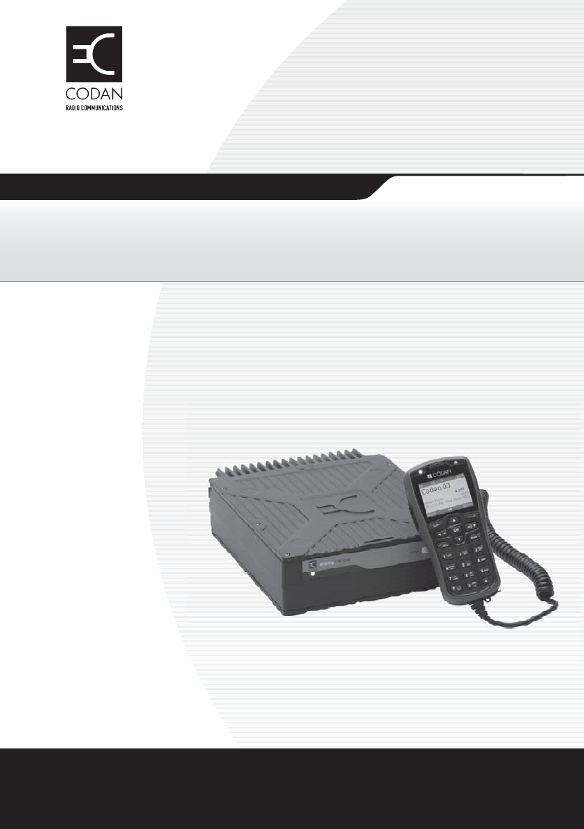
Figure 1: 2220 Handset
The 2220 Handset is a hand-held device that has a microphone, a
PTT button, a screen, navigation keys, and numeric keys. The
keypad enables you to control and configure the transceiver system
via the user interface. The handset and an external speaker connect
to the RFU via a special interface cable.
navigation and
software keys
Power key Emergency key
numeric keys
USB connector
screen
microphone
CALL SCAN
OK
1
TUNE FUNC MODE
FREE Rx
SEC
VS
VIEW
EASI
TAL K
ABC DEF
GHI JKL MNO
PQRS TUV WXYZ
23
456
789
0
PTT

INTRODUCTION
THE 2220 HANDSET
4ENVOY™ TRANSCEIVER GETTING STARTED GUIDE
The 2220 Handset is shipped from the factory with standard
functions pre-programmed to specific keys. The standard function
is written on the key in blue text. New user-defined functions may
be assigned to most of the keys.
Related links:
Keypad on page 8
Navigating the menu structure on page 31
INTRODUCTION
THE 2221 HANDSET
ENVOY™ TRANSCEIVER GETTING STARTED GUIDE 5
The 2221 Handset
The 2221 Handset is a control point for the Envoy™ Transceiver.
The user interface provides an icon-based menu structure for easy
operation of the transceiver. It has a condensed set of keys for use
in simpler communication scenarios.
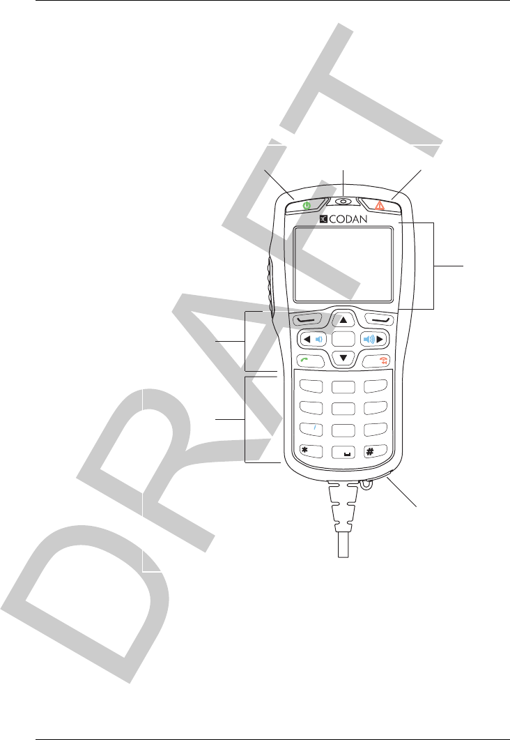
Figure 2: 2221 Handset
The 2221 Handset is a hand-held device that has a microphone, a
PTT button, a screen, and navigation keys. The navigation keys
enable you to operate the transceiver system via the user interface
using pre-defined profile information. Typically, this profile is
fully configured using the TPS system programmer. The handset
and an external speaker connect to the RFU via a special interface
cable.
CALL SCAN
OK
navigation and
software keys
Power key Emergency key
USB connector
microphone
screen
PTT

INTRODUCTION
THE 2221 HANDSET
6ENVOY™ TRANSCEIVER GETTING STARTED GUIDE
The 2221 Handset is shipped from the factory with standard
functions pre-programmed on the key, or in a list that is
accessed via the Functions icon ( ). New user-defined functions
may be assigned to this list.
Related links:
Keypad on page 8
Navigating the menu structure on page 31
INTRODUCTION
THE 2230 DESK CONSOLE
ENVOY™ TRANSCEIVER GETTING STARTED GUIDE 7
The 2230 Desk Console
The 2230 Desk Console is a control point for the Envoy™
Transceiver. The user interface provides an icon-based menu
structure for easy setup and operation of the transceiver. The desk
console is standard for a fixed station.
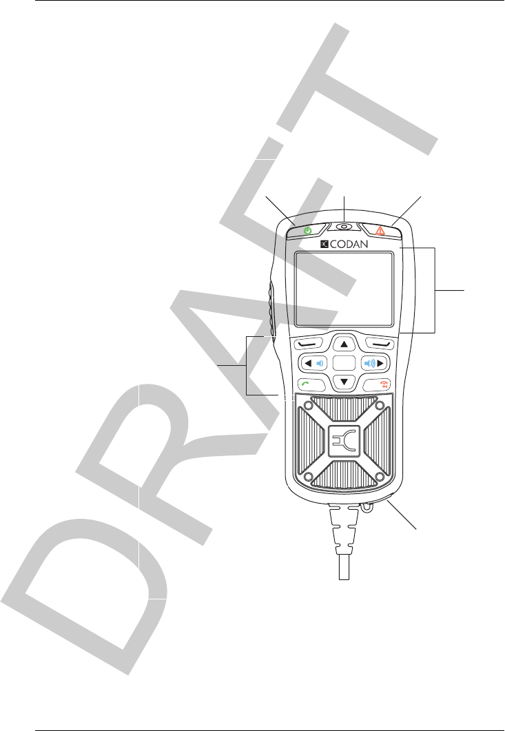
Figure 3: 2230 Desk Console
The 2230 Desk Console has an optional boom microphone, a
built-in speaker, a PTT button, a screen, navigation keys, function
keys, and numeric keys. The console also supports the use of
headphones, a foot-switched PTT device, and a separate hand
microphone with PTT. The keypad enables you to control and
configure the transceiver system via the user interface.
The 2230 Desk Console is shipped from the factory with standard
hot keys programmed to the numeric keys. The function that each
standard hot key performs is written on the numeric key in blue
text.
Related links:
Keypad on page 8
Navigating the menu structure on page 31
FUNC
ABC
2
Desk Console
F1 F2 F3
MODE
DEF
31
TUNE
FREE Rx
GHI
4
MNO
6
WXYZ
9
V/S
PQRS
7
EASI
TAL K
VIEW
0
SEC
TUV
8
JKL
5
SCAN
CALL
OK
speaker
boom microphone
function keys
Power key
Emergency key
numeric keys
PTT
screen
navigation and
software keys
INTRODUCTION
KEYPAD
8ENVOY™ TRANSCEIVER GETTING STARTED GUIDE
Keypad
Standard macros are programmed in the transceiver in the factory.
You can also create a macro and assign it to a hot key.
NOTE: For more information, see the Reference Manual.
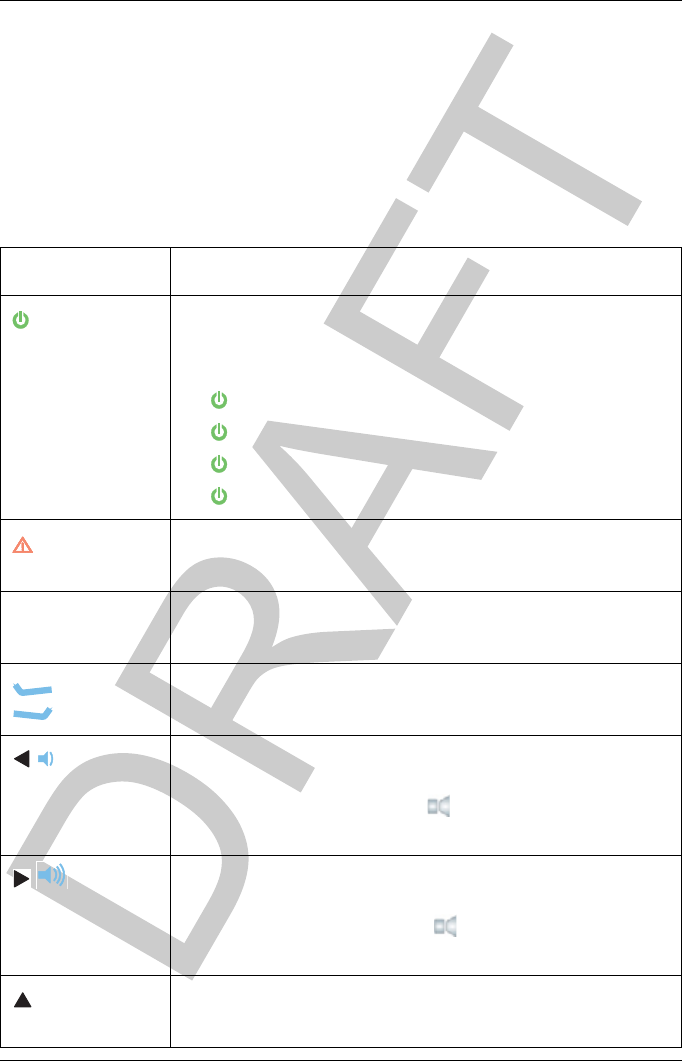
Table 1: Keys and their function
Key Function
Switches on the transceiver.
Switches off the transceiver (hold for 2 sec).
Performs a hot-key sequence with another key (hold + key):
• + 0 jumps to the Brightness screen
• + 2 toggles advanced view
• + 3 jumps to the Select Language screen (admin level)
• + SEC performs secure erase
Starts a chain call of all calls for the selected emergency
contact (hold for 2 sec).
PTT Press-to-talk.
Cancels out of editing and calls before they are connected.
Performs the function shown directly above the key in the
menu bar of the screen.
Scrolls left in a list of values.
Moves the cursor/highlight to the left.
Reduces the volume when the indicator is shown in the
menu bar of the screen.
Scrolls right in a list of values.
Moves the cursor/highlight to the right.
Increases the volume when the indicator is shown in the
menu bar of the screen.
Scrolls up in a list of entries.
Moves the highlight up a row.

INTRODUCTION
KEYPAD
ENVOY™ TRANSCEIVER GETTING STARTED GUIDE 9
Scrolls down in a list of entries.
Moves the highlight down a row.
OK Enters the submenu or list of entries represented by the
selected icon.
Toggles the selection of a check box.
Enters the virtual keypad in the user interface of a
2221 Handset.
CALL Starts the calling process by jumping to the call screen
(default behaviour).
Jumps to Contacts/Call History/Emergency Contacts/Last
Heard Log (hold for 2 sec).
SCAN Toggles scanning on and off.
Ends a call.
Deletes the character to the left of the cursor.
Deletes all characters (hold for 2 sec).
1TUNE Enters 1 in character-entry mode.
Tunes the antenna.
2FUNC Enters 2, a, b, c, A, B, C in character-entry mode.
Access the clarifier for the currently selected channel.
3MODE Enters 3, d, e, f, D, E, F in character-entry mode.
Selects the next allowed mode for the current channel.
4FREE Rx Enters 4, g, h, i, G, H, I in character-entry mode.
Accesses the free-tune receive function.
5Enters 5, j, k, l, J, K, L in character-entry mode.
Toggles the operating mode of a crosspatch, if connected.
Shows the firmware version of a crosspatch, if connected
(hold for 2 sec).
6Enters 6, m, n, o, M, N, O in character-entry mode.
Table 1: Keys and their function (cont.)
Key Function

INTRODUCTION
KEYPAD
10 ENVOY™ TRANSCEIVER GETTING STARTED GUIDE
7V/S Enters 7, p, q, r, s, P, Q, R, S in character-entry mode.
Toggles the type of mute selected.
8SEC Enters 8, t, u, v, T, U, V in character-entry mode.
Toggles secure mode on and off.
Enables you to enter a PIN for a secure session, or access
secure information (hold for 2 sec).
9Enters 9, w, x, y, W, X, Y in character-entry mode.
0VIEW Enters 0 or a space in character-entry mode.
Toggles between the channel screen and Contacts/Call
History.
EASITALK Enters a special character (repeated press, or hold for 2 sec).
Toggles Easitalk™ on or off.
Toggles character-entry mode.
Enables you to select the input language (hold for 2 sec).
Table 1: Keys and their function (cont.)
Key Function

INTRODUCTION
ACCESSING THE CD
ENVOY™ TRANSCEIVER GETTING STARTED GUIDE 11
Accessing the CD
To access the CD:
Place the CD in the CD drive of your computer.
You can view and search the Reference Manual and Getting
Started Guide using the Adobe® Reader® supplied on the
CD.

INTRODUCTION
STANDARDS AND ICONS
12 ENVOY™ TRANSCEIVER GETTING STARTED GUIDE
Standards and icons
The following standards and icons are used:
This typeface... Means...
Italic a cross-reference, text requiring emphasis, or variable
information
Bold a key on a computer keyboard
Bold a menu, submenu, tab, entry, a value in the user interface of
the control point, or key that you press on the control point
ACTION a hot key for a factory macro
NOTE: the text may be of interest to you
CAUTION: proceed with caution as your actions may lead to loss of
data, privacy or signal quality
WARNING: your actions may cause harm to yourself or the equipment

ENVOY™ TRANSCEIVER GETTING STARTED GUIDE 13
2Using the wizard
This section contains the following topics:
•Overview of the wizard on page 14
•Using the wizard on page 16
•Selecting a language on page 17
•Setting the time and date on page 17
•Setting the location of the desk console on page 18
•Adding a channel on page 19
•Entering a self address on page 21
•Adding a contact on page 22
•Selecting an antenna on page 29
•Selecting a peripheral device on page 30

USING THE WIZARD
OVERVIEW OF THE WIZARD
14 ENVOY™ TRANSCEIVER GETTING STARTED GUIDE
Overview of the wizard
The wizard is available if the transceiver:
• has not been programmed with a profile
• has a basic profile that has a common self address for the
default HF networks Selcall and CALM, and has one scan
table
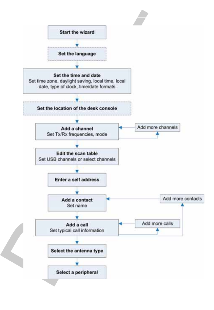
The wizard steps you through setting up information in the
transceiver so that it may be operated at a basic level.
USING THE WIZARD
OVERVIEW OF THE WIZARD
ENVOY™ TRANSCEIVER GETTING STARTED GUIDE 15
Figure 4: Steps in the wizard
USING THE WIZARD
USING THE WIZARD
16 ENVOY™ TRANSCEIVER GETTING STARTED GUIDE
Using the wizard
The wizard should start automatically when a new transceiver is
powered up for the first time.
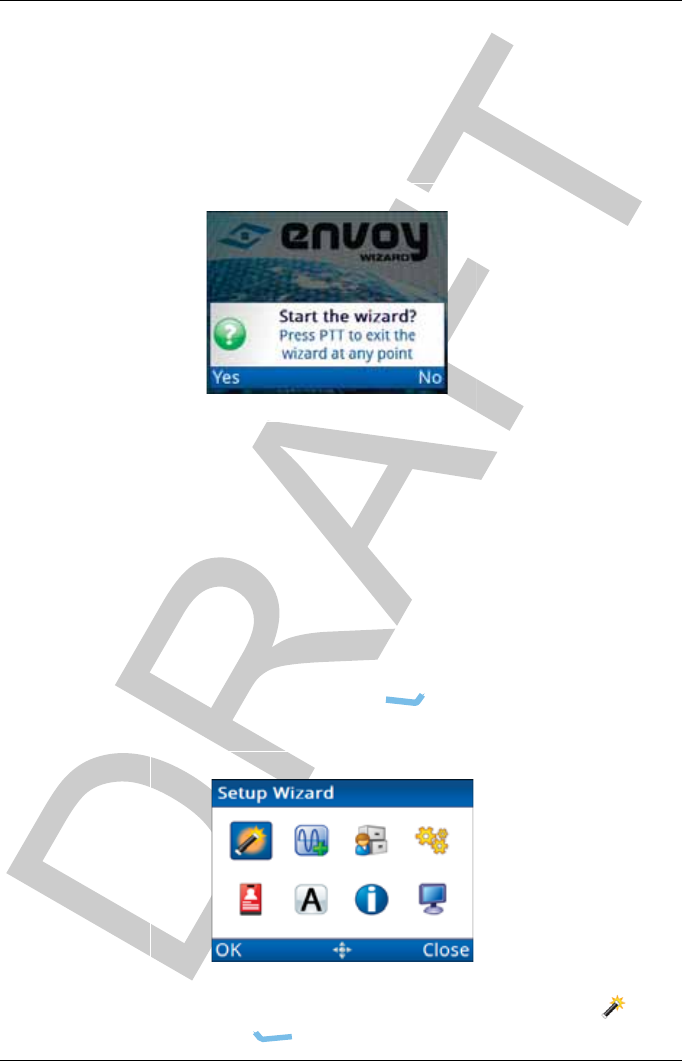
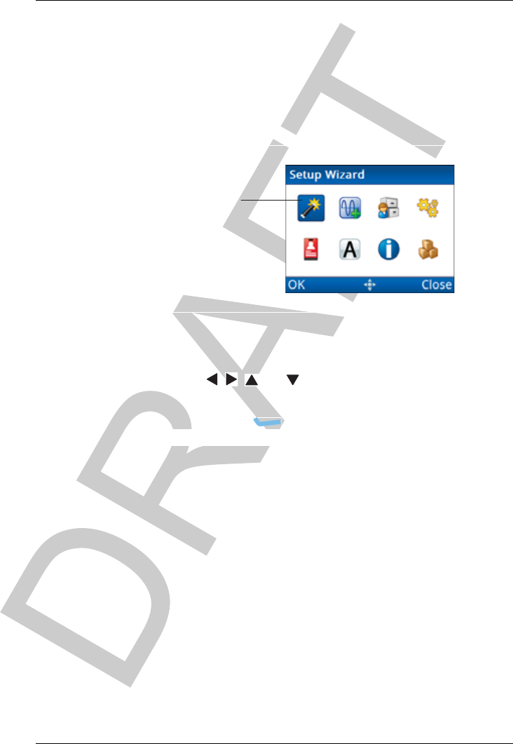
Figure 5: Wizard Startup screen
NOTE: If the wizard screen doesn’t launch automatically,
follow the instructions below. If your transceiver has
been profiled using TPS, the wizard may not be
available.
NOTE: For information on specific entries in the wizard,
please see the Reference Manual.
To use the wizard:
Press PTT, then press (Menu) to return to the top
level of the menu structure.
Check that the icon for the wizard is highlighted ( ), then
press (OK).

USING THE WIZARD
USING THE WIZARD
ENVOY™ TRANSCEIVER GETTING STARTED GUIDE 17
Press (Yes) to confirm that you want to start the
wizard.
If you want to bypass the wizard, press (No).
Selecting a language
NOTE: This step in the wizard is shown if you have multiple
languages available.
To select a language:
Press or to scroll to the language that you want to use
on the control point, then press OK.
Press (Save) to save the information.
Press (Yes) to confirm that you want to change the
language.
Setting the time and date
To set the time and date:
Press or to select the time zone that you want to use.
Press to move to the Daylight Saving entry.
Press or to select the time that you want to use.
Press to move to the Local Time entry.
Press to enter edit mode for the local time.
Press or to scroll to the value that you want to set, then
press to move to the next item.
Repeat this for minutes, seconds and AM/PM values.
Press (Save) to save the local time.
Press to move to the Local Date entry.
Press to enter edit mode for the local date.

USING THE WIZARD
USING THE WIZARD
18 ENVOY™ TRANSCEIVER GETTING STARTED GUIDE
Press or to scroll to the value that you want to set, then
press to move to the next item.
Repeat this for the day/month and year, as required.
Press (Save) to save the local date.
Press to move to the Clock entry.
Press or to select the type of clock that you want to use.
Press to move to the Time Format entry.
Press or to select the format that you want to use.
Press to move to the Date Format entry.
Press or to select the format that you want to use.
If you want to review the information that you have entered,
press or to move through the entries.
Press (Save) to save the information.
If you have not changed any of the time and date
information, press (Close).
Setting the location of the desk console
NOTE: This step in the wizard is shown if your control point
is a desk console.
To set the location of the desk console:
Press or to select the value that you want to use from
the following:
• If the desk console is connected to the transceiver
using cable 08-07205-00x, select Local.
• If the desk console is connected to the transceiver
using an Ethernet cable (08-07215-001), select
Remote.
Press (Save) to save the information.

USING THE WIZARD
USING THE WIZARD
ENVOY™ TRANSCEIVER GETTING STARTED GUIDE 19
Adding a channel
NOTE: This step in the wizard is shown if you are permitted
to add channels.
To add a channel:
Press (Yes) to add a channel, if required.
Enter the name that you want to use for the channel.
Press to move to the Tx entry.
Enter the transmit frequency (in kHz) that you want to use
for this channel.
Press to move to the Rx entry.
The Rx entry is automatically filled with the transmit
frequency.
Enter the receive frequency (in kHz), if required to be
different from the Tx frequency.
Press to move to the Mode entry.
To select a mode:
• Press to view the list of available modes.
• Press or to scroll to the mode that you want to
use, then press OK.
The check box contains a when the mode is
selected.
• Select other modes, as required.
NOTE: The modes that you select become the
allowed modes for this channel. In a
scan table, you can duplicate a channel
and select another of the allowed
modes.
•Press (Save).
If you want to review the information that you have entered,
press or to move through the entries.
Press (Save) to save the information.

USING THE WIZARD
USING THE WIZARD
20 ENVOY™ TRANSCEIVER GETTING STARTED GUIDE
Do one of the following:
• If you want to add another channel, press
(Yes), then repeat these steps.
• If you do not want to add another channel,
press (No).
The channels that you enter may be notionally grouped into
scan tables. A scan table enables you to manage how these
channels are scanned using one set of properties. The same
channel may be included in one or more scan tables. One or
more scan tables may be allocated to an HF network. The
same scan table may be allocated to different HF networks.
Do one of the following:
• If you want to add a scan table, press (Yes).
• If you do not want to add a scan table, press
(No), then continue from Entering a self address on
page 21.
Do one of the following:
• If you want to scan all of the channels in the
transceiver that have a USB mode, press
(Yes), then continue from Entering a self address on
page 21.
• If you want to choose the channels and modes that
you want to scan, press (No), then continue
from Adding channels to a scan table on page 20.
Adding channels to a scan table
To add channels to a scan table:
Press or to scroll to the channel that you want to add,
then press OK.
Press or to select the mode that you want to use.
Select more channels, as required.

USING THE WIZARD
USING THE WIZARD
ENVOY™ TRANSCEIVER GETTING STARTED GUIDE 21
Press (Save) to add these channel selections.
Continue from Entering a self address on page 21.
Entering a self address
A self address is used by other stations to call your station. For
example, if the self address of your station is 1234, operators at
other stations enter the address 1234 when they want to make a call
to you.
To enter a self address:
Enter the address that you want to use.
You can enter up to six digits.
NOTE: Addresses ending in 99 and 00 have a special
function in Selcall HF networks.
Press (Save) to save the information.
NOTE: The wizard automatically allocates this self
address to the default HF networks: Selcall
and CALM (if FED-STD-1045 ALE or
MIL-STD-188-141B ALE option is
installed).
Do one of the following:
• If you want to add a contact, press (Yes), then
continue from Adding a contact on page 22.
• If you do not want to add a contact, press (No),
then continue from Selecting an antenna on page 29.

USING THE WIZARD
USING THE WIZARD
22 ENVOY™ TRANSCEIVER GETTING STARTED GUIDE
Adding a contact
A contact is a person who you want to call, and for whom you want
to pre-define the method of calling them. You may be able to
contact the same person via a number of different methods. When
you set up the contact, you define each method as a separate call for
the contact.
NOTE: If you require more detail on adding a contact, see
Contacts on page 93.
To add a contact:
Enter the name that you want to use for the contact, then
press (Add Call).
The HF Network entry is highlighted.
The HF network defines the call system and self address that
is used by your station when the call is made. For example,
if you want to select a channel for the call, use a Selcall HF
network. If you want the transceiver to automatically select
a channel for the call, use a CALM HF network.
Press or to select the HF network that you want to use.
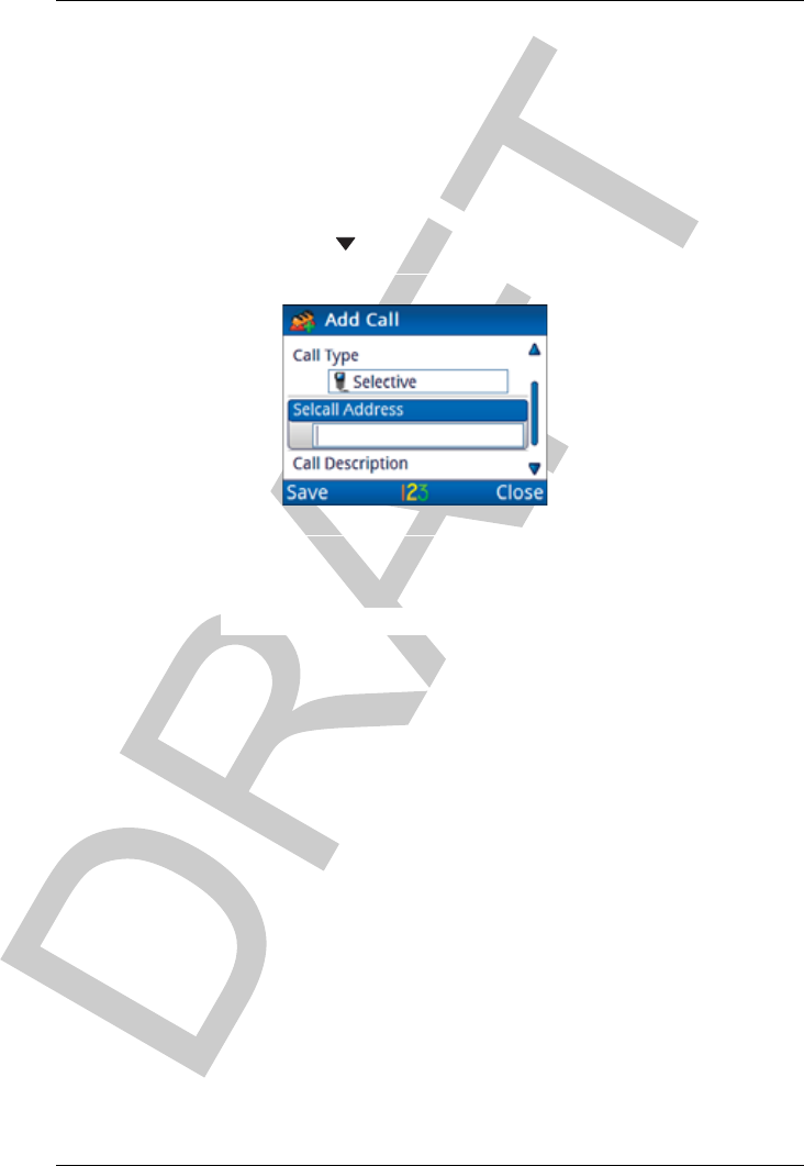
Press to move to the Call Type entry.
Press or to select the call type that you want to use.
NOTE: The call type that you select affects
information that you can enter for the
remainder of this call.
If you are adding:
• a Selective, Channel Test, Emergency, Get Position
or Send Position call Adding a simple call on page 23
• a Message call Adding a Message call on page 24
• a Phone call Adding a Phone call on page 26
• a Get Status call Adding a Get Status call on page 27
USING THE WIZARD
USING THE WIZARD
ENVOY™ TRANSCEIVER GETTING STARTED GUIDE 23
Adding a simple call
A simple call is a call that requires an address only at this stage of
the definition process.
To continue with adding a Selective, Channel Test, Emergency,
Get Position or Send Position call:
Press to move to the Selcall|ALE Address entry.
Enter the address of the station that you want to call.
Continue from Completing the contact on page 28.
USING THE WIZARD
USING THE WIZARD
24 ENVOY™ TRANSCEIVER GETTING STARTED GUIDE
Adding a Message call
To continue with adding a Message call:
Press to move to the Selcall|ALE Address entry.
Enter the address of the station that you want to call.
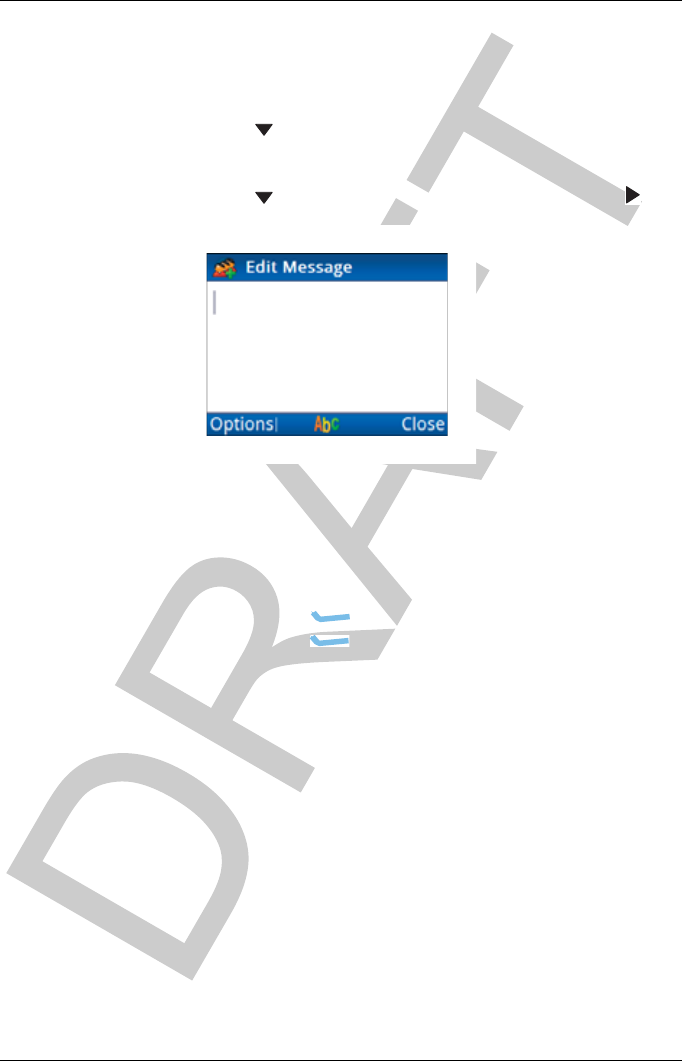
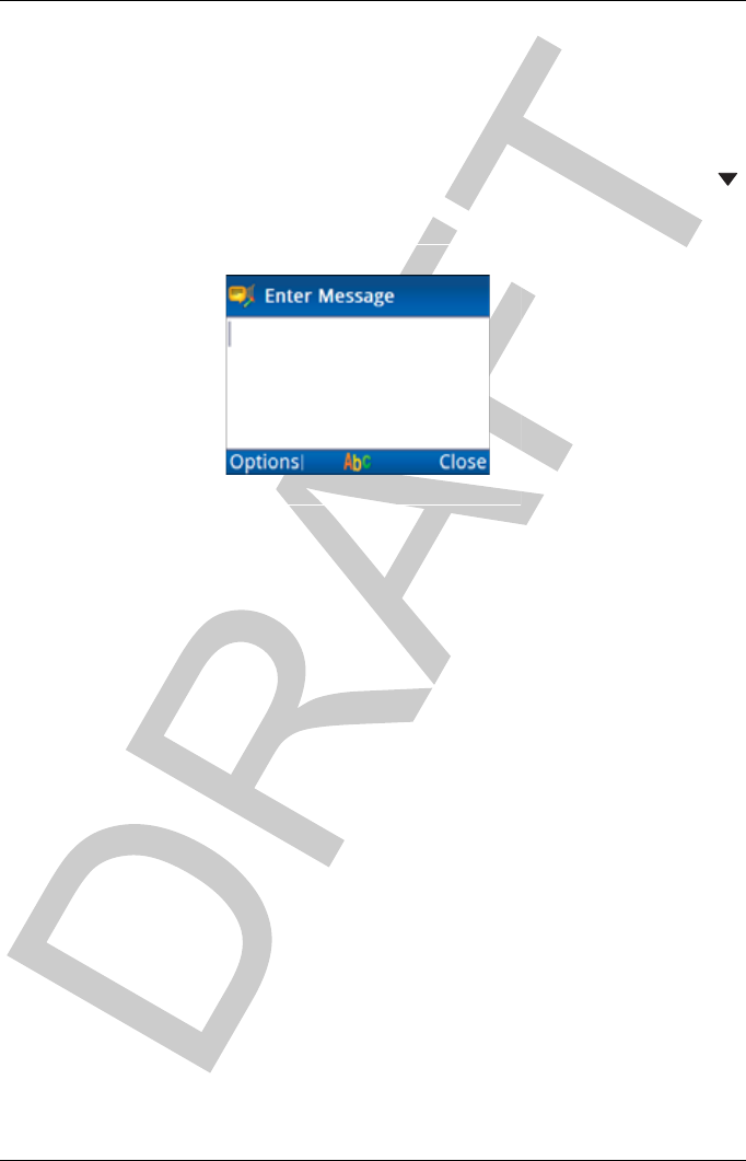
Press to move to the Message entry, then press .
If you want to enter a message:
• Start typing the message.
NOTE: Press OK to start a new line, if
required.
• Press (Options), scroll to OK, then
press (Select) to add the message to the call.
USING THE WIZARD
USING THE WIZARD
ENVOY™ TRANSCEIVER GETTING STARTED GUIDE 25
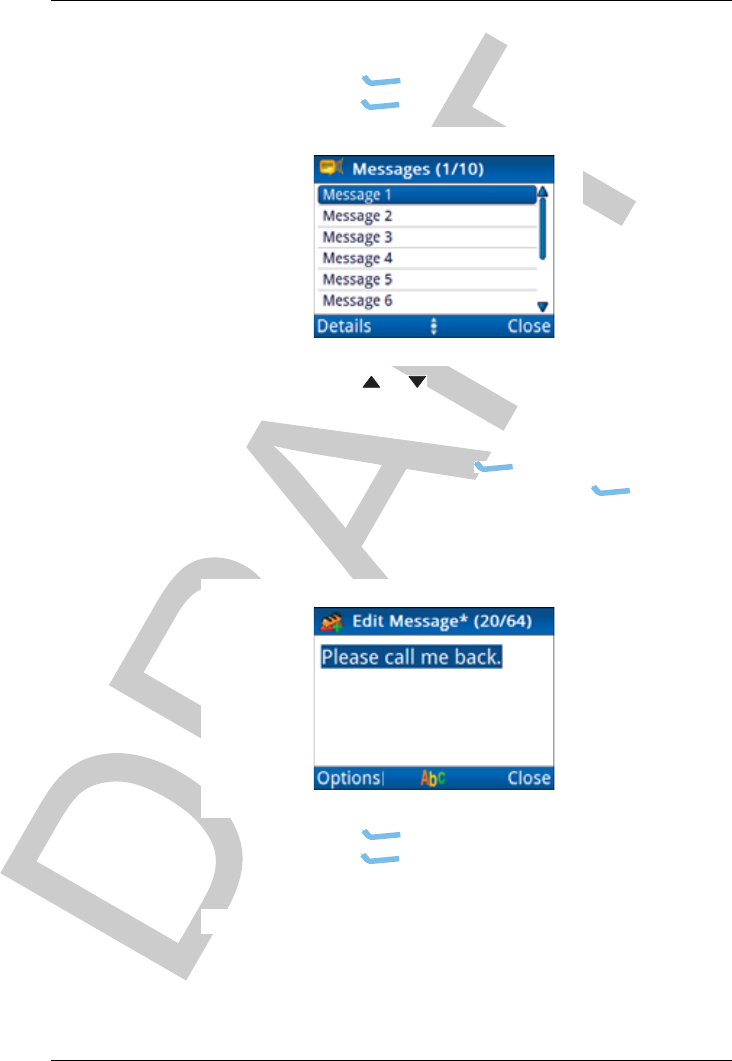
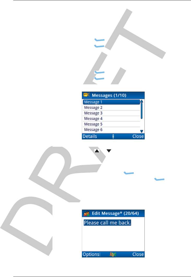
If you want to select a message from a list of stored
messages:
•Press (Options), scroll to Stored, then
press (Select).
• Press or to scroll to the message that you want
to use.
NOTE: If you want to view the message,
press (Details) to view the
message, then press (Close).
•PressOK to select the message.
• Edit the message, if required.
•Press (Options), scroll to OK, then
press (Select).
Continue from Completing the contact on page 28.

USING THE WIZARD
USING THE WIZARD
26 ENVOY™ TRANSCEIVER GETTING STARTED GUIDE
Adding a Phone call
To continue with adding a Phone call:
Press to move to the Phone Number entry.
Enter the phone number.
Continue from Completing the contact on page 28.
USING THE WIZARD
USING THE WIZARD
ENVOY™ TRANSCEIVER GETTING STARTED GUIDE 27
Adding a Get Status call
To continue with adding a Get Status call:
Press to move to the Selcall|ALE Address entry.
Enter the address of the station that you want to call.
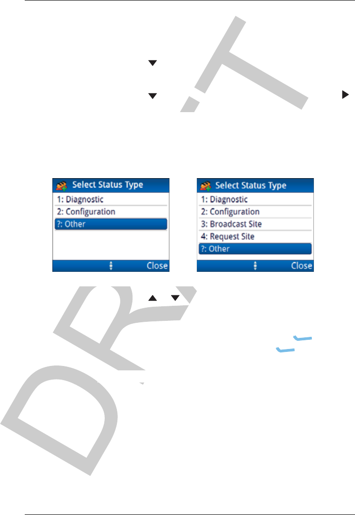
Press to move to the Status Type entry, then press .
Press or to scroll to the status type that you want to
use, then press OK.
If you selected ?: Other as the status type, enter the
text/command that you want to send, press
(Options), scroll to Save, then press (Select).
Continue from Completing the contact on page 28.
Selcall HF network ALE/CALM HF network
ALE Site Manager:
Auto
Manual
Restricted

USING THE WIZARD
USING THE WIZARD
28 ENVOY™ TRANSCEIVER GETTING STARTED GUIDE
Completing the contact
To finish entering the information required for the contact:
Press to move to the Call Description entry.
By default, the call type is entered as the call description.
Enter the description that you want to use for this call.
Press (Save) to save the information.
If you want to add another call for the contact, press
(Yes), then repeat the steps for adding a call.
If you do not want to add another call, press (No).
If you want to add another contact, press (Yes), then
repeat the steps for adding a contact.
If you do not want to add another contact, press (No).
Do one of the following:
• If you want to select an antenna, continue from
Selecting an antenna on page 29.
• If you do not want to select an antenna, continue
from Selecting a peripheral device on page 30.

USING THE WIZARD
USING THE WIZARD
ENVOY™ TRANSCEIVER GETTING STARTED GUIDE 29
Selecting an antenna
Each type of antenna has a specific requirement for tuning, and the
transceiver uses a different protocol for each one. You must select
the type of antenna that is used in your station so that the
transceiver knows how to tune the antenna. Some antennas, such as
broadband antennas, do not require tuning.
To select an antenna:
Do one of the following:
• Press or to scroll to the antenna type that you
want to use, then press OK.
•Press (Close), then continue from Selecting a
peripheral device on page 30.
Press (Save) to save the information.
Do one of the following:
• If you want to connect an accessory to the 15-way
port of the RFU, press (Yes), then continue
from Selecting a peripheral device on page 30.
• If you do not want to connect an accessory,
press (No), then press OK to close the wizard.

USING THE WIZARD
USING THE WIZARD
30 ENVOY™ TRANSCEIVER GETTING STARTED GUIDE
Selecting a peripheral device
When you select the peripheral device from the list, the transceiver
automatically sets these properties.
NOTE: Codan peripheral devices are listed by their type
number, for example, 3031 Crosspatch. The type
number for a Codan device is located on the front or
serial number escutcheon.
To select a peripheral device:
Press or to scroll to the type of peripheral device that
is attached to the connector, then press OK.
If there are settings that you can change to optimise this
peripheral for your requirements, is shown to the right of
the peripheral name when it is selected.
If you want to change settings for the peripheral, press to
see the list of entries that you may change.
If you change the value of an entry for a peripheral device
from the default value, is shown next to the title of the
entry.
Press (Save) to automatically update settings for
correct operation of the connected peripheral device.
Press OK to close the wizard.
If you added a peripheral device, restart your transceiver to
activate the new settings.

ENVOY™ TRANSCEIVER GETTING STARTED GUIDE 31
3Navigating the menu
structure
This section contains the following topics:
•The basic menu structure on page 32
•Navigating the menu structure on page 34
•Overview of basic and advanced views on page 36
•Finding a word or value on page 38
•Selecting an icon on page 41
•Selecting a function from the menu bar on page 42
•Entering text in a field on page 44
•Selecting a value from a list on page 49
•Selecting/deselecting a check box on page 50
•Moving a slider on page 51
•Changing the order of items in a list on page 52
•Saving your changes on page 53
NAVIGATING THE MENU STRUCTURE
THE BASIC MENU STRUCTURE
32 ENVOY™ TRANSCEIVER GETTING STARTED GUIDE
The basic menu structure
The menu structure comprises a main menu and a series of
submenus that are accessed via the main menu. Each menu and
submenu is represented by an icon. Some icons provide direct
access to an input/view screen, while other icons provide a list of
entries for the menu.
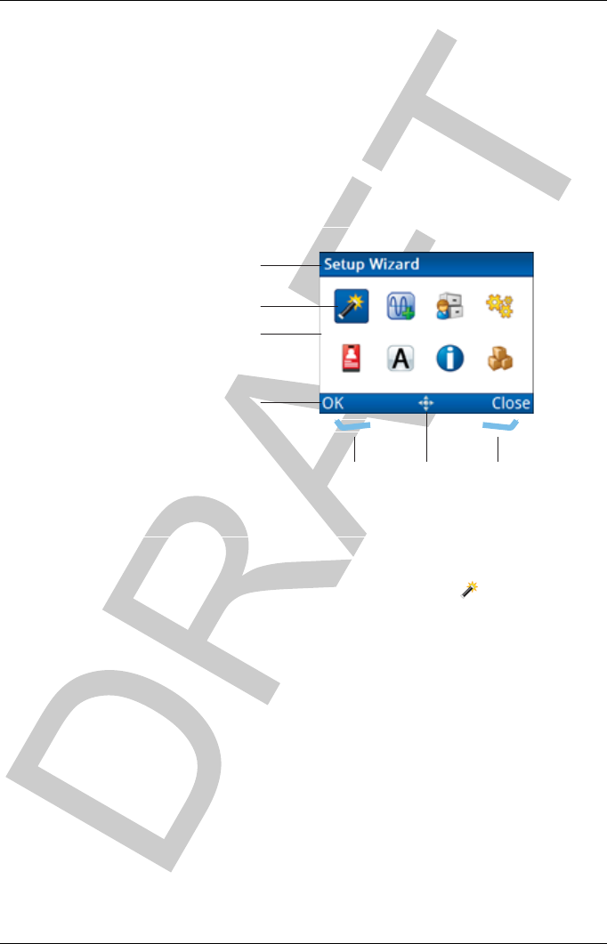
Figure 6: Typical menu screen
When an icon is highlighted, the name of the icon is shown in the
title bar of the screen. For example, when the icon is
highlighted, Setup Wizard is shown in the title bar.
title bar
menu bar
icon area
highlighted icon
navigation
indicator
left
software
key
right
software
key
NAVIGATING THE MENU STRUCTURE
THE BASIC MENU STRUCTURE
ENVOY™ TRANSCEIVER GETTING STARTED GUIDE 33
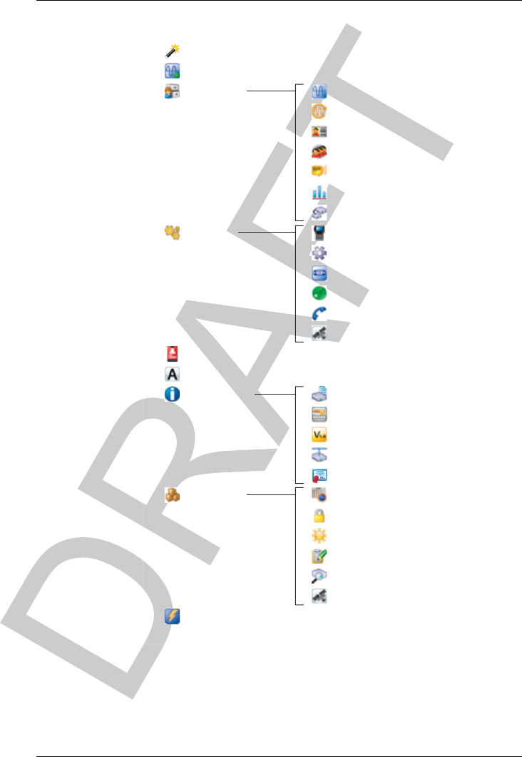
Figure 7: Menu structure (user level, basic view)
The menu items may contain further submenus and lists of entries.
Each entry either has specific values from which you may choose,
or you may enter the information required.
Channels
Scan Tables
HF Networks
User Data
Settings Control Point
Configuration
Information
General
Add Channel
Setup Wizard
Contacts
Messages
Modes
Peripherals
Admin Login/Logout
Advanced View
Device Information
GPS
Time and Date
Connectors
Scan
Calling
GPS
Version
IP Connectivity
Licence
Secure
Brightness
Self Tests
Find RFU
Option Password
Functions
(2221 only)
NAVIGATING THE MENU STRUCTURE
NAVIGATING THE MENU STRUCTURE
34 ENVOY™ TRANSCEIVER GETTING STARTED GUIDE
Navigating the menu structure
The menu structure comprises a main menu and a series of
submenus that are accessed via the main menu. Navigation keys
enable you to highlight an icon, then press OK to select that menu.
You can continue drilling down through the menu structure in this
way. At the lowest level of the menu structure there is either an
input/view screen, or a list of entries.
Navigation is available when the navigation indicator is shown in
the menu bar at the bottom of the screen.
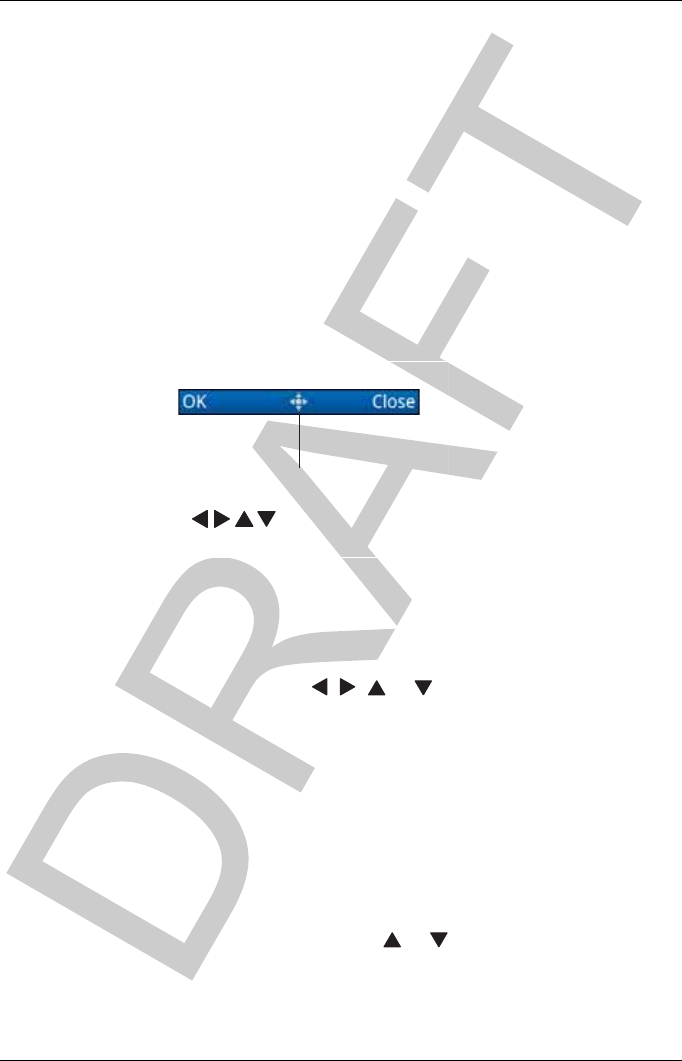
Figure 8: Navigation indicator showing navigation keys
that may be used
To navigate the menu structure:
To move down through the menu structure:
• Press , , or to highlight the icon that you
want to select.
The name of the icon appears in the title bar of the
screen.
• Press OK.
• Continue moving down through the menu structure
by highlighting the icon that you want, then
pressing OK.
To move through a list of entries at the lowest level of the
menu structure, press or .
navigation
indicator
( keys may be used)

NAVIGATING THE MENU STRUCTURE
NAVIGATING THE MENU STRUCTURE
ENVOY™ TRANSCEIVER GETTING STARTED GUIDE 35
To go to the top level in the menu structure, do one of the
following:
• Press PTT to exit to the channel screen, then
press (Menu) to enter the top level of the menu
structure.
• Press to return to the top level of the menu
structure, one level at a time.

NAVIGATING THE MENU STRUCTURE
OVERVIEW OF BASIC AND ADVANCED VIEWS
36 ENVOY™ TRANSCEIVER GETTING STARTED GUIDE
Overview of basic and advanced views
There are two views of information in the user interface of the
control point: basic and advanced. The contents of basic and
advanced views are pre-determined and cannot be changed.
Basic view
Basic view provides a condensed view of the user interface, and
typically the view at which the control point is operated. When you
power up the transceiver, the control point enters basic view. Basic
view is indicated by the absence of an advanced view indicator in
the menu bar.
Figure 9: Basic view (no advanced view indicator)
Basic view provides access to items that are likely to be changed on
a regular basis, or the user may want to change to suit their
preferences for the day-to-day operation of the transceiver. The
user can switch to advanced view to access items that they may
want to change occasionally. The user should switch back to basic
view to simplify the view of information presented on the screen of
the control point.
Advanced view
Advanced view provides access to additional settings that may
need to be changed occasionally, but are not required in the
day-to-day operation of the transceiver. Generally, the control
point of the transceiver is in basic view so you must switch to
advanced view. Advanced view is indicated by the presence of the
advanced view indicator in the menu bar.
NAVIGATING THE MENU STRUCTURE
OVERVIEW OF BASIC AND ADVANCED VIEWS
ENVOY™ TRANSCEIVER GETTING STARTED GUIDE 37
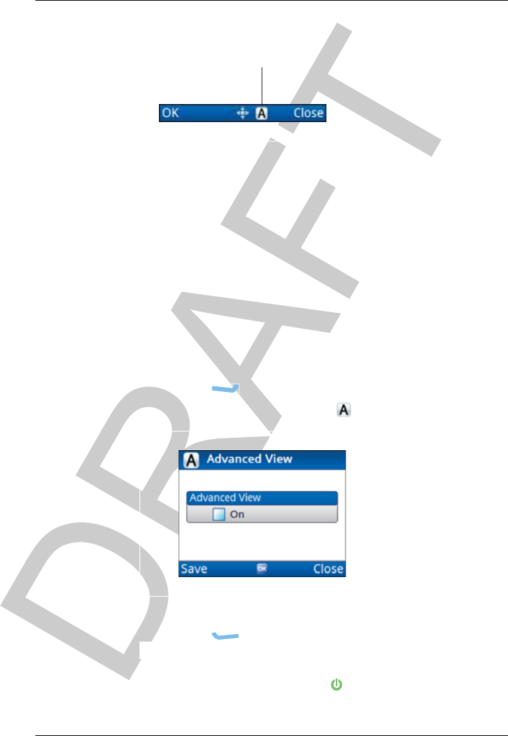
Figure 10: Advanced view
Switching between basic and advanced views
The user can switch between basic and advanced views to either:
• simplify the user interface of the control point (basic view),
or
• access advanced settings that they are permitted to change
(advanced view)
To switch between views:
Press until the main menu screen is shown.
From the main menu, select (Advanced View).
Press OK to toggle advanced view on or off as required.
Press (Save).
NOTE: You can also use the + 2 hot-key sequence to place
the user interface into advanced view.
advanced view
indicator

NAVIGATING THE MENU STRUCTURE
FINDING A WORD OR VALUE
38 ENVOY™ TRANSCEIVER GETTING STARTED GUIDE
Finding a word or value
The quickest way to find an entry or a value in the user interface of
the control point is to use the Find function, which is available via
the key when the icon selected contains submenus or lists of
entries. The feature searches for the sequence of characters (letter,
numbers, or a combination of both) that you enter.
NOTE: The Find function only searches on words and values
that are visible to the operator at the current view and
level of access.
NAVIGATING THE MENU STRUCTURE
FINDING A WORD OR VALUE
ENVOY™ TRANSCEIVER GETTING STARTED GUIDE 39
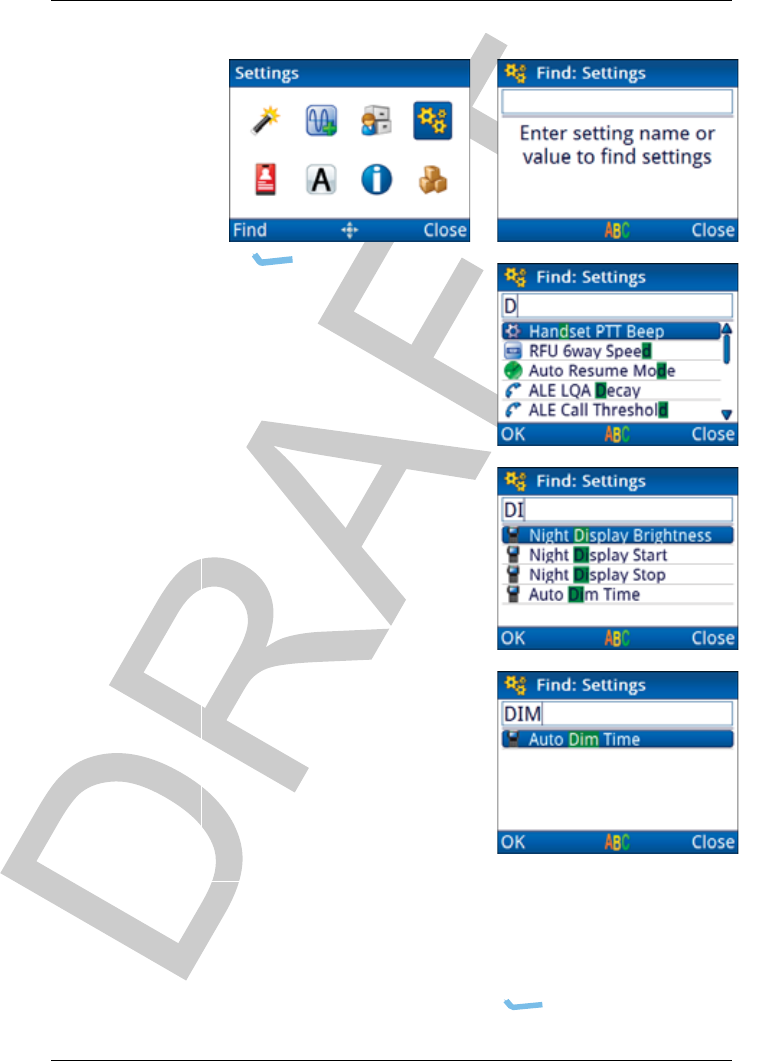
Figure 11: Find function
To find a word or value:
Highlight the icon that represents the highest level in which
you want to search, then press (Find).

NAVIGATING THE MENU STRUCTURE
FINDING A WORD OR VALUE
40 ENVOY™ TRANSCEIVER GETTING STARTED GUIDE
NOTE: If you select the icon by pressing OK, you
will enter that menu level. If you do not want
to search at the lower level, press
(Close) to return to the higher level, then
press (Find) again.
Enter the letter and/or number on which you want to search.
Any entries or values that contain the character you have
entered are shown in a list, with the character highlighted.
NOTE: You may have to scroll through the list to
view all of the results.
Enter more characters to refine your search.
The icon that is shown with each item in the list indicates the
location of the information. For example, if appears next
to the item, then it is located in Channels. If there is
another item with next to it, then it is located in HF
Networks.
Scroll to the entry or value that you want to select.
Press OK.
You are taken to the entry, or the name level of the user data
containing the character.
NAVIGATING THE MENU STRUCTURE
SELECTING AN ICON
ENVOY™ TRANSCEIVER GETTING STARTED GUIDE 41
Selecting an icon
The top levels of the menu structure are represented by icons. In
order to enter the menu represented by the icon, you need to select
the icon.
Figure 12: Highlighted icon
To select an icon:
Use , , and to highlight the icon that you want to
select.
Press OK or (OK) to select the icon.
highlighted icon
NAVIGATING THE MENU STRUCTURE
SELECTING A FUNCTION FROM THE MENU BAR
42 ENVOY™ TRANSCEIVER GETTING STARTED GUIDE
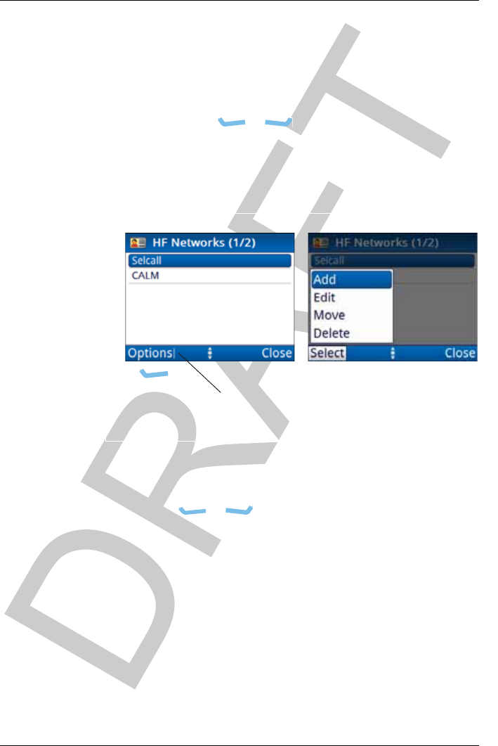
Selecting a function from the menu bar
The menu bar at the bottom of the screen provides varying
functions, depending on the context. You can select a function
directly, or activate a pop-up from the menu bar by pressing the
corresponding key ( or ). A vertical line next to the text
indicates that there are a number of choices from which to choose.
Typically, you can add, edit, move, delete, save, duplicate, and
clear items specific to your current location in the user interface.
Figure 13: Functions on the menu bar
To select a function from the menu bar:
Press or , corresponding to the function that you
want to select.
If the function in the menu bar does not have a vertical line
next to it, the function is performed immediately.
If the function in the menu bar has a vertical line next to it,
a pop-up is shown.
indicates that several
functions may be selected

NAVIGATING THE MENU STRUCTURE
SELECTING A FUNCTION FROM THE MENU BAR
ENVOY™ TRANSCEIVER GETTING STARTED GUIDE 43
If a pop-up of available functions is shown:
• Press or to scroll to the function that you want
to select.
•Press (Select).
The function is performed.
NAVIGATING THE MENU STRUCTURE
ENTERING TEXT IN A FIELD
44 ENVOY™ TRANSCEIVER GETTING STARTED GUIDE
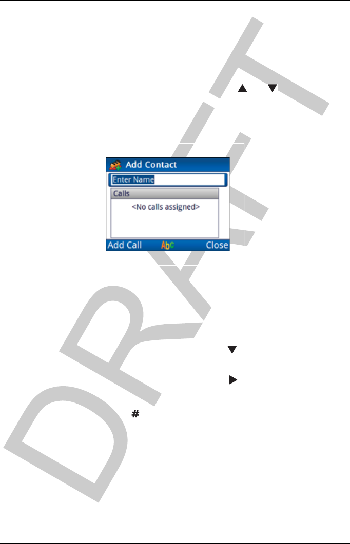
Entering text in a field
You may need to enter text into a field within an entry. This may
be a name given to some user data, or it may be a specific value,
such as a frequency. When you first enter an editable text field,
either by selecting a menu or using the and navigation keys,
any existing text that you can edit is highlighted. You can use this
text, edit this text, or delete this text and enter new text.
Figure 14: Example of an editable text field
To enter text in a field:
Navigate to a field in which you can edit text.
Do one of the following:
• To use this text, press .
• To delete this text, start entering new text.
• To edit this text, press to place the cursor at the
end of the text.
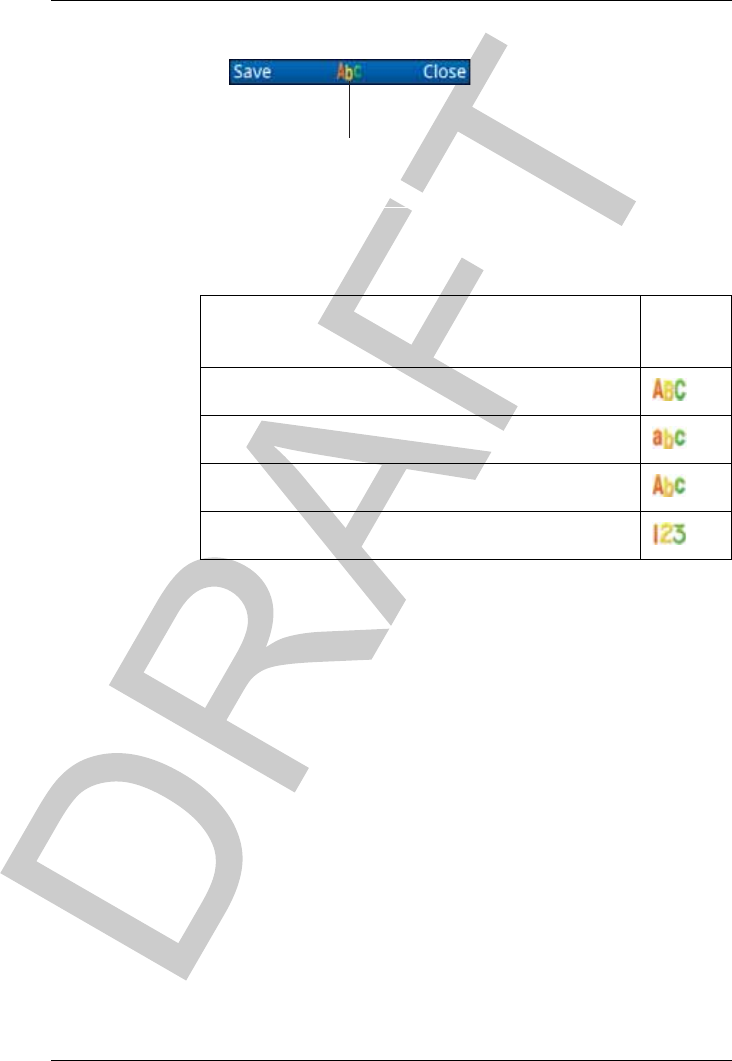
Press repeatedly to select the character-entry mode that
you want to use.
The indicator for the character-entry mode is shown in the
centre of the menu bar.
NAVIGATING THE MENU STRUCTURE
ENTERING TEXT IN A FIELD
ENVOY™ TRANSCEIVER GETTING STARTED GUIDE 45
Figure 15: Character-entry mode indicator
Table 2: Character-entry mode
Character-entry mode
Indicat
or
All upper-case letters
All lower-case letters
Leading-capital letters
Numbers
character-entry mode
indicator

NAVIGATING THE MENU STRUCTURE
ENTERING TEXT IN A FIELD
46 ENVOY™ TRANSCEIVER GETTING STARTED GUIDE
Do any of the following:
• Press or to move the cursor to the point at
which you want to enter text.
• Press to delete text to the left of the cursor.
•Hold to delete the whole entry.
• Press the key on the keypad that corresponds to the
letter that you want to enter.
For example, if you want to enter the letter E, press 3
twice.
After a brief pause, the cursor moves to the next
space, ready to enter another character.
NOTE: If you are in a letter-entry mode and
want to enter a number, hold the key
corresponding to the number that you
want to enter.
Press to move to the next entry.
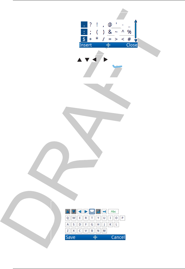
Entering special characters
You can enter special characters in messages and names, and in
addresses of stations that you call.
NOTE: If the FED-STD-1045 ALE/CALM option or
MIL-STD-188-141B ALE option is installed in your
transceiver, the key may be used to enter the
global ALL address syntax (@?@) or special ALE
addressing characters easily.
To enter a special character:
Press or to move the cursor to the point where you
want to insert a special character.
Press to cycle through the available choices or hold to
see the available special characters.
NAVIGATING THE MENU STRUCTURE
ENTERING TEXT IN A FIELD
ENVOY™ TRANSCEIVER GETTING STARTED GUIDE 47
Depending on the context, you can select from:
Press , , or to highlight the character that you
want to use, then press (Insert).
Repeat as required.
Entering text in the 2221 Handset
The 2221 Handset does not have alphanumeric keys, however, you
can still enter text into fields within the user interface.
CAUTION: This process describes how to enter text into an entry
field using the virtual keypad, then save the text back
to the entry. At this point, the change to the entry
itself has not been saved. Descriptions of processes
in this document continue from the change to the
entry.
To enter text:
Navigate to an entry in which you can enter text, then
press OK to see the virtual keypad.

NAVIGATING THE MENU STRUCTURE
ENTERING TEXT IN A FIELD
48 ENVOY™ TRANSCEIVER GETTING STARTED GUIDE
Press , , or to move the highlight to the character
that you want to select, then press OK.
If you want to change case, enter a number, or enter a
special character, scroll to , then press OK.
Continue entering text in this manner.
Press (Save) to save the information.
You are returned to the entry.
NAVIGATING THE MENU STRUCTURE
SELECTING A VALUE FROM A LIST
ENVOY™ TRANSCEIVER GETTING STARTED GUIDE 49
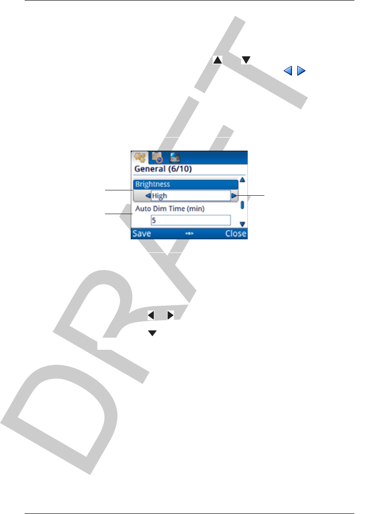
Selecting a value from a list
When you select an entry that has a list of values, either by
selecting an icon or using the and navigation keys, the field
is highlighted to show that it can be edited, and / indicators
appear on one or both sides of the field to show that multiple values
are available.
Figure 16: List of entries, with and without focus
To select a value from a list:
Navigate to an entry in which you can select a value.
Press or to select the value that you want to use.
Press to move to the next entry.
entry with focus
entry without focus
multiple values available
NAVIGATING THE MENU STRUCTURE
SELECTING/DESELECTING A CHECK BOX
50 ENVOY™ TRANSCEIVER GETTING STARTED GUIDE
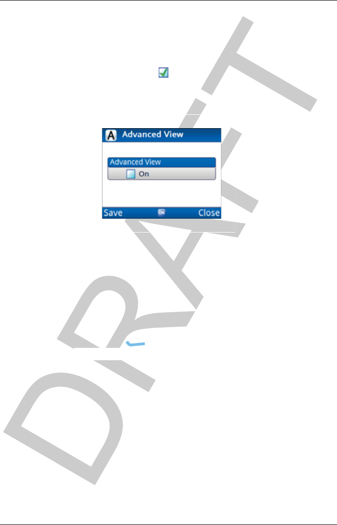
Selecting/deselecting a check box
There are some entries in the menu structure that require you to
enable or disable a particular feature via a check box. When the
check box contains a , the feature is enabled. If the check box is
clear, the feature is disabled.
Figure 17: Entry with a check box
To select or deselect a check box:
Highlight the entry.
Press OK to toggle the check box as selected or deselected.
When the check box is selected, the item is enabled. When
the check box is clear, the item is disabled.
Press (Save) to save the information.
NAVIGATING THE MENU STRUCTURE
MOVING A SLIDER
ENVOY™ TRANSCEIVER GETTING STARTED GUIDE 51
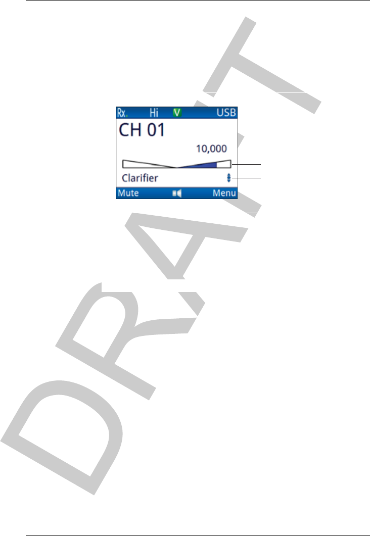
Moving a slider
Some values in the user interface of the control point are
represented by a slider.
Figure 18: A slider value
To move a slider:
Press any of the navigation keys suggested in the navigation
key indicator to adjust the slider.
slider
navigation key indicator

NAVIGATING THE MENU STRUCTURE
CHANGING THE ORDER OF ITEMS IN A LIST
52 ENVOY™ TRANSCEIVER GETTING STARTED GUIDE
Changing the order of items in a list
In some areas of the control point, you are able to change the order
in which the items appear, which impacts how the item is viewed,
or when each item may be used. For example, you may change the
order in which the channels, scan tables, HF networks, contacts,
phone links, and NETs are listed so that you don’t have to scroll to
the item to select it. In areas where the order is important, such as
NET members, you can move the items into the preferred response
order.
To change the order of items in a list:
Highlight the item that you want to move.
Press (Options), scroll to Move, then press
(Select).
Press or to move the item to the new position in the
list, then press (Place).
NAVIGATING THE MENU STRUCTURE
SAVING YOUR CHANGES
ENVOY™ TRANSCEIVER GETTING STARTED GUIDE 53
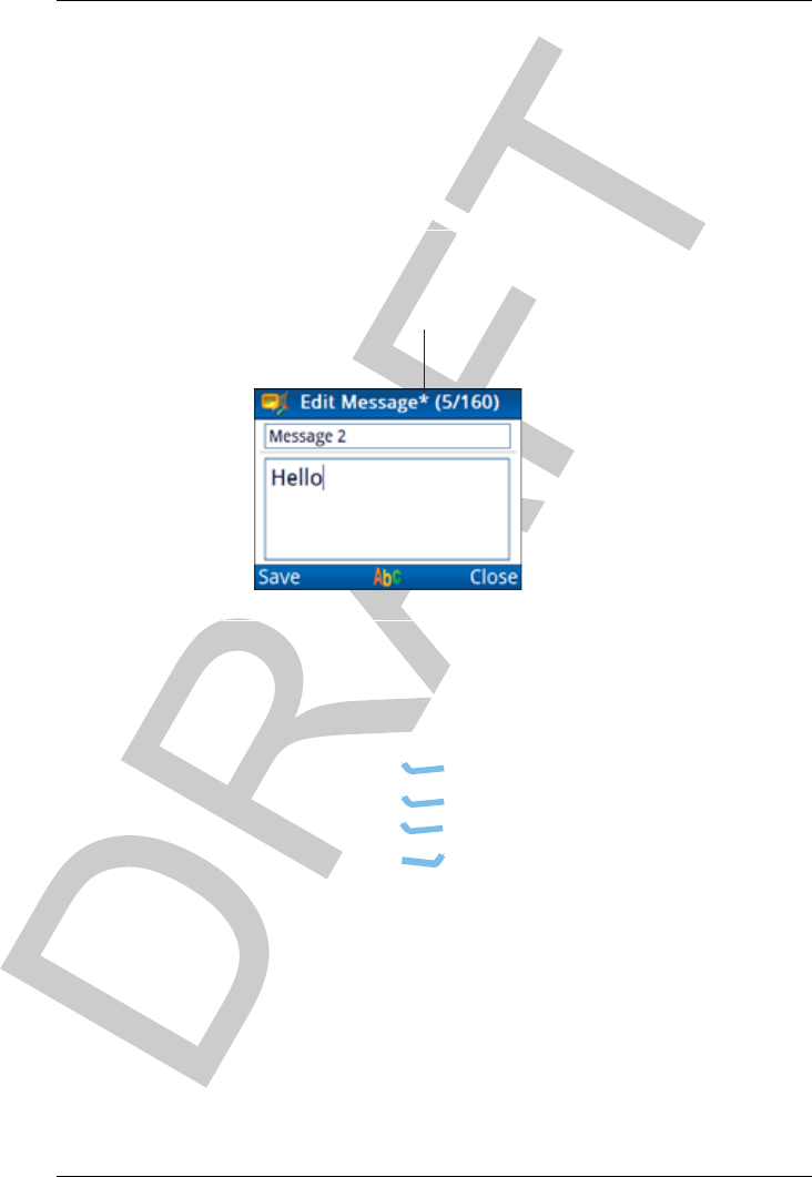
Saving your changes
When information in an entry has been changed, either by editing
existing text or selecting a different value from a list, an asterisk is
added to the title of the screen.
Figure 19: Screen that has changes to be saved
To save changes:
Do one of the following:
•Press (Save).
•Press (Options), scroll to Save, then
press (Select).
•Press (Close) to discard the changes.
asterisk indicates
that changes
have been made

NAVIGATING THE MENU STRUCTURE
SAVING YOUR CHANGES
54 ENVOY™ TRANSCEIVER GETTING STARTED GUIDE
This page has been left blank intentionally.

ENVOY™ TRANSCEIVER GETTING STARTED GUIDE 55
4Structure of
information
This section contains the following topics:
•Structure of user information on page 56
•Structure of contact and call information on page 58

STRUCTURE OF INFORMATION
STRUCTURE OF USER INFORMATION
56 ENVOY™ TRANSCEIVER GETTING STARTED GUIDE
Structure of user information
Information in the Envoy™ Transceiver is stored like blocks in a
building. Basic blocks are populated with information first, then
these blocks, along with different blocks, are assembled into larger
blocks. Ultimately, one of the top-level blocks is used to make a
call.
The most basic block is a frequency. A frequency is combined with
a mode, say USB or LSB, and a name to become a channel.
Channels may be grouped into scan tables. Scan tables may be
allocated to HF networks. An HF network defines the call system
by which a call is made.
Further blocks may be assembled for the convenience of the user.
A contact stores information on the typical calls that can be made
to a person. Each call is defined by the HF network and the call
type.
How these blocks are assembled is up to the system administrator.
There is, of course, finer detail that needs to be included, however,
the basic structure of information in the transceiver is shown in
Figure 20.

STRUCTURE OF INFORMATION
STRUCTURE OF USER INFORMATION
ENVOY™ TRANSCEIVER GETTING STARTED GUIDE 57
Figure 20: Basic structure of information in the Envoy™
Transceiver
Channels
HF network
Call system (RFDS)
Self address
Selected scan tables
HF network
Call system (Selcall)
Self address
Global (all channels)
HF network
Call system (ALE)
Self address
Selected scan tables
Scan table 1
Selected channels
Scan table 2
Selected channels

STRUCTURE OF INFORMATION
STRUCTURE OF CONTACT AND CALL INFORMATION
58 ENVOY™ TRANSCEIVER GETTING STARTED GUIDE
Structure of contact and call
information
A contact holds information on calls that you make to a particular
person. You may have several methods of calling the same person.
Each method that you use is bundled into a call for that contact. The
basic building blocks that you require to define a call to a contact
is the HF network that will be used, the type of call that you want
to make, and the address or telephone number at which the person
will answer the call. The basic structure of call information in a
contact is shown in Figure 21.
Figure 21: Structure of call information for a contact in the
Envoy™ Transceiver
Contact
HF network
Call system (RFDS)
Self address
Selected scan tables
HF network
Call system (Selcall)
Self address
Global (all channels)
HF network
Call system (ALE)
Self address
Selected scan tables
Available HF networks
Call 1
HF network (RFDS)
Call type (RFDS)
Call 2
HF network
Call type (Selective)
Address
Call 3
HF network
Call type (Message)
Address
Call 4
HF network
Call type (Get Position)
Address
Call 5
HF network
Call type (Phone)
Phone number
Phone link

ENVOY™ TRANSCEIVER GETTING STARTED GUIDE 59
5Operating the
transceiver
This section contains the following topics:
•Switching the transceiver on and off on page 60
•The channel screen on page 61
•Scanning channels on page 65
•Muting the transceiver on page 67
•Using the microphone on page 68
•Setting the basics on page 69
•Calling on page 71
•Using GPS on page 79
•Using encryption on page 81
•Using a crosspatch on page 88
•Upgrading the transceiver via a USB stick on page 91

OPERATING THE TRANSCEIVER
SWITCHING THE TRANSCEIVER ON AND OFF
60 ENVOY™ TRANSCEIVER GETTING STARTED GUIDE
Switching the transceiver on and off
Switching on the transceiver
To switch on the transceiver:
Press .
The template screen, then the welcome screen (if set) are
shown briefly, followed by the channel screen.
Switching off the transceiver
To switch off the transceiver:
Hold for 2 sec, then release.
The transceiver is switched off.

OPERATING THE TRANSCEIVER
THE CHANNEL SCREEN
ENVOY™ TRANSCEIVER GETTING STARTED GUIDE 61
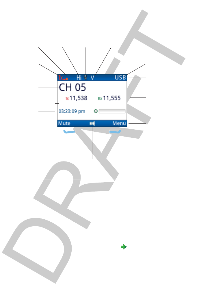
The channel screen
The channel screen shows the following information:
• the name of the currently selected channel
• the transmit and receive frequencies, if applicable
• a bar graph that indicates the signal strength on receive
(green) and the output power on transmit (red)
• the transmit power level setting
• the call type icon (when calling) or the scan indicator (when
scanning)
• the mute type indicator
• the mode
OPERATING THE TRANSCEIVER
THE CHANNEL SCREEN
62 ENVOY™ TRANSCEIVER GETTING STARTED GUIDE
Figure 22: Channel screen
If the transmit and receive frequencies are the same, the frequency
is only shown on the right side of the screen. The Rx/Tx indicator
shows whether the transceiver is receiving (green) or transmitting
(red). The more bars that are shown, the higher the signal strength.
Your transceiver may have the option of selecting high, medium,
or low power. Hi,Med, or Lo is shown respectively to the right of
the signal strength indicator.
While a call is being established, the transceiver shows that calling
activity is in progress by flashing in place of the scan indicator.
Once a call is established, these indicators are replaced with an icon
that represents the type of call being sent or received.
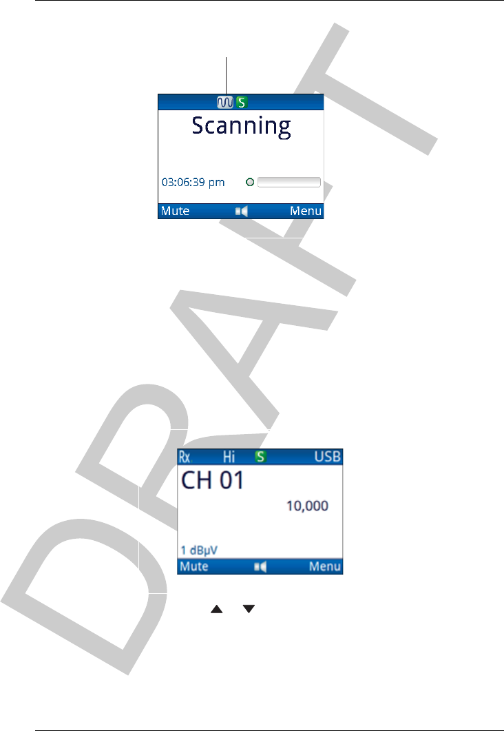
When the transceiver is scanning, the channel screen is replaced by
the scanning screen.
channel name
Tx/Rx frequency
status areas
menu bar
title bar
mode
mute type
indicator
(highlighted
when mute is on)
call type
icon
Tx power
setting
signal
strength
indicator
Rx/Tx
indicator
left
software
key
right
software
key
volume
indicator
OPERATING THE TRANSCEIVER
THE CHANNEL SCREEN
ENVOY™ TRANSCEIVER GETTING STARTED GUIDE 63
Figure 23: Scanning screen
Selecting a channel
To select a channel:
Press PTT to exit to the channel or scanning screen.
If the transceiver is scanning, press SCAN to switch off
scanning.
Press or to scroll to the channel that you want to use.
The channel is selected.
NOTE: If you want to change the sideband, press
MODE. If the mode does not change, there is
only one mode for the channel.
scan indicator

OPERATING THE TRANSCEIVER
THE CHANNEL SCREEN
64 ENVOY™ TRANSCEIVER GETTING STARTED GUIDE
NOTE: If you have an automatic antenna tuner fitted,
press PTT to tune the antenna to the currently
selected channel.
Do any of the following:
•Hold OK to edit the channel, if permitted.
• Press OK to search for a channel.
• Press CALL to start a call.
•Hold CALL to go to Contacts.

OPERATING THE TRANSCEIVER
SCANNING CHANNELS
ENVOY™ TRANSCEIVER GETTING STARTED GUIDE 65
Scanning channels
If you intend to receive calls on several channels, switch on
scanning. When scanning is switched on, the transceiver
sequentially selects each channel/mode in your scan tables to detect
incoming calls. The channel are scanned in a continuous cycle.
Mute is switched on automatically.
NOTE: Only those scan tables that are set to be scanned have
the channels scanned.
When the transceiver detects a call addressed to your station, it
stops scanning and notifies you according to the type of call
received. When you press SCAN to end the call, scanning resumes.
If you do not press this key to end the call, or any other key within
a pre-determined timeout, the transceiver automatically ends the
call and resumes scanning.
NOTE: The default standby state for the transceiver is to
return to scanning so that it is ready to receive calls
across a range of frequencies.
When the transceiver detects voice, it notifies you according to the
mute setting selected. If your transceiver is set to notify you when
voice is detected (V), you can pause scanning, select the
channel/mode on which the voice was heard, then resume scanning
when required. If your transceiver is set to Selcall mute (S), it only
pauses scanning when it detects a call addressed to your station.
It is recommended that scanning is switched on when you are not
using the transceiver to communicate.
Switching scanning on or off
To switch scanning on or off:
Press SCAN.
If a call is not in progress, scanning is toggled on or off.
If a call is in progress, the call is ended and the transceiver
begins scanning.

OPERATING THE TRANSCEIVER
SCANNING CHANNELS
66 ENVOY™ TRANSCEIVER GETTING STARTED GUIDE
NOTE: When scanning is switched on, mute is also
switched on.
NOTE: If you press PTT while the transceiver is
scanning, the scan is stopped.
Pausing scanning
To pause scanning:
Do one of the following:
• To pause scanning on the last-selected channel,
press OK.
• To pause scanning and scroll to another channel,
press or .
The channel/modes through which you can scroll are those
in the scan tables that are being scanned. They are not listed
alphabetically but in the order in which they are being
scanned.
If you do not press a key within 30 sec, the transceiver
automatically resumes scanning.
While scanning is paused, do one of the following:
• To speak on the selected channel, hold down PTT.
• To resume scanning immediately, press OK.

OPERATING THE TRANSCEIVER
MUTING THE TRANSCEIVER
ENVOY™ TRANSCEIVER GETTING STARTED GUIDE 67
Muting the transceiver
When the transceiver is set to a channel or is scanning channels,
and mute is switched off, you hear on-air signals on each channel.
If you do not want to listen to this, you can silence the transceiver
by switching mute on.
You can set the mute to open when a voice signal is detected (Voice
mute V), or only when a call addressed to your station is received
(Selcall mute S). If you have a digital voice encryptor fitted and
active, you can also set the mute to open only when a digitally
encrypted voice signal is detected (Digital Voice mute D).
Switching mute on or off
To switch mute on or off:
Press (Mute) on the channel, scanning or free-tune
screen.
On the 2221, press (Options), scroll to Mute
On|Off, then press (Select).
The V or S in the title bar of the channel screen is
highlighted when mute is on.
Selecting the mute type
To select the mute type:
Press V/S to toggle the mute type between Selcall mute (S)
and Voice mute (V).
NOTE: If you have the AES-256 digital voice
encryptor fitted and active, an additional
mute type of Digital Voice mute (D) is
available.

OPERATING THE TRANSCEIVER
USING THE MICROPHONE
68 ENVOY™ TRANSCEIVER GETTING STARTED GUIDE
Using the microphone
The microphone is located at the top centre of your handset. When
you talk into the microphone:
• hold the microphone side-on and close to your mouth
•hold down PTT
• speak clearly at your normal volume and rate
• release PTT to return to receiving mode
NOTE: By default, the transceiver is set up to transmit a
short beep when you release PTT. This removes the
need for you to say ‘over’ at the end of your
transmission.
CAUTION: Your conversation can be monitored by anyone
tuned to your transmit frequency, unless you are
using one of Codan’s encryption options. Your
signal can potentially travel very large distances.
If PTT is held continuously for a certain length of time, the system
stops transmission, switches to receive and shows an error message
on the control point. This ensures that, even if the PTT button is
being held down accidentally, the battery will not be flattened, and
your transceiver is ready to receive calls.
You can set the length of time the system waits before it cuts
transmission (default is 10 min), or switch this feature off.
OPERATING THE TRANSCEIVER
SETTING THE BASICS
ENVOY™ TRANSCEIVER GETTING STARTED GUIDE 69
Setting the basics
Setting the date and time
The transceiver is set to UTC time in the factory. You set the local
time and time zone offset for the location of the control point. This
feature is useful if you have a communication network that spreads
over several time zones, or you need to time stamp your
transmissions according to the current time at longitude zero.
To set the time and date:
From the main menu, select (General), then (Time
and Date).
Press (Set).
Press to move to the Time Zone entry.
Press or to select the time zone that you want to use.
Press to move to the Daylight Saving entry.
Press or to select the time that you want to use.
Press to move to the Local Time entry.
Press to enter edit mode for the local time.
Press or to scroll to the value that you want to set, then
press to move to the next item.
Repeat this for minutes, seconds and AM/PM values.
Press (Save) to save the local time.
Press to move to the Local Date entry.
Press to enter edit mode for the local date.
Press or to scroll to the value that you want to set, then
press to move to the next item.
Repeat this for the day/month and year, as required.
Press (Save) to save the local date.
Press to move to the Clock entry.
Press or to select the type of clock that you want to use.
OPERATING THE TRANSCEIVER
SETTING THE BASICS
70 ENVOY™ TRANSCEIVER GETTING STARTED GUIDE
Press to move to the Time Format entry.
Press or to select the format that you want to use.
Press to move to the Date Format entry.
Press or to select the format that you want to use.
If you want to review the information that you have entered,
press or to move through the entries.
Press (Save) to save the information.
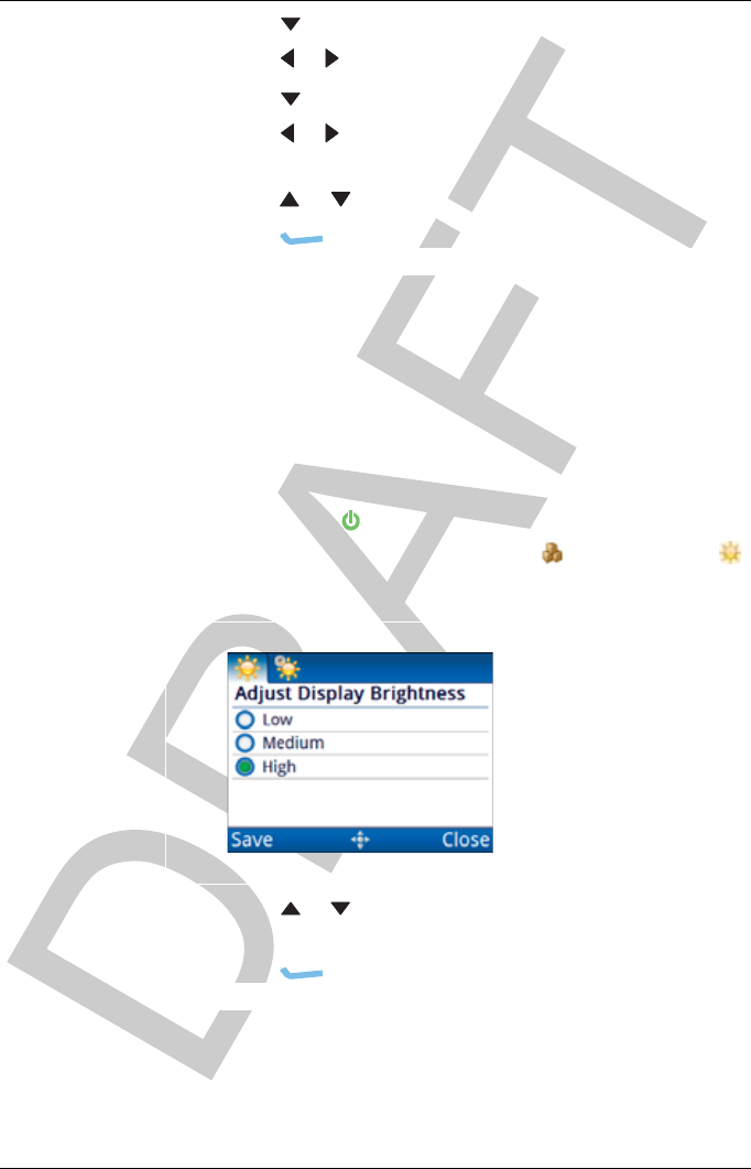
Setting the brightness of the display
To set the brightness:
Do one of the following:
• Press + 0.
• From the main menu, select (General), then
(Brightness).
Press or to scroll to the value that you want to set, then
press OK.
Press (Save) to save the information.
OPERATING THE TRANSCEIVER
CALLING
ENVOY™ TRANSCEIVER GETTING STARTED GUIDE 71
Calling
This section describes how to make the various types of calls from
the transceiver.
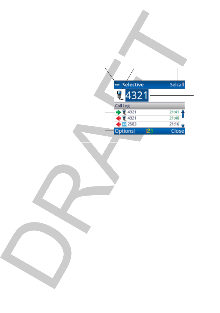
Figure 24: Call screen
NOTE: Additional call types are discussed in the Reference
Manual.
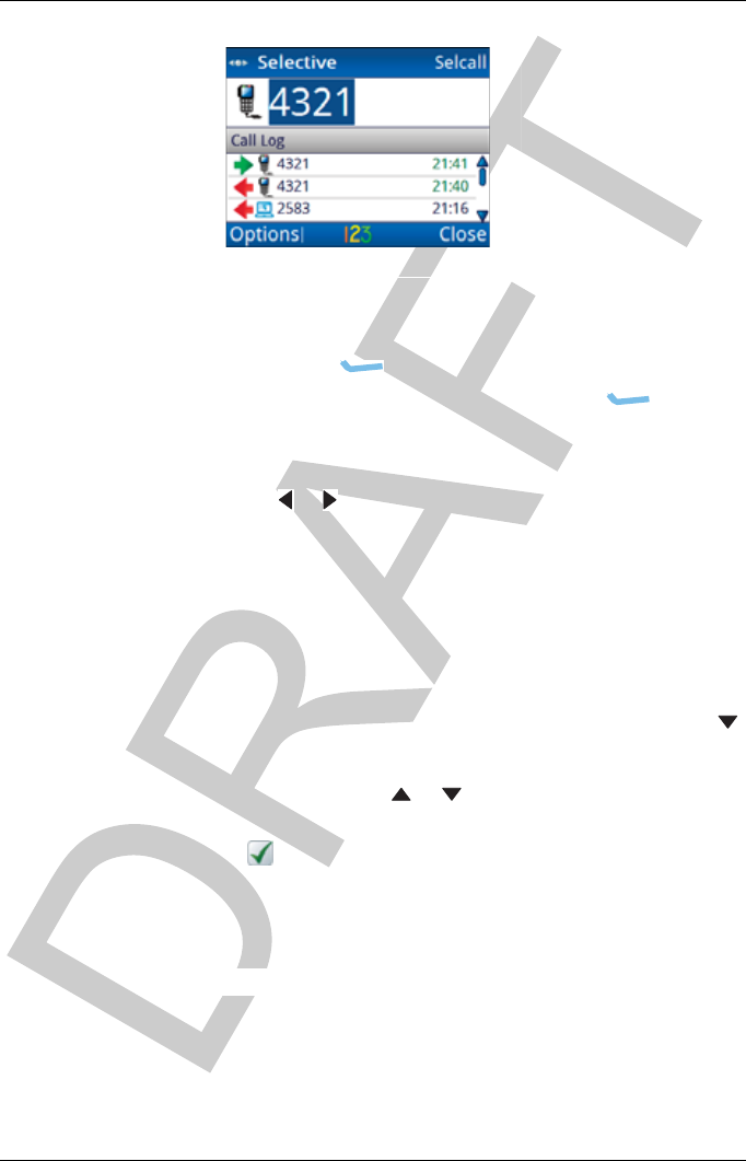
Making a Selective call
If you want to speak with the operator at a particular station, make
a Selective call to the address of that station. When the station
receives the call, the transceiver sounds an alert tone to notify the
operator.
To make a selective call:
Press CALL.
The call type and address of the last call are shown at the top
of the call screen.
incoming call
outgoing call
navigation
indicator
call type HF network
address
select HF network
OPERATING THE TRANSCEIVER
CALLING
72 ENVOY™ TRANSCEIVER GETTING STARTED GUIDE
If you do not want to use the HF network shown at the top
right of the screen:
• Press (Options).
• Scroll to HF Networks, then press (Select).
• Scroll to the HF network that you want to use, then
press OK.
Press or to select the Selective call type if it is not
selected.
Do one of the following:
• To repeat the call to the last address used,
press CALL.
• To call a different station, enter the address, then
press CALL.
• To repeat or return a call from the call log, press
to scroll to the call, then press CALL.
If prompted, press or to scroll to the channel that you
want to use, then press CALL.
A is shown next to the currently selected channel/mode.
To abort the call before it is answered, press PTT or SCAN.
There will be audible beeps or a pop-up message to indicate
that the call has been successful.
OPERATING THE TRANSCEIVER
CALLING
ENVOY™ TRANSCEIVER GETTING STARTED GUIDE 73
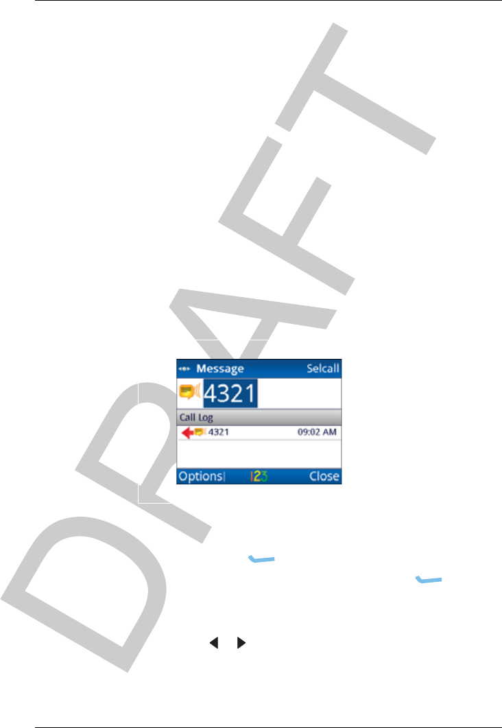
Making a Message call
If you want to send a text message to another station, make a
Message call.
You can:
• enter a message at the time that you make a call
• store up to 10 messages in User Data >Messages for
later use
• store messages in a contact as part of a pre-programmed
Message call
To make a Message call:
Press CALL.
The call type and address of the last call are shown at the top
of the call screen.
If you do not want to use the HF network shown at the top
right of the screen:
•Press (Options).
• Scroll to HF Networks, then press (Select).
• Scroll to the HF network that you want to use, then
press OK.
Press or to select the Message call type if it is not
selected.
OPERATING THE TRANSCEIVER
CALLING
74 ENVOY™ TRANSCEIVER GETTING STARTED GUIDE
Do one of the following:
• To repeat the call to the last address used,
press CALL.
• To call a different station, enter the address, then
press CALL.
• To repeat or return a call from the call log, press
to scroll to the call, then press CALL.
OPERATING THE TRANSCEIVER
CALLING
ENVOY™ TRANSCEIVER GETTING STARTED GUIDE 75
If you want to enter a message:
• Start typing the message.
NOTE: Press OK to start a new line, if
required.
•Press (Options), scroll to OK, then
press (Select) to add the message to the call.
If you want to select a message from a list of stored
messages:
•Press (Options), scroll to Stored, then
press (Select).
• Press or to scroll to the message that you want
to use.
NOTE: If you want to view the message,
press (Details) to view the
message, then press (Close).
•PressOK to select the message.
• Edit the message, if required.
OPERATING THE TRANSCEIVER
CALLING
76 ENVOY™ TRANSCEIVER GETTING STARTED GUIDE
• Press (Options), scroll to OK, then
press (Select).
If prompted, press or to scroll to the channel that you
want to use, then press CALL.
A is shown next to the currently selected channel/mode.
To abort the call before it is answered, press PTT or SCAN.
There will be audible beeps or a pop-up message to indicate
that the call has been successful.
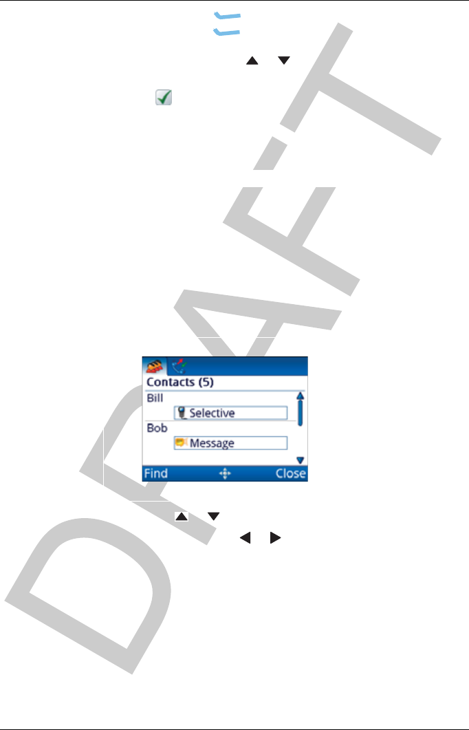
Making a call to a contact
To make a call to a contact:
Hold CALL.
Press or to scroll to the contact who you want to call.
If required, press or to scroll to the call that you want
to make.
The call types that are available for the contact are set up in
User Data >Contacts.
NOTE: If only one call has been set up for the
contact, you cannot select a different call type
at the time of the call.
Press CALL.
OPERATING THE TRANSCEIVER
CALLING
ENVOY™ TRANSCEIVER GETTING STARTED GUIDE 77
If prompted, press or to scroll to the channel that you
want to use, then press CALL.
A is shown next to the currently selected channel/mode.
To abort the call before it is answered, press PTT or SCAN.
There will be audible beeps or a pop-up message to indicate
that the call has been successful.
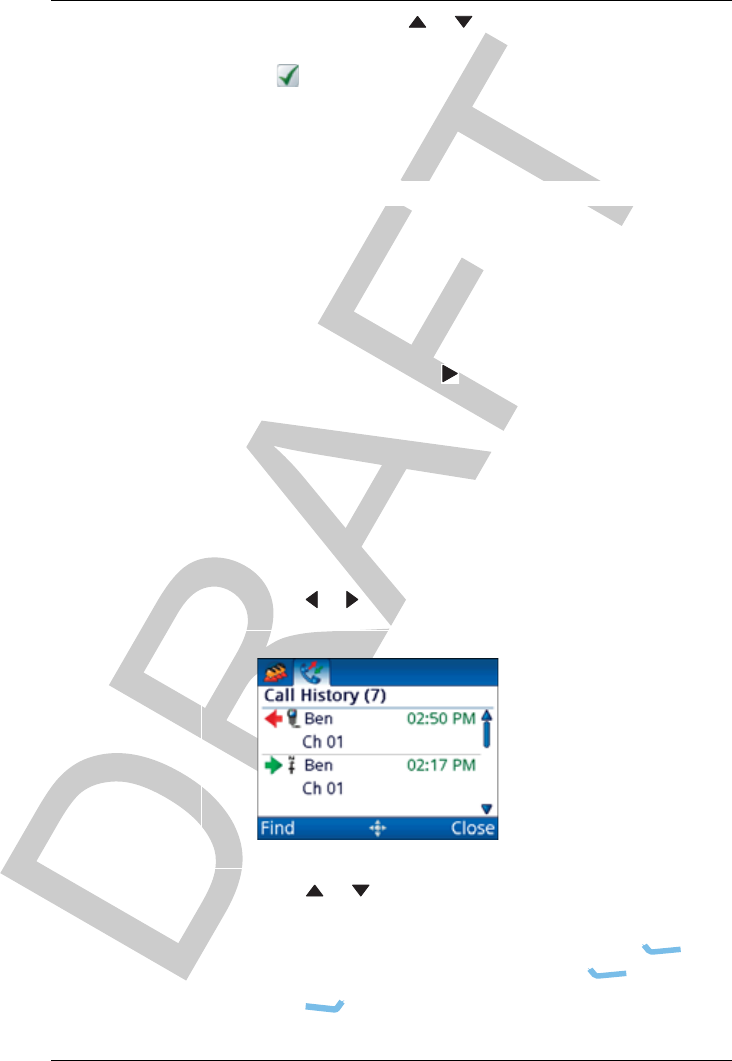
Making a call from the Call History
The Envoy™ Transceiver stores information on the calls that you
send and receive. The detailed call history is accessed by
holding CALL, then pressing to scroll to the Call History tab.
NOTE: A filtered call log is available in the call screen. This
log contains only the latest instance of a call to a
specific station.
To make a call from the Call History:
Hold CALL.
Press or to select the Call History tab.
Press or to scroll to the call that you want to return or
repeat, then press CALL.
If you want to view the details of the call, press
(Options), scroll to Details, then press (Select).
Press (Close) to exit viewing the details.
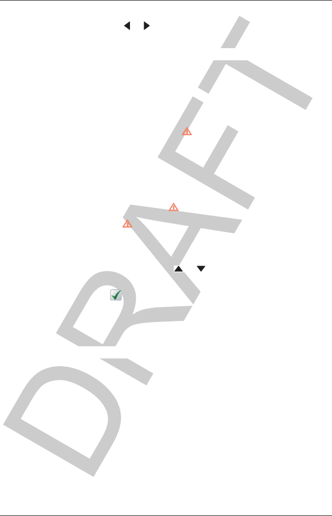
OPERATING THE TRANSCEIVER
CALLING
78 ENVOY™ TRANSCEIVER GETTING STARTED GUIDE
Press CALL.
Press or to select the call type that you want to use.
Continue from making your chosen call type.
Making a call from the Emergency key
You can set up emergency contacts with calls that are chained
together when you hold the key.
CAUTION: If you have more than one emergency contact, you
will be prompted to select the emergency contact that
you want to call at the time of the call.
NOTE: For more information, see the Reference Manual.
To make a call from the key:
Hold for 2 sec.
If you have more than one emergency contact, scroll to the
contact that you want to call, then press CALL.
If prompted, press or to scroll to the channel that you
want to use, then press CALL.
A is shown next to the currently selected channel/mode.
To abort the call before it is answered, press PTT or SCAN.
There will be audible beeps or a pop-up message to indicate
that the call has been successful.
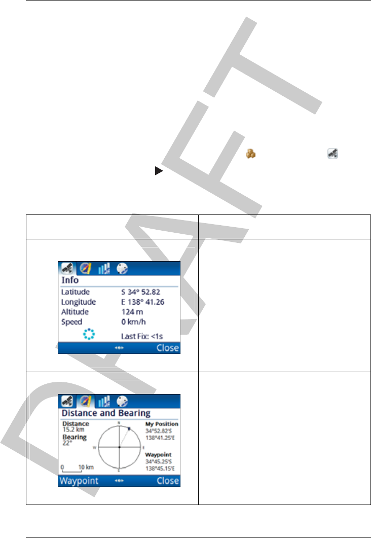
OPERATING THE TRANSCEIVER
USING GPS
ENVOY™ TRANSCEIVER GETTING STARTED GUIDE 79
Using GPS
Viewing GPS information
NOTE: You can view GPS information if the GPS Call
option is installed.
To view GPS information:
From the main menu, select (General), then (GPS).
Press to move to the tab that you want to view.
Table 3: GPS information
Tab Description
Latitude and longitude readings from a
GPS receiver, or from Settings >
GPS >My Position. Altitude and
speed readings are hidden by default.
The spinning circle shows that the GPS
receiver is active, and the Last Fix
reading shows the time lapse from the
last receipt of valid GPS information.
Distance and bearing from your
location to a selected waypoint.
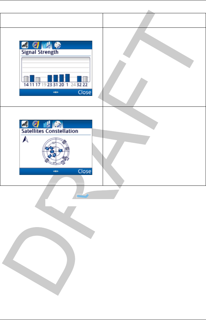
OPERATING THE TRANSCEIVER
USING GPS
80 ENVOY™ TRANSCEIVER GETTING STARTED GUIDE
Press (Close).
Signal strength from each visible
satellite. The number represents a
particular satellite, and its location is
shown on the Satellites Constellation
tab. Satellites with a blue signal
strength provide information for the
GPS location.
Map of visible satellites. The satellites
that are coloured blue are providing the
strongest signals and this information is
being used to establish the position of
the receiver. The other satellites are
visible, but the signal is weaker and
information is ignored.
Table 3: GPS information (cont.)
Tab Description
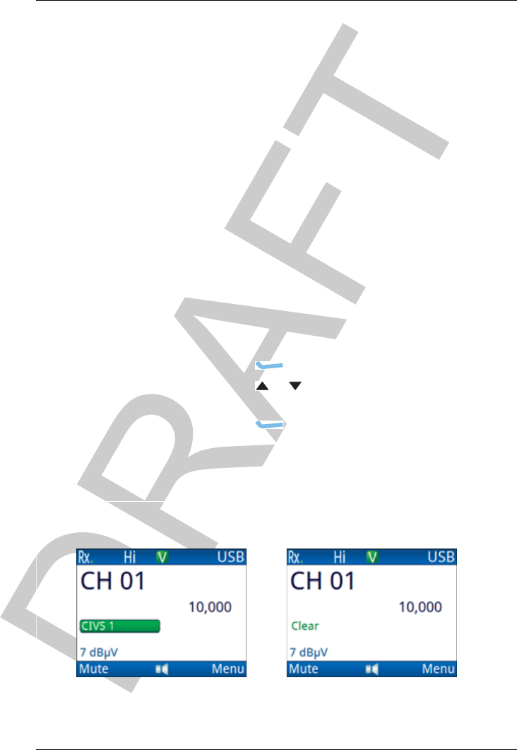
OPERATING THE TRANSCEIVER
USING ENCRYPTION
ENVOY™ TRANSCEIVER GETTING STARTED GUIDE 81
Using encryption
Switching the encryptor on or off
The 2220 Handset and 2230 Desk Console have hot keys that
access the secure feature directly. With the 2221 Handset, you
access the secure feature via Functions.
If you want secure to remain on at all times, you set this in
Settings >Security > Secure Start State.
NOTE: For more information, see the Reference Manual.
To switch the encryptor on or off:
If you are using a 2220 Handset or 2230 Desk Console,
press SEC.
If you are using a 2221 Handset:
•Press (Options).
• Press or to scroll to the Secure On|Secure
Off option.
•Press (Select).
Secure is toggled on or off across all available encryptors.
For CIVS voice scrambling you will see:
Secure Clear
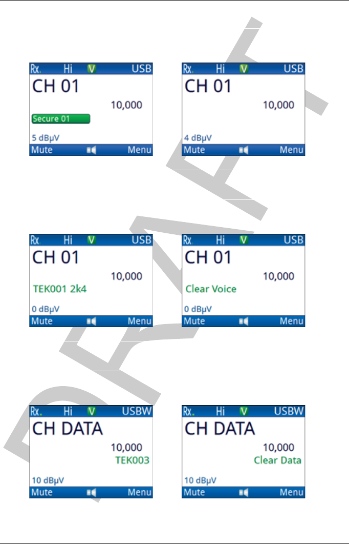
OPERATING THE TRANSCEIVER
USING ENCRYPTION
82 ENVOY™ TRANSCEIVER GETTING STARTED GUIDE
For CES-128 voice encryption you will see:
For AES-256 digital voice encryption you will see:
For AES-256 digital data encryption you will see:
Secure Clear
Secure Clear
Secure Clear
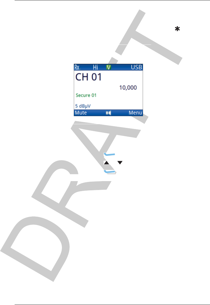
OPERATING THE TRANSCEIVER
USING ENCRYPTION
ENVOY™ TRANSCEIVER GETTING STARTED GUIDE 83
Change to the encryptor type that you want to use, if
permitted.
If you are using CES-128 voice encryption with a
2220 Handset or 2230 Desk Console, press to go to
secure standby mode, if enabled and required.
If you are using CES-128 voice encryption with a
2221 Handset, do the following to go to secure standby
mode:
•Press (Options).
• Press or to scroll to the Standby On option.
•Press (Select).
Standby
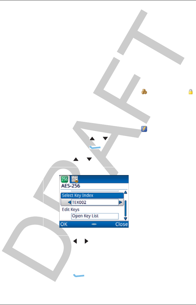
OPERATING THE TRANSCEIVER
USING ENCRYPTION
84 ENVOY™ TRANSCEIVER GETTING STARTED GUIDE
Selecting a secure key
If an encryptor contains two or more keys, you have the option of
selecting a different key for encryption, if permitted. When
AES-256 digital voice and data encryptors are used together, the
selected key is common to both.
To select a secure key:
If you are using a 2220 Handset or 2230 Desk Console, do
one of the following:
• From the main menu, select (General), then
(Secure).
•Hold SEC.
If you are using a 2221 Handset:
• From the main menu, select (Functions).
• Press or to scroll to the Secure Info function.
• Press (OK).
Press or to scroll to the Select Key Index entry.
Press or to select the secure key index that you want to
use.
Hold the key to scroll rapidly through the secure key
indexes.
Press (OK).
The transceiver goes secure on the selected key.
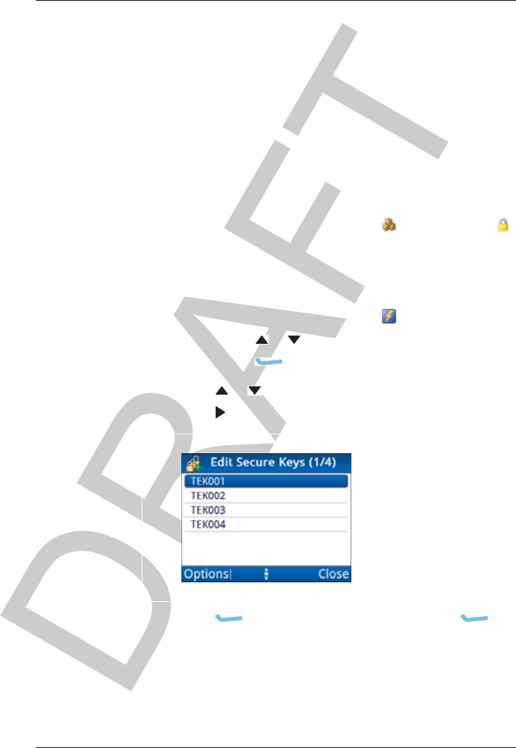
OPERATING THE TRANSCEIVER
USING ENCRYPTION
ENVOY™ TRANSCEIVER GETTING STARTED GUIDE 85
Adding a secure key
If you are permitted to add a secure key for a CES-128 or AES-256
encryptor, the transceiver automatically selects the next empty
secure index into which you can enter a secure key. You cannot
select the secure key index.
To add a secure key:
If you are using a 2220 Handset or 2230 Desk Console, do
one of the following:
• From the main menu, select (General), then
(Secure).
•Hold SEC.
If you are using a 2221 Handset:
• From the main menu, select (Functions).
• Press or to scroll to the Secure Info function.
•Press (OK).
Press or to scroll to the Edit Keys entry.
Press .
Press (Options), scroll to Add, then press
(Select).
NOTE: If all secure key indexes contain a key, Add
is not shown as an option.
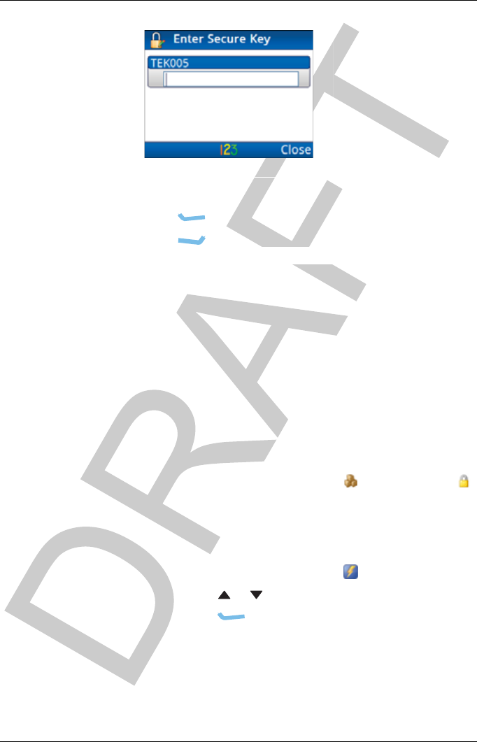
OPERATING THE TRANSCEIVER
USING ENCRYPTION
86 ENVOY™ TRANSCEIVER GETTING STARTED GUIDE
Enter the characters that you want to use for the secure key.
Press (Save) to save the information.
Press (Close).
Selecting the data rate
The data rate affects the speed with which digitally encrypted
transmissions are sent.
To select a different data rate:
If you are using a 2220 Handset or 2230 Desk Console, do
one of the following:
• From the main menu, select (General), then
(Secure).
•Hold SEC.
If you are using a 2221 Handset:
• From the main menu, select (Functions).
• Press or to scroll to the Secure Info function.
• Press (OK).

OPERATING THE TRANSCEIVER
USING ENCRYPTION
ENVOY™ TRANSCEIVER GETTING STARTED GUIDE 87
Press or to select the data rate that you want to use.
Press (OK).

OPERATING THE TRANSCEIVER
USING A CROSSPATCH
88 ENVOY™ TRANSCEIVER GETTING STARTED GUIDE
Using a crosspatch
Overview of the 3031 Crosspatch
The 3031 Crosspatch is a device that connects an HF
communication system with a VHF or UHF communication
system.
NOTE: For details on installing the crosspatch and its
operation, see the documentation provided with the
device.
NOTE: You must select the 3031 Crosspatch as the
peripheral device for the 15-way connector.
The operating mode of the crosspatch may be controlled directly by
the transceiver, or by using DTMF commands on a DTMF-capable
VHF/UHF transceiver.
The crosspatch may be active, on standby, or switched off. The
status of the crosspatch is shown in the title bar, and you can set the
status to be shown in one of the status areas.
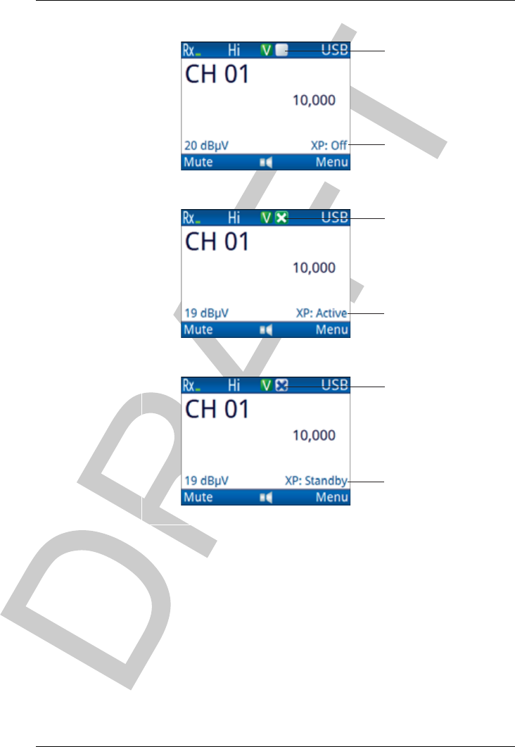
OPERATING THE TRANSCEIVER
USING A CROSSPATCH
ENVOY™ TRANSCEIVER GETTING STARTED GUIDE 89
Figure 25: Crosspatch status
crosspatch indicator
Off
crosspatch indicator
Active
crosspatch indicator
Standby
crosspatch state
crosspatch state
crosspatch state
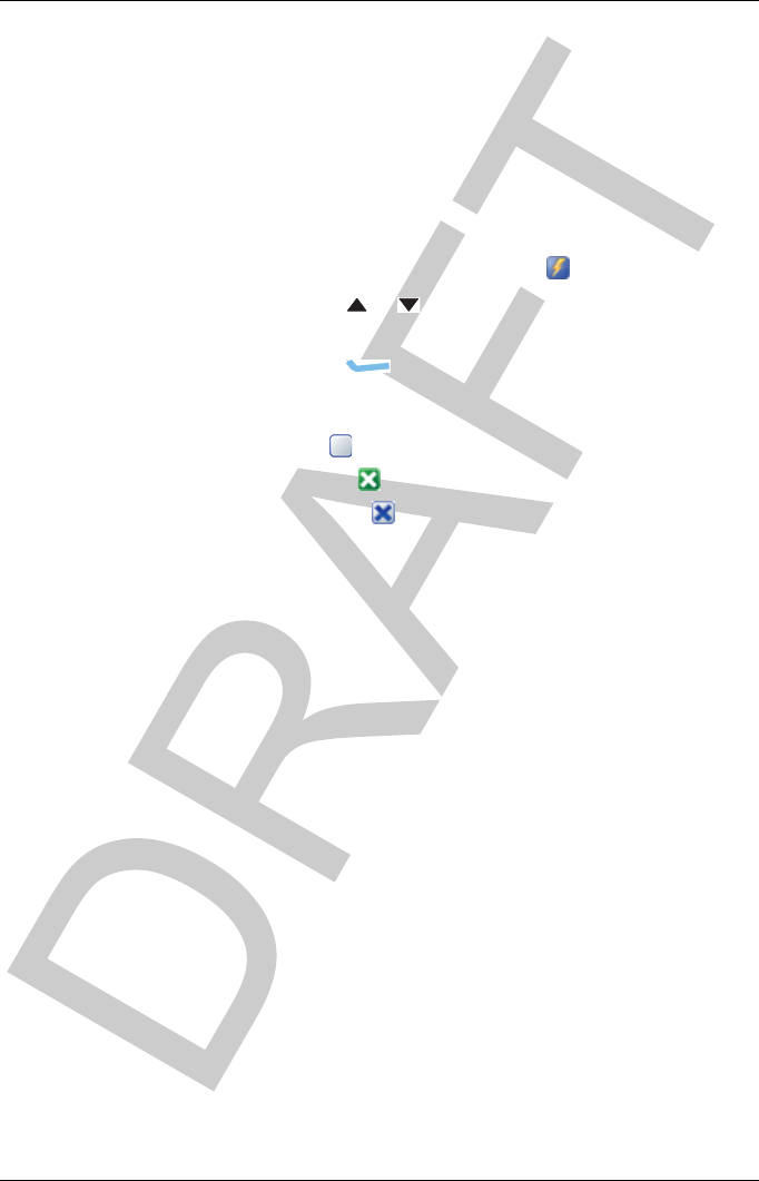
OPERATING THE TRANSCEIVER
USING A CROSSPATCH
90 ENVOY™ TRANSCEIVER GETTING STARTED GUIDE
Changing the operating mode of the crosspatch
To change the operating mode of the crosspatch:
If you are using a 2220 Handset or 2230 Desk Console,
press 5.
If you are using a 2221 Handset:
• From the main menu, select (Functions).
• Press or to scroll to the Next Crosspatch
State function.
• Press (OK).
The crosspatch toggles between the following states:
•Off
•Active
• Standby
NOTE: If the status shows XP: Disconnected, the
crosspatch may not be connected, or is
connected but not selected as a peripheral
device.

OPERATING THE TRANSCEIVER
UPGRADING THE TRANSCEIVER VIA A USB STICK
ENVOY™ TRANSCEIVER GETTING STARTED GUIDE 91
Upgrading the transceiver via a USB
stick
Firmware packages, profiles from TPS, and secure keys may be
loaded onto a USB stick, providing a portable method of upgrading
transceivers in the field. You can also read a profile from a
transceiver in the field. When the USB stick is connected to the
control point, a selection menu is shown for various activities,
depending on the values set in Settings >General >USB User
Access.
To manage profiles, firmware, and secure keys:
Connect your USB stick to the control point using a
standard USB A (female) to micro USB cable.
The USB stick is detected automatically.
Press or to scroll to the activity that you want to
perform from the following:
• If you want to program a profile from the USB stick
to the transceiver, select Program Profile.
• If you want to read the profile from the transceiver to
the USB stick, select Read Profile.
• If you want to upgrade the transceiver with a
firmware package from the USB stick, select
Upgrade Firmware.
• If you want to program secure keys to a transceiver
that has an encryptor module enabled, select
Program Secure Keys.

OPERATING THE TRANSCEIVER
UPGRADING THE TRANSCEIVER VIA A USB STICK
92 ENVOY™ TRANSCEIVER GETTING STARTED GUIDE
Do one of the following:
• Press or to scroll to the firmware package,
profile, or key set file, press (Options), scroll
to Open, then press (Select).
• Press or to scroll to the folder in which you
want to save the profile from the transceiver, then
press (Save).
Press (Yes) to confirm that you want to complete the
selected action.
Perform more tasks with the USB stick as required.
Press (Eject) when you have finished working with
the USB stick.

ENVOY™ TRANSCEIVER GETTING STARTED GUIDE 93
6Contacts
This section contains the following topics:
•Adding a contact on page 94
•Adding a contact from the Call Log, Call History, or Last
Heard Log on page 102
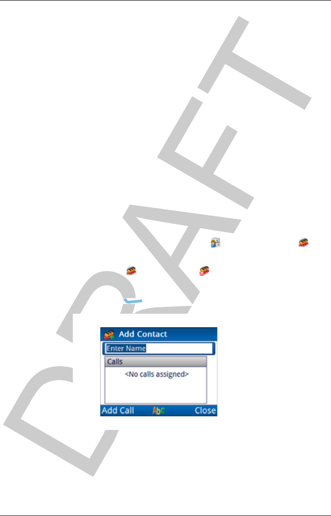
CONTACTS
ADDING A CONTACT
94 ENVOY™ TRANSCEIVER GETTING STARTED GUIDE
Adding a contact
Contacts are used to pre-define the typical calls that you want to
make to another person. For each contact you can define a number
of calls. Each call contains information about:
• the call system that you want to use
• the type of call that you want to make to the contact
• the address or telephone number of the station at which this
contact may be located
NOTE: You can select some of the call information to
prompt you for a choice at the time that a call is made
via the contact. The Prompt value is available in
these instances.
To add a contact:
From the main menu, select (User Data), then
(Contacts).
Select (Contacts) or (Emergency Contacts), as
required.
Press (Add).
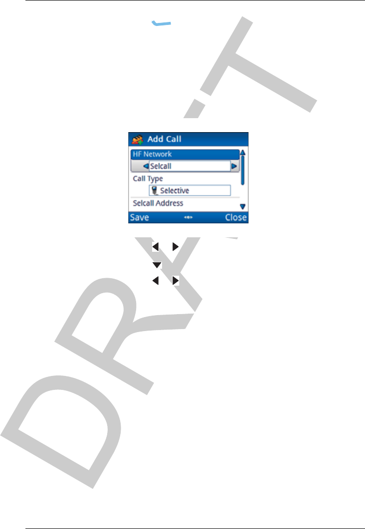
CONTACTS
ADDING A CONTACT
ENVOY™ TRANSCEIVER GETTING STARTED GUIDE 95
Enter the name that you want to use for the contact, then
press (Add Call).
The HF Network entry is highlighted.
The HF network defines the call system and self address that
is used by your station when the call is made. For example,
if you want to select a channel for the call, use a Selcall HF
network. If you want the transceiver to automatically select
a channel for the call, use an ALE/CALM HF network.
Press or to select the HF network that you want to use.
Press to move to the Call Type entry.
Press or to select the call type that you want to use.
NOTE: The call type that you select affects
information that you can enter for the
remainder of this call.
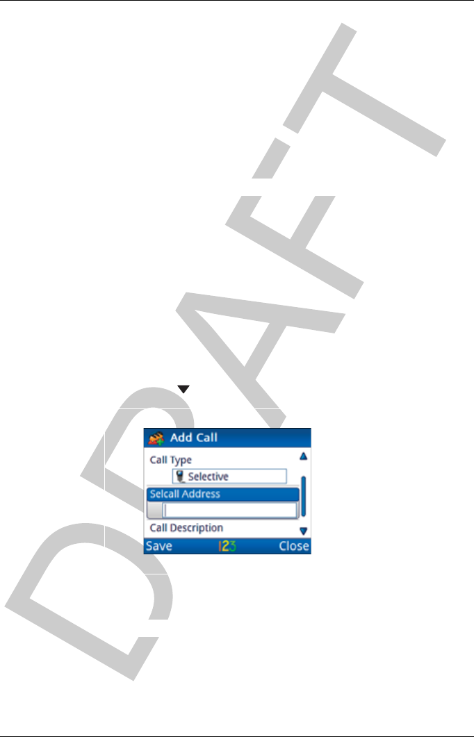
CONTACTS
ADDING A CONTACT
96 ENVOY™ TRANSCEIVER GETTING STARTED GUIDE
If you are adding:
• a Selective, Channel Test, Emergency, Get Position
or Send Position call, continue from Adding a simple
call on page 96
• a Message call Adding a Message call on page 97
• a Phone call Adding a Phone call on page 98
• a Get Status call Adding a Get Status call on page 99
•an RFDS Emergency call Adding an RFDS
Emergency call on page 100
Adding a simple call
A simple call is a call that requires an address only at this stage of
the definition process.
To continue with adding a Selective, Channel Test, Emergency,
Get Position or Send Position call:
Press to move to the Selcall|ALE Address entry.
Enter the address of the station that you want to call.
Continue from Completing the contact on page 101.
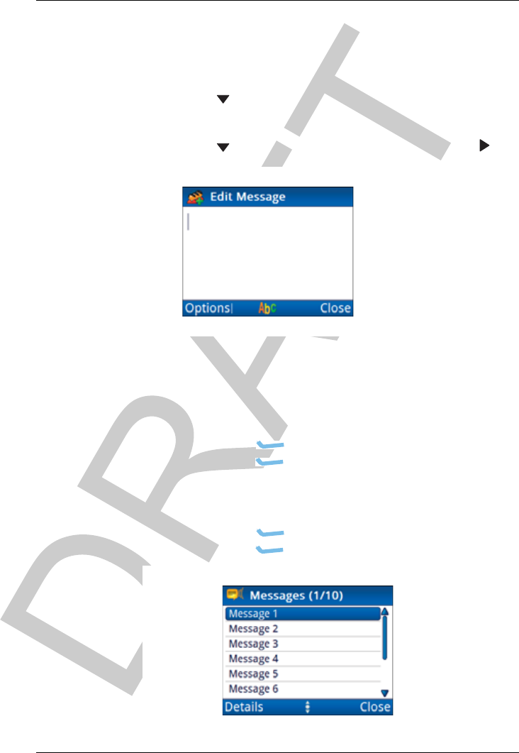
CONTACTS
ADDING A CONTACT
ENVOY™ TRANSCEIVER GETTING STARTED GUIDE 97
Adding a Message call
To continue with adding a Message call:
Press to move to the Selcall|ALE Address entry.
Enter the address of the station that you want to call.
Press to move to the Message entry, then press .
If you want to enter a message:
• Start typing the message.
NOTE: Press OK to start a new line, if
required.
•Press (Options), scroll to OK, then
press (Select) to add the message to the call.
If you want to select a message from a list of stored
messages:
•Press (Options), scroll to Stored, then
press (Select).
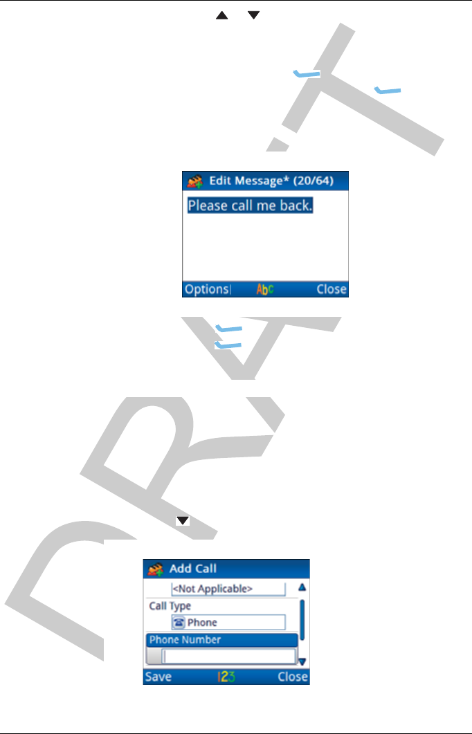
CONTACTS
ADDING A CONTACT
98 ENVOY™ TRANSCEIVER GETTING STARTED GUIDE
• Press or to scroll to the message that you want
to use.
NOTE: If you want to view the message,
press (Details) to view the
message, then press (Close).
• Press OK to select the message.
• Edit the message, if required.
• Press (Options), scroll to OK, then
press (Select).
Continue from Completing the contact on page 101.
Adding a Phone call
To continue with adding a Phone call:
Press to move to the Phone Number entry.
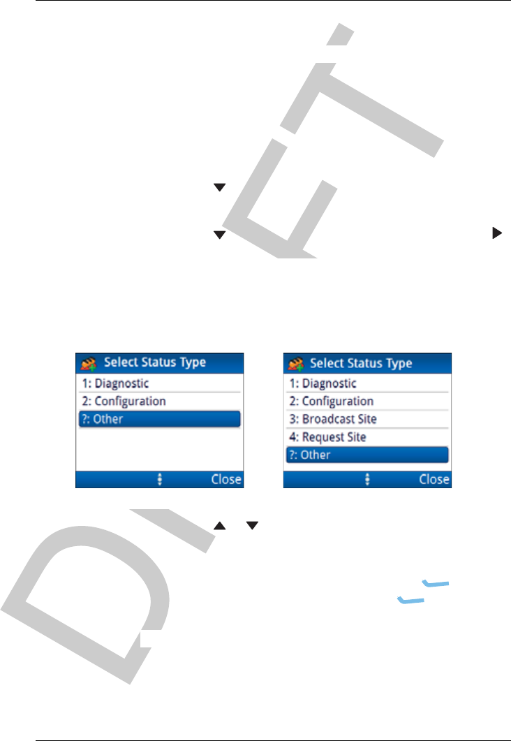
CONTACTS
ADDING A CONTACT
ENVOY™ TRANSCEIVER GETTING STARTED GUIDE 99
Enter the phone number.
Continue from Completing the contact on page 101.
Adding a Get Status call
To continue with adding a Get Status call:
Press to move to the Selcall|ALE Address entry.
Enter the address of the station that you want to call.
Press to move to the Status Type entry, then press .
Press or to scroll to the status type that you want to
use, then press OK.
If you selected ?: Other as the status type, enter the
text/command that you want to send, press
(Options), scroll to Save, then press (Select).
Continue from Completing the contact on page 101.
Selcall HF network ALE/CALM HF network
ALE Site Manager:
Auto
Manual
Restricted

CONTACTS
ADDING A CONTACT
100 ENVOY™ TRANSCEIVER GETTING STARTED GUIDE
Adding an RFDS Emergency call
NOTE: RFDS Emergency calls are only available when an
RFDS HF network is selected or you set the HF
Network entry to Prompt.
To continue with adding an RFDS Emergency call:
Continue from Completing the contact on page 101.
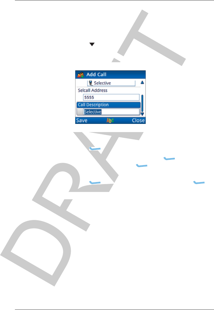
CONTACTS
ADDING A CONTACT
ENVOY™ TRANSCEIVER GETTING STARTED GUIDE 101
Completing the contact
To finish entering the information required for the contact:
Press to move to the Call Description entry.
By default, the call type is entered as the call description.
Enter the description that you want to use for this call.
Press (Save) to save the information.
If you want to add another call, press (Options),
scroll to Add Call, press (Select), then repeat the
steps for adding a call.
Press (Options), scroll to Save, then press
(Select).
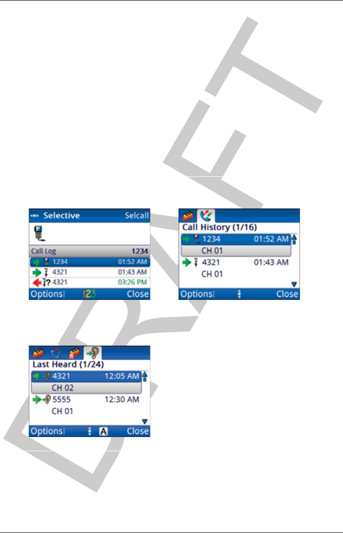
CONTACTS
ADDING A CONTACT FROM THE CALL LOG, CALL HISTORY,OR LAST HEARD LOG
102 ENVOY™ TRANSCEIVER GETTING STARTED GUIDE
Adding a contact from the Call Log, Call
History, or Last Heard Log
You can save information from the Call Log, Call History, or Last
Heard Log to Contacts. This can either be a new call type for an
existing contact, or you can add a new contact to hold this call
information. The Call Log and Call History are separate entities,
however, the process for saving the call information to a contact is
the same.
Figure 26: Call Log, Call History and Last Heard Log
Call Log Call History
Last Heard Log

CONTACTS
ADDING A CONTACT FROM THE CALL LOG, CALL HISTORY,OR LAST HEARD LOG
ENVOY™ TRANSCEIVER GETTING STARTED GUIDE 103
To add a contact from the Call Log, Call History, or Last Heard
Log:
Do one of the following:
•PressCALL, then press or to scroll to the
entry in the Call Log.
•Hold CALL, press , then press or to scroll to
the entry in the Call History.
Press (Options), scroll to Save, then press
(Select).
You are informed if there is a matching contact for the
address in the call, and whether or not you want to append
this call to that contact. If there is no matching contact you
can create a new contact.
Do one of the following:
• If there is a matching contact who you want to use,
press (Yes), then edit the call as required.
• If you do not want to use the matching contact,
press (No), create a new contact, then edit the
call as required.
• If there is no matching contact, edit the call as
required.
Press (Save) to save the information.
If the contact does not exist, enter a name for the contact,
then press (Save).

CONTACTS
ADDING A CONTACT FROM THE CALL LOG, CALL HISTORY,OR LAST HEARD LOG
104 ENVOY™ TRANSCEIVER GETTING STARTED GUIDE
This page has been left blank intentionally.

ENVOY™ TRANSCEIVER GETTING STARTED GUIDE 105
7Specifications
Table 4: Specifications
Item Specification
Frequency range Transmit: 1.6 to 30 MHz
Receive: 0.25 to 30 MHz
Channel capacity
(single or two-frequency
simplex channels)
X1: 100 (International)
400 (Australia)
X2: 1000
Operating modes Single sideband (J3E) USB and LSB or switched
USB/LSB, AM (A3E Rx, H3E Tx), CW (J1A, A1A)
Environment Ambient temperature: í30 to +60°C
(–22 to 140°F)
Relative humidity: 95%
Derate upper ambient temperature by 1°C (33.8°F) per
330 m (360 yd) above sea level
Cooling Convection or fan (Option F)

SPECIFICATIONS
106 ENVOY™ TRANSCEIVER GETTING STARTED GUIDE
Size 2210 RFU: 210 mm W × 270 mm D × 65 mm H
(8.4inW × 10.8inD × 2.6inH)
2220/2221
Handset:
74 mm W × 32 mm D × 150 mm H
(2.9inW × 1.3inD × 5.9inH)
2230 Desk
Console:
190 mm W × 233 mm D × 81 mm H
(7.5inW × 9.2inD × 3.2inH)
Handset and
speaker
connector:
42 mm W × 55 mm D × 22 mm H
(1.7inW × 2.2inD × 0.9inH)
Weight 2210 RFU: 2.8 kg
(6.2 lb)
2220/2221
Handset:
0.3 kg
(0.7 lb)
2230 Desk
Console:
1kg
(2.2 lb)
Handset and
speaker
connector:
0.4 kg
(0.9 lb)
Sealing All units: IP41
Table 4: Specifications (cont.)
Item Specification

ENVOY™ TRANSCEIVER GETTING STARTED GUIDE 107
AInstalling the
transceiver
This section contains the following topics:
•Overview of mobile stations on page 108
•Overview of fixed stations on page 114

INSTALLING THE TRANSCEIVER
OVERVIEW OF MOBILE STATIONS
108 ENVOY™ TRANSCEIVER GETTING STARTED GUIDE
Overview of mobile stations
A mobile station typically consists of a transceiver, a 12 V DC
power supply (battery), an antenna, control and accessory devices,
ancillary equipment, and appropriate connecting cables. The
antenna is connected to the transceiver by coaxial cable. An
automatic tuning antenna also requires a control cable connected to
the transceiver.
When space is limited in a mobile situation, the transceiver may be
located in the boot or behind/under a seat.
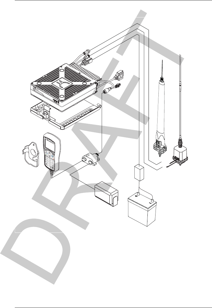
INSTALLING THE TRANSCEIVER
OVERVIEW OF MOBILE STATIONS
ENVOY™ TRANSCEIVER GETTING STARTED GUIDE 109
Figure 27: Typical mobile station
NOTE: A range of ancillary equipment may be connected to
the Envoy™ Transceiver using the 6-way and
15-way connectors at the rear of the RFU.
CALL SCAN
OK
1
TUNEFUNCMODE
FREE Rx
SEC
VS
VIEW
EASI
TALK
ABCDEF
GHIJKL MNO
PQRSTUVWXYZ
23
456
789
0
RF Unit
™
Type 2210
Serial No.
antenna control
antenna
battery
battery
speaker
handset
handset cradle
RFU
RFU cradle
handset and speaker
connector
10-way
connector
15-way
connector
6-way
connector
9350
3040
fuse
08-06022-001
08-03255
08-01503-00x
08-05627-00x

INSTALLING THE TRANSCEIVER
OVERVIEW OF MOBILE STATIONS
110 ENVOY™ TRANSCEIVER GETTING STARTED GUIDE
Cables in a mobile station
Mounting a mobile Envoy™ station
Most components of a mobile Envoy™ station are provided with
their own mounting cradles. For general guidance on suitable
locations for equipment and installing these stations see the
reference material on the enclosed CD.
Mounting the handset cradle
To mount the handset cradle:
Mount the handset according to the fitting instructions
(Codan part number 15-00149-001) provided with the
handset cradle.
Table 5: Cables for a typical mobile Envoy™ station
Cable Symbol Part number
Handset and speaker connector108-06022-001
Coaxial cable between RFU and antenna208-01503-006
Control cable between RFU and antennab08-05627-006
DC power supply cablea08-03255
1. The part number for the cable corresponds to a standard 6 m cable.
2. The part number for the cable corresponds to a standard 6 m cable. The cable is also available in a
number of shorter and longer lengths.

INSTALLING THE TRANSCEIVER
OVERVIEW OF MOBILE STATIONS
ENVOY™ TRANSCEIVER GETTING STARTED GUIDE 111
Mounting the speaker
To mount the speaker:
Secure the mounting cradle to the surface with at least two
screws.
Ensure there is sufficient space at the rear for the cable.
Attach the speaker to the cradle with the two screws and
rubber washers.
Mounting the handset and speaker connector
To mount the handset and speaker connector:
Use cable ties or screws to secure the handset and speaker
connector in a suitable location.
Mounting the RFU
CAUTION: If you are transferring a fixed station to a mobile
station and you have installed rubber feet to the
bottom of the RFU, you must remove the rubber feet
before installing it into the mounting cradle.
To mount the RFU:
Secure the mounting cradle to the surface with at least four
screws, one in each corner of the cradle.
NOTE: Ensure there is sufficient space at the rear of
the cradle to clear the RFU heatsink.
If the key is locked to the base of the cradle, flip the key
away from the base until it can be rotated (see Figure 27),
then rotate the key in a counterclockwise direction.
Place the RFU into the cradle and push it under the tabs at
the rear of the cradle, then hold the clamp against the front
of the RFU.
Rotate the key clockwise, then push the key toward the base
of the cradle to lock the RFU into position.

INSTALLING THE TRANSCEIVER
OVERVIEW OF MOBILE STATIONS
112 ENVOY™ TRANSCEIVER GETTING STARTED GUIDE
Connecting a mobile Envoy™ station
NOTE: A typical mobile station is shown in Figure 27.
To connect a mobile station:
Connect the cable (Codan part number 08-06022-001) from
the handset and speaker connector to the 10-way plug on the
cable lead from the RFU, then secure the locking ring
tightly into position.
Connect the plug of the handset cable to the socket on the
handset and speaker connector, then secure the locking ring
tightly into position.
Connect the plug at the end of the speaker cable to the
socket on the handset and speaker connector, then secure the
cable by pushing it into the slot on the side of the connector.
Connect the plug at the end of the cable (Codan part
number 08-01503-00x) to the socket at the end of the cable
lead from the RFU, then secure the locking ring tightly into
position.
Connect the plug at the opposite end of the cable (Codan
part number 08-01503-00x) to the socket located at the base
of the antenna, then secure the locking ring tightly into
position.
Connecting the control cable to an automatic tuning antenna
To connect the control cable to an antenna:
Connect the socket at the end of the cable (Codan part
number 08-05627-00x) into the plug at the base of the
antenna, then secure the locking ring tightly into position.
Fit the plug at the opposite end of the cable (Codan part
number 08-05627-00x) into the socket at the end of the
lead from the RFU.

INSTALLING THE TRANSCEIVER
OVERVIEW OF MOBILE STATIONS
ENVOY™ TRANSCEIVER GETTING STARTED GUIDE 113
Connecting the power supply
To connect the transceiver to the battery power supply:
If you are using a 24 V battery supply, connect the battery
to a 24 V to 12 V voltage regulator (Codan part number
15-00508).
Connect the power supply cable (Codan part number
08-03255) to the plug at the end of the 12 V cable lead from
the RFU.
Route the power supply cable according to the instructions
supplied with the Vehicle Installation Kit (Codan part
number 15-00112).
Insert the 32 A fuse and holder in the power supply cable at
a convenient location, as close as possible to the battery
terminals.
Connect the power supply cable to the battery terminals,
black to negative, red to positive.

INSTALLING THE TRANSCEIVER
OVERVIEW OF FIXED STATIONS
114 ENVOY™ TRANSCEIVER GETTING STARTED GUIDE
Overview of fixed stations
A fixed station typically consists of a transceiver, an AC
transceiver supply connected directly to the mains, an antenna,
control and accessory devices, ancillary equipment, and
appropriate connecting cables. The transceiver is connected to the
DC output lead of the transceiver supply. The antenna is connected
to the transceiver by coaxial cable.
NOTE: A fixed station may also be powered via a battery
system or solar power system.
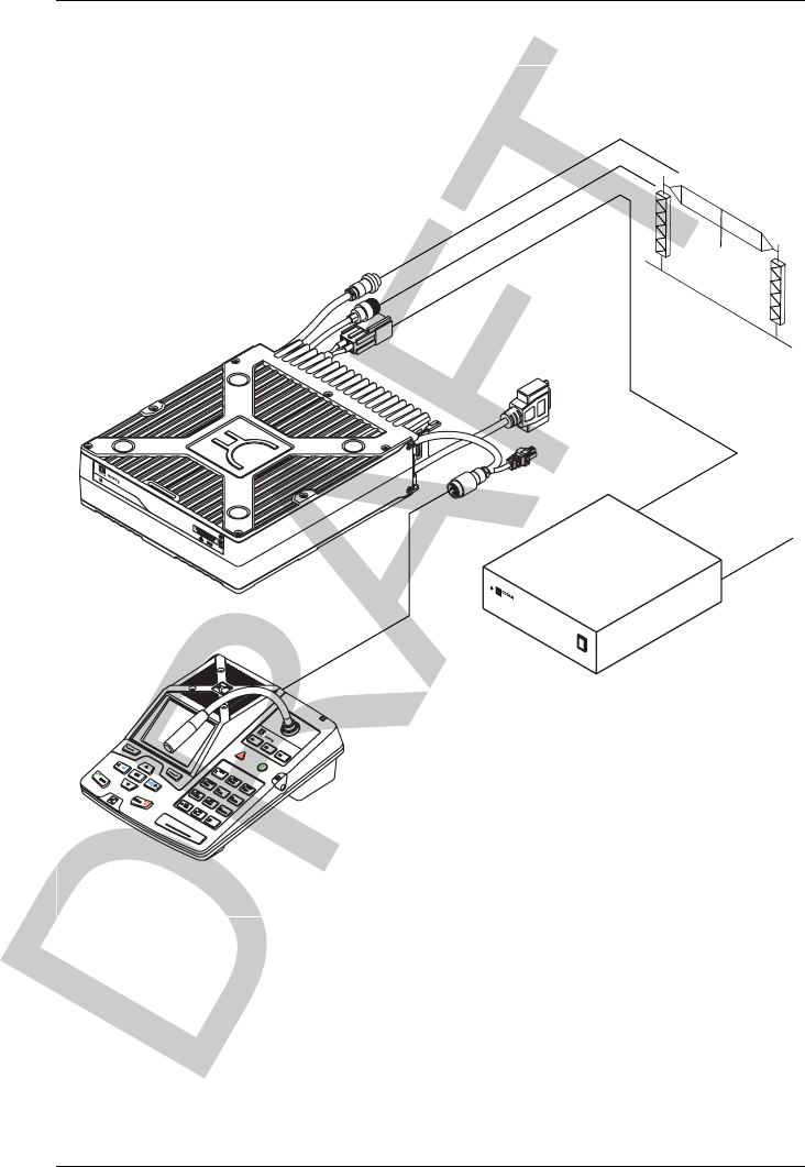
INSTALLING THE TRANSCEIVER
OVERVIEW OF FIXED STATIONS
ENVOY™ TRANSCEIVER GETTING STARTED GUIDE 115
Figure 28: Typical fixed station
NOTE: A range of ancillary equipment may be connected to
the Envoy™ Transceiver using the 6-way and
15-way connectors at the rear of the RFU.
RF Unit
™
Type 2210
Serial No.
antenna control
antenna
battery
RFU
10-way
connector
15-way
connector
6-way
connector
power supply AC mains
tuner
(optional)
broadband
antenna
Desk Console
™
desk console
08-07205-00x
08-03255
08-01503-00x
08-05627-00x
3020 Transceiver Supply

INSTALLING THE TRANSCEIVER
OVERVIEW OF FIXED STATIONS
116 ENVOY™ TRANSCEIVER GETTING STARTED GUIDE
Cables in a fixed station
Mounting a fixed Envoy™ station
A fixed Envoy™ station may be mounted using a 2230 Desk
Console. For general guidance on suitable locations for equipment
and installing the fixed station see the reference material on the
enclosed CD.
RFU and transceiver supply
The RFU and the transceiver supply are self-contained and are
usually stacked loosely. If you want to mount the RFU and/or the
transceiver supply, contact your Codan representative to obtain a
rack-mounting unit or the appropriate mounting cradles.
CAUTION: If you are mounting an RFU in a cradle, do not fit
rubber feet to the bottom of the RFU.
NOTE: If you are transferring a mobile station to a fixed
station, and you are not mounting the RFU in a
cradle, rubber feet can be fitted to the bottom of the
RFU. The rubber feet are available from Codan
(Codan part number 30-11208-000).
Table 6: Cables for a typical fixed Envoy™ station
Cable Symbol Part number
Cable between RFU and 2230 Desk Console 08-07205-xxx
Handset and speaker connector1 and cable
(optional)
08-06022-001
Coaxial cable between RFU and antenna208-01503-006
1. The part number for the cable corresponds to a standard 6 m cable.
2. The part number for the cable corresponds to a 30 m coaxial cable. The cable is also available in a
number of shorter lengths.

INSTALLING THE TRANSCEIVER
OVERVIEW OF FIXED STATIONS
ENVOY™ TRANSCEIVER GETTING STARTED GUIDE 117
Rack-mounting unit
A rack-mounting unit consists of a 19 inch rack tray. It can be used
to mount your fixed station with either a desk console or the
handset and cradle.
Connecting a fixed Envoy™ station
NOTE: A typical fixed station is shown in Figure 28.
To connect a fixed station:
Do one of the following:
• Connect cable 08-07205-00x between the
Transceiver connector on the 2230 Desk Console
and the 10-way plug on the flying lead from the
RFU, securing the locking rings tightly into position.
• Connect cable 08-07215-001 between the Ethernet
connector on the 2230 Desk Console, or an optional
switch/router, and the 10-way plug on the flying lead
from the RFU, securing the locking ring tightly into
position.
•If a switch/router is used, an additional RJ45 cable
is required to connect between the
switch/router and the desk console.
• Connect the lead from the handset and speaker
connector to the 10-way plug on the flying lead from
the RFU, then secure the locking ring tightly into
position.
If you are using the handset and speaker connector and
cable:
• Connect the plug of the handset cable to the socket
on the handset and speaker connector, then secure
the locking ring tightly into position.
• Connect the plug at the end of the speaker cable to
the socket on the handset and speaker connector,
then secure the cable by pushing it into the slot on the
side of the connector.

INSTALLING THE TRANSCEIVER
OVERVIEW OF FIXED STATIONS
118 ENVOY™ TRANSCEIVER GETTING STARTED GUIDE
Connect the plug at the end of the cable to the socket at the
end of the cable lead from the RFU, then secure the
locking ring tightly into position.
Connect the plug at the opposite end of the cable to the
socket located at the base of the antenna, then secure the
locking ring tightly into position.
Connecting an automatic tuner to the RFU and antenna
(optional)
NOTE: You may need to install a tuner to improve the
efficiency of the antenna in your fixed station (see
the reference material on the enclosed CD).
NOTE: The tuner used in most applications has connectors at
the end of the cables attached to the tuner, as
described below, however, you may have a tuner that
has sockets on the connector panel of the tuner.
To connect the tuner to the RFU:
Connect the plug at the end of the coaxial cable from the
tuner to the socket at the end of the cable lead from the
RFU, then secure the locking ring tightly into position.
Connect the plug at the end of the control cable from the
tuner to the socket at the end of the cable lead from the
RFU, then secure the locking ring tightly into position.
Connect the antenna to the antenna connector on the tuner,
then secure it tightly into position.

INSTALLING THE TRANSCEIVER
OVERVIEW OF FIXED STATIONS
ENVOY™ TRANSCEIVER GETTING STARTED GUIDE 119
Connecting the transceiver supply
To connect the transceiver to the transceiver supply:
Connect the DC output from the transceiver supply to the
plug at the end of the 12 V cable lead from the RFU.
Connect the transceiver supply to the AC mains supply.

INSTALLING THE TRANSCEIVER
OVERVIEW OF FIXED STATIONS
120 ENVOY™ TRANSCEIVER GETTING STARTED GUIDE
This page has been left blank intentionally.

ENVOY™ TRANSCEIVER GETTING STARTED GUIDE 121
BCompliance
This section contains the following topics:
•Overview on page 122
•European R&TTE Directive on page 123
•EMC and safety notices on page 126
•FCC compliance on page 130
•IC certification on page 131
•RCM approval on page 132

COMPLIANCE
OVERVIEW
122 ENVOY™ TRANSCEIVER GETTING STARTED GUIDE
Overview
This section describes how to ensure the Envoy™ Transceiver
complies with the European R&TTE Directive 1999/5/EC.
This section also contains the requirements for RCM.

COMPLIANCE
EUROPEAN R&TTE DIRECTIVE
ENVOY™ TRANSCEIVER GETTING STARTED GUIDE 123
European R&TTE Directive
The Envoy™ Transceiver has been tested and complies with the
following standards and requirements (articles of the R&TTE
Directive):
• Article 3.1b: ETSI EN 301 489-1 V1.8.1
• Article 3.1b: ETSI EN 301 489-15 V1.2.1
• Article 3.2: Australian type approval according to AS/NZS
4770:2000 + transmitter RSE tests to the limits specified in
Annex 6, section 6.1.2 of CEPT/ERC/Recommendation
74-01E
• Article 3.1a: assessed against ICNIRP and FCC
requirements
• Article 3.1a: (LVD) EN 60950-1:2006/AC:2011
• Article 3.1a: (MPE) EN 62311:2008
Product marking and labelling
Any equipment supplied by Codan that satisfies these requirements
is identified by the markings displayed on the product.
Radiation safety (EU installations only)
To ensure optimal transceiver performance and to avoid exposure
to excessive electromagnetic fields, the antenna system must be
installed according to the instructions provided.
WARNING: High voltages exist on the antenna during
transmission and tuning. Do not touch the antenna
during these activities. RF burns may result.
WARNING: Install the grounding system or counterpoise as
directed to prevent RF burns from any metal part of
the transceiver.

COMPLIANCE
EUROPEAN R&TTE DIRECTIVE
124 ENVOY™ TRANSCEIVER GETTING STARTED GUIDE
WARNING: You should not transmit from your transceiver or
tune the antenna unless people are beyond the safe
working distance for the installation.
The following safe working distances apply:
• anywhere within the vehicle cabin with externally mounted
mobile antenna
• 3 m unobstructed, of any part of a mobile antenna
• 2 m of any part of a fixed antenna
Safe working distance is based on continuous exposure to CW-type
transmissions, as set out in the Human Exposure Restrictions
standard EN 62311:2008.
Declaration of Conformity and Notified Body Letter
of Opinion
The CE Declaration of Conformity and Notified Body Letter of
Opinion for this product are available upon request to Codan or a
Codan-authorised supplier.
Protection of the radio spectrum
CAUTION: Most countries restrict the use of HF radio
communications equipment to certain frequencies
and bandwidths and/or require such equipment to be
licensed. It is the user’s responsibility to check the
specific requirements with the appropriate
communications authorities. Some options may vary
the stated compliance. If necessary, contact Codan
for more information.
The receive and transmit frequencies may be any frequencies
within the HF range, however, the transmit frequencies can only be
those allocated to you by the relevant government authority in your
country.

COMPLIANCE
EUROPEAN R&TTE DIRECTIVE
ENVOY™ TRANSCEIVER GETTING STARTED GUIDE 125
Spectral regulations may require the TxD option to be installed in
the transceiver. In this case, you cannot add channels with new
transmit frequencies. You can, however, add receive-only
channels, and channels with the same transmit frequency as an
existing channel. If the TxP option is installed in the transceiver,
you cannot add channels.

COMPLIANCE
EMC AND SAFETY NOTICES
126 ENVOY™ TRANSCEIVER GETTING STARTED GUIDE
EMC and safety notices
Radiation safety (non-EU installations)
To ensure optimal transceiver performance and to avoid exposure
to excessive electromagnetic fields, the antenna system must be
installed according to the instructions provided.
WARNING: High voltages exist on the antenna during
transmission and tuning. Do not touch the antenna
during these activities. RF burns may result.
WARNING: Install the grounding system or counterpoise as
directed to prevent RF burns from any metal part of
the transceiver.
WARNING: You should not transmit from your transceiver or
tune the antenna unless people are beyond the safe
working distance for the installation.
The following safe working distances apply:
• anywhere within the vehicle cabin with an externally
mounted mobile antenna
•1.8m (
ft) unobstructed, of any part of a mobile antenna
•2
m (7 ft) of any part of a fixed antenna in a data installation
of up to 125 W output
• 5 m (17 ft) of any part of a fixed antenna in a data
installation of up to 1 kW output
Safe working distance is based on continuous exposure to CW-type
transmissions, as set out in the ICNIRP Exposure Guidelines
(1998) for occupational exposure. Safe working distance can be
reduced with normal voice communication.

COMPLIANCE
EMC AND SAFETY NOTICES
ENVOY™ TRANSCEIVER GETTING STARTED GUIDE 127
Sécurité des radiations (installations non-EU)
Pour assurer la performance optimale de l’émetteur-récepteur et
pour éviter une exposition excessive aux champs
électromagnétiques, le système d’antenne doit être déployé selon
les instructions fournies.
Les distances de sécurité suivantes sont applicables :
• à l’intérieur de la cabine d’un véhiclue sur lequel une
antenne mobile est deployée
• 1.8 m sans obstruction, de n’importe quelle partie de
l’antenne mobile
• 2 m de n’importe quelle partie de l’antenne fixe dans une
installation de données dont la sortie peut atteindre 125 W
• 5 m de n’importe quelle partie de l’antenne fixe dans une
installation de données dont la sortie peut atteindre 1 kW
La distance de sécurité du travail se base sur une exposition
continue aux transmissions de type onde entretenue, telle
qu’établie dans les Lignes directives d’exposition de l’ICNIRP
(1998) pour l’exposition au travail. La distance de sécurité du
travail peut être réduite dans le cas de communications vocales
normales.
ATTENTION: De hautes tensions RF sont présentes au
cours de la transmission et de la
syntonisation. Ne touchez pas l’antenne
pendant ces activités, au risque de vous
brûler.
ATTENTION: Installez le système de prise de terre ou le
contrepoids comme prescrit pour éviter
toute brûlure RF au contact des pièces
métalliques de l’émetteur-récepteur.
ATTENTION: Evitez d’émettre à partir de votre
émetteur-récepteur onde syntoniser
l’antenne si quelqu’un se trouve à moins
de la distance de sécurité.

COMPLIANCE
EMC AND SAFETY NOTICES
128 ENVOY™ TRANSCEIVER GETTING STARTED GUIDE
EMC
CAUTION: If it is necessary to remove the covers at any stage,
they must be refitted correctly before using the
equipment.
To ensure that compliance with the EMC Directive is maintained.
Use standard shielded cables supplied from Codan (where
applicable).
Ensure the covers for the equipment are fitted correctly.
Cover unused connectors on the RFU with the protective
caps supplied to prevent electrostatic discharge passing
through your transceiver.
Electrical safety
To ensure compliance with the European Low Voltage Directive is
maintained, you must install and use the Envoy™ Transceiver in
accordance with the instructions in the Envoy™ Transceiver
Getting Started Guide and the Envoy™ Transceiver Reference
Manual.
When using equipment that is connected directly to the AC mains
these precautions must be followed and checked before applying an
AC mains supply to the unit.
To ensure electrical safety:
Use the standard AC mains cable supplied.
Ensure the covers for the equipment are fitted correctly.
CAUTION: If it is necessary for a qualified electronics technician
to remove the covers during servicing, they must be
refitted correctly before using the equipment.
WARNING: A protective earth connection must be included in
the mains wiring to the 3020 Transceiver Supply.

COMPLIANCE
EMC AND SAFETY NOTICES
ENVOY™ TRANSCEIVER GETTING STARTED GUIDE 129
WARNING: The protective cover must always be fitted when the
3020 Transceiver Supply is connected to the AC
mains.
Related links:
Earth symbols on page 129
Earth symbols
Chassis earth connection points are provided on the Envoy™
Transceiver and 3020 Transceiver Supply. A protective earth is
provided in the AC mains wiring of the 3020 Transceiver Supply.
This protective earth must be connected at the AC mains supply
outlet. The symbols shown below are used to identify the earths on
the equipment.
Table 7: Earth symbols
Symbol Meaning
Chassis earth
Protective earth

COMPLIANCE
FCC COMPLIANCE
130 ENVOY™ TRANSCEIVER GETTING STARTED GUIDE
FCC compliance
FCC Part 90 certification
The Envoy™ Transceiver has been tested and certified to FCC
Part 90 (FCC identifier code DYY2210).
FCC Part 15 compliance
Any modifications made to the Envoy™ Transceiver and 3020
Transceiver Supply that are not approved by the party responsible
for compliance may void your equipment’s compliance under
Part 15 of the FCC rules.
The Envoy™ Transceiver and 3020 Transceiver Supply have been
tested and found to comply with the limits for a Class B device,
pursuant to Part 15 of the FCC rules. These limits are designed to
provide reasonable protection against harmful interference in a
residential installation. This equipment generates, uses and can
radiate radio frequency energy and, if not installed and used in
accordance with the instructions, may cause harmful interference
to radio communications. However, there is no guarantee that
interference will not occur in a particular installation. If this
equipment does cause harmful interference to radio or television
reception, which can be determined by switching the equipment off
and on, the user is encouraged to try to correct the interference by
one or more of the following measures:
• reorient or relocate the receiving antenna
• increase the separation between the equipment and receiver
• connect the equipment into an outlet on a circuit different
from that to which the receiver is connected
• consult the dealer or an experienced radio/TV technician for
help

COMPLIANCE
IC CERTIFICATION
ENVOY™ TRANSCEIVER GETTING STARTED GUIDE 131
IC certification
Product markings and labelling
The Envoy™ Transceiver is certified to IC standards (IC identifier
1029A-1).
L’émetteur-récepteur Envoy™ est certifié conforme aux normes
IC (Code d’identification IC : 1029A-1).

COMPLIANCE
RCM APPROVAL
132 ENVOY™ TRANSCEIVER GETTING STARTED GUIDE
RCM approval
The Envoy™ Transceiver meets the requirements of the Australian
Communications and Media Authority: Radiocommunications
(MF and HF equipment—Land Mobile Service) Standard 2003
(AS/NZS 4770) and Radiocommunications (HF CB and
Handphone Equipment) Standard 2008 (AS/NZ 4355).

INDEX
ENVOY™ TRANSCEIVER GETTING STARTED GUIDE INDEX -1
Index
Numerics
2220 Handset 3
2221 Handset 5
entering text 47
2230 Desk Console 7
A
advanced view 36
antenna
manual tune 9
selecting 29
B
basic view 36
brightness
setting 70
C
call
adding from the Call Log/Call History 102
adding to contact
Channel Test 23,96
Emergency 23,96
Get Position 23,96
Get Status 27,99
Message 24,97
Phone 26,98
RFDS Emergency 100
Selective 23,96
Send Position 23,96
from Emergency key 8
making
Message 73
Selective 71
to a contact 76
call information
structure 58
channel
adding 19
capacity 105
finding 64
scr een 61
selecting 63
Channel Test call
adding to contact 23,96
character-entry mode
selecting 10
check box
selecting/deselecting 50
clarifier 9
compliance 121
EMC and safety notices
earth symbols 129
electrical safety 128
EMC 128
radiation safety (non-EU) 126
sécurité des radiations (non-EU) 127
FCC 130
IC certification 131
overview 122
R&TTE 123
declaration of conformity and notified
body letter of opinion 124
product marking and labelling 123
protection of the radio spectrum 124
radiation safety (EU only) 123
RCM approval 132
contact
add ing Channel Test call 23

INDEX
INDEX- 2
adding 22,94
adding Channel Test call 96
adding Emergency call 23,96
adding from the Call Log/Call History 102
adding Get Position call 23,96
adding Get Status call 27,99
adding Message call 24,97
adding Phone call 26,98
adding RFDS Emergency call 100
adding Selective call 23,96
adding Send Position call 23,96
cooling 105
crosspatch
operating mode 9
changing 90
overview 88
D
data rate
selecting 86
date
setting 17,69
deleting items 42
desk console
location 18
size 106
weight 106
display
brightness 70
E
Easitalk 10
editing items 42
Emergency call
adding to contact 23,96
encryptor
switching on/off 81
F
firmware upgrade
USB stick 91
fixed station 114
free-tune
receive 9
frequency
range 105
G
Get Position call
adding to contact 23,96
Get Status call
adding to contact 27,99
GPS
information
using 79
H
handset
size 106
weight 106
I
icon
selecting 41
K
keypad 8
L
language
selecting 17
M
menu bar
selecting an option 42
menu structure
navigating 31
Message call
adding to contact 24,97
making 73
microphone
using 68
mobile station 108
mode
changing 63
selecting 9
moving items 42,52
mute 67
switching on or off 67
mute type
selecting 67
O
operating modes 105
order of items in a list
changing 52

INDEX
INDEX-3
P
peripheral
selecting 30
Phone call
adding to contact 26,98
program profile
USB stick 91
program secure keys
USB stick 91
R
read profile
USB stick 91
relative humidity 105
RFDS Emergency call
adding to contact 100
RFU
size 106
weight 106
S
scanning 65
pausing 66
switching on or off 65
screen
channel 61
secure
standby mode 83
secure key
adding 85
selecting 84
secure mode 10
Selective call
adding to contact 23,96
making 71
self address
entering 21
Send Position call
adding to contact 23,96
size
desk console 106
handset 106
RFU 106
slider
moving 51
special characters
entering 10
station
fixed 114
cables 116
mobile 108
cables 110
connecting control cable to automatic
tuning antenna 112
connecting to battery power supply 113
mounting 110
mounting handset and speaker connector
111
mounting handset cradle 110
mounting RF unit 111
mounting speaker 111
T
temperature 105
text
editing 44
time
setting 17,69
transceiver
installing 107
operating 59
switching off 60
switching on 60
U
USB stick 91
user information
structure 56
V
value
finding 38
view
advanced 36
basic 36
overview 36
switching between 37
W
weight
desk console 106
handset 106
RFU 106
wizard
adding channels to a scan table 20
overview 14
starting 16
word
finding 38

INDEX
INDEX- 4
This page has been left blank intentionally.

ASIA PACIFIC (Head Office)
Codan Limited
81 Graves Street
Newton SA 5074
AUSTRALIA
T: +61 8 8305 0311
F: +61 8 8305 0411
asiasales@codanradio.com
EUROPE, MIDDLE-EAST & AFRICA
Codan (UK) Ltd
Unit C4, Endeavour Place
Coxbridge Business Park
Farnham Surrey GU10 5EH
UNITED KINGDOM
T: +44 1252 717 272
F: +44 1252 717 337
uksales@codanradio.com
AMERICAS
Codan US, Inc.
1 Fishers Road
Pittsford NY 14534
USA
T: +1 585 419 9970
F: +1 585 419 9971
ussales@codanradio.com
www.codanradio.com