Codan NGT-11 HF SSB Transceiver User Manual 15 04127 EN 6
Codan Limited HF SSB Transceiver 15 04127 EN 6
Codan >
Contents
- 1. User Manual 2010 2011
- 2. User Manual 2012
User Manual 2010 2011

HF RADIO COMMUNICATIONS
GETTING STARTED GUIDE
NGT Transceiver
No part of this guide may be reproduced, transcribed,
translated into any language or transmitted in any form
whatsoever without the prior written consent of Codan
Limited.
© Copyright 2003, 2004, 2005 Codan Limited.
Codan part number 15-04127-EN Issue 6, June 2005
NGT® and CALM® are registered trademarks of Codan
Limited. Other brand, product, and company names
mentioned in this document are trademarks or registered
trademarks of their respective holders.
The English version takes precedence over any translated
versions.

NGT Transceiver Getting Started Guide i
CODAN
Table of contents
Introduction
Overview of this guide . . . . . . . . . . . . . . . . . . . . . . . . . . . . . . . . . . . . . . 1
Accessing the CD . . . . . . . . . . . . . . . . . . . . . . . . . . . . . . . . . . . . . . . . . . 2
1 NGT transceiver compliance
Introduction. . . . . . . . . . . . . . . . . . . . . . . . . . . . . . . . . . . . . . . . . . . . . . . . . . 4
European Radio and Telecommunications Terminal Equipment
Directive . . . . . . . . . . . . . . . . . . . . . . . . . . . . . . . . . . . . . . . . . . . . . . . . . . . . 5
Electromagnetic compatibility and safety notices . . . . . . . . . . . . . . . . . . . . 7
FCC compliance . . . . . . . . . . . . . . . . . . . . . . . . . . . . . . . . . . . . . . . . . . . . . 11
2 Installation
Mobile stations for NGT AR, SR, AR Voice, and VR Transceivers . . . . . . 14
Cables . . . . . . . . . . . . . . . . . . . . . . . . . . . . . . . . . . . . . . . . . . . . . . . . . . 17
Mounting a mobile NGT station . . . . . . . . . . . . . . . . . . . . . . . . . . . . . . 17
Connecting a mobile NGT station. . . . . . . . . . . . . . . . . . . . . . . . . . . . . 20
Fixed stations for NGT AR, SR, AR Voice, and VR Transceivers. . . . . . . . 23
Cables . . . . . . . . . . . . . . . . . . . . . . . . . . . . . . . . . . . . . . . . . . . . . . . . . . 26
Mounting a fixed NGT station . . . . . . . . . . . . . . . . . . . . . . . . . . . . . . . 27
Connecting a fixed NGT station . . . . . . . . . . . . . . . . . . . . . . . . . . . . . . 28
3 The handset
Hot keys . . . . . . . . . . . . . . . . . . . . . . . . . . . . . . . . . . . . . . . . . . . . . . . . . . . 34
The channel screen . . . . . . . . . . . . . . . . . . . . . . . . . . . . . . . . . . . . . . . . . . . 36
4 Getting started
Switching on the transceiver. . . . . . . . . . . . . . . . . . . . . . . . . . . . . . . . . . . . 38
Switching off the transceiver . . . . . . . . . . . . . . . . . . . . . . . . . . . . . . . . 38
Setting up basics . . . . . . . . . . . . . . . . . . . . . . . . . . . . . . . . . . . . . . . . . . . . . 39
Selecting a channel . . . . . . . . . . . . . . . . . . . . . . . . . . . . . . . . . . . . . . . . . . . 40
Making a basic voice call . . . . . . . . . . . . . . . . . . . . . . . . . . . . . . . . . . . . . . 41

Table of contents
ii NGT Transceiver Getting Started Guide
Making a Selective call . . . . . . . . . . . . . . . . . . . . . . . . . . . . . . . . . . . . . . . . 42
Scanning channels . . . . . . . . . . . . . . . . . . . . . . . . . . . . . . . . . . . . . . . . . . . . 44
Switching scanning on or off . . . . . . . . . . . . . . . . . . . . . . . . . . . . . . . . . 44
Pausing scanning . . . . . . . . . . . . . . . . . . . . . . . . . . . . . . . . . . . . . . . . . . 45
Appendix A—Entering and editing text
Editing a screen . . . . . . . . . . . . . . . . . . . . . . . . . . . . . . . . . . . . . . . . . . . 47
Entering text. . . . . . . . . . . . . . . . . . . . . . . . . . . . . . . . . . . . . . . . . . . . . . 48
Changing between alpha and numerical characters . . . . . . . . . . . . . . . . 49
Moving the cursor . . . . . . . . . . . . . . . . . . . . . . . . . . . . . . . . . . . . . . . . . 49
Inserting text . . . . . . . . . . . . . . . . . . . . . . . . . . . . . . . . . . . . . . . . . . . . . 49
Deleting text. . . . . . . . . . . . . . . . . . . . . . . . . . . . . . . . . . . . . . . . . . . . . . 50
Saving text changes . . . . . . . . . . . . . . . . . . . . . . . . . . . . . . . . . . . . . . . . 50
Appendix B—Using Quick Start
Appendix C—Using a GPS receiver
Appendix D—Transceiver specifications
Appendix E—HF radio transmission
Frequency, distance and time of day . . . . . . . . . . . . . . . . . . . . . . . . . . . 64
Channels and modes. . . . . . . . . . . . . . . . . . . . . . . . . . . . . . . . . . . . . . . . 65
Networks and scanning . . . . . . . . . . . . . . . . . . . . . . . . . . . . . . . . . . . . . 66
Etiquette for the use of HF radio . . . . . . . . . . . . . . . . . . . . . . . . . . . . . . 66
Appendix F—Definitions
Standards and icons . . . . . . . . . . . . . . . . . . . . . . . . . . . . . . . . . . . . . . . . . . . 69
Acronyms and abbreviations . . . . . . . . . . . . . . . . . . . . . . . . . . . . . . . . . . . . 70
Glossary . . . . . . . . . . . . . . . . . . . . . . . . . . . . . . . . . . . . . . . . . . . . . . . . . . . . 72
Units. . . . . . . . . . . . . . . . . . . . . . . . . . . . . . . . . . . . . . . . . . . . . . . . . . . . . . . 76
Unit multipliers . . . . . . . . . . . . . . . . . . . . . . . . . . . . . . . . . . . . . . . . . . . . . . 76
About this issue . . . . . . . . . . . . . . . . . . . . . . . . . . . . . . . . . . . . . . . . . . . . . . 77
Index

NGT Transceiver Getting Started Guide iii
CODAN
List of figures
Figure 1: Typical mobile NGT AR or SR station . . . . . . . . . . . . . . 15
Figure 2: Typical mobile NGT AR Voice or VR station. . . . . . . . . 16
Figure 3: Typical fixed NGT AR or SR station . . . . . . . . . . . . . . . 24
Figure 4: Typical fixed NGT AR Voice or VR station . . . . . . . . . . 25
Figure 5: The handset. . . . . . . . . . . . . . . . . . . . . . . . . . . . . . . . . . . 31
Figure 6: The channel screen in the Channel List . . . . . . . . . . . . . 36
Figure 7: The reflective properties of the ionosphere . . . . . . . . . . 64

List of figures
iv NGT Transceiver Getting Started Guide
This page has been left blank intentionally.

NGT Transceiver Getting Started Guide v
CODAN
List of tables
Table 1: Earth symbols . . . . . . . . . . . . . . . . . . . . . . . . . . . . . . . . . 10
Table 2: Cables for a typical mobile NGT station . . . . . . . . . . . . 17
Table 3: Cables for a typical fixed NGT station. . . . . . . . . . . . . . 26
Table 4: Standard hot keys . . . . . . . . . . . . . . . . . . . . . . . . . . . . . . 34
Table 5: NGT Transceiver specifications. . . . . . . . . . . . . . . . . . . 61
Table 6: Examples of channels and modes. . . . . . . . . . . . . . . . . . 65
Table 7: The phonetic alphabet. . . . . . . . . . . . . . . . . . . . . . . . . . . 67

List of tables
vi NGT Transceiver Getting Started Guide
This page has been left blank intentionally.

NGT Transceiver Getting Started Guide 1
CODAN
Introduction
Thank you for purchasing a Codan NGT Transceiver. With this
great product and Codan’s supreme after-sales support, you
can look forward to many years of clear and reliable HF
communication. Please read this guide thoroughly and retain it
for future reference. There is an index at the end of this guide
to assist you in finding information.
Overview of this guide
This guide provides instructions on how to connect up your
NGT AR, SR, AR Voice, or VR Transceiver, and how to
perform basic setup and operating tasks. It assumes that you
have limited knowledge of HF communication and of using an
HF transceiver.
Extensive reference material is provided on the CD at the back
of this guide.
This guide contains the following sections:
Section 1 NGT transceiver compliance—provides
compliance information and safety notices for
your transceiver
Section 2 Installation—explains briefly how to connect
the components of your transceiver
Section 3 The handset—describes the handset and the
function of items on the handset
Section 4 Getting started—explains how to use the basic
operating features of your transceiver
Appendix A Entering and editing text—explains how to
enter and edit text in editable screens
Appendix B Using Quick Start—explains how to use the
Quick Start feature, if enabled
Appendix C Using a GPS receiver—explains the
information provided by the GPS receiver, if
fitted

Introduction
2 NGT Transceiver Getting Started Guide
Appendix D Transceiver specifications—provides the
common operational specifications of the
transceiver
Appendix E HF radio transmission—describes the medium
of HF communication and how to use it
effectively
Appendix F Definitions—explains the terms and
abbreviations used in this guide
Accessing the CD
To access the CD:
1Place the CD in the CD drive of your computer.
The CD will automatically launch the NGT Transceiver
Reference Manual as a fully text-searchable HTML help
file.


NGT transceiver compliance
4 NGT Transceiver Getting Started Guide
Introduction
This section describes how to ensure the NGT transceiver
complies with the European Electromagnetic Compatibility
Directive 89/336/EEC and the European Low Voltage
Directive 73/23/EEC as called up in the European Radio and
Telecommunications Terminal Equipment Directive
1999/5/EC.
The CE Declarations of Conformity and Expert Letters of
Opinion for the product range are listed on page 77,
Associated documents. These documents can be made
available upon request to Codan or a Codan-authorised
supplier.
This section also contains the requirements for FCC
compliance.
NGT transceiver compliance
NGT Transceiver Getting Started Guide 5
European Radio and Telecommunications
Terminal Equipment Directive
The NGT transceiver product range has been tested and
complies with the following standards and requirements
(articles of the R&TTE Directive):
• Article 3.1b: ETSI EN 301 489-1
• Article 3.1b: ETSI EN 301 489-15
• Article 3.2: Australian type approval according to
ECR 209
• Article 3.1a: assessed against ICNIRP and FCC
requirements
• Article 3.1a: EN 60950
Product marking and labelling
Any equipment supplied by Codan that satisfies these
requirements is identified by the , or
markings on the model label of the product.
Declaration of Conformity and Expert Letter of
Opinion
The CE Declarations of Conformity and Expert Letters of
Opinion for this product range are listed on page 77,
Associated documents. These documents can be made
available upon request to Codan or a Codan-authorised
supplier.
0191 0191

NGT transceiver compliance
6 NGT Transceiver Getting Started Guide
Protection of the radio spectrum
CAUTION
Most countries restrict the use of HF radio
communications equipment to certain frequency
bands and/or require such equipment to be
licensed. It is the user’s responsibility to check
the specific requirements with the appropriate
communications authorities. If necessary,
contact Codan for more information.

NGT transceiver compliance
NGT Transceiver Getting Started Guide 7
Electromagnetic compatibility and safety
notices
Radiation safety
To ensure optimal transceiver performance and to avoid
exposure to excessive electromagnetic fields, the antenna
system must be installed according to the instructions
provided.
Safe working distance is based on continuous exposure to CW
type transmissions, as set out in the ICNIRP Exposure
Guidelines (1998) for occupational exposure. Safe working
distance can be reduced with normal voice communication.
WARNING
High voltages exist on the antenna during
transmission and tuning. Do not touch the
antenna during these activities. RF burns may
result.
WARNING
Install the grounding system or counterpoise as
directed to prevent RF burns from any metal
part of the transceiver.
WARNING
You should not transmit from your transceiver
or tune the antenna unless people are beyond the
safe working distance of:
• 1.5 m (5 ft) of any part of a mobile antenna
• 2 m (7 ft) of any part of a fixed antenna in a
data installation of up to 125 W output
• 5 m (17 ft) of any part of a fixed antenna in a
data installation of up to 1 kW output

NGT transceiver compliance
8 NGT Transceiver Getting Started Guide
Electromagnetic compatibility
To ensure compliance with the EMC Directive is maintained,
you must:
1Use standard shielded cables supplied from Codan
(where applicable).
1Ensure the covers for the equipment are fitted correctly.
1Cover unused connectors on the junction box (if fitted)
and RF unit with the protective caps supplied to prevent
electrostatic discharge passing through your NGT
equipment.
CAUTION
If it is necessary to remove the covers at
any stage, they must be refitted correctly
before using the equipment.

NGT transceiver compliance
NGT Transceiver Getting Started Guide 9
Electrical safety
To ensure compliance with the European Low Voltage
Directive is maintained, you must install and use the
NGT transceiver in accordance with the instructions in the
NGT Transceiver Getting Started Guide and the NGT
Transceiver Reference Manual.
When using equipment that is connected directly to the AC
mains these precautions must be followed and checked before
applying AC power to the unit:
1Use the standard AC mains cable supplied.
1Ensure the covers for the equipment are fitted correctly.
CAUTION
If it is necessary for a qualified electronics
technician to remove the covers during
servicing, they must be refitted correctly
before using the equipment.
WARNING
A protective earth connection must be
included in the mains wiring to the 3020
Transceiver Supply (see below, Earth
symbols).
The protective cover must always be fitted
when the 3020 Transceiver Supply is
connected to the AC mains.
NGT transceiver compliance
10 NGT Transceiver Getting Started Guide
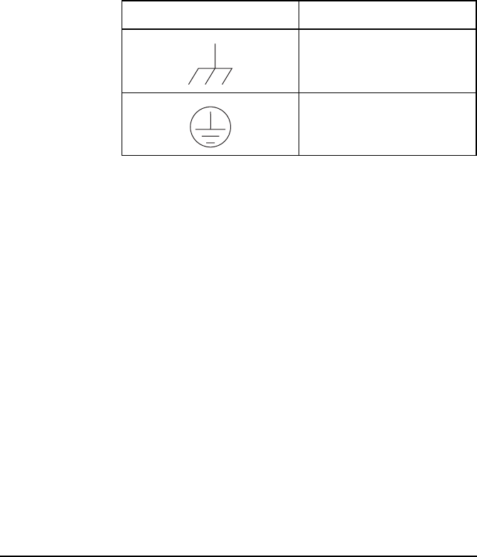
Earth symbols
Chassis earth connection points are provided on the
NGT transceiver and 3020 Transceiver Supply. A protective
earth is provided in the AC mains wiring of the 3020
Transceiver Supply. This protective earth needs to be
connected at the AC mains supply outlet. The symbols shown
in Table 1 are used to identify the earths on the equipment.
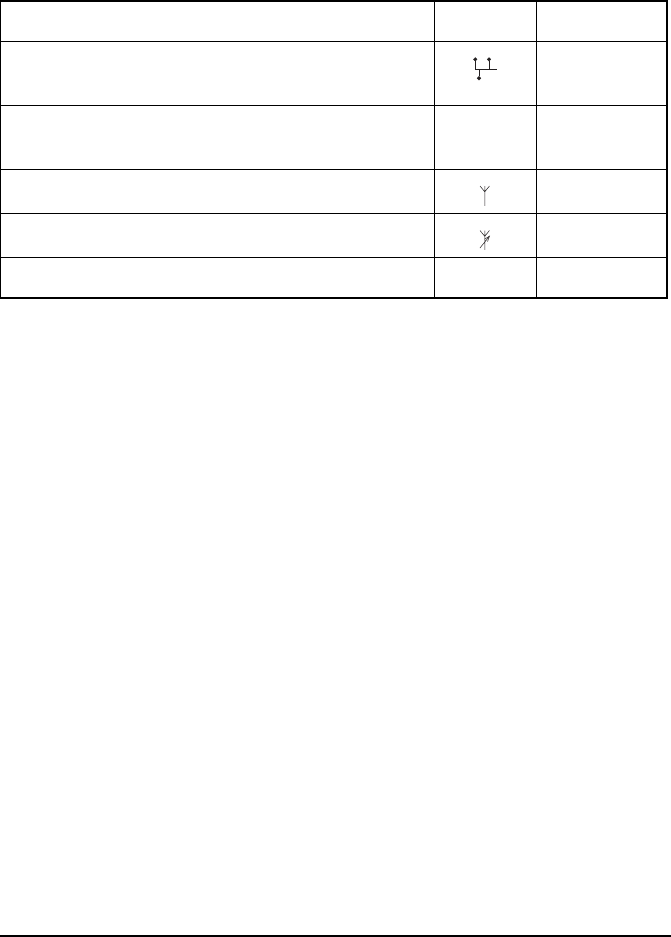
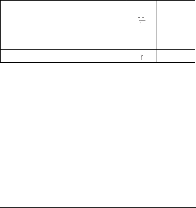
Table 1: Earth symbols
Symbol Meaning
Chassis earth
Protective earth

NGT transceiver compliance
NGT Transceiver Getting Started Guide 11
FCC compliance
FCC Part 90 certification
The NGT SR Transceiver has been tested and certified to FCC
Part 90 (FCC identifier code DYYNGT-1).
FCC Part 15 compliance
Any modifications made to the NGT SR Transceiver and 3020
Transceiver Supply that are not approved by the party
responsible for compliance may void your equipment’s
compliance under Part 15 of the FCC rules.
The NGT SR Transceiver and 3020 Transceiver Supply have
been tested and found to comply with the limits for a Class B
device, pursuant to Part 15 of the FCC rules. These limits are
designed to provide reasonable protection against harmful
interference in a residential installation. This equipment
generates, uses and can radiate radio frequency energy and, if
not installed and used in accordance with the instructions, may
cause harmful interference to radio communications.
However, there is no guarantee that interference will not occur
in a particular installation. If this equipment does cause
harmful interference to radio or television reception, which
can be determined by switching the equipment off and on, the
user is encouraged to try to correct the interference by one or
more of the following measures:
• reorient or relocate the receiving antenna
• increase the separation between the equipment and
receiver
• connect the equipment into an outlet on a circuit different
from that to which the receiver is connected
• consult the dealer or an experienced radio/TV technician
for help

NGT transceiver compliance
12 NGT Transceiver Getting Started Guide
This page has been left blank intentionally.


Installation
14 NGT Transceiver Getting Started Guide
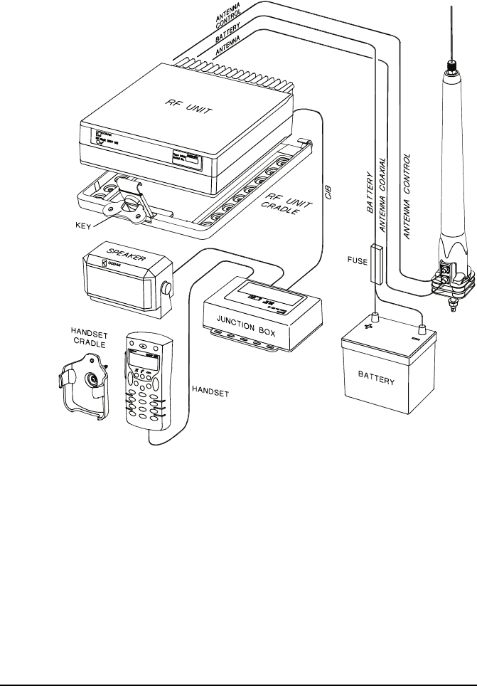
Mobile stations for NGT AR, SR, AR Voice,
and VR Transceivers
A mobile NGT station typically consists of:
• a handset and cradle
• a junction box (NGT AR and SR Transceivers only)
• a speaker
• an RF unit and vehicle mounting cradle (includes DC
power cable)
• a 12 V DC power supply (battery)
• an automatic tuning antenna
Figure 1 on page 15 shows a typical mobile NGT AR or SR
station.
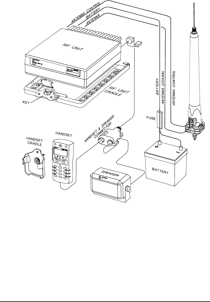
Figure 2 on page 16 shows a typical mobile NGT AR Voice or
VR station.
Installation
NGT Transceiver Getting Started Guide 15
Figure 1: Typical mobile NGT AR or SR station
9350 ANTENNA
Installation
16 NGT Transceiver Getting Started Guide
Figure 2: Typical mobile NGT AR Voice or VR station
9350 ANTENNA
4-WAY
CONNECTOR
10-WAY
CONNECTOR
Installation
NGT Transceiver Getting Started Guide 17
Cables
Mounting a mobile NGT station
Most components of a mobile NGT AR, SR, AR Voice, and VR
station are provided with their own mounting cradles. For
general guidance on suitable locations for equipment and
installing these stations see the reference material on the
enclosed CD.
Mounting the handset cradle
To mount the handset cradle:
1Mount the handset according to the fitting instructions
(Codan part number 15-00129-001) provided with the
handset cradle.
Table 2: Cables for a typical mobile NGT station
Cable Symbol Part number
CIB cable between RF unit and junction boxa (NGT
AR and SR Transceivers only)
a. The part number for this cable corresponds to a standard 6 m CIB cable. The cable is also
available in a number of shorter and longer lengths.
08-05610-006
Handset and speaker connector cableb (NGT
AR Voice and VR Transceivers only)
b. The part number for the cable corresponds to a standard 6 m cable.
08-06022-001
Coaxial cable between RF unit and antennac
c. The part number for the cable corresponds to a standard 6 m cable. The cable is also available
in a number of shorter and longer lengths.
08-01503-006
Control cable between RF unit and antennac08-05627-006
DC power supply cableb08-03255

Installation
18 NGT Transceiver Getting Started Guide
Mounting the speaker
To mount the speaker:
1Secure the mounting cradle to the surface with at least
two screws.
Ensure there is sufficient space at the rear for the cable.
1Attach the speaker to the cradle with the two screws and
rubber washers.
Mounting the junction box (NGT AR and
SR Transceivers only)
To mount the junction box:
1Use cable ties or screws to secure the junction box in a
suitable location.
Mounting the handset and speaker connector (NGT
AR Voice and VR Transceivers only)
To mount the handset and speaker connector:
1Use cable ties or screws to secure the handset and
speaker connector in a suitable location.

Installation
NGT Transceiver Getting Started Guide 19
Mounting the RF unit
To mount the RF unit:
1Secure the mounting cradle to the surface with at least
four screws, one in each corner of the cradle.
1If the key is locked to the base of the cradle, flip the key
away from the base until it can be rotated (see
Figure 1 on page 15), then rotate the key in a
counterclockwise direction.
1Place the RF unit into the cradle and push it under the
tabs at the rear of the cradle, then hold the clamp against
the front of the RF unit.
1Rotate the key clockwise, then push the key toward the
base of the cradle to lock the RF unit into position.
WARNING
If you are transferring a fixed station to a mobile
station and you have installed rubber feet to the
bottom of the RF unit, you must remove the
rubber feet before installing it into the mounting
cradle.
NOTE Ensure there is sufficient space at the rear
of the cradle to clear the RF unit heatsink.
Installation
20 NGT Transceiver Getting Started Guide
Connecting a mobile NGT station
Connecting a mobile NGT AR or SR station
To connect a mobile NGT AR or SR station:
1Connect the plug of the handset cable to the socket on
the junction box, then secure the locking ring tightly into
position.
1Connect the plug at the end of the speaker cable to the
socket on the junction box.
1Connect the socket at the end of the cable to the plug
at the end of the cable lead from the RF unit, then
secure the locking ring tightly into position.
1Connect the socket at the opposite end of the cable to
the plug on the junction box, then secure the locking
ring tightly into position.
1Connect the plug at the end of the cable to the socket at
the end of the cable lead from the RF unit, then secure
the locking ring tightly into position.
1Connect the plug at the opposite end of the cable to the
socket located at the base of the antenna, then secure the
locking ring tightly into position.

Installation
NGT Transceiver Getting Started Guide 21
Connecting a mobile NGT AR Voice or VR station
To connect a mobile NGT AR Voice or VR station:
1Connect the socket at the end of the handset and
speaker connector cable to the 10-way plug on the cable
lead from the RF unit, then secure the locking ring
tightly into position.
1Connect the plug of the handset cable to the socket on
the handset and speaker connector, then secure the
locking ring tightly into position.
1Connect the plug at the end of the speaker cable to the
socket on the handset and speaker connector, then
secure the cable by pushing it into the slot on the side of
the connector (see Figure 2 on page 16).
1Connect the plug at the end of the cable to the socket at
the end of the cable lead from the RF unit, then secure
the locking ring tightly into position.
1Connect the plug at the opposite end of the cable to the
socket located at the base of the antenna, then secure the
locking ring tightly into position.
Connecting the control cable to an automatic tuning
antenna
To connect the control cable:
1Connect the socket at the end of the cable into the plug
at the base of the antenna, then secure the locking ring
tightly into position.
1Fit the plug at the opposite end of the cable into the
socket at the end of the lead from the RF unit.

Installation
22 NGT Transceiver Getting Started Guide
Connecting the power supply
To connect the transceiver to the battery power supply:
1Connect the power supply cable (Codan part number
08-03255) to the plug at the end of the 12 V cable lead
from the RF unit.
1Route the power supply cable according to the
instructions supplied with the Vehicle Installation Kit
(Codan part number 15-00112).
1Insert the 32 A fuse and holder in the power supply cable
at a convenient location, as close as possible to the
battery terminals.
1Connect the power supply cable to the battery terminals,
black to negative, red to positive.
Connecting ancillary equipment
The NGT AR and SR Transceiver mobile systems use the
junction box for connecting to ancillary equipment.
The 4-way connector on the RF unit of the NGT AR Voice
Transceiver is available for connecting a GPS receiver.

Installation
NGT Transceiver Getting Started Guide 23
Fixed stations for NGT AR, SR, AR Voice,
and VR Transceivers
A fixed NGT station typically consists of:
• a desk console, containing a handset, a goose-neck
microphone, a junction box, and a speaker (NGT AR and
SR Transceivers only)
• a handset and cradle (NGT AR Voice and VR
Transceivers only)
• a speaker (NGT AR Voice and VR Transceivers only)
• an RF unit
• an AC transceiver supply
• a suitable fixed antenna (see the reference material on the
enclosed CD)
Figure 3 on page 24 shows a typical fixed NGT AR or SR
station.
Figure 4 on page 25 shows a typical fixed NGT AR Voice or
VR station.
Installation
24 NGT Transceiver Getting Started Guide
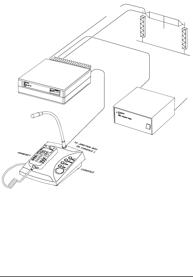
Figure 3: Typical fixed NGT AR or SR station
NOTE
The junction box is fitted inside the desk
console. The connectors on the junction box are
at the rear of the desk console.
BROADBAND ANTENNA
ANTENNA
ANTENNA CONTROL OPTIONAL
TUNER
AC POWER
POWER
SUPPLY
RF UNIT
Installation
NGT Transceiver Getting Started Guide 25
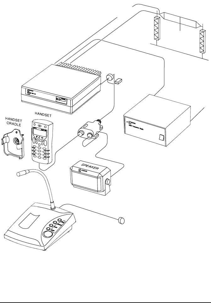
Figure 4: Typical fixed NGT AR Voice or VR station
BROADBAND ANTENNA
AC POWER
ANTENNA
ANTENNA CONTROL
POWER
SUPPLY
RF UNIT
4-WAY
CONNECTOR
10-WAY
CONNECTOR
OPTIONAL
CONSOLE
HANDSET & SPEAKER
CONNECTOR
OPTIONAL
TUNER
10-WAY
CONNECTOR
Installation
26 NGT Transceiver Getting Started Guide
Cables
NOTE
The Code 766 Desk Console comes with a 2 m
cable that connects directly to the 10-way
connector from the RF unit. The console
replaces the 6 m handset and speaker connector
cable, and external speaker. The handset
connects directly to the back of the console.
Table 3: Cables for a typical fixed NGT station
Cable Symbol Part number
CIB cable between RF unit and consolea (NGT
AR and SR Transceivers only)
a. The part number for this cable corresponds to a 6 m CIB cable. The cable is also available in a
number of shorter or longer lengths.
08-05610-006
Handset and speaker connector cable (NGT AR Voice
and VR Transceivers only)
08-06022-001
Coaxial cable between RF unit and antennab
b. The part number for this cable corresponds to a 30 m coaxial cable. The cable is also available
in a number of shorter lengths.
08-01503-030

Installation
NGT Transceiver Getting Started Guide 27
Mounting a fixed NGT station
A fixed NGT AR or SR station is most commonly mounted
using a desk console (Codan part number 15-10471). A fixed
NGT AR Voice or VR station may be mounted using a desk
console (Codan part number 15-00766). For general guidance
on suitable locations for equipment and installing the fixed
station see the reference material on the enclosed CD.
Desk console
The pre-assembled NGT Desk Console (Codan part number
15-10471, used with the NGT AR and SR Transceivers only)
combines a handset, a goose-neck microphone, a junction box,
an in-built speaker, and a headphone jack (see Figure 3 on
page 24). The Code 766 Desk Console (Codan part number
15-00766, used with the NGT AR Voice and VR Transceivers
only) does not have an internal junction box or attached
handset. The handset connects to the rear of the console. The
console cradles the handset.
RF unit and transceiver supply
The RF unit and the transceiver supply are self-contained and
are usually stacked loosely. If you want to mount the RF unit
and/or the transceiver supply, contact your Codan
representative to obtain a rack-mounting unit or the
appropriate mounting cradles.
WARNING If you are mounting an RF unit in a cradle, do
not fit rubber feet to the bottom of the RF unit.
NOTE
If you are transferring a mobile station to a fixed
station, and you are not mounting the RF unit in
a cradle, rubber feet can be fitted to the bottom
of the RF unit. The rubber feet are available
from Codan (Codan part number
30-11208-000).

Installation
28 NGT Transceiver Getting Started Guide
Rack-mounting unit
A rack-mounting unit consists of a 19 inch rack tray. It can be
used in conjunction with a desk console, or the handset and
cradle, to mount your fixed station.
Connecting a fixed NGT station
Connecting a fixed NGT AR or SR station
To connect a fixed NGT AR or SR station:
1Connect the socket at the end of the cable to the plug
at the end of the cable lead from the RF unit, then
secure the locking ring tightly into position.
1Connect the socket at the opposite end of the cable to
the plug at the rear of the desk console, then secure
the locking ring tightly into position.
1Connect the plug at the end of the cable to the socket at
the end of the cable lead from the RF unit, then secure
the locking ring tightly into position.
1Connect the plug at the opposite end of the cable to the
socket located at the base of the antenna, then secure the
locking ring tightly into position.
NOTE The handset is supplied connected to the desk
console (Codan part number 15-10471).

Installation
NGT Transceiver Getting Started Guide 29
Connecting a fixed NGT AR Voice or VR station
To connect a fixed NGT AR Voice or VR station:
1Connect the lead from the handset and speaker connector
or desk console to the 10-way plug on the cable lead
from the RF unit, then secure the locking ring tightly into
position.
1Connect the plug of the handset cable to the socket on
the handset and speaker connector or to the rear of the
optional Code 766 Desk Console, then secure the locking
ring tightly into position.
1Do one of the following:
• If you are using the handset and speaker connector and
cable, connect the plug at the end of the speaker cable
to the socket on the handset and speaker connector,
then secure the cable by pushing it into the slot on the
side of the connector (see Figure 4 on page 25).
• If you are using the optional Code 766 Desk Console,
connect the 2 m flying lead from the rear of the console
to the 10-way connector plug on the cable lead from
the RF unit, then secure the locking ring tightly into
position.
1Connect the plug at the end of the cable to the socket at
the end of the cable lead from the RF unit, then secure
the locking ring tightly into position.
1Connect the plug at the opposite end of the cable to the
socket located at the base of the antenna, then secure the
locking ring tightly into position.

Installation
30 NGT Transceiver Getting Started Guide
Connecting an automatic tuner to the RF unit and
antenna (optional)
To connect the tuner to the RF unit:
1Connect the plug at the end of the coaxial cable from the
tuner to the socket at the end of the cable lead from the
RF unit, then secure the locking ring tightly into position.
1Connect the plug at the end of the control cable from the
tuner to the socket at the end of the cable lead from the
RF unit, then secure the locking ring tightly into position.
1Connect the antenna to the antenna connector on the
tuner, then secure it tightly into position.
Connecting the transceiver supply
To connect the transceiver to the transceiver supply:
1Connect the DC output from the transceiver supply to the
plug at the end of the 12 V cable lead from the RF unit.
1Connect the transceiver supply to the AC mains supply.
Connecting ancillary equipment
The NGT AR and SR Transceiver mobile systems use the
junction box for connecting to ancillary equipment.
The 4-way connector on the RF unit of the NGT AR Voice
Transceiver is available for connecting a GPS receiver.
NOTE
You may need to install a tuner to improve the
efficiency of the antenna in your fixed station
(see the reference material on the enclosed CD).
NOTE
The tuner used in most applications has
connectors at the end of the cables attached to
the tuner, as described below. However, you
may have a tuner that has sockets on the
connector panel of the tuner.
NGT Transceiver Getting Started Guide 31
CODAN
3 The handset
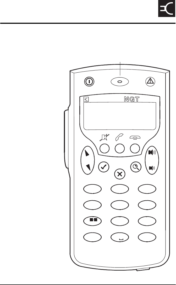
Figure 5: The handset
CLAR
2ABC
MODE
3DEF
6
MNO
HELP
5
JKL
4
GHI
7
PRS
SV
SEC
8
TUV
9WXY
CALL
#LOGS
VIEW
0
EASI
*TALK
TUNE
1
QZ
MUTE CALL SCAN
programming jack
PTT button
microphone
The handset
32 NGT Transceiver Getting Started Guide
The handset comprises:
•an LCD
• navigation keys ( , , , , )
• volume controls ( , )
•MUTE, CALL and SCAN hot keys
• alphanumeric keys (0–9, *, #)
• emergency key ( )
• power key ( )
• microphone
• PTT button
• programming jack
There are two ways to use the keys on the handset. You can:
•press a key, briefly
•hold a key for 2 seconds
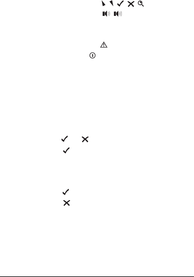
The and keys
Press to:
• select the item on the active line in the list
• save changes
• answer ‘yes’ to prompts
Hold to edit settings.
Press to:
• navigate up from settings to entries
• backspace over text
• remove messages on the screen
• cancel changes
• answer ‘no’ to prompts

The handset
NGT Transceiver Getting Started Guide 33
Hold to go from any location to the home screen. If you
have entered text into a setting and want to discard the
changes you made, hold .
The scroll keys
The and keys are the scroll keys. Use these keys to scroll
up or down through any list, to scroll left or right over text,
and to increase or decrease a value.

The handset
34 NGT Transceiver Getting Started Guide
Hot keys
Hot keys enable you to perform a task quickly. The transceiver
comes with some standard hot keys programmed; the keys are
labelled with the corresponding task performed. You can also
create your own hot keys (see the reference material on the
enclosed CD).
Table 4: Standard hot keys
Hot key Function
MUTE Pressing MUTE toggles mute on or off.
CALL Pressing CALL starts a call.
SCAN Pressing SCAN switches off scanning, or if you were in a call,
ends the call and switches scanning on.
TUNE Pressing TUNE displays the PTT to tune screen so you can
manually tune the antenna.
CLAR Pressing CLAR enables you to adjust the receive frequency to
compensate for any frequency offset between your transceiver
and the remote transceiver.
MODE Pressing MODE selects the next allowable mode programmed
for the channel, usually USB or LSB.
V/S Pressing V/S toggles the mute type between Voice mute and
Selcall mute.
SEC Pressing or holding SEC enters Secure mode, if the hardware
option is fitted, and special firmware is programmed into the
transceiver and enabled.
9 Pressing 9 displays your current GPS position, if the hardware
option is fitted and enabled.
EASITALK Pressing EASITALK toggles the DSP noise reduction algorithm
on or off.
The handset
NGT Transceiver Getting Started Guide 35
VIEW Pressing VIEW toggles between the channel screen and the
Address List.
CALL LOGS Pressing CALL LOGS repeatedly steps through a number of
call logs: Calls Out, Calls In, then back to the screen from which
you began. In these logs, you can view the details of the calls.
(Emergency)
Holding begins an automatic Emergency call transmission
using call information contained in the Emergency entries in the
Address List.
+ 9 Pressing + 9 enables you to change the default setting for the
screen contrast.
+ 0 Pressing + 0 enables you to change the default setting for the
screen and keypad backlighting.
Table 4: Standard hot keys (cont.)
Hot key Function
The handset
36 NGT Transceiver Getting Started Guide
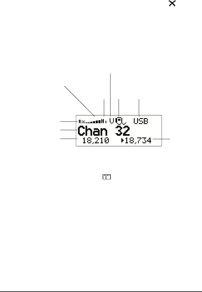
The channel screen
The channel screen is displayed when you press or VIEW.
Figure 6: The channel screen in the Channel List
When the transceiver is scanning, the call type icon is replaced
by the scanning icon and the channel information is
replaced by Scanning.
Tx power
indicator
(Hi/Lo)
channel name
call
Rx freq (kHz)
Rx/Tx indicator
mute type
indicator
signal
strength
(V/S,
type
icon
highlighted
when mute
is on)
mode
indicator
Tx freq (kHz)
(not shown if Tx/Rx
are the same)

NGT Transceiver Getting Started Guide 37
CODAN
4 Getting started
This section contains the following topics:
Switching on the transceiver (38)
Setting up basics (39)
Selecting a channel (40)
Making a basic voice call (41)
Making a Selective call (42)
Scanning channels (44)
WARNING
You should not transmit from your transceiver
or tune the antenna unless people are beyond the
safe working distance of:
• 1.5 m (5 ft) of any part of a mobile antenna
• 2 m (7 ft) of any part of a fixed antenna in a
data installation of up to 125 W output
• 5 m (17 ft) of any part of a fixed antenna in a
data installation of up to 1 kW output

Getting started
38 NGT Transceiver Getting Started Guide
Switching on the transceiver
To switch on the transceiver:
1Press .
If you are prompted to enter a password, enter your user
or administrator password, then press .
If you enter an incorrect password it is automatically
erased. If you enter an incorrect password three times,
the transceiver automatically switches off.
Switching off the transceiver
To switch off the transceiver:
1Hold .
The transceiver is switched off.

Getting started
NGT Transceiver Getting Started Guide 39
Setting up basics
NOTE
Basic information for the transceiver, such as
channels, self addresses, time and date, and
enabling channels for scanning, should be set up
by your system administrator using the NGT
System Programmer. If Quick Start is enabled
you can enter some of this information (see
page 51, Using Quick Start).

Getting started
40 NGT Transceiver Getting Started Guide
Selecting a channel
To select a channel:
1Press VIEW until the channel screen is displayed.
If scanning is on, press SCAN to switch it off.
1Scroll through the channels in the list. Stop scrolling
when the channel you want is displayed.
The channel is selected.
1If you want to change the sideband or IF filter settings,
press MODE.
If the mode does not change, there is only one mode for
the channel.
NOTE
If you have an automatic antenna fitted,
press PTT to tune the antenna to the
currently selected channel.

Getting started
NGT Transceiver Getting Started Guide 41
Making a basic voice call
To make a basic voice call:
1Select the channel that you want to use (see page 40,
Selecting a channel).
1Hold down PTT then speak, releasing PTT when you
have finished speaking.
Muting the transceiver
If you do not want to listen to on-air noise, you can mute the
transceiver so that you will only hear voice traffic on the
channel.
To switch mute on or off:
1Press MUTE.
When the channel screen is displayed, the mute status is
indicated by a V (Voice) or S (Selcall) at the top centre of
the screen. If the letter is highlighted, mute is on.
If the letter is not highlighted, mute is off.
1Press V/S until V is displayed on the channel screen.
The transceiver will remain muted until it detects voice
traffic on the channel.
Getting started
42 NGT Transceiver Getting Started Guide
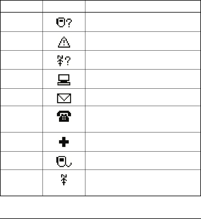
Making a Selective call
To make a Selective call:
1Press CALL.
1Enter the address of the station you want to call, scroll to
the type of call you want to make, then press CALL.
NOTE The call types available will depend on the
options installed in your transceiver.
Call type Icon Used for...
Channel Test Testing the audible quality of a channel in a
Codan Selcall or Open Selcall network.
Emergency Sending an emergency alert tone with a call.
Get Position Requesting the location of a remote transceiver
with a GPS receiver connected and enabled.
Get Status Requesting diagnostic or configuration
information from a remote transceiver.
Message Sending a message to a remote transceiver.
Phone Sending a call to a radio/telephone
interconnect unit, which connects the call to
the public telephone network.
RFDS Emgcy Sending an emergency call to an RFDS base
station (Australia only).
Selective Sending a selective call to a remote transceiver.
Send Position Sending your GPS position to a remote
transceiver. A GPS receiver must be connected
to and enabled in your transceiver.

Getting started
NGT Transceiver Getting Started Guide 43
1If you are prompted for details about the call, use the
information in the following table to enter them, then
press CALL.
1If you made the call in:
• an ALE/CALM network, wait until a message informs
you that the call has been successful (this means your
call has been automatically answered by the other
station)
• a Codan Selcall or Open Selcall network, wait until a
message informs you that the call has been sent and
listen for audible beeps transmitted from the other
station
1Hold down PTT then speak.
Release PTT when you have finished speaking.
1To end the call, press SCAN.
If the transceiver was scanning prior to the call it
resumes scanning.
If this prompt is
displayed...
Do this...
Select network • select the network in which you want to make the call
My address? • select or enter the self address from which you want to send
the call
Select chan/mode In an ALE/CALM network:
• select <auto> if you want the transceiver to select the best
channel/mode for the call, starting with the channel on
which the most recent successful link was established, or
• select the channel/mode you want to use to make the call
In a Codan Selcall or Open Selcall network:
• select the channel/mode you want to use to make the call
and check that it is clear of voice and data traffic
NOTE To abort the call before a connection to the
other station is made, press PTT.

Getting started
44 NGT Transceiver Getting Started Guide
Scanning channels
Before you can switch scanning on, you need to allocate some
channels to be scanned. If you have Quick Start enabled, you
can create a scan list from channels programmed into the
transceiver (see page 51, Using Quick Start). If this feature is
disabled, your system administrator will allocate some
channels to a network, then enable scanning of this network.
Switching scanning on or off
To switch scanning on or off:
1Press SCAN.
Scanning is toggled on or off.
When scanning is switched on, mute is also switched on.
You cannot use PTT while the transceiver is scanning.
NOTE
SCAN is also used to end a call.
If the transceiver was scanning before the
call was sent or received, it resumes
scanning. If the transceiver was not
scanning before the call, press SCAN to
switch scanning on.

Getting started
NGT Transceiver Getting Started Guide 45
Pausing scanning
To pause scanning:
1Do one of the following:
• to pause scanning on the current channel/mode,
press
• to pause scanning and scroll to another channel/mode,
press or
The channel/modes through which you can scroll are
those in the networks that were being scanned. They are
not listed alphabetically but in the order in which they
were being scanned.
If you do not press a key within 30 seconds, the
transceiver automatically resumes scanning.
1While scanning is paused, do one or more of the
following:
• to converse, hold down PTT
• to resume scanning immediately, press

Getting started
46 NGT Transceiver Getting Started Guide
This page has been left blank intentionally.
NGT Transceiver Getting Started Guide 47
CODAN
Appendix A—Entering and
editing text
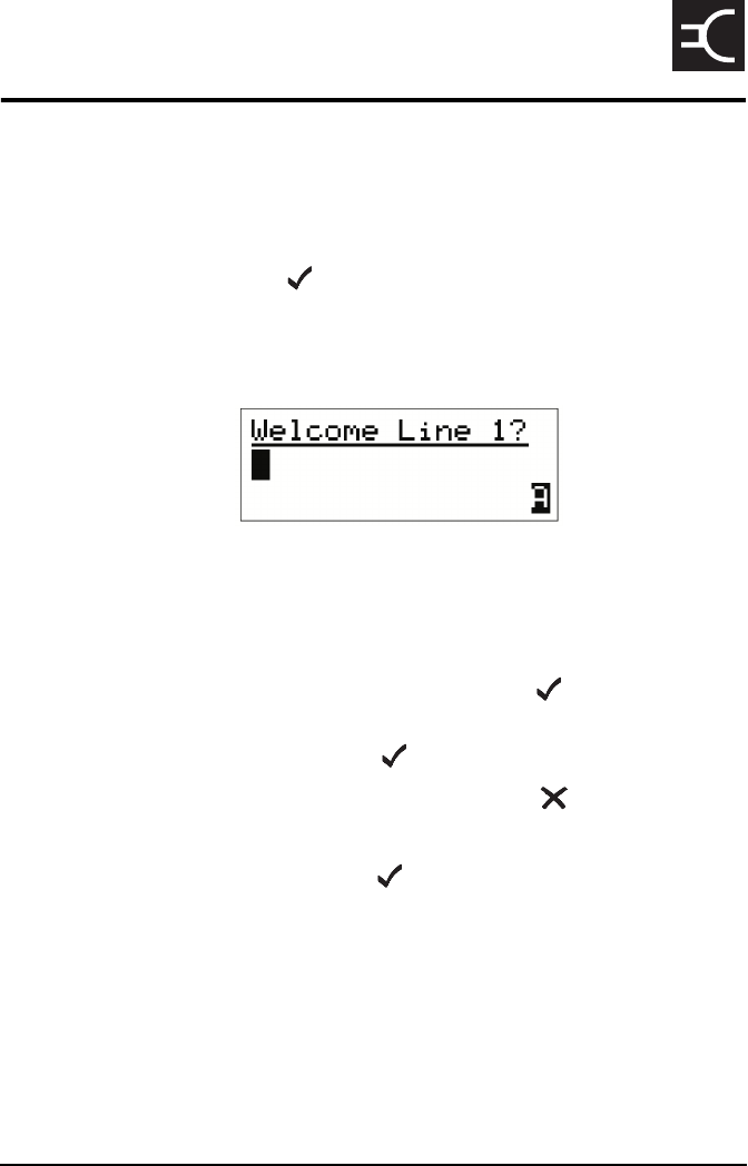
Editing a screen
To gain access to an editable screen:
1Hold .
A question mark is displayed at the end of the heading to
show that you can now enter and/or edit text in the
setting.
1Do one of the following:
• To use the text displayed, press .
• To enter new text, start typing. When you have entered
the text, press .
• To edit the text displayed, press . The cursor is
placed at the end of the line so you can backspace over
characters and/or enter new text. When the text is
correct, press .
NOTE If text has already been entered on the line
it is highlighted.
Entering and editing text
48 NGT Transceiver Getting Started Guide
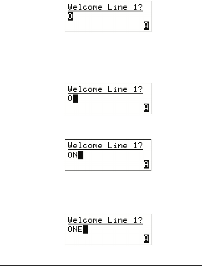
Entering text
To enter text in an editable screen:
1To enter one of the letters on a key, press the key
repeatedly until the letter is displayed.
1To enter another letter on the same key, wait until the
cursor moves to the next space...
...then press the key repeatedly until the letter you want is
displayed.
1To enter a letter on another key, press the key for the
letter.
You do not need to wait until the cursor moves to the
next space.
NOTE You can also hold the key until the letter
you want is displayed, then release the key.
Entering and editing text
NGT Transceiver Getting Started Guide 49
Changing between alpha and numerical characters
To change between upper-case and lower-case letters and
numbers in an editable screen:
1Press # to change the character/case indicator at the
bottom right of the screen from A (upper-case) to a
(lower-case) to # (numbers).
Moving the cursor
To move the cursor across the text:
1Use or to move the cursor left or right respectively.
Inserting text
To insert text:
1Use or to move the cursor to the point where you
want to insert text (or a space), then press the required
character key.
NOTE
When you are prompted to enter a call
address, the characters that you can enter
are determined by the call systems installed
in the transceiver.
NOTE
If you want to insert a space, make sure
that A or a is displayed at the bottom right
of the screen before you press 0 otherwise
you will enter a zero.
NOTE You can enter a special character using *,
or with and .

Entering and editing text
50 NGT Transceiver Getting Started Guide
Deleting text
To delete text:
1Use or to move the cursor one position to the right
of the character that you want to delete, then press .
Saving text changes
To save the changes you have made:
1Press .
The question mark is removed from the heading.
If you do not want to save the text, hold to discard the
changes.
NGT Transceiver Getting Started Guide 51
CODAN
Appendix B—Using Quick Start
Quick Start provides simple methods to configure your
transceiver to a basic operating state.
Quick Start will be available if your transceiver contains only
one station self address and network names from this default
list:
•*Voice
• *Selcall
•*CALM
•!Default
Opening and closing Quick Start
To open Quick Start:
1Hold .
To close Quick Start:
1Press or hold .
NOTE
When you hold , you should see the Quick
Start entries, for example, Add/Edit channel,
Set scan list etc. If these entries are not
displayed, then Quick Start is not available to
you.
Quick Start is only available in countries that
permit programming of transmit frequencies
using the handset.
For detailed information on programming your
transceiver without Quick Start see the
reference material on the enclosed CD.

Using Quick Start
52 NGT Transceiver Getting Started Guide
Adding/Editing a channel
To add or edit a channel:
1Open Quick Start.
1Scroll to Add/Edit channel, then press .
1Enter the name of the channel that you want to use, then
press .
If you want to use an existing channel, scroll to the
channel, then press .
1Enter the receive frequency in kilohertz, then press .
1Enter the transmit frequency in kilohertz, then press .
1Scroll to the mode combination you want to use, then
press .
The transceiver returns to Quick Start.
1If you want to add more channels to your transceiver,
scroll to Add/Edit channel and repeat this process.
1Close Quick Start, if required.
NOTE For help with entering text see page 47,
Entering and editing text.
NOTE
You can enter the frequency to three
decimal places. Press * to enter a decimal
point, then continue with entering the
frequency.
NOTE
If you want to make or receive calls on this
new channel, you must add it to your scan
list.

Using Quick Start
NGT Transceiver Getting Started Guide 53
Setting up a scan list
To set up a scan list:
1Open Quick Start.
1Scroll to Set scan list, then press .
The first channel in the transceiver is displayed.
1If you want to add this channel to the scan list, press .
If you do not want to add this channel to the scan list,
press .
When all the channels have been viewed or you have
added 15 channels to your scan list, the transceiver
returns to Quick Start.
If you do not want to scroll through all the channels in
your scan list, hold to return to Quick Start.
1Close Quick Start, if required.
CAUTION
Each time you enter Set scan list, the
resulting scan list overwrites the existing
scan list.

Using Quick Start
54 NGT Transceiver Getting Started Guide
Setting the time and date
To set the time and date:
1Open Quick Start.
1Scroll to Set time/date, then press .
The display appears with a line under the day of the
month.
1Use or to change the current setting to the correct
value, then press .
The line appears under the month.
1Repeat the previous step until you have made all of the
changes to the time and date.
When all the changes have been made, the transceiver
returns to Quick Start.
1Close Quick Start, if required.

Using Quick Start
NGT Transceiver Getting Started Guide 55
Setting your station self address
To set your station self address:
1Open Quick Start.
1Scroll to Set my address, then press .
1Enter your station self address (maximum of 6 numeric
digits for Codan Selcall or Open Selcall networks, or
15 upper-case/numeric digits for ALE/CALM networks),
then press .
1Close Quick Start, if required.
NOTE
When Quick Start is available, any self address
that you enter using this method replaces the
previous self address. If you want to enter more
than one self address, and hence disable the
Quick Start features, see the reference material
on the enclosed CD.
NOTE For help with entering text see page 47,
Entering and editing text.

Using Quick Start
56 NGT Transceiver Getting Started Guide
Adding/Editing an entry in the Address List or Call
Book
To add or edit an address that you call frequently:
1Open Quick Start.
1Scroll to Address/CallBk, then press .
1Enter the name of the station or person that you want to
add to the list, or use or to select an existing entry,
then press .
1Scroll to the type of call that you want to make, enter the
station address that you want to call, then press .
1If you selected Message? or No call type, enter the
message, then press .
If you do not want to select a message, press .
1Scroll to the call system that you want to use to make the
call, then press .
1If you selected Phone? or No call type, select
<blank> for the phone link that you want to use, then
press .
When all the changes have been made to the call address,
the transceiver returns to Quick Start.
1If you want to add more call addresses to your Address
List or Call Book, scroll to Address/CallBk and repeat
this process.
1Close Quick Start, if required.
NOTE For help with entering text see page 47,
Entering and editing text.

Using Quick Start
NGT Transceiver Getting Started Guide 57
Deleting an entry
To delete addresses, channels or phone links:
1Open Quick Start.
1Scroll to Delete..., then press .
1Scroll to the list from which you want to delete an item,
then press .
1Scroll to the item you want to delete, then press .
1Close Quick Start, if required.
NOTE
If you delete a channel from the Channel
List, it is deleted automatically from the
scan list.

Using Quick Start
58 NGT Transceiver Getting Started Guide
This page has been left blank intentionally.
NGT Transceiver Getting Started Guide 59
CODAN
Appendix C—Using a GPS
receiver
The GPS option is available for NGT AR, SR, and AR Voice
Transceivers. If you have this option enabled and a GPS
receiver connected, you can view the distance and bearing to
other transceivers from which you have received a position.
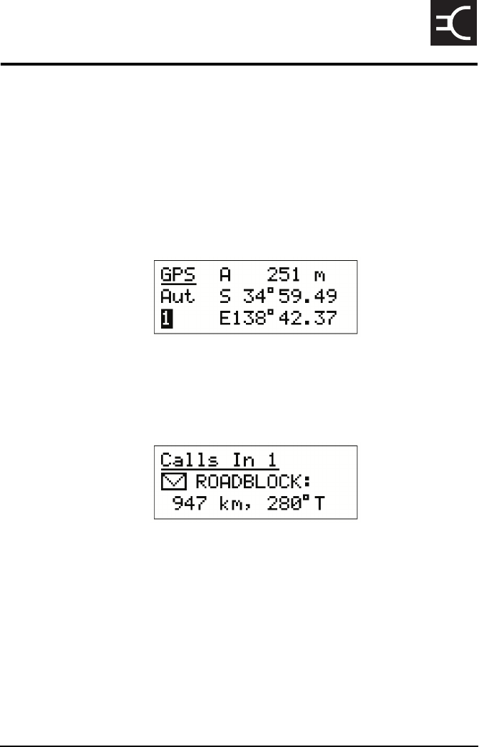
To access GPS information:
1Press 9 to see the GPS screen.
To view distance and bearing to another transceiver:
1Go to an Address List or Call Log entry containing a
GPS position of the other station.
The transceiver calculates the distance to the other
transceiver and its bearing from true north with respect to
your current location.

Using a GPS receiver
60 NGT Transceiver Getting Started Guide
This page has been left blank intentionally.

NGT Transceiver Getting Started Guide 61
CODAN
Appendix D—Transceiver
specifications
Table 5: NGT Transceiver specifications
Item Specification
Frequency range Transmit: 1.6 to 30 MHz
Receive: 250 kHz to 30 MHz
Channel capacity NGT AR, SR, AR Voice: 400 channels
NGT VR: 20 channels
Operating modes Single sideband (J3E) USB and LSB or switched USB/LSB,
AM H3E (optional)
Sensitivity Frequency:
0.25 to 30 MHz
RF amp off:
1.25 µV PD, –105 dBm
Frequency:
1.6 to 30 MHz
RF amp on:
0.12 µV PD, –125 dBm
For 10 dB SINAD with greater than 50 mW audio output
Transmitted
power
NGT SR, VR:125W PEP
NGT AR, AR Voice:100W PEP
Environment Ambient temperature: –30 to 60°C
Relative humidity: 95% non-condensing
Derate upper ambient temperature by 1°C per 330 m (360 yd)
above sea level

Transceiver specifications
62 NGT Transceiver Getting Started Guide
Size, weight and
sealing
2010/2011 RF Unit (excluding vehicle mounting frame)
Size: 210 mm W × 270 mm D × 65 mm H
(8.4 in W × 10.8 in D × 2.6 in H)
Weight: 3.3 kg (7.3 lb)
Sealing: IP52
2020 Handset
Size: 65 mm W × 35 mm D × 130 mm H
(2.6inW × 1.4inD × 5.2inH)
Weight: 0.3 kg (0.7 lb)
Sealing: IP41
2030 Junction Box (NGT AR and SR Transceivers only)
Size: 135 mm W × 106 mm D × 38 mm H
(5.4inW × 4.3inD × 1.5inH)
Weight: 0.4 kg (0.9 lb)
Sealing: IP41
Handset and speaker connector (NGT AR Voice and VR
Transceivers only)
Size: 42 mm W × 55 mm D × 22 mm H
(1.7inW × 2.2inD × 0.9inH)
Sealing: IP41
Table 5: NGT Transceiver specifications
Item Specification

NGT Transceiver Getting Started Guide 63
CODAN
Appendix E—HF radio
transmission
The HF band is the range of frequencies between 3 and
30 MHz. HF transceivers usually cover a frequency range of
1.6 to 30 MHz.
Codan HF transceivers transmit on single sidebands. This
reduces the power required to send HF signals and increases
the number of channels available within the HF spectrum.
HF transceivers are primarily used for long-range
communication where distances of 3000 km (1800 mi) and
more are possible. Obstructions such as buildings and
mountains have little effect on long-range communication. HF
radio can cover such large distances because of the way the
transmitted radio signal propagates.
HF radio waves propagate in three ways simultaneously:
• ground wave
• direct wave
• sky wave
Ground wave
The ground wave travels near the ground for short distances,
typically up to 100 km (60 mi) over land and 300 km (190 mi)
over sea. The distance covered depends upon the operating
frequency, transmission power, and type of terrain.
Direct wave
The direct wave travels in a direct line-of-sight from the
transmitter to the receiver.
HF radio transmission
64 NGT Transceiver Getting Started Guide
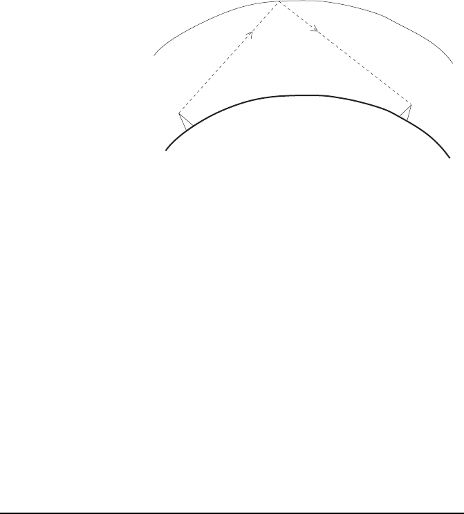
Sky wave
The sky wave is the most important form of HF propagation.
The radio wave is transmitted toward the sky and is reflected
by the ionosphere to a distant receiver on earth.
The reflective properties of the ionosphere change throughout
the day, from season to season, and yearly.
Figure 7: The reflective properties of the ionosphere
Frequency, distance and time of day
The extent to which a radio wave is reflected depends on the
frequency that is used. If the frequency is too low, the signal is
absorbed by the ionosphere. If the frequency is too high, the
signal passes straight through the ionosphere. Within the HF
band, low frequencies are generally considered to be in the
range of 2 to 10 MHz. High frequencies are above 10 MHz.
A frequency chosen for daytime transmission may not
necessarily be suitable for night-time use. During the day, the
layers of the ionosphere are thick. The layers absorb lower
frequencies and reflect higher frequencies. At night, the
ionosphere becomes very thin. The low frequencies that were
absorbed during the day are reflected, and the high frequencies
that were reflected during the day pass straight through.
Summer HF communications usually operate on higher
frequencies than those used in winter over the same distance.
ionosphere
transmitter receiver
emitted
HF wave
reflected
HF wave

HF radio transmission
NGT Transceiver Getting Started Guide 65
Solar activity varies over an 11 year cycle. Higher frequencies
need to be used during periods of peak activity.
It is important to remember that you may need to change the
frequency you are using to achieve the best communication.
The general rules of thumb for HF communication are:
• the higher the sun, the higher the frequency
• the further the distance, the higher the frequency
Channels and modes
A channel is a name that is given to a frequency or a pair of
frequencies, e.g. ‘Channel 1’, ‘4500’ and ‘Headquarters’. The
frequencies may be any frequencies within the HF range.
Each channel has one or more modes associated with it. Each
mode indicates a sideband that can be used with the channel,
such as USB or LSB. When you make a call you need to
specify the channel and the mode you want to use.
Table 6 shows examples of channels and the information
associated with them.
Table 6: Examples of channels and modes
Channel Receive frequency
(kHz)
Transmit frequency
(kHz)
Modes
Channel 1 10600 10600 LSB, USB
4500 4500 – AM
Headquarters 22758 23000 USB

HF radio transmission
66 NGT Transceiver Getting Started Guide
Networks and scanning
A network is two or more stations that use the same
frequencies and call system to communicate. The frequencies
are allocated by a government authority and enable the
network to maintain HF communication throughout the day
and night.
The call system is the method the network uses to make and
receive calls. For example, in networks that use the Codan
Selcall or Open Selcall call system to make calls, the user
enters the address of the station they want to call, then selects
the channel/mode on which to make the call. In networks that
use the ALE/CALM call system, the transceiver selects the
best channel/mode for the call.
The transceiver can be set to scan the channel/modes used by
your network to detect incoming calls. It is recommended that
when you are not using the transceiver to communicate you
switch scanning on. This ensures that you can receive calls
from stations in your network.
Etiquette for the use of HF radio
There is a standard procedure for communicating over HF
radio. Before you begin transmitting, switch off scanning,
select a channel, then press PTT on the handset to initiate
tuning of the antenna. Listen to the channel that you are going
to use and ensure that there is no voice or data communication
taking place. You may need to wait until the channel is clear or
select another channel.
When you first establish communication with another station
it is customary to state their call sign and then your own using
the phonetic alphabet (see Table 7 on page 67). For example:
‘Alpha Bravo One, this is Alpha Bravo Two. Do you receive
me? Over.’

HF radio transmission
NGT Transceiver Getting Started Guide 67
In this example your call sign is AB2 and you are calling a
station with the call sign AB1. A call sign is a group of letters
and numbers issued by a government authority to identify a
station. The phonetic alphabet is used to ensure that your call
sign is understood.
The word ‘over’ is used to signify the end of your
transmission. The transceiver may be set up to transmit a short
beep when you release the PTT button on the handset. When
your conversation with the other party is finished, the party
that speaks last should say ‘out’.
Swearing or foul language should not be used—heavy
penalties can apply.
Keep communication as short as possible.
Table 7: The phonetic alphabet
Letter Word Letter Word
A Alpha N November
B Bravo O Oscar
C Charlie P Papa
DDeltaQQuebec
EEchoRRomeo
F Foxtrot S Sierra
GGolfTTango
HHotelUUniform
I India V Victor
J Juliet W Whiskey
KKiloXX-ray
L Lima Y Yankee
M Mike Z Zulu

HF radio transmission
68 NGT Transceiver Getting Started Guide
This page has been left blank intentionally.

NGT Transceiver Getting Started Guide 69
CODAN
Appendix F—Definitions
Standards and icons
The following standards and icons are used in this guide:
This typeface Means...
Italic a cross-reference or text requiring emphasis
Bold a menu option in the transceiver
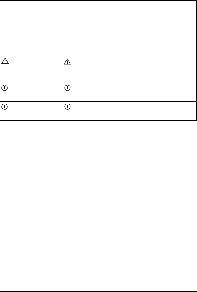
This icon Means...
! a step within a task
NOTE the text provided next to this icon may be of
interest to you
CAUTION proceed with caution as your actions may
lead to loss of data, privacy or signal quality
WARNING your actions may cause harm to yourself or
the equipment

Definitions
70 NGT Transceiver Getting Started Guide
Acronyms and abbreviations
This term Means...
ALE automatic link establishment
AM amplitude modulation
BER bit error rate
CALM Codan automated link management
CW carrier wave
DC direct current
DSP digital signal processor
ETSI European Telecommunications Standards
Institute
FCC Federal Communications Commission
GPIO general purpose input/output
GPS global positioning system
HF high frequency
ICNIRP International Commission on Non-Ionizing
Radiation Protection
ID identification
IF intermediate frequency
LBT listen before transmit
LCD liquid crystal display
LED light emitting diode
LQA link quality analysis
LSB lower sideband
NSP NGT system programmer

Definitions
NGT Transceiver Getting Started Guide 71
PA power amplifier
PC personal computer
PTT press-to-talk
R&TTE radio and telecommunications terminal
equipment
RF radio frequency
RFDS Royal Flying Doctor Service
Rx receive
SB sideband
SINAD (signal + noise + distortion)-to-(noise +
distortion) ratio
tcvr transceiver
Tx transmit
USB upper sideband
V firmware/software version
This term Means...

Definitions
72 NGT Transceiver Getting Started Guide
Glossary
This term Means...
active line The line below the title of a list on the
handset screen. Items in the active line are
selected by pressing .
address The HF transceiver equivalent of a
telephone number. Your station self address
is used by other stations to call you, and it is
sent when you make calls to identify you as
the caller. It is sometimes referred to as an
ID, a station ID, or a self ID.
automatic tuning
antenna
An antenna designed for use with
multichannel transceivers. It uses a
microcontrolled stepper motor to give
continuous tuning over the operating
frequency range of the antenna.
call detect time The length of time during scanning that the
transceiver pauses on each channel in order
to detect an incoming call. It is the inverse
of the scan rate.
channel Frequencies programmed in the transceiver
to transmit and receive signals on air.
Channel Test
call
A call that enables you to test the quality of
a channel in a Codan Selcall or Open Selcall
network.
control cable A cable connecting two items of equipment
that allows control information to be passed
between the equipment.
Emergency call A call that enables you to trigger an
emergency alarm at a specific station then
speak to an operator there.

Definitions
NGT Transceiver Getting Started Guide 73
fixed base
station
A transceiver that is permanently installed
and cannot be moved without significant
effort. It consists of a transceiver, a
transceiver supply, an antenna, control and
accessory devices, ancillary equipment, and
appropriate connecting cables.
frequency The number of cycles per second of a radio
wave, usually expressed in kilohertz.
Get Position call A call that gets the GPS position of a
specific station.
Get Status call A call that gets diagnostic or configuration
information about the transceiver at a
specific station.
handset A hand-held device that is used to control
the functions of a transceiver. It consists of a
microphone, PTT button, display and
keypad.
hot key A key on the handset or desk console that is
pre-programmed with a macro that enables
you to perform a task quickly.
junction box The unit in a transceiver to which a handset,
RF unit, speaker and related devices are
connected. The junction box receives the
instructions that a user enters through the
handset and sends these instructions to the
relevant devices. In an NGT AR Voice or VR
Transceiver, the junction box is not
required; the handset and speaker connect
directly to the handset and speaker
connector. In this case, all instructions are
processed by the RF unit.
This term Means...

Definitions
74 NGT Transceiver Getting Started Guide
listen before
transmit
If enabled, the automatic process that the
transceiver uses to detect whether or not
there is traffic on a channel and, when
necessary, select another channel or inform
the user that the channel is busy.
macro A short set of instructions to automate a task
you perform with the transceiver. When a
macro is assigned to a key, the key becomes
a hot key.
Message call A call that enables you to send a message to
a specific station.
mobile station A station that is usually mounted in a
vehicle or is portable and easily
transportable. It consists of a transceiver, a
power supply, an antenna, control and
accessory devices, ancillary equipment, and
appropriate connecting cables.
mode A type of reception or transmission you can
use with a channel, comprising a sideband
and an IF filter.
network Two or more stations that use the same
frequencies and call system to
communicate.
Phone call A call that enables you to connect to a
public telephone network.
PTT button Press-to-talk button, located on the left side
of the handset. This button enables you to
communicate during voice calls, switch
mute off, cancel voice calls prior to the
point where voice can be transmitted, cancel
calls where data is being transmitted, and
exit out of editable screens without saving
changes.
This term Means...

Definitions
NGT Transceiver Getting Started Guide 75
revertive A signal sent by a station in response to a
call.
RFDS Emgcy
call
A call that enables you to contact the RFDS
(NGT AR and AR Voice Transceivers only).
RF unit The device in a transceiver that modulates
audio signals onto radio frequencies that
can be transmitted on air, and that
demodulates the radio frequencies it
receives into audio signals.
Selective call A call that enables you to contact a specific
station, then speak to an operator.
Send Position
call
A call that sends your GPS position to a
specific station.
sideband A band of frequencies that is above or
below a modulated carrier frequency.
station A point of communication consisting of a
transceiver, a power supply, an antenna,
ancillary equipment, and appropriate
connecting cables.
transceiver An RF unit, handset, speaker, and
appropriate connecting cables. The NGT AR
and SR Transceivers also include a junction
box.
This term Means...

Definitions
76 NGT Transceiver Getting Started Guide
Units
Unit multipliers
NOTE Imperial dimensions are in United States
Customary Units.
Measurement Unit Abbreviation
Length metre
(inch/feet/yard/
mile)
m
(in/ft/yd/mi)
Frequency hertz Hz
Time second s
hour h
Voltage volt V
Weight gram
(pound)
g
(lb)
NOTE
Units are expressed in accordance with ISO
1000:1992 ‘SI units and recommendations for
the use of their multiples and of certain other
units’.
Unit Name Multiplier
Mmega1000000
kkilo1000
m milli 0.001

Definitions
NGT Transceiver Getting Started Guide 77
About this issue
This is the sixth issue of the NGT Transceiver Getting Started
Guide. This guide describes V4.3 firmware, which includes
the distance and bearing capability with the GPS option, and
the Open Selcall call system.
The NGT VR Mobile Transceiver (with RF Unit 2011 and no
junction box) is now called the NGT VR Transceiver. The
previous NGT VR Transceiver (with RF Unit 2010 and
Junction Box 2030) is no longer available.
Associated documents
This guide is one of a series of documents associated with the
NGT Transceiver. The other documents are:
• NGT Transceiver Reference Manual (Codan part number
15-04126-EN) supplied on the CD inside the back cover
of this guide
• NGT Transceiver System Technical Service Manual
(Codan part number 15-02063-EN)
• Declaration of Conformity for the NGT AR Transceiver
(Codan part number 19-40130)
• Declaration of Conformity for the NGT SR Transceiver
(Codan part number 19-40121)
• Declaration of Conformity for the NGT AR Voice
Transceiver (Codan part number 19-40123)
• Declaration of Conformity for the NGT VR Transceiver
(Codan part number 19-40122)
• Declaration of Conformity for the 3020 Transceiver
Supply (Codan part number 19-40127)

Definitions
78 NGT Transceiver Getting Started Guide
This page has been left blank intentionally.

NGT Transceiver Getting Started Guide Index-1
CODAN
Index
A
Address List
adding/editing entries 56
calling from 42
ancillary equipment 22, 30
B
bearing 59
C
cables
fixed station 26
mobile station 17
call sign 66
call systems
ALE/CALM 66
Codan Selcall 66
Open Selcall 66
calls
from Address List 42
channel screen 36
channels
definition 65
manual selection 40
compliance
electromagnetic compatibility and safety
notices 7
earth symbols 10
electrical safety 9
electromagnetic compatibility 8
FCC 11
R&TTE Directive 5
declaration of conformity 5
product marking and labelling 5
protection of the radio spectrum 6
D
deleting entries 57
direct wave 63
distance 59
E
electromagnetic compatibility and safety notices
compliance
earth symbols 10
electrical safety 9
electromagnetic compatibility 8
entering and editing text
changing between alpha and numerical
characters 49
deleting text 50
editing a screen 47
entering special characters 49
entering text 48
inserting text 49
moving the cursor 49
saving text changes 50
F
FCC compliance 11
fixed station 23
cables 26
installing 28
mounting 27
19 inch rack-mounting unit 28
desk console 27
mounting cradles 27
frequency selection
depending on distance and time of day 64
G
GPS 59
ground wave 63
H
handset keys 31
HF radio transmission 63
I
installation 13
fixed 23
mobile 14

Index
Index-2 NGT Transceiver Getting Started Guide
M
mobile station 14
cables 17
installing 20
mounting 17
handset and speaker connector 18
handset cradle 17
junction box 18
RF unit 19
speaker 18
modes 40, 65
N
networks 66
NGT fixed station 23
NGT mobile station 14
P
password
entering 38
phonetic alphabet 67
power on/off 38
Q
Quick Start 51
adding/editing a channel 52
adding/editing an entry in the Address List or
Call Book 56
deleting an entry 57
opening and closing 51
setting the time and date 54
setting up a scan list 53
setting your station self address 55
R
R&TTE Directive
compliance 5
declaration of conformity 5
product marking and labelling 5
protection of the radio spectrum 6
S
safety
radiation 7
scan rate, see call detect time 72
scanning channels 44, 66
pausing channel scanning 45
selecting
an item in a list 32
channel 40
sky wave 64
station
fixed 23
installing 28
mounting 27
mobile 14
installing 20
mounting 17
W
wave
direct 63
ground 63
sky 64

www.codan.com.au
Head Office
Codan Limited
ABN 77 007 590 605
81 Graves Street
Newton SA 5074
AUSTRALIA
Telephone +61 8 8305 0311
Facsimile +61 8 8305 0411
asiasales@codan.com.au
Codan (UK) Ltd
Gostrey House
Union Road
Farnham Surrey GU9 7PT
UNITED KINGDOM
Telephone +44 1252 717 272
Facsimile +44 1252 717 337
uksales@codan.com.au
Codan US, Inc.
8430 Kao Circle
Manassas VA 20110
USA
Telephone +1 703 361 2721
Facsimile +1 703 361 3812
ussales@codan.com.au