Code Systems PAN06 Car Alarm Receiver User Manual
Code Systems Inc Car Alarm Receiver
User Manual
OCT/02/2002
CA-120 1
MODEL CA-120
REMOTE CONTROL AUTO ALARM SYSTEM
INSTALLATION & OPERATION INSTRUCTIONS
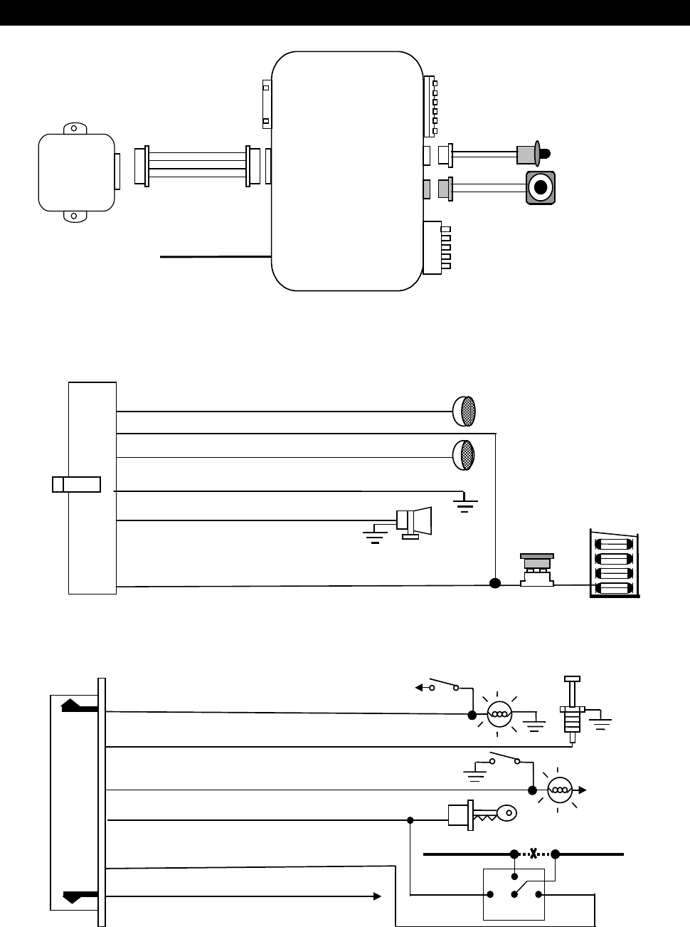
WIRING DIAGRAM
H1: Main 6 Pin White harness
H7: 6 Pin White Mini Connector
Black Antenna Wire
LED Indicator
Valet Switch
H6 4 Pin
Orange
H3 2 Pin
Blue
H2 2 Pin
White
H5 Black
Wire
Dual Zone
Shock
Sensor
H4: 6 Pin Door Lock/Unlock
Wire harness
H1 6 Pin
White
H4 6 Pin
White
H7 6 Pin
White
H1: MAIN 6 PIN WHITE WIRE HARNESS:
6. Red Wire: +12V To Constant Batter
y
Source
5. Brown Wire: Positive output To
4. Black Wire: Ground to Vehicle FRAME
1. White Wire: Turn Indicator Relay Output
2. Red / White Wire: Turn Indicator Relay Power input
Siren Or Horn (Programmable)
3. White Wire: Turn Indicator Relay Output
Turn Indicator
15A Fuse
H7: 6 PIN WHITE MINI CONNECTOR WIRE HARNESS:
6. Gray Wire: (-) 200mA Programmable Output
2. Blue Wire: Zone 2 / Instant Trigger Ground Input
1. Violet Wire: Zone 3 / Positive Door Pin Switch Input
4. Yellow Wire: Zone 5 / To I
g
nition Switched + 12V
5. Orange Wire: 200mA Grounded when armed
3. Green Wire: Zone 3 / Negative Door Pin Switch Input
85 86
30
87a
Cut To start solenoid
From ignition switch
Red wire White wire
Orange
wire
Channel 3 / 2 Step Door Unlock / Pager Output.
12V
12V
Yellow wire

OCT/02/2002
CA-120 2
WIRING
Keep wiring away from moving engine parts, exhaust pipes and high-tension cable. Tape wires that pass
through holes on the firewall to prevent fraying. Watches out sharp edges that may damage wires and
causes short circuit.
CAUTION: Do not connect the wire harness to the control module until all wiring to vehicle is complete.
H1: MAIN 6 PIN WIRE HARNESS :
H1/1 & 3. White wire – Turn Indicator Relay Output (5A Output for each) –
The WHITE wires transfer the power taken from the RED/WHITE wire to turn indicators, through the alarm
internal relay. Connect one of the two WHITE wires to right line of turn indicator and connect the other one
to the left line indicator.
H1/2. Red / White wire – Turn Indicator Power Input –
The RED/WHITE wire is the input to the flashing turn indicator relay. The connection of the RED/WHITE
wire will determine the output polarity of the flashing turn indicator relay.
If the vehicle you are working on has +12volt switched turn indicators, you don’t need connect this wire.
This wire already connected to +12volt.
If the vehicle’s turn indicators are ground switched, cut the RED/WHITE wire, connect the RED/WHITE to
chassis ground.
H1/4. Black wire –- System Ground –
This is main ground connection of the alarm module. Make this connection to a solid section of the vehicle
frame. Do not connect this wire to any existing ground wires supplied by the factory wire loom, make the
connection to the vehicle's frame directly.
H1/5. Brown wire – Siren Drive or Horn Output – (Set Feature III – 1 Programming)
SIREN DRIVE OUTPUT (Factory default setting)
This is the positive (+) output connection for the siren. Current capacity is 2 Amp. Make connection to
the (+) red wire from the siren. Make the (-) black wire coming from the siren to a good chassis ground.
(+) Low Current HORN OUTPUT -- (Set Feature III – 1 To Horn Output)
This wire is provided to use the existing vehicle's horn as the alarm system's optional warning audible
device. It's a transistorized low current output, and should only be connected to the low current positive
(+) output from the vehicle's horn switch.
H1/6. Red wire – System Power (+12V Constant) –
The RED wire supplies power to the system. Connect this wire to a constant +12 volt source.
H6: 4 PIN ORANGE CONNECTOR FOR 2 STAGE SHOCK SENSOR :
4. Green Wire / Warn Away Input
3. Blue Wire / Zone 4 Ground Trigger
2. Black Wire / Negative
1. Red Wire / +12Volt
OCT/02/2002
CA-120 3
Route the red, black, blue and green wires in the 4 pin white connector from shock sensor to the control
module, and plug one end into the shock sensor, and the other end into the mating orange connector on the
side of the module.
H7: 6-PIN MINI WHITE CONNECTOR WIRE HARNESS :.
H7/1. Violet wire – Positive Door Switch Sensing Input –
This wire is the positive trigger input wire for positive door pin switch. This wire is connection for "positive"
type factory door pins(typical FORD MOTOR). Locate the "common wire" for all door pins and make the
connection of the Violet Wire here.
H7/2. Blue WIRE -- Ground Instant Trigger Input –
This wire is the ground trigger input wire for hood/trunk pin switches.
H7/3. Green wire – Negative Door Switch Sensing Input –
This wire is the ground trigger input wire for negative door pin switch. This wire is connection for
"grounding" type factory door pins locate the "common wire" that connects the door pin switches. Make
the connection of the GREEN Wire here.
H7/4. Yellow wire – To Ignition Switched +12V –
This wire is connected to a switched 12 volts source. This wire should receive "12 volts" when the ignition
key is in the "ON" and "START" position. When the ignition is turned "OFF", this wire should receive "0"
voltage.
H7/5. Orange wire – (-) 200mA Grounded Output When Armed –
This wire will become grounded when the alarm is armed. The current capacity of this wire is 200mA. This
output can control starter disable, when an intrusion is detected and the system is triggered. The vehicles
prevent from any unauthorized starting.
a). Find the wire from the starter solenoid, (usually located on the starter) and going to the ignition switch.
b). When found, use voltmeter, connect one probe of the voltmeter to ground and connect the other end of
the probe to the starter wire, it should receive "12 volts" only when the ignition key in the "START"
position.
c). After locating the correct wire, cut it in half, try to start the vehicle. The engine should not "crank over".
d). When the extend wires are needed, they must be exactly same gauge as the cut wire. Connect the cut
wire from the key switch to the RED wire (pin #30) of the relay, and connect the starter wire to the
WHITE wire (pin #87a ) of the relay.
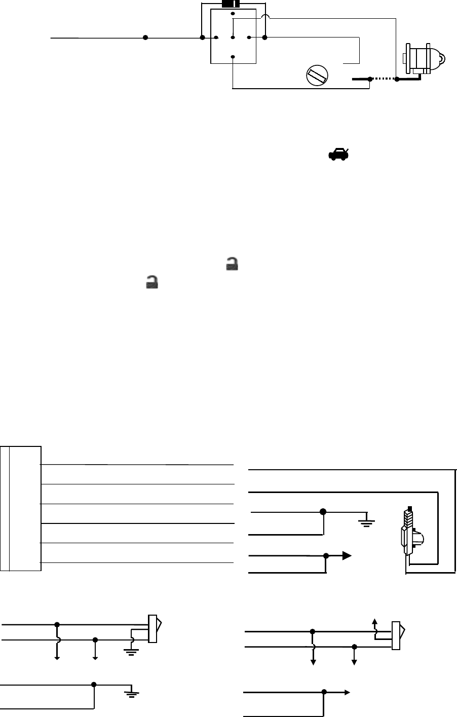
e). Connect the ORANGE Wire from the control module to the ORANGE wire (pin #86) of the relay.
f). Connect the Yellow wire (pin #85) of the relay to a switched 12 volts source from the ignition switch.
NOTE: If more than one electronic device will be connected to the ORANGE Wire, it will be necessary to
isolate the connection of each device control wires with a 1N4003 diode.
OCT/02/2002
CA-120 4
87
87a
85
30
86
IN4003 Diode
H7/5: ORANGE wire
from control module
“Start”
“On”
White wire
X
Cut
Red wire
Orange wire
“Acc”
“Off”
Starter
Yellow wire to
Ignition Switch
H7/6 . Gray wire – (-) 200mA Programmable Output –
CHANNEL 3 OUTPUT (Factory default setting)
This will become a 1 second pulse ground by press and hold the button on transmitter for two
seconds, the current capacity of this wire is 200 mA. this feature allows you to remote control trunk
release or other electric device.
2 STEPS UNLOCK OUTPUT (Set Feature III – 2 Programming to “2 Step Door Unlock Output)
The 2 steps unlock feature will work for the most fully electronic door lock circuit. The vehicle must have
an electronic door lock switch (not the lock knob or key switch), which locks and unlocks all of vehicle's
doors. When wired for this feature, press the button one time will disarm the alarm and unlock the
driver's door only. If, press button two times within 3 seconds, the alarm will disarm and all doors
will unlock.
PAGER OUTPUT (Set Feature
III – 2 Programming to “PAGER Output)
This wire provides a negative output, when the alarm triggered. The current capacity of this wire is
200mA. For optional electrical device in this system, please connected to an additional relay. (I.E. Pager
interface....)
H4: 6 PIN DOOR LOCK CONNECTOR :
Blue/White Wire: (30) - Door Unlock Relay
Blue/Red Wire: (87a) - Door Unlock Relay
Blue/Yellow Wire: (87) - Door Unlock Relay
Green/Red Wire: (87a) - Door Lock Relay
Green/White Wire: (30) - Door Lock Relay
Green/Yellow Wire: (87) - Door Lock Relay
INSTALL NEW DOOR LOCK MOTORS
+12V
Green/ white
Blue/ white
Blue/ red
Green/ red
Green/ yellow
Blue/ yellow
NEGATIVE TRIGGER DOOR LOCK SYSTEM
Blue / white
Green / white
Door Lock
Master
Locking
Switch
Door unlock
Green /
y
ellow
Blue / yellow
POSITIVE TRIGGER DOOR LOCK SYSTEM
Blue / white
Green / white
Door Lock
Master
Locking
Switch
Door unlock
Green /
y
ellow
Blue / yellow
+ 12V
+ 12V
OCT/02/2002
CA-120 5
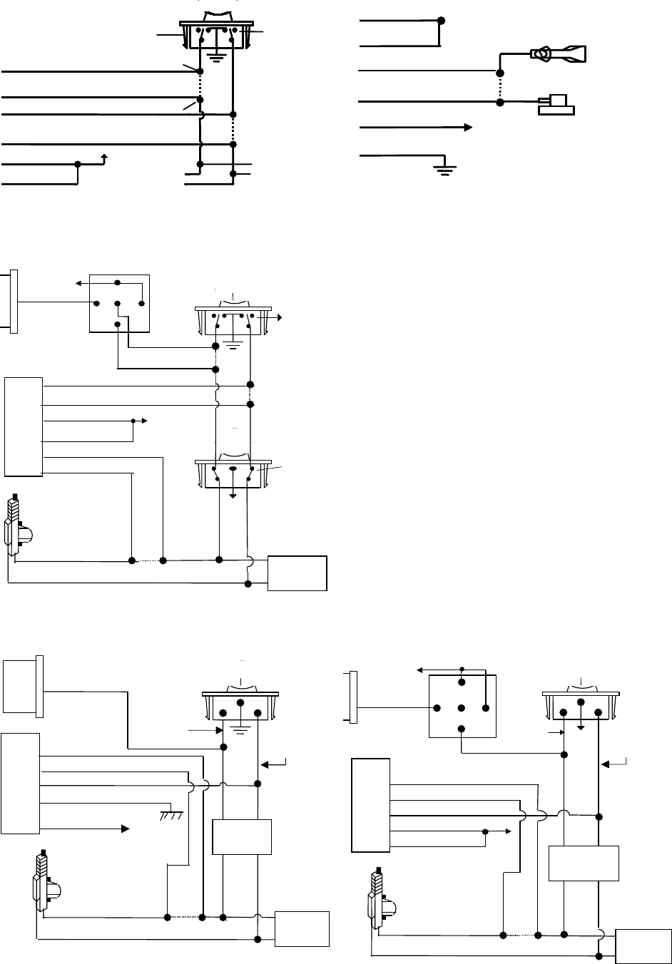
ALTERNATING DOOR LOCKS
+12V
Master Door
Lock Switch
X
X
Splic
Splic Cut the
Existing
Lock Wire
To Door
Lock
To Slave Door
Lock switches
Green/ white
Green/ red
Cut the Existing
Unlock Wire
Blue/ white
Blue/ red
+ 12V
Green/ yellow
Blue/ yellow
VACUUM OPREATE DOOR LOCKING SYSTEM
Green/ white
Blue/ red
Green/ red
Blue/ white
Blue/ yellow
Green/ yellow
+12V
X
Cut
Compressor
Door Switch
2 STEP DOOR UNLOCK WIRE CONNECTION FOR
5 WIRE ALTERNATING DOOR LOCKS
+12V
Cut the Existing
Lock Wire
Green / White
Blue / Red
Green / Red
Cut Existing Unlock
X
Blue / White
Cut the Unlock Wire
Lock
Unlock
OEM Door Master Lock
OEM Slave
Door Lock
Switch
+12V Lock Unlock
To All Other
Door Lock
Motors
H7/6 Gray Wire
x
X
OEM
Door Lock
Motor
Blue / Yellow
Green / Yellow + 12V
+ 12V
85
86 87
87A
30
H4
6-Pin
Door
Lock
Wire
Harness
VACUUM OPERATED DOOR LOCKING SYSTEM:
TYPICAL OF MERCEDES BENZ AND AUDI.
Locate the wire under the driver's kick panel. Use the
voltmeter connecting to ground, verify that you have t
h
correct wire with the doors unlocked, the voltmeter wil
l
receive "12 volts". Lock the doors and the voltmeter w
i
read "0 volt". Move the alligator clip to +12V and the
voltmeter will receive "12 volts". Cut this wire and mak
connections. Be sure to program door lock timer to
3 seconds. (See Feuture II – 1 Programming.)
2 STEP DOOR UNLOCK WIRE CONNECTION FOR
GROUND SWITCHED DOOR LOCKS
Cut Existin
g
Unlock
X
Lock Unlock
OEM Door Master Lock Switch
To All Other
Door Lock
Motor
H7/6 Gray Wire
OEM
Door Lock
Motor
Blue / White
Green / White
Green / Yellow
Existing
Lock Wire
Existing
Unlock Wire
H4
6-Pin
Door
Lock
Wire
Harness
Blue / Red
Blue / Yellow +12V OEM Door
Lock Relay
2 STEP DOOR UNLOCK WIRE CONNECTION FOR
POSITIVE SWITCHED DOOR LOCKS
Cut Existing Unlock
X
Lock Unlock
OEM Door Master Lock
To All Other
Door Lock
Motors
H7/6 Gra
y
Wire
OEM Driver's
Door Lock
Motor
+ 12V
Blue / Red
Existing Pos.
Lock Wire
Existing Pos.
Unlock Wire
30
87A
87
86 85
+12V
Blue / White
Green / White
Green / Yellow
Blue / Yellow + 12V
OEM Door
Lock Relay
H4
6-Pin
Door
Lock
Wire
Harness

OCT/02/2002
CA-120 6
H5: RF ANTENNA - BLACK THIN WIRE :
The black thin wire on control module is the receiver antenna wire. Antenna placement is very important!
Ensure that it is unwrapped and stretched out with the last 6" straight and keep it away from large metal
objects or chassis for best reception.
PROGRAMMING
A. PROGRAMMING TRANSMITTER:
Enter:
1. Turn the Ignition 'switch ‘OFF/ON’ 3 TIMES and stay in ON position. Within 15 seconds.
2. Push the Valet switch 3 times and hold it until a long chirp is hearing then release the valet switch. You
are now in the Transmitter programming mode.
Program:
1. Press button on one of the transmitter until the siren responds with a confirming chirp the first transmitter
is now programmed.
2. Press button on the second transmitter until the siren responds with a confirming chirp, the second
transmitter is now programmed.
3. Apply the same procedure to program 3rd and 4th.
Exit: Turn Ignition to 'OFF' position, or leave it for 15 seconds. A 3 long chirps to confirm exit.
Note: If more than 4 transmitters programmed, the system only kept the last 4 transmitters.
B. ALARM FEATURES PROGRAMMING:
ALARM FEATURE “I” PRORAMMING:
1. Turn the Ignition 'switch ‘ON/OFF’ 3 TIMES and stay in OFF position.
2. Push the Valet switch 2 times and hold it until one chirp with a long chirp is hearing then release the
valet switch. You are now in the Alarm feature ‘I’ programming mode.
3. Press and release the transmitter button ‘A’ corresponding to the feature ‘A’ you want to change.
a. The siren chirps and LED pause will indicate newly setting.
b. The system would advance to [2] LED flash, [2] chirp. (The factory default settings is always [1] LED
flash, [1] chirp.)
4 Depress the transmitter button ‘A’ again to change the feature again. Simple keep re-depressing the
transmitter button ‘A’ again until the module advances to your desired setting.
5. Depress the transmitter button ‘B’ corresponding to the feature ‘B’ you want to program.
Press
Transmitter
Button
One Chirp /
LED one pulse
Factory Default Setting
Two Chirps /
LED two pulse
1 Chirps on Chirps off
OCT/02/2002
CA-120 7
2 Automatic Rearm On Automatic Rearm Off
3 With Door Ajar error chirp. Bypass Door Ajar error chirp
Exit: Turn Ignition to 'ON' position, or leave it for 15 seconds. A 3 long chirps to confirm exit.
ALARM FEATURE “II” PRORAMMING:
1 Turn the Ignition 'switch ‘ON/OFF’ 3 TIMES and stay in OFF position.
2 Push the Valet switch 4 times and hold it until two chirps with a long chirp is hearing then release the
valet switch. You are now in the Alarm feature ‘II’ programming mode.
3 Press and release the transmitter button ‘A’ corresponding to the feature ‘A’ you want to program.
Press
Transmitter
Button
One Chirp /
LED one pulse
Factory Default Setting
Two Chirps /
LED two pulse
Three Chirps /
LED three pulse
1 0.9-second Door lock
pulses.
3.0-second Door lock
pulse.
Double pulse unlock
2 Active arming Passive arming without
passive door locking
Passive arming with
passive door locking.
3 Ignition controlled door locks
& unlocks
Without ignition controlled
door locks & unlocks
Exit: Turn Ignition to 'ON' position, or leave it for 15 seconds. A 3 long chirps to confirm exit.
ALARM FEATURE “III” PRORAMMING:
1 Turn the Ignition 'switch ‘ON/OFF’ 3 TIMES and stay in OFF position.
2 Push the Valet switch 6 times and hold it until three chirps with a long chirp is hearing then release the
valet switch. You are now in the Alarm feature ‘III’ programming mode.
3 Press and release the transmitter button ‘A’ corresponding to the feature ‘A’ you want to program.
Press
Transmitter
Button
One Chirp /
LED one pulse
Factory Default Setting
Two Chirps /
LED two pulse
Three Chirps /
LED three pulse
1 H1/5 Brown Wire = Siren
Output
H1/5 Brown Wire = Horn
Output
2 H7/6 Gray Wire = Trunk
(Channel 3) Output
H7/6 Gray Wire = Two
Step Door Unlock Output
H7/6 Gray Wire = Pager
Output
3 Car Jacking Off Car Jacking On
Exit: Turn Ignition to 'ON' position, or leave it for 15 seconds. A 3 long chirps to confirm exit.
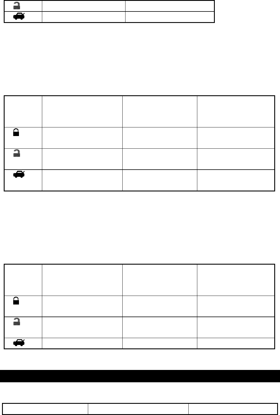
OPERATION MANUAL
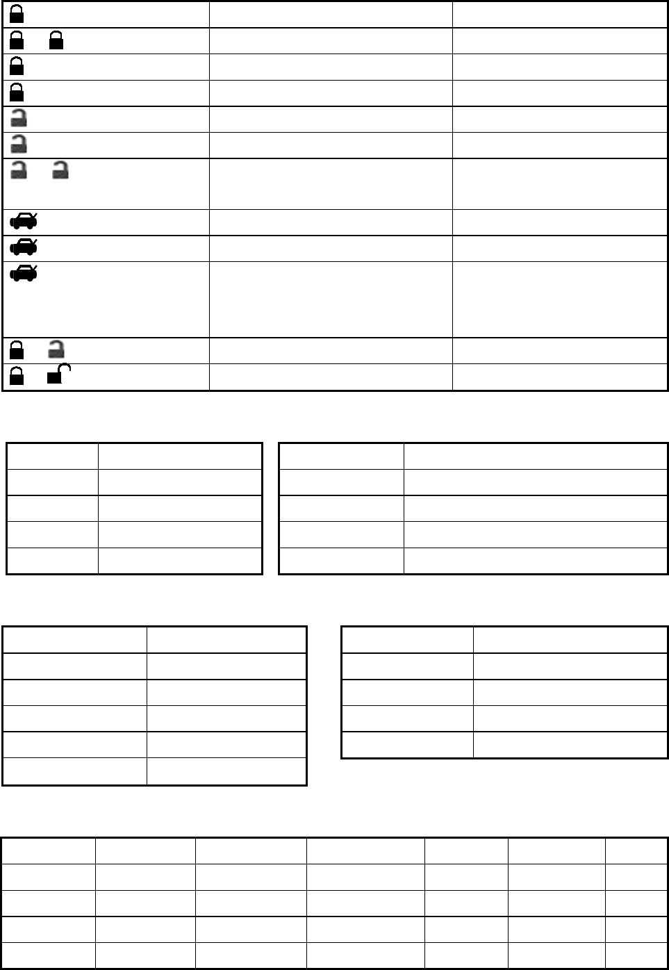
A. TRANSMITTER OPERATION :
Transmitter Button System Function Remark
OCT/02/2002
CA-120 8
Button Arm / Lock door
– Button Arm and Delete Optional Sensor Press twice.
Button Car Locator System in Armed.
Button for 3 seconds Panic function Press 3 seconds
Button Disarm & Unlock Door
Button for 2 seconds Disarm & Trunk Release Press and Hold for 2 seconds
– Button Two Steps Door Unlock & Disarm
System
Press twice within 3 seconds.
Button Car Locator
Button for 2 seconds Pop Trunk Release Press 2 seconds
Button for 3 seconds Panic function If the H7/6 Gray Wire is not
Trunk release Output (See
Alarm Feature III-2)
+ Button Silent Arm / Disarm Ignition in "off" position.
+ Button for 2 seconds Activate Car-Jacking Ignition in "on" position.
B. LED INDICATORS:
LED Function LED Function
Off Disarmed 2 flashes... pause Trigger on trunk/hood
Slow flash Armed 3 flashes... pause Trigger on door switch
Fast flash Passive arming 4 flashes... pause Trigger on Dual Zone Shock Sensor
On (solid) Valet mode 5 flashes... pause Trigger on Ignition switch
C. CHIRP INDICATORS : D. PARKING LIGHT :
Chirp Function Parking light Function
1 chirp Arm 1 flash Arm
2 chirps Disarm
2 flashes Disarm
3 chirps Defective reminder 3 flashes Disarm / Intrusion
4 chirps Disarm / Intrusion 12 flashes Car Locator
6 chirps Car Locator
E. ALARM OPERATING CONDITION :
Siren Parking Light LED Doors Starter disable Pager
1. Arming 1 Chirp 1 Flash Slow flash Locking On
2. Disarming 2 or 4 Chirps 2 or 3 Flashes Off or Fast flash Unlocking Off
3. Trigger Alarming Flashes Slow flash On On
4. Panic Alarming Flashes Slow flash Locking On

OCT/02/2002
CA-120 9
F. ACTIVE ARMING – LOCK & ARM :
1. Press button on transmitter.
2. The siren will chirp once and parking light will flash once indicating that the system is now armed. The
vehicle doors will lock upon arming when interfaced with the security system.
Note: Defective sensor reminder: If the siren sounds 3 chirps, then you have left a door, trunk, or hood
lid ajar. (See Feature “I - 3 Programming)
SILENT ARMING / DISARMING: Press the + button together on the transmitter will arm or
disarm your security system, No chirp sound will be heard, arm / disarm confirmation will be through the
vehicles parking lights only.
SHOCK SENSOR / OPTIONAL SENSOR BY-PASS: Press the button on the transmitter twice within
3 seconds will arm the security system, by-pass the shock sensor and the optional sensor connected to 4
pin plug. The system will chirp one additional time to confirm the sensor bypass mode was activated. The
sensor bypass feature is programmed to activate for one arming cycle only. The security system will return
to normal operation during the next arming cycle.
G. PASSIVE ARMING : (See Feature “II - 2” Programming)
Active arming / disarming is controlling your security system via the remote transmitter. This security
system is equipped with an optional Passive Arming feature, which allows the security system to arm 30
seconds after the last door is closed. Operation is as follows.
1. Turn the ignition to the “OFF” position and exit the vehicle.
2. After all entrances are closed, the security system LED will flash fast for 30 seconds. If you reopen any
door / hood / trunk, the security system LED will stop flashing. It will begin flashing again once the
vehicle all entrances are closed.
3. After 30-second timer has elapsed, the security system will automatically “ARM”. The siren will chirp [1]
time and the parking lights will flash [1] time.
PASSIVE DOOR LOCKING: (See Feature “II - 2” Programming)
The vehicle doors will automatically lock after passive arming cycle has been completed.
H. ACTIVE DISARMING – UNLOCK & DISARM :
1. Press the button on the transmitter.
2. The siren will chirp twice and parking light will flash twice to indicating that the security system is now
disarmed. The vehicle doors will unlock disarming when interfaced with the security system.
TAMPER DISARMING: If alarm triggered, upon disarm the system, siren chirp 4 times, parking light flash
3 times.
TWO STEP DOOR UNLOCK: (See Feature III – 2 Programming.) This feature will independently unlock
the drives door only when disarming the security system. Pushing the button on the transmitter a
second time within 3 seconds will unlock the entire vehicle.
AUTOMATIC RE-ARM (See Feature “I - 2” Programming): If this feature is selected, the security system
will automatically re-arm itself 60 seconds after disarming with remote transmitter. Automatic rearm will
cancel if any door is opened before the 60 seconds timer has elapsed.

OCT/02/2002
CA-120 10
I. DISARMING WITHOUT A TRANSMITTER
The Override function may be used if the remote transmitter is lost or inoperative.
1. Enter the vehicle and turn the ignition switch to 'ON’ position. (Alarm will sound.)
2. Within 10 seconds push and release the valet switch
The alarm will stop sounding and enter the disarm mode. You can now start and operate the vehicle
normally.
J. VALET MODE :
The valet switch allows you to temporarily bypass all alarm function, eliminating the need to hand your
transmitter to parking attendants or garage mechanics. When the system is in valet mode, all alarm
function are bypassed, however the remote panic feature and remote door locks will remain operational.
Enter Valet Mode: 1. Turn the ignition to “ON” position.
2. Push and hold valet switch for 2 seconds until the LED turns on. The LED wills
remain on as long as the system is in 'valet mode'.
Exit Valet Mode: 1. Return to normal operation, turn ignition 'ON'.
2. Push and hold valet switch for 2 seconds, The LED wills turns off indicate the
system are exiting the valet mode.
K. PANIC FUNCTION :
The transmitter can be used as a remote panic switch to manually trigger the alarm in case emergency.
1. Press and hold the button on the transmitter for 3 seconds. The alarm will immediately sound.
2. To stop the alarm, press and hold the or button on the transmitter, the panic mode will be
turned off immediately.
3. If the button is not pressed, the alarm will automatically stop after 30 seconds.
Note: If the H7/6 Gray Wire is not Trunk release Output, (See Alarm Feature III-2 Programming), Press
and hold the button on the transmitter for 3 second. The alarm will immediately sound.
L. TRIGGER THE SYSTEM :
When armed, your vehicle is protected as follows:
1. Light impacts will trigger the warn-away signal. A long chirp from siren/horn.
2. Heavy impacts / Doors open / Hood open / Trunk open / Turns on the ignition switch will trigger the
programmed sequence.
The starter disable relay (if installed) prevents the vehicle’s starter from cranking. The siren and parking
lights will turn on to alerting of an intrusion for 30 seconds. Then it will stop and automatic reset and re-arm.
If the one of sensors or detectors still active, the alarm system will sound a maximum of 6 times of 30
seconds cycles.
M. ANTI CAR-JACKING :

OCT/02/2002
CA-120 11
Warning: If you don't need the car jacking function in this alarm system, be sure to set car jacking feature
“OFF”. This system is default setting car-jacking “OFF”. (See Alarm Feature III - 3 Programming.)
1. TRANSMITTER ACTIVATE THE CAR JACKING:
Press and hold the transmitter and button at the same time for 1 seconds while the vehicle’s
ignition is “ON”. The parking lights will turn on for 1.5 seconds to indicate car jacking activated.
2. DOOR SWITCH ACTIVATE CAR JACKING:
1. Turn the ignition switch to “ON” position, the system is armed.
1. Once the system is armed, If you are forced from the vehicle, the system will active the car jacking
trigger when the door is opened and closed while the ignition is “ON”.
TRIGGER THE CAR JACK MODE:
3-timer circuits will function as follows:
First timer: a. 50 seconds after the system has been triggered. The siren will start chirping for 15 seconds.
b. During this 15 seconds period of chirping, you will be alerting to push the valet switch once
to turn off the car-jacking feature.
c. If not, it will enter second timer car jacking.
Second timer: 65 seconds after the system has been triggered. The siren starts alarming and the parking
light starts flashing.
Third timer: 90 seconds after the system has been triggered
a. The siren still alarming and the parking light flashing, and
b. The starter disable will activate to prevent the vehicle from starting.
c. It will remain active until the vehicle's battery power exhausted.
OVERRIDE THE SYSTEM TO TURN OFF CAT JACKING:
Turn the ignition switch from OFF to ON, and within 10 seconds push valet switch, the siren will stop and
the system disarmed
O. IGNITION CONTROL DOOR LOCKS : (See Feature II – 3 Programming.).
If the vehicles door locks have been interfaced to the security system, the system will automatically lock
the vehicle's doors when the ignition is turned “ON” and /or unlock the vehicle’s doors when the ignition is
turned “OFF”.
P. TRUNK RELEASE : (See Feature III – 2 Programming.).
Press and hold button on transmitter for two seconds to remote control the trunk release or other
electric devices.
Q. CAR LOCATOR :
Press the button on the transmitter to active car locator function. The siren will chirp 6 times. The
parking light will flash 12 times, for you to easily locate your car.
OCT/02/2002
CA-120 12
This device complies with part 15 of the FCC rules. Operation is subject to the following two conditions.
(1) This device may not cause harmful interference, and
(2) This device must accept any interference received, including interference that may cause undesired
operation.
CAUTION: Changes or modifications not expressly approved by the
manufacturer responsible for compliance could void the user’s authority to
operate the equipment