Code Systems PC2000 Auto security transmitter User Manual 100414 8
Code Systems Inc Auto security transmitter 100414 8
UserManual.wiki
>
Code Systems
>
PC2000 User Manual
>
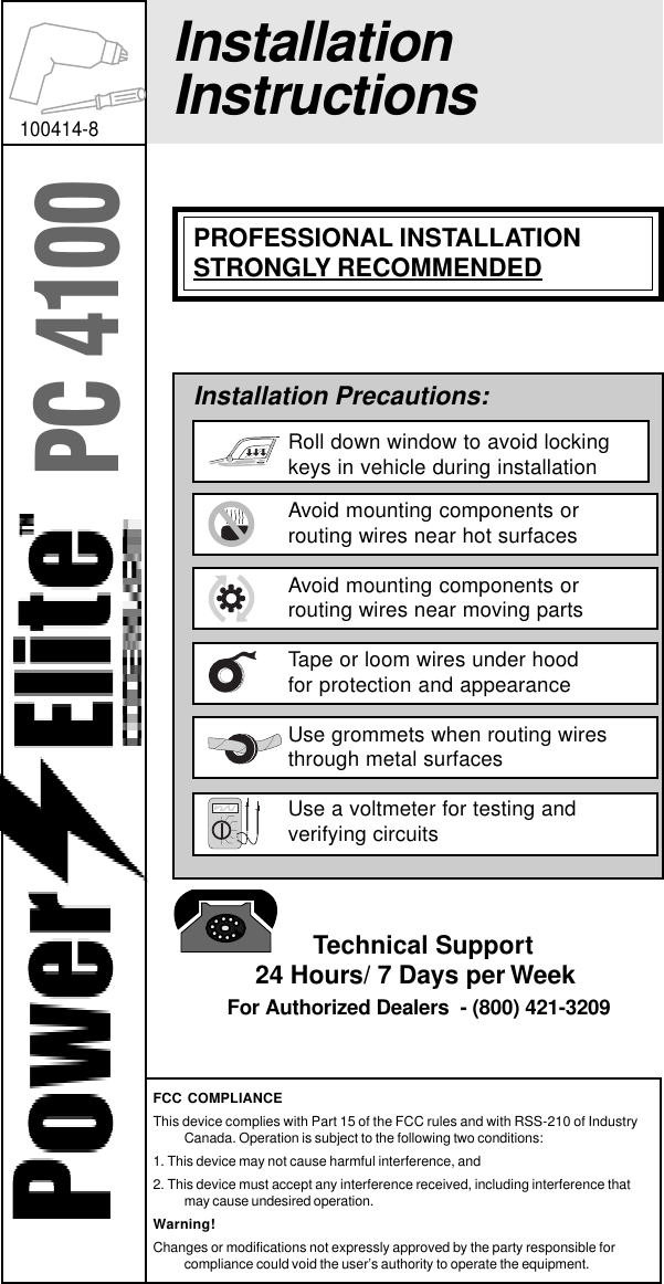
Installation manual
Contents
1.
Users manual
2.
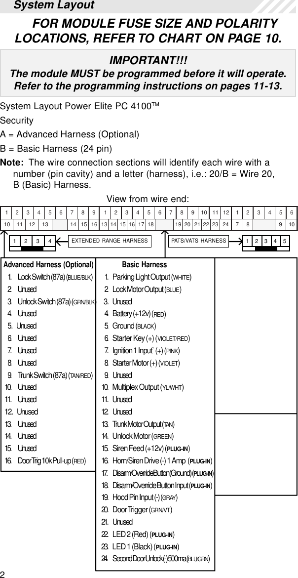
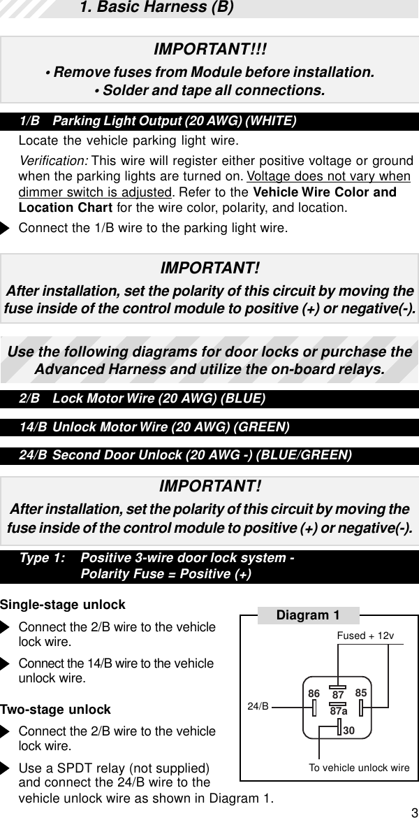
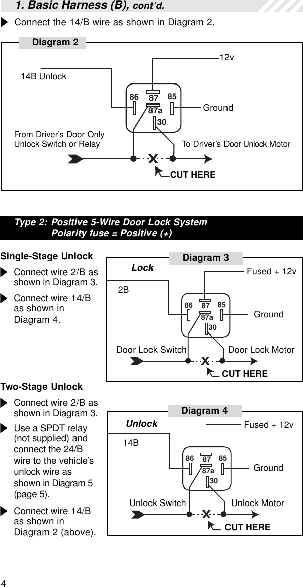
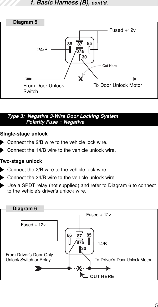
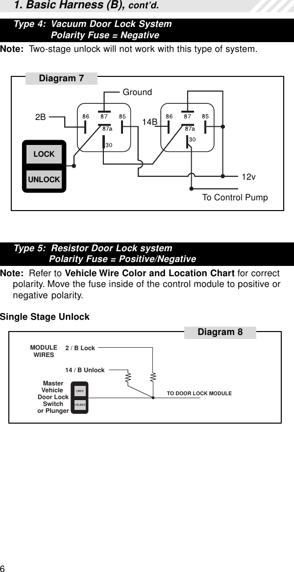
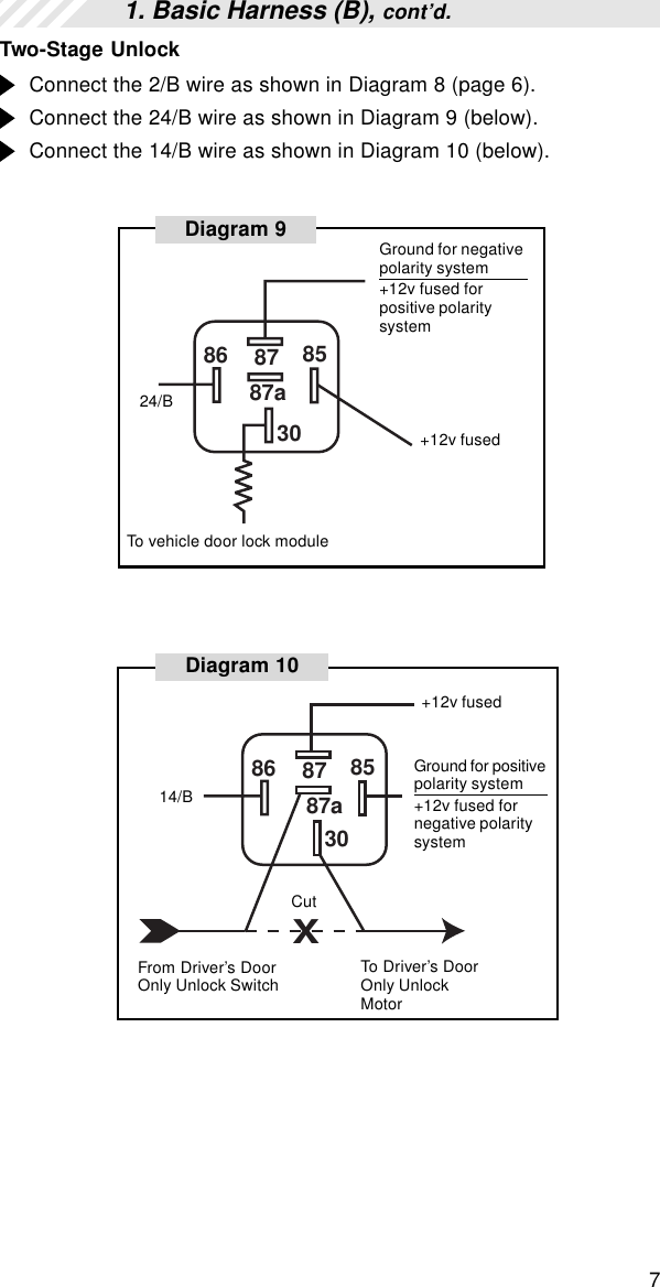
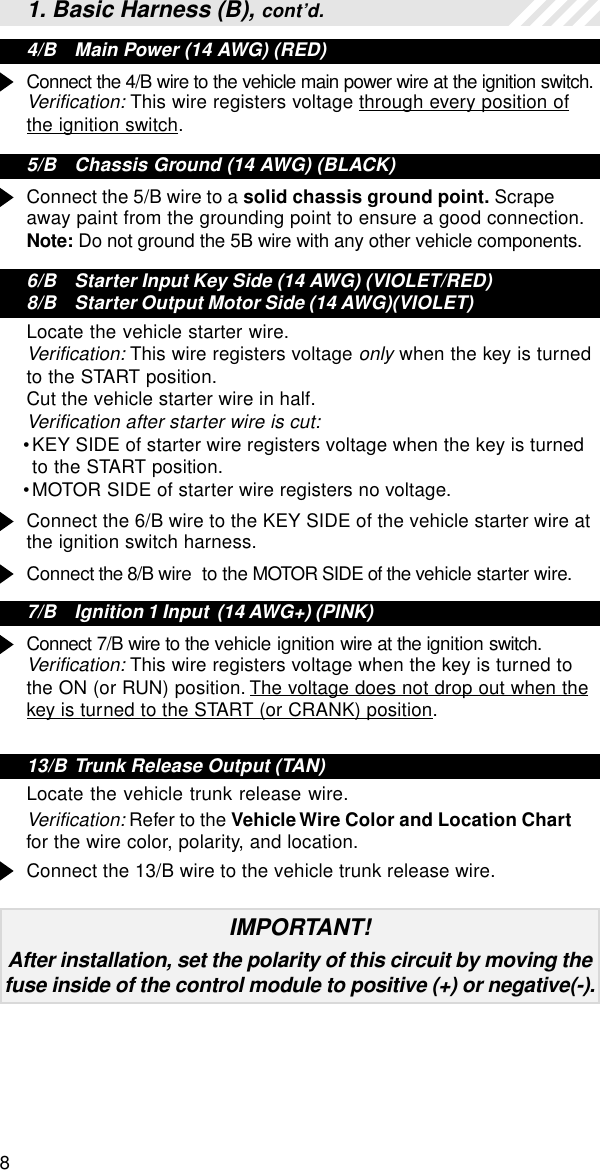
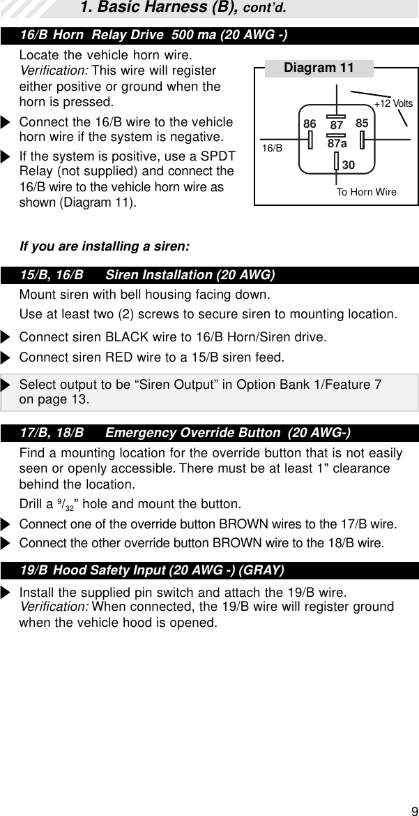
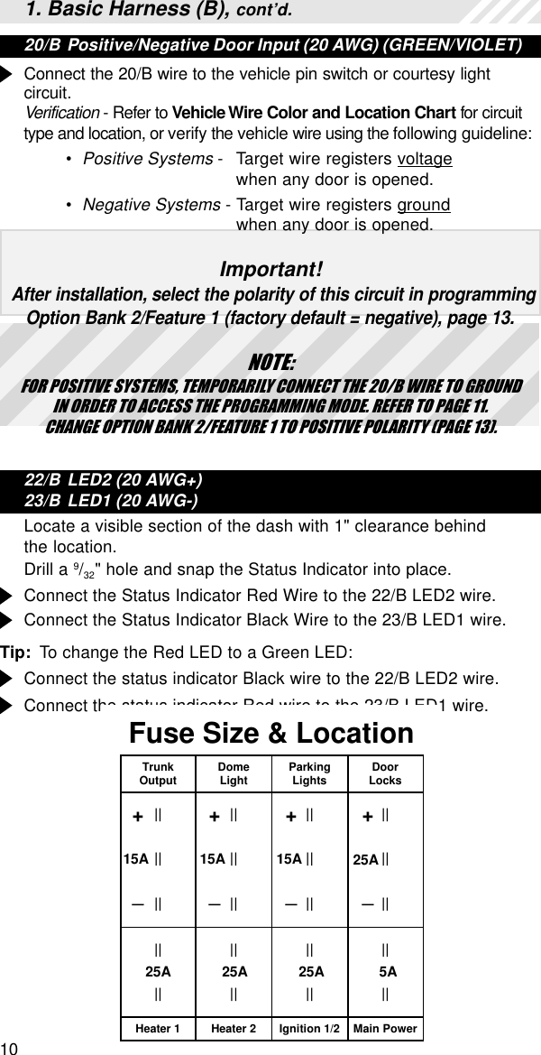
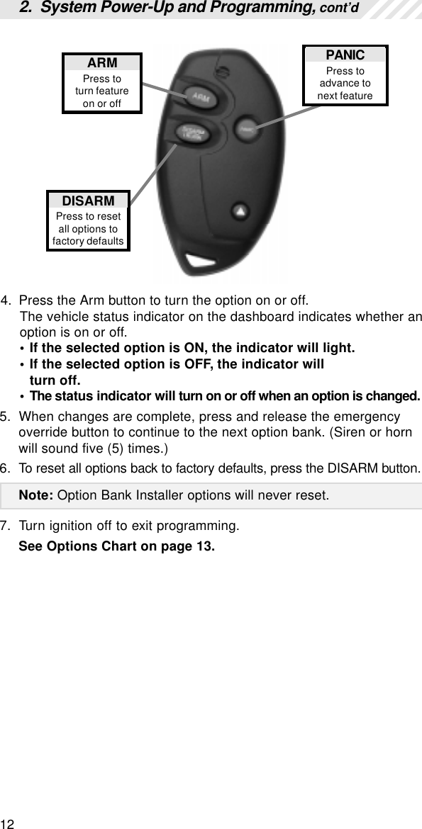
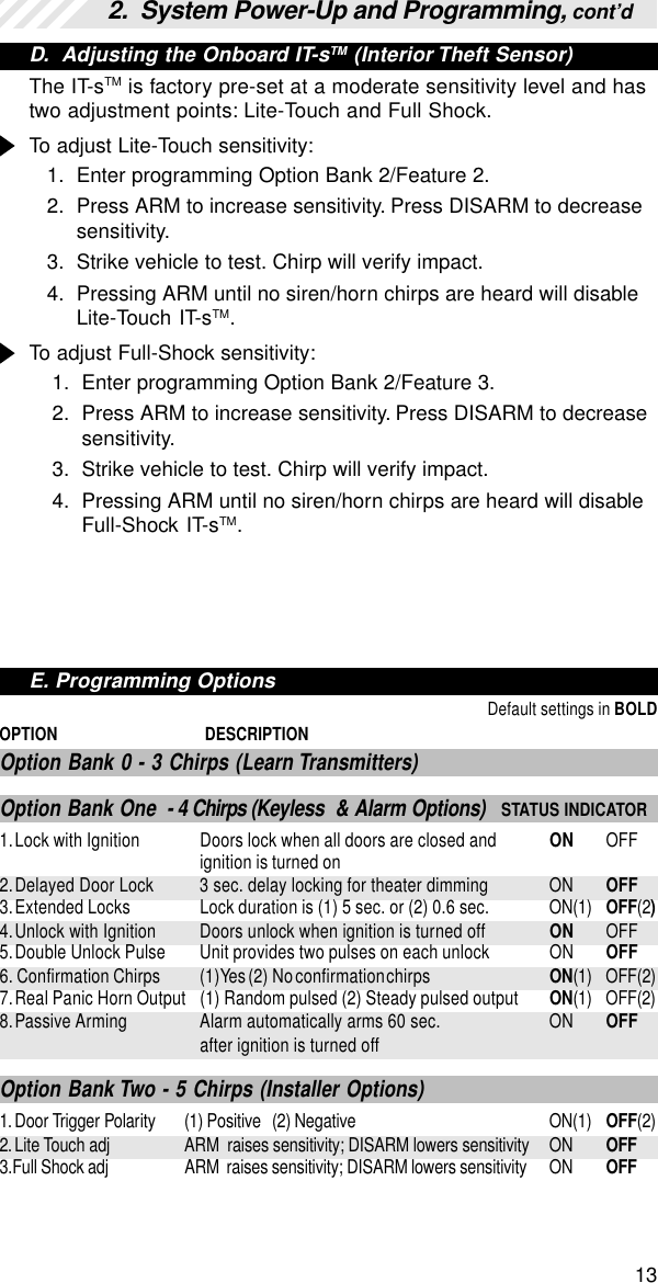
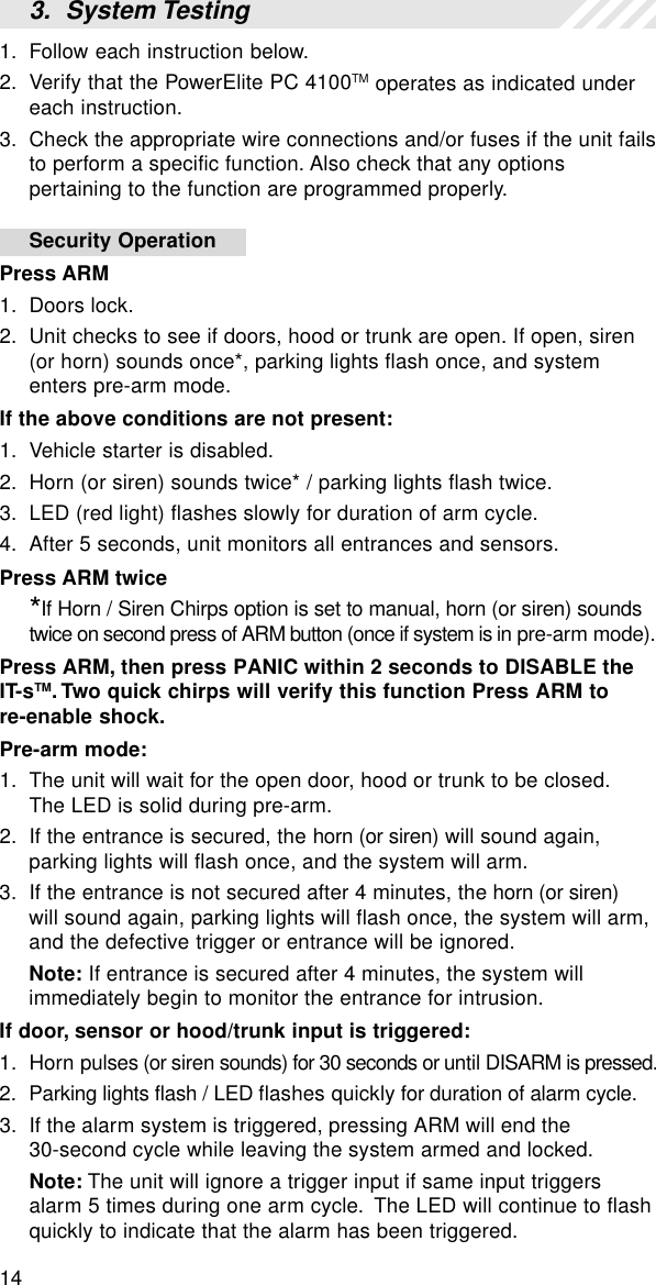
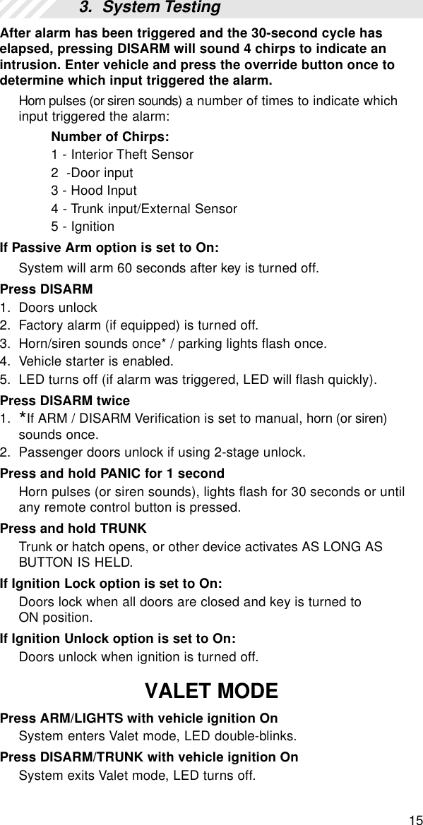
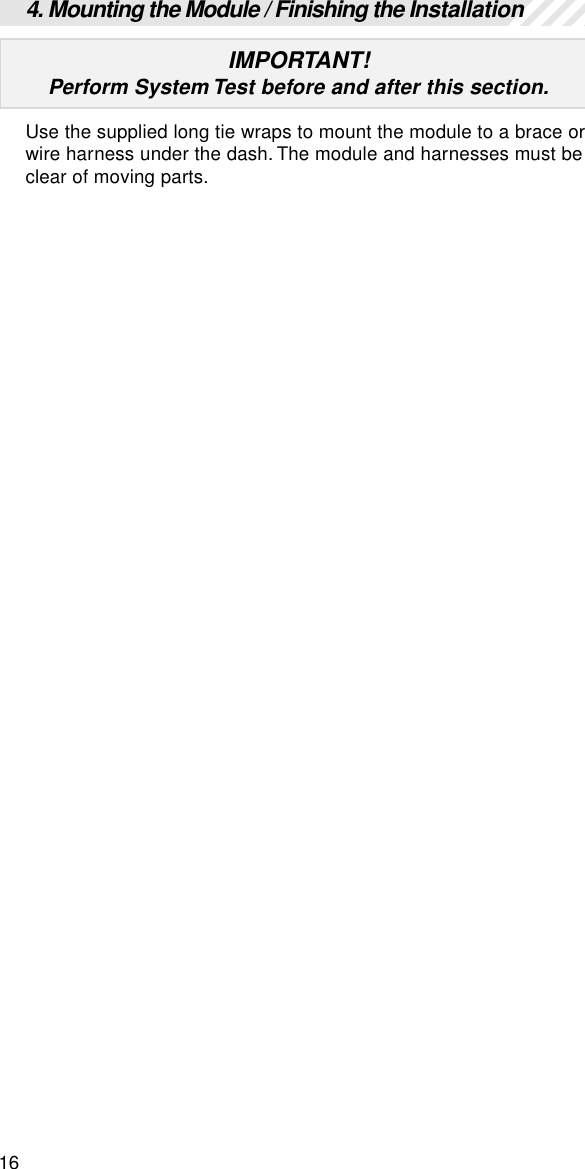
Installation manual
Installation manual
Navigation menu
Upload a User Manual
Namespaces
Wiki Guide
HTML
PDF
Info
Views
User Manual
Discussion / Help
Navigation