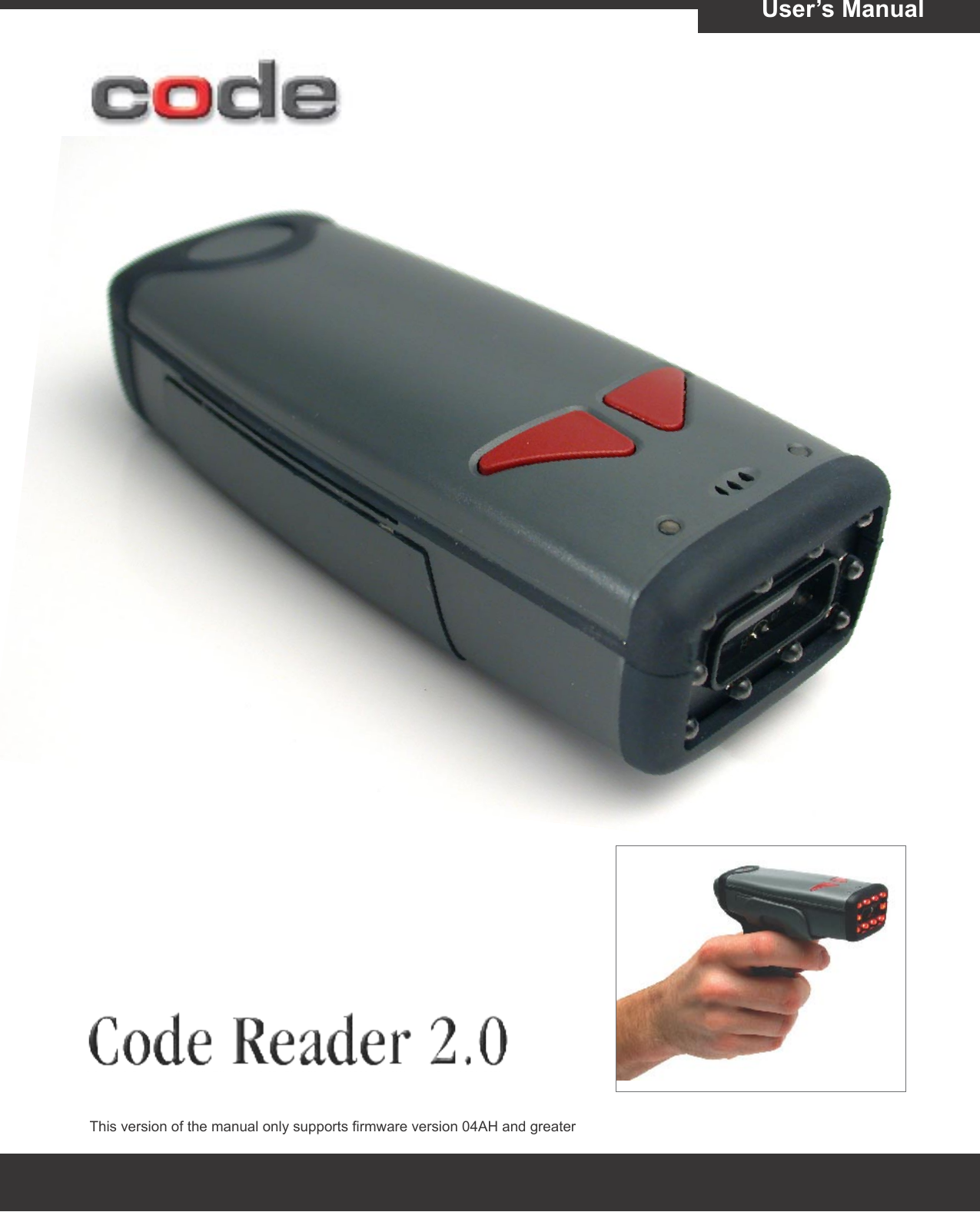
Code CR201 Model: CR2 - Handheld Barcode Reader User Manual
Code Corporation Model: CR2 - Handheld Barcode Reader Users Manual
UserManual.wiki
>
Code
>
CR201 User Manual
Users Manual
Navigation menu
Upload a User Manual
Namespaces
Wiki Guide
HTML
PDF
Info
Views
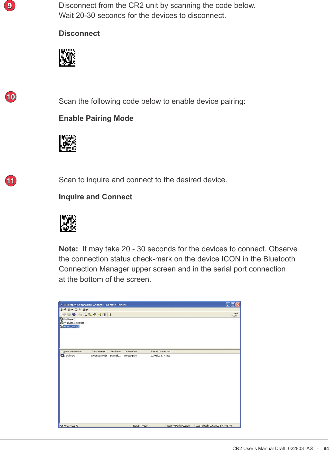
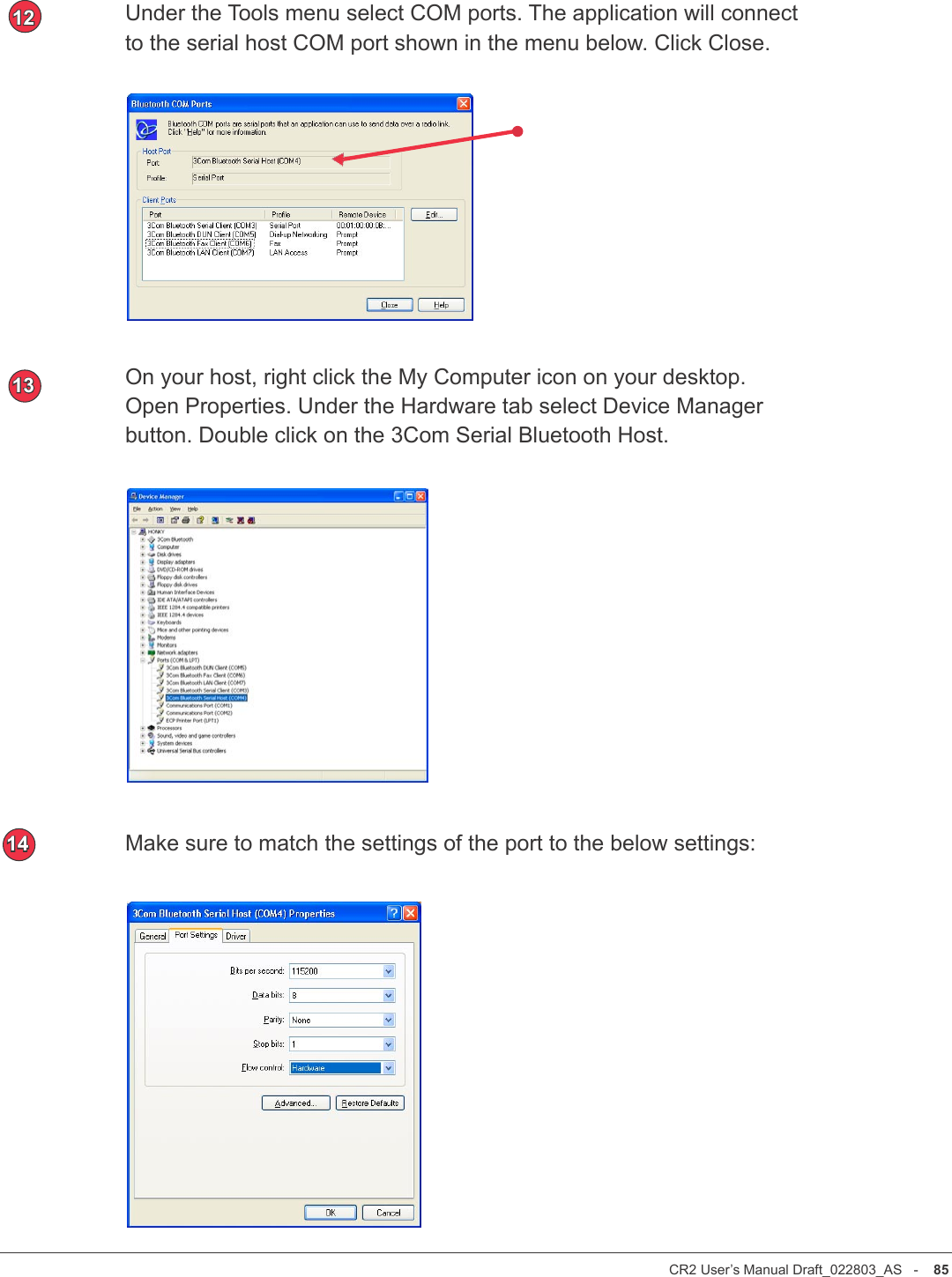
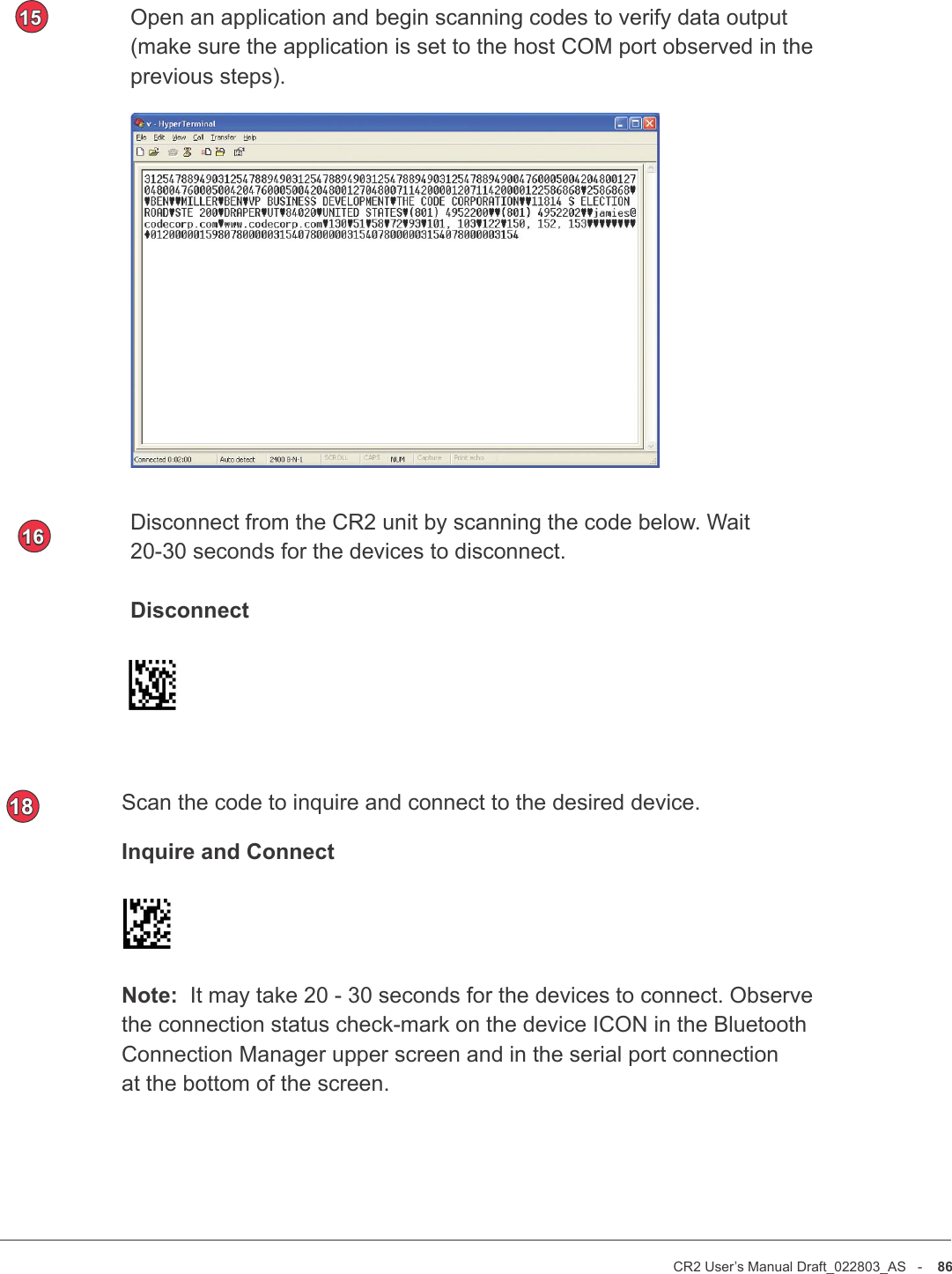
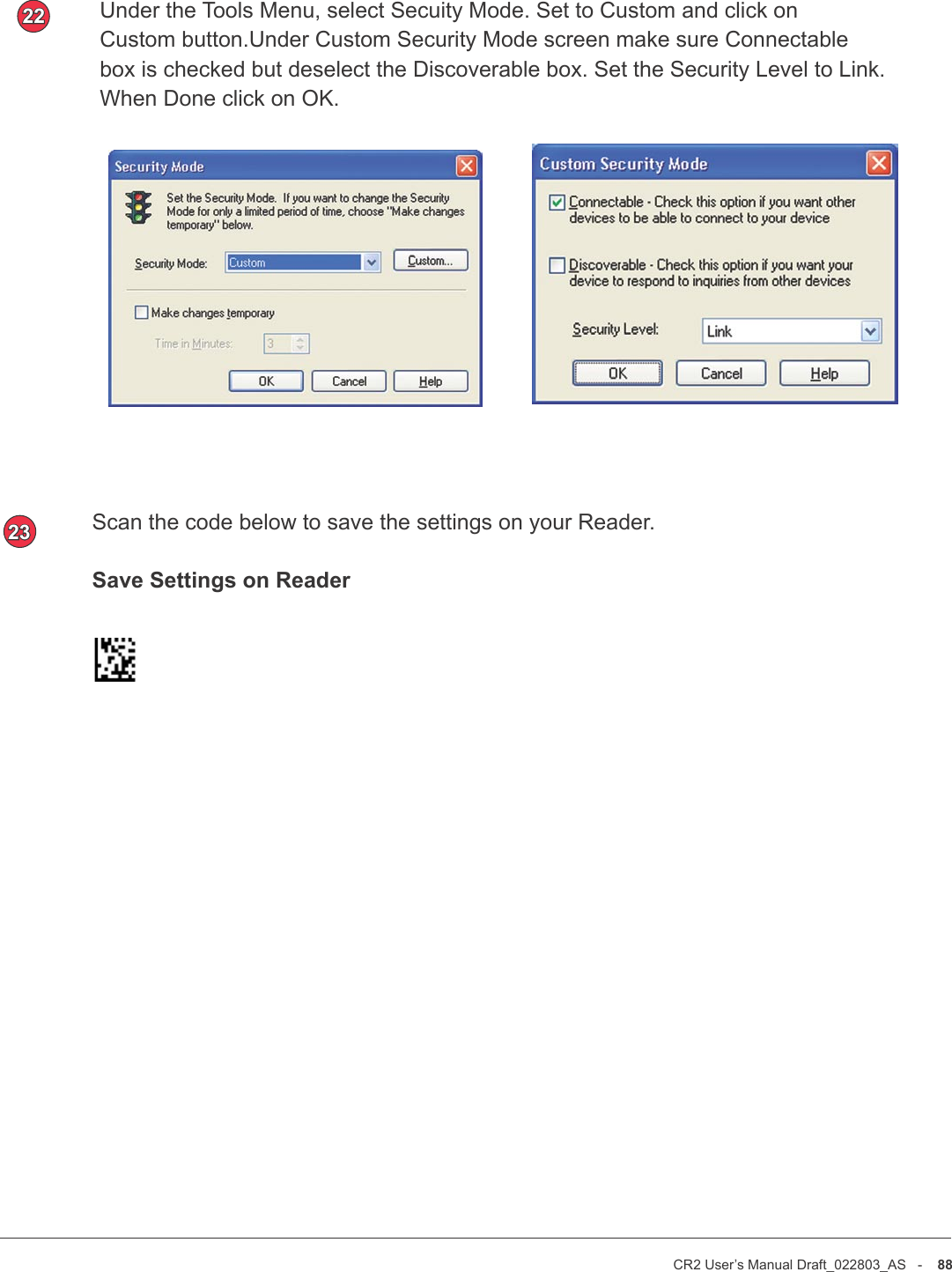
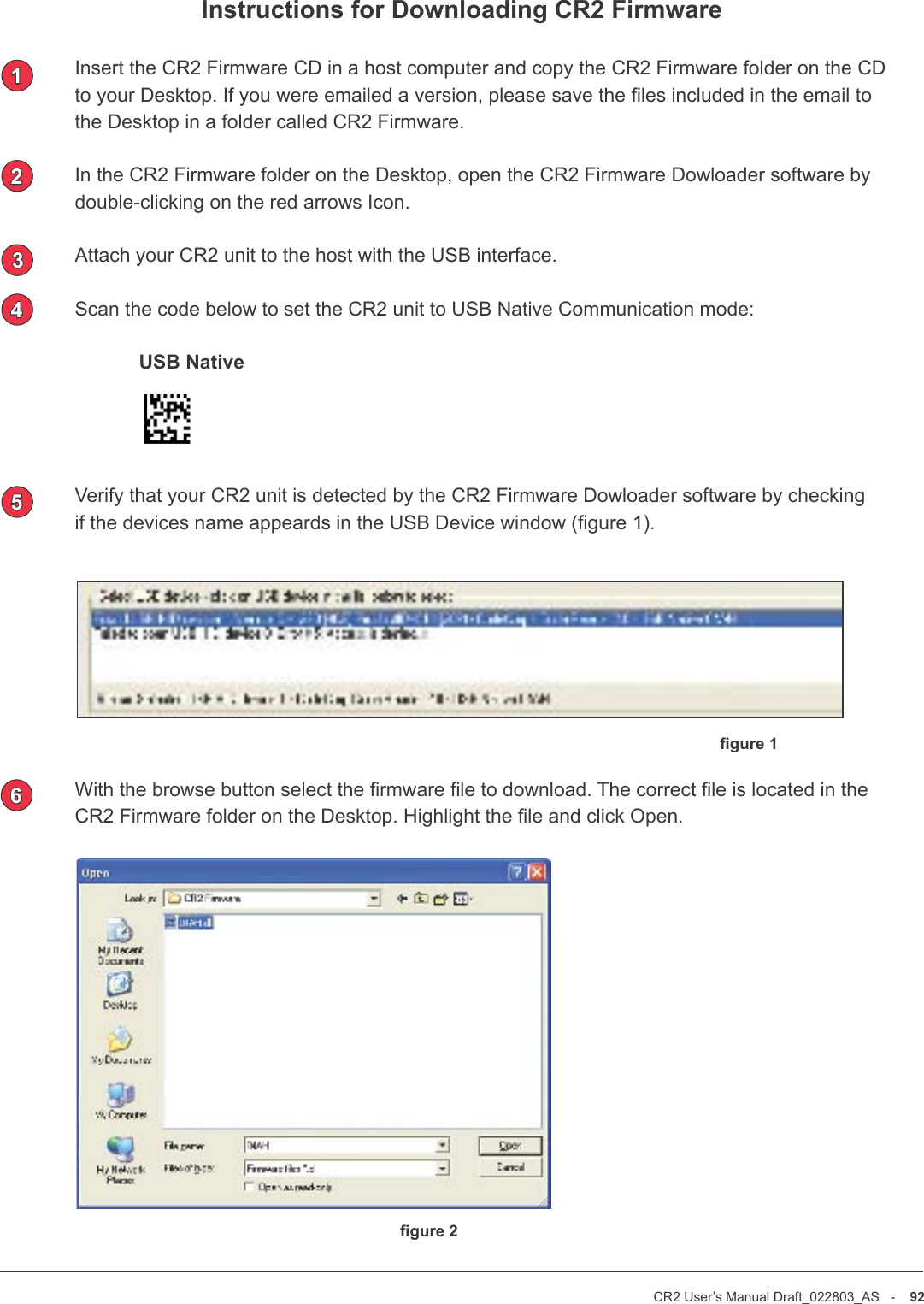
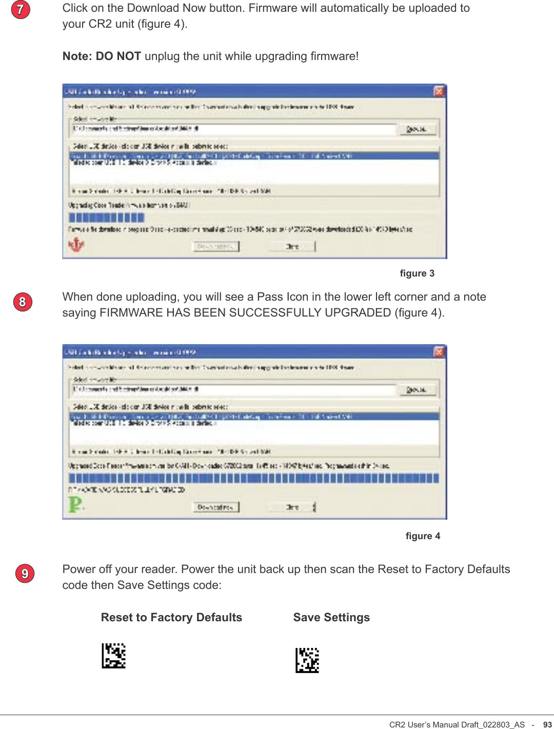
User Manual
Discussion / Help
Navigation