Code CR201 Model: CR2 - Handheld Barcode Reader User Manual
Code Corporation Model: CR2 - Handheld Barcode Reader Users Manual
Code >
Users Manual

CR2 User’s Manual Draft_022803_AS - 1
User’s Manual
This version of the manual only supports rmware version 04AH and greater

CR2 User’s Manual Draft_022803_AS - i
Statement of Agency Compliance
The Code Reader 2.0 can be set to use targeting lasers.
If the targeting lasers are activated, do not stare into the beams.
The Code Reader’s targeting lasers have been rated as Class 2
Lasers by ANSI 2136.1-1993.
The Code Reader 2.0 has been tested by an independent
electromagnetic compatibility laboratory in accordance with
the applicable specications and instructions.
The Code Reader 2.0 has been tested for compliance with FCC
regulations and was found to be compliant with all applicable FCC
Rules and Regulations.
IMPORTANT NOTE: To comply with FCC RF exposure compliance
requirements, this device must not be co-located or operate in
conjunction with any other antenna or transmitter.
CAUTION: Changes or modications not expressly approved by
the party responsible for compliance could void the user’s authority
to operate the equipment.
The Code Reader 2.0 has been tested for compliance to CE
standards and guidelines and was found to conform to applicable
CE standards, specically the EMC requirements EN 55024, ESD
EN 61000-4-2, Radiated RF Immunity EN 61000-4-3, ENV 50204,
EFT EN 61000-4-4, Conducted RF Immunity EN 61000-4-6, EN
55022, Class B Radiated Emissions, and Class B Conducted
Emissions.

CR2 User’s Manual Draft_022803_AS - ii
CR2 User’s Manual Draft_022803_AS - iii
Code Reader 2.0 User’s Manual
Copyright © 2003 the Code Corporation.
All Rights Reserved.
The software described in this manual may only be used in accordance with the terms of its license
agreement.
No part of this publication may be reproduced in any form or by any means without written permission
from the Code Corporation. This includes electronic or mechanical means such as photocopying or
recording in information storage and retrieval systems.
NO WARRANTY. This technical documentation is provided AS-IS. Further, the documentation does
not represent a commitment on the part of The Code Corporation. The Code Corporation does not
warrant that it is accurate, complete or error free. Any use of the technical documentation is at the risk
of the user. The Code Corporation reserves the right to make changes without prior notice. The Code
Corporation does not assume any product liability arising out of or in connection with the application or
use of any product or application described herein.
NO LICENSE. No license is granted, either by implication, estoppel, or otherwise under any intellectual
property rights of The Code Corporation. Any use of hardware, software and/or technology of the Code
Corporation is governed by its own agreement.
The following are trademarks or registered trademarks of the Code Corporation:
CodeXML, Maker, QuickMaker, CodeXML Maker, CodeXML Maker Pro, CodeXML Router, CodeXML
Client SDK, CodeXML Filter, HyperPage, CodeTrack, GoCard, GoWeb, ShortCode, GoCode
All other product names mentioned in this manual may be trademarks of their respective companies and
are hereby acknowledged.
The software and/or products of The Code Corporation include inventions that are patented or that are
the subject of patents pending.
The Code Corporation, 11814 S. Election Road, Suite 200, Draper, UT 84020
www.codecorp.com

CR2 User’s Manual Draft_022803_AS - ii
CR2 User’s Manual Draft_022803_AS - iii
Chapter 1 - CR2 Overview
1.1 Introduction ......................................................................................................................2
1.2 Unpacking ........................................................................................................................3
1.3 General Safety Information ..............................................................................................4
1.4 Warranty and Service Information.................................................................................5-6
1.5 Targeting and Reading Techniques ...............................................................................7-8
1.6 CR2 Accessories ..............................................................................................................9
Chapter 2 - Getting Started
2.1 Minimum Requirements ................................................................................................. 11
2.2 Installation Guides
- USB Interface...........................................................................................................12
- RS-232 Interface......................................................................................................13
- Batch Interface (Store and Forward)...................................................................14-15
- Cordless Interface (Bluetooth Radio)..................................................................16-19
2.3 Switching Cables............................................................................................................20
2.4 Attaching Handle............................................................................................................21
2.5 CR2 Battery and Battery Blank ......................................................................................22
2.6 CR2 Feedback Denition Guide................................................................................23-24
Chapter 3 - Symbology Programming
3.1 Introduction ....................................................................................................................26
3.2 Aztec Symbology
- Enable/Disable Decoding.........................................................................................27
- Enable/Disable Inverse Decoding............................................................................27
3.3 Codabar Symbology
- Enable/Disable Decoding.........................................................................................28
- Check Checksum.....................................................................................................28
- Don’t Check Checksum ...........................................................................................28
3.4 Code 128 Symbology
- Enable/Disable Decoding.........................................................................................29
3.5 Code 93 Symbology
- Enable/Disable Decoding.........................................................................................30
Table of Contents

CR2 User’s Manual Draft_022803_AS - iv
CR2 User’s Manual Draft_022803_AS - v
3.6 Code 39 Symbology
- Enable/Disable Decoding..................................................................................31
- Enable/Disable Full ASCI Decoding..................................................................31
- Check Checksum..............................................................................................31
- Don’t Check Checksum ....................................................................................31
3.7 Composite Symbologies
- Enable/Disable Decoding..................................................................................32
3.8 Data Matrix Symbology
- Enable/Disable Decoding..................................................................................33
- Enable/Disable Inverse Decoding.....................................................................33
- Enable/Disable Rectangle Decoding ................................................................33
3.9 GoCode Symbology
- Enable/Disable Decoding..................................................................................34
3.10 Interleaved 2 of 5 Symbology
- Enable/Disable Decoding..................................................................................35
3.11 Maxicode Symbology
- Enable/Disable Decoding..................................................................................36
3.12 MSI Plessy Symbology
- Enable/Disable Decoding..................................................................................37
3.13 PDF 417 Symbology
- Enable/Disable Decoding..................................................................................38
3.14 Micro PDF417 Symbology
- Enable/Disable Decoding..................................................................................39
3.15 Postal Symbologies
- Enable/Disable Decoding..................................................................................40
3.16 QR Code Symbology
- Enable/Disable Decoding..................................................................................41
- Check Checksum..............................................................................................41
- Don’t Check Checksum ....................................................................................41
3.17 RSS Symbology
- Enable/Disable Decoding..................................................................................42
3.18 UPC/EAN/JAN Symbologies
- Enable/Disable Decoding..................................................................................43
Table of Contents

CR2 User’s Manual Draft_022803_AS - iv
CR2 User’s Manual Draft_022803_AS - v
Table of Contents
Chapter 4 - CR2 Advanced Programming
4.1 Communication Settings
- USB Settings.......................................................................................................... 45
- RF Settings ............................................................................................................ 46
- RS-232 Settings..................................................................................................... 47
• Data Bit...................................................................................................... 48
• Stop Bit Data ............................................................................................. 49
• Baud Rate.................................................................................................. 50
• Parity ......................................................................................................... 51
4.3 Prex / Sufx ................................................................................................................ 52
4.4 Reader ID and Firmware Version ................................................................................. 53
4.5 Time Stamp Settings .................................................................................................... 54
4.6 Batch Mode Settings .................................................................................................... 55
4.7 Bluetooth Radio Settings.............................................................................................. 56
4.8 Button Programming ...............................................................................................57-59
4.9 Feedback Settings
- Volume Settings ..................................................................................................... 60
- Vibrate Mode Settings............................................................................................ 60
4.10 Continous Scan Settings.............................................................................................. 61
4.11 Decode Settings
- Decode Difculty .................................................................................................... 62
- Enable/ Disable Strip Decode ................................................................................ 63
- Set Decode Tolerances.......................................................................................... 64
4.12 Image Quality Settings ................................................................................................. 65
4.13 Laser Settings .............................................................................................................. 66
4.14 Reset to Factory Defaults............................................................................................. 67
4.15 Save Settings ............................................................................................................... 68
4.16 Reboot.......................................................................................................................... 69
Chapter 5 - CR2 Specications
5.1 CR2 Reader Specications .....................................................................................71-73

CR2 User’s Manual Draft_022803_AS - vi
CR2 User’s Manual Draft_022803_AS - 1
Chapter 6 - Maintenance and Troubleshooting
6.1 Frequently Asked Questions ............................................................................................ 74
6.2 CR2 Maintenance ............................................................................................................ 75
6.3 CR2 Troubleshooting Guide ............................................................................................. 76
Chapter 7 - CR2 Factory Default Settings
7.1 CR2 Default Settings...................................................................................................78-79
Appendix A - Connecting the CR2 Bluetooth Radio to Specic Hosts
1. 3Com® Wireless Bluetooth USB Device # 3CREB96 ................................................81-88
Appendix B - Setting Up a Network of Bluetooth Devices
1. Setting up a Network of Bluetooth Devices ................................................................90-91
Appendix C - Upgrading CR2 Firmware
1. Instructions for CR2 Firmware Downloader ...............................................................93-94

CR2 User’s Manual Draft_022803_AS - vi
CR2 User’s Manual Draft_022803_AS - 1
Chapter 1 - CR2 Overview
CR2 User’s Manual Draft_022803_AS - 2
CR2 User’s Manual Draft_022803_AS - 3
CR2 is a revolutionary new, bar code reader. Developed to be the rst universal reader,
no other single device performs as many functions. With a cost of ownership far less than
comparable systems, the CR2 incorporates a unique dual path optical system, a 1.3 million
pixel CMOS sensor, and a 400 MHz processor. This combination has created a reading
system that supports:
• High density matrix codes and larger low density linear codes
• Superior working range
• High-speed omni-directional decoding
• Cordless and cabled interfaces
• Unsurpassed data rates
• Linux OS (OEM version)
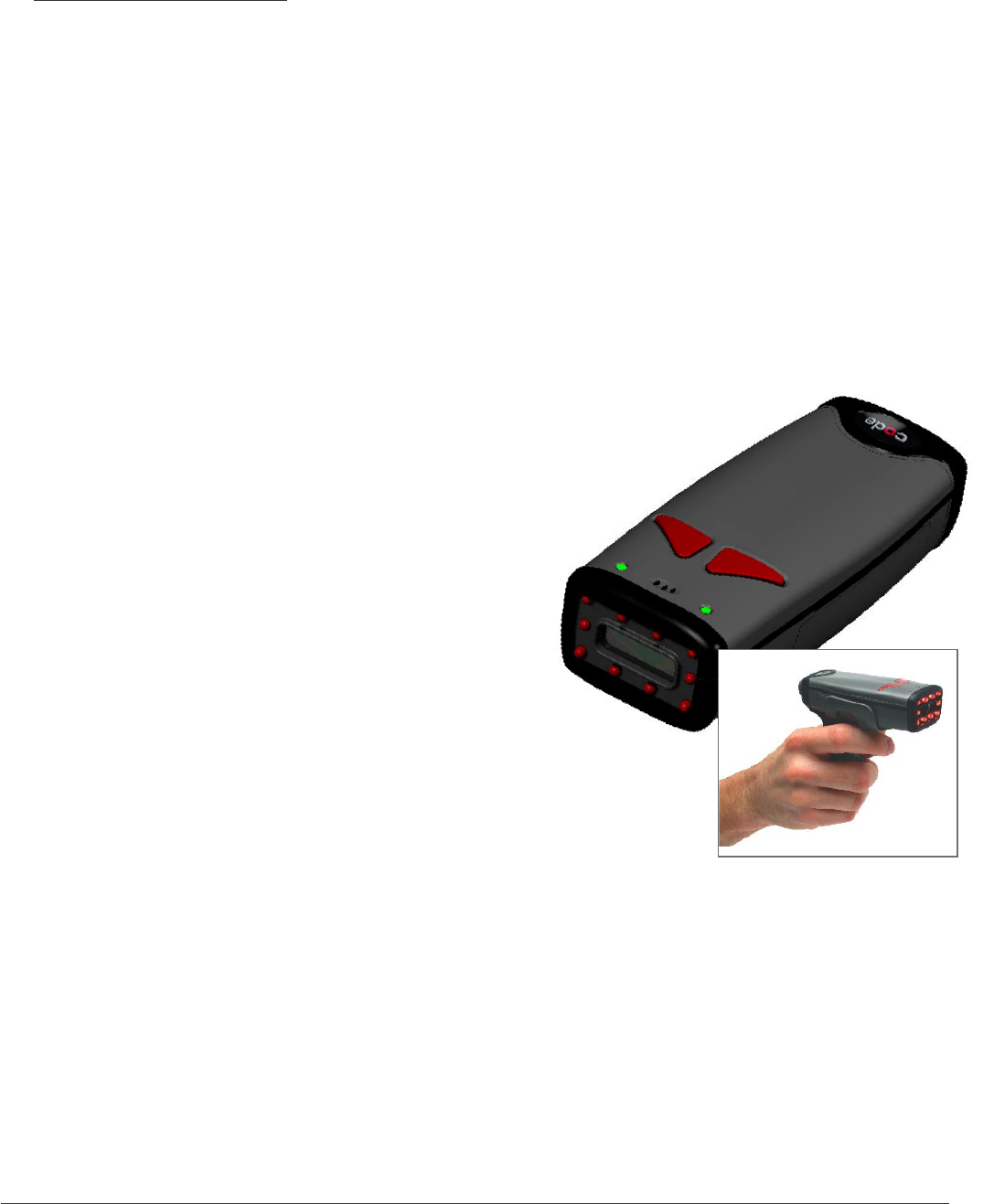
The CR2 sets a new benchmark for size and weight.
It is smaller and lighter than comparable systems
yet can withstand multiple drops to concrete. It is the
only product available in handheld, gun handle, and
presentation stand form factors with cabled, batch
and cordless versions. The cordless version utilizes
the latest Bluetooth™ class 1 radio with a 300 foot
operating range. The CR2 is rugged and lightweight
and the cordless version will operate for more than
a complete shift at the highest use rate. The CR2
performs more than 3000 reads and transmits from a
single battery charge.CR2 will automatically
discriminate between all major 2-D matrix and linear
bar code symbologies and features a timestamp
feature for logging data.
Whether you need a small, palm-held device or a traditional gun, CR2 was specically
developed so users may easily choose the device that best meets their needs. The CR2
is available in three (3) basic congurations:
• CR2 Cabled - USB or RS-232 interfaces
• CR2 Batch - Store and forward device with memory and long-life battery
• CR2 Cordless - Long life battery and Bluetooth radio
1.1 - Introduction

CR2 User’s Manual Draft_022803_AS - 2
CR2 User’s Manual Draft_022803_AS - 3
1.2 - Unpacking
Remove the imager from its packing and inspect it for damage. If the scanner was damaged
during shipping, please call Code Corpration at (801) 495-2200.
The standard CR2 unit is shipped with a USB cable interface. The unit also features a battery
blank that must be installed in the unit at all times.
Various accessories are available for the CR2. An overview of these accessories can be found
on page 9.
Please keep your packing materials. The CR2 is shipped in an approved shipping container and
should be used if you ever need to return your equipment for servicing.

CR2 User’s Manual Draft_022803_AS - 4
CR2 User’s Manual Draft_022803_AS - 5
1.3 - General Safety Information
Repairs and Adjustments
Only those individuals authorized by Code should attempt to make repairs or adjustments
to Code Reader equipment.
Power Supply
Use only the particular power supply provided for use with a specic unit when operating
Code equipment.
Accessories
Only those accessories approved by Code (page 9) should be utilized with Code equipment.
Non-compliance with any of the above may result in:
• Injury to individuals handling the equipment
• Damage to the equipment
• Voiding of the maintenance contract
Lasers
The CR2 utilizes a laser FOR TARGETING PURPOSES ONLY.
If the laser is activated, do not stare into the beam.
Lithium Ion Battery
Warning: Charge the battery with Code Corporation cables ONLY.
Do not open battery, dispose of in re, or short circuit - it may
ignite, explode, leak, or get hot causing personal injury.

CR2 User’s Manual Draft_022803_AS - 4
CR2 User’s Manual Draft_022803_AS - 5
1.4 - Warranty
Code manufactures its hardware products in accordance with industry-standard practices. Code
warrants that for a period of twelve (12) months from date of shipment, products will be free from
defects in materials and workmanship. This warranty is provided to the original owner only and is
not transferable to any third party. This warranty is subject to any and all accompanying
disclaimers, limitations and other terms of this Agreement.
It shall not apply to any product (I) which has been repaired, altered or tampered with unless done
or approved by Code, (ii) which has not been maintained in accordance with any operating or
handling instructions supplied by Code, (iii) which has been subjected to unusual physical or
electrical stress, misuse, abuse, power shortage, negligence or accident or (iv) which has been
used other than in accordance with the product operating and handling instructions. Preventive
maintenance is the responsibility of customer and is not covered under this warranty. Wear items
and accessories having a Code serial number, will carry a 90-day limited warranty. Non-serialized
items will carry a 30-day limited warranty.
Warranty Coverage and Procedure
During the warranty period, Code will repair or replace defective products returned to Code’s
service center in the US. For warranty service in North America or international, call
Code Warranty Support at 1-801-495-2200.
If warranty service is required, Code will issue a Return Material Authorization Number. Products
must be shipped in the original or comparable packaging, with shipping and insurance charges
prepaid. Code will ship the repaired or replacement product freight and insurance prepaid in North
America. Shipments from the US or other locations will be made F.O.B. Code’s manufacturing
plant. Code will use new or refurbished parts at its discretion and will own all parts removed from
repaired products. Customer will pay for the replacement product in case it does not return the
replaced product to Code within 3 days of receipt of the replacement product. The process for
return and customer’s charges will be in accordance with Code’s Exchange Policy in effect at the
time of the exchange.
Customer accepts full responsibility for its software and data including the appropriate backup
thereof. Repair or replacement of a product during warranty will not extend the original warranty
term. Code’s Customer Service organization offers an array of service plans, such as on-site,
depot, or phone support, that can be implemented to meet customer’s special operational
requirements and are available at a substantial discount during warranty period.

CR2 User’s Manual Draft_022803_AS - 6
CR2 User’s Manual Draft_022803_AS - 7
General
Except for the warranties stated above, Code disclaims all warranties, express or implied, on
products furnished hereunder, including without limitation implied warranties of merchantability
and tness for a particular purpose and noninfringement. The stated express warranties are in
lieu of all obligations or liabilities on part of Code for damages, including without limitation,
special, indirect, or consequential damages arising out of or in connection with the use or
performance of the product. Seller’s liability for damages to buyer or others (regardless of the
form of action, whether by contract, warranty, tort, malpractice, and/or otherwise) resulting from
the use of any product, shall in no way exceed the purchase price of said product. In no event
shall Code be liable for any consequential, special, indirect, incidental or punitive damages, or
for any loss of prots, revenue or data, even if Code has been advised of the possibility thereof.
1.4 - Warranty (con’t)
CR2 User’s Manual Draft_022803_AS - 6
CR2 User’s Manual Draft_022803_AS - 7
The CR2 utilizes digital camera technology to take a picture of a symbol. Once an image is
captured, the CR2 utilizes advanced decoding algorithms to extract data from the captured
image.
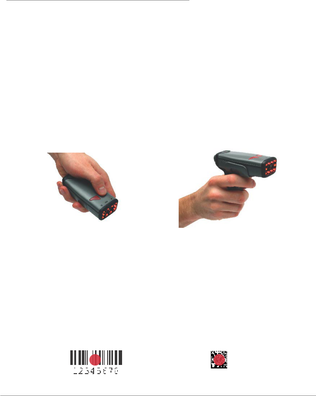
The CR2 is available as a palm-held unit or users may purchase a clip-on “gun format” handle.
The palm held unit features left and right buttons (gure 1.1). These buttons may be
programmed to perform various features (see section 4.8). The reader is shipped with the left
button and right button functioning as a decode symbol command.
The “gun format” handle features a trigger on the handle (gure 1.2). The two triggers on the top
of the unit also work when the handle is attached.
To read a symbol with the CR2:
1. The CR2 features omnidirectional decoding. Center the symbol in any orientation within
the laser dot aiming pattern (gure 1.3).
Note: The CR2 can read a symbol that is not centered however, the CR2 performs best
when a code is centered. If two (2) bar codes are with the imagers decode zone, the CR2
will decode the symbol closest to the center of the aiming dot.
1.5 - Targeting and Reading Techniques
Figure 1.1
Figure 1.3
Figure 1.2
CR2 User’s Manual Draft_022803_AS - 8
CR2 User’s Manual Draft_022803_AS - 9
1.5 - Targeting and Reading Techniques (con’t)
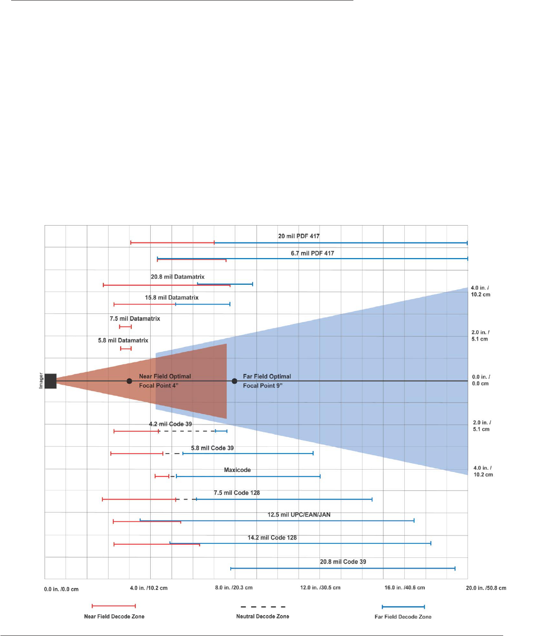
2. The CR2 was developed to decode both very small 2-dimensional symbols and larger
1-dimensional symbols. The unit features two imagers to create an innovative dual decode
zone. The CR2 features a high speed processor and DECODES BOTH ZONES
SIMULTANEOUSLY. The unit has one imager focused on a near-eld for smaller codes
(optimal focal point is 4 inches) and one imager focused on a far-eld for larger codes
(optimal focal point 9 inches). To read smaller symbols move the CR2 closer to the
symbol. To read larger symbols move the unit farther away from the symbol (see gure 1.4).
The entire CR2 decode zone varies between two (2”) and twenty (20+”) or more inches.
3. Hold the Code Reader still - DO NOT SWIPE OR MOVE THE READER.
Press the trigger until the CR2 beeps, indicating the bar code has been successfully decoded.
Figure 1.4
CR2 User’s Manual Draft_022803_AS - 8
CR2 User’s Manual Draft_022803_AS - 9
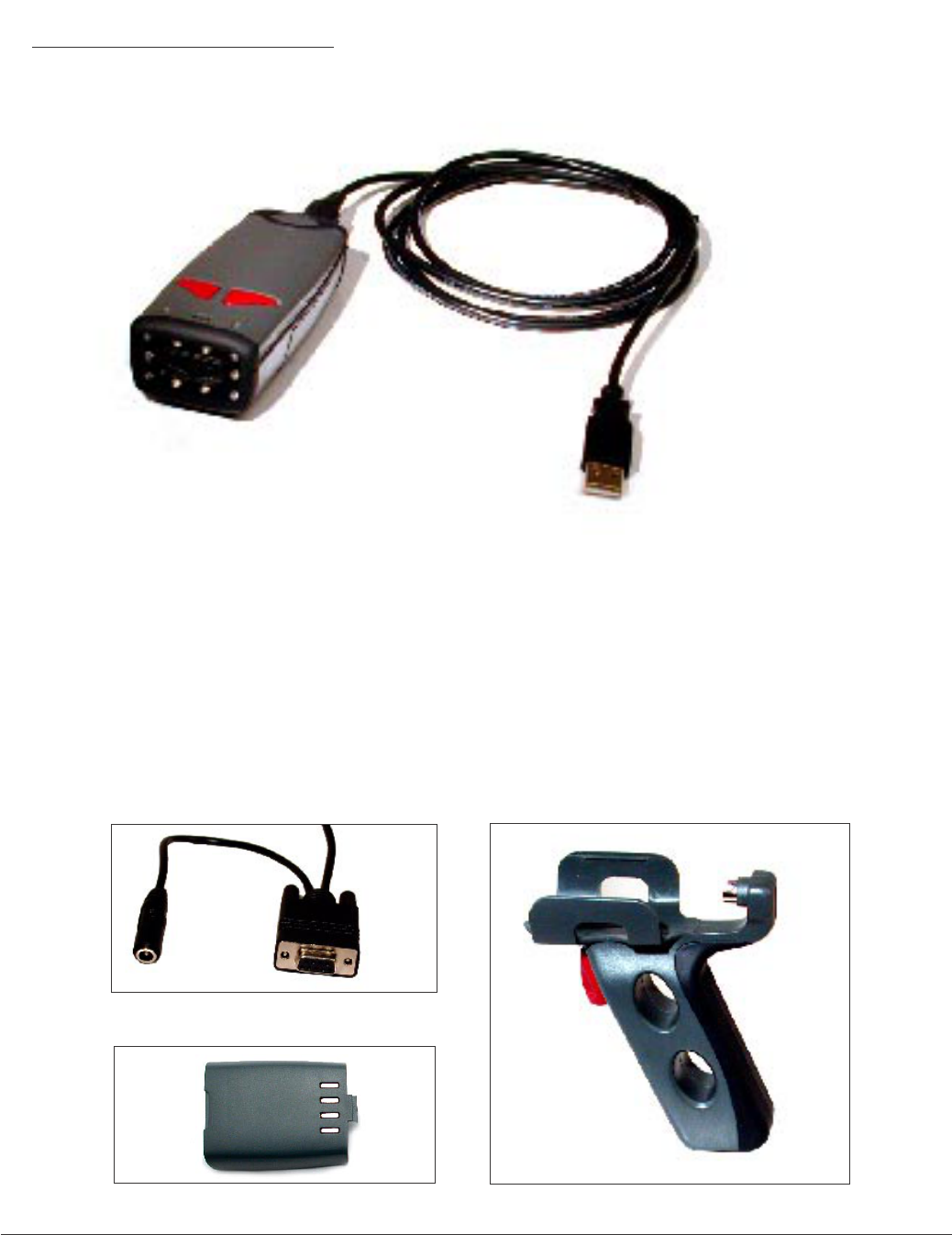
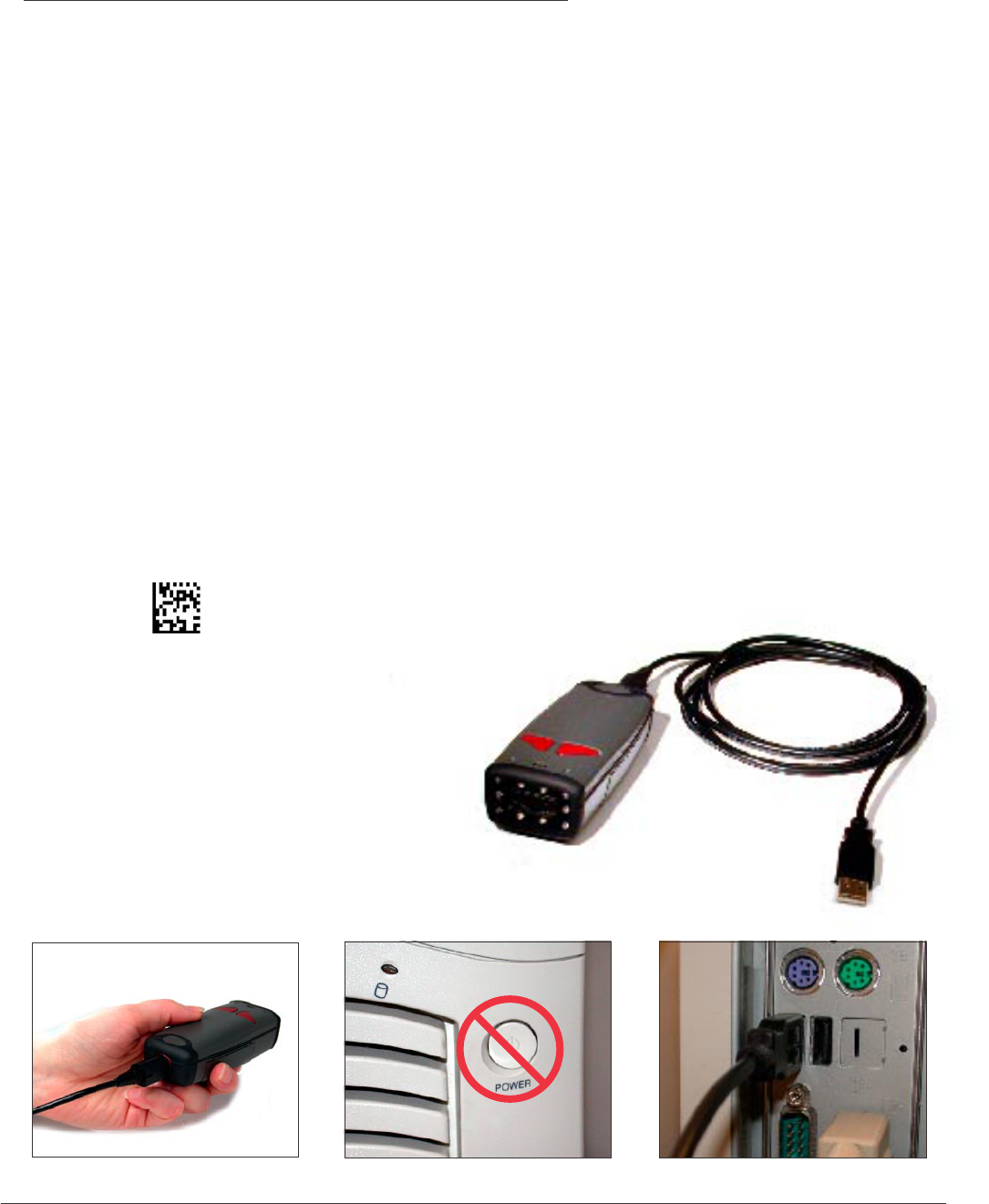
The standard CR2 unit is a palm-held device with a USB cable interface (gure 1.5).
Optional Accessories
The following accessories are also available by contacting a Code representative:
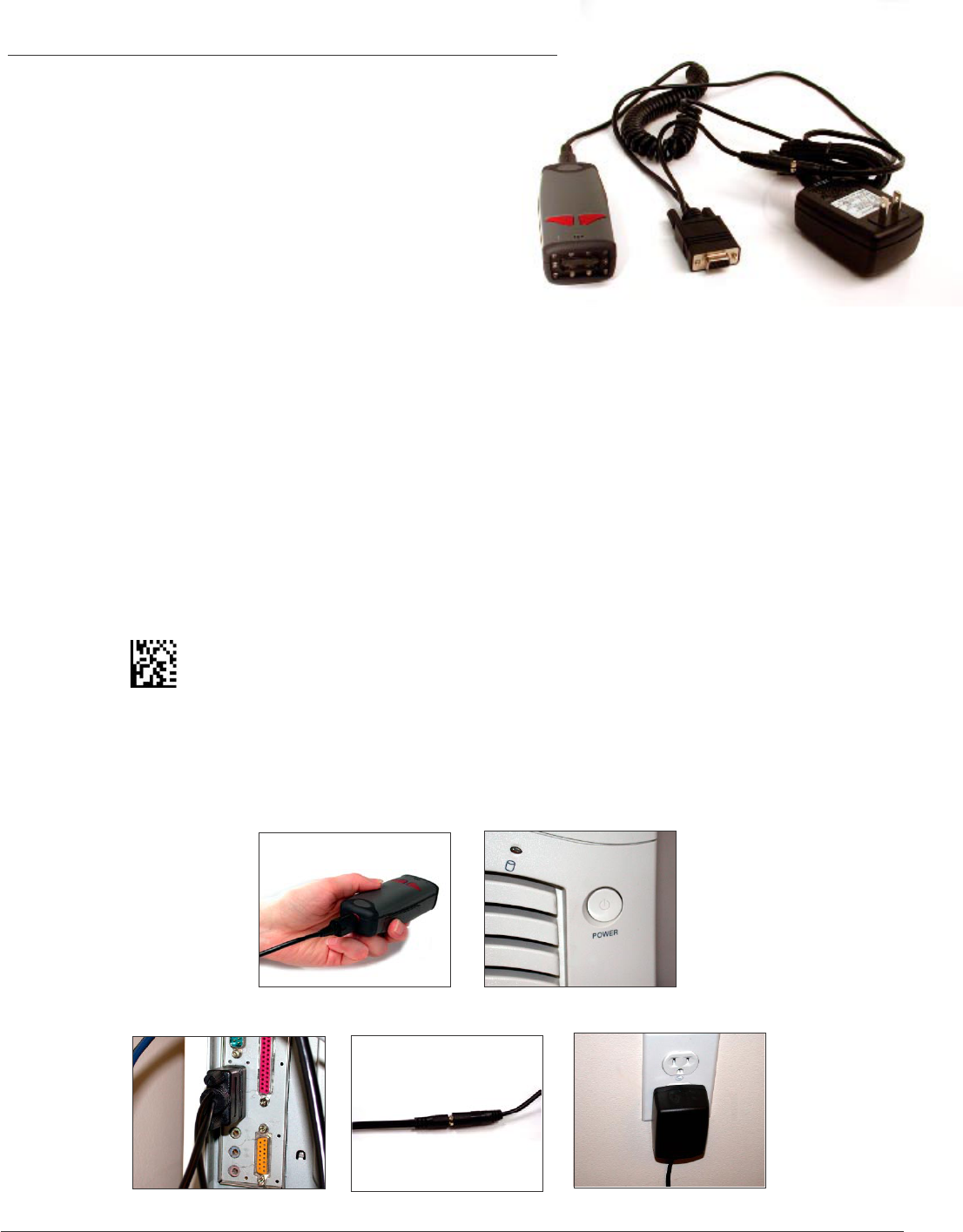
• RS-232 interface cables (Figure 1.6)
• 1300 mA or 1800 mA Long-life Lithium-Ion battery (Figure 1.7)
•. Clip-on pistol grip handle (Figure 1.8)
• Class 1 Bluetooth radio (300 foot operating range if connected with
another Class 1 device)
1.6 - CR2 Accessories
Figure 1.5 CR2 with USB Cable Interface
Figure 1.6 RS-232 Cable Interface
Figure 1.8 Clip-on Pistol Grip Handle
Figure 1.7 Long-life Battery

CR2 User’s Manual Draft_022803_AS - 10
CR2 User’s Manual Draft_022803_AS - 11
Chapter 2 - Getting Started

CR2 User’s Manual Draft_022803_AS - 10
CR2 User’s Manual Draft_022803_AS - 11
2.1 - Minimum Requirements
Operating Systems: Windows © - 98 (version 2), ME, 2000, XP
Interfaces: USB or RS-232 / Serial
Bluetooth: CR2 only supports Bluettoth serial prole
CR2 User’s Manual Draft_022803_AS - 12
CR2 User’s Manual Draft_022803_AS - 13
2.2 - Installation Guide - USB Interface
To connect the CR2 to your host computer via USB interface:
1. Make sure the USB cable is sufciently attached to your CR2 unit (gure 2.1).
2. You DO NOT need to power off your host computer (gure 2.2). The CR2 with
USB interface can be plugged into any host while the computer is powered up.
3. Connect the USB interface cable to the host (gure 2.3). If you are unsure of
the proper location to connect the USB cable please consult the manual of
your host computer.
4. The USB interface does not require additional power supply. If you are using
the 1300 mA or 1800 mA battery for batch mode, the CR2 will automatically recharge
the battery whenever the unit is a attached to a host that is powered up.
5. The CR2 will power on automatically.
6. Scan the following code to set reader into USB communication mode.
Note: You may also scan the code
on page 45 of the User’s Manual
7. Your CR2 unit should
be ready for use.
Open the application
you wish to send data
and begin scanning.
Figure 2.1 Figure 2.2 Figure 2.3
CR2 User’s Manual Draft_022803_AS - 12
CR2 User’s Manual Draft_022803_AS - 13
2.2 - Installation Guide - RS-232 Interface
To connect the CR2 to your host computer via RS-232 interface:
1. Make sure the RS-232 cable is sufciently
attached to your CR2 unit (gure 2.4).
2. Power off your host computer (gure 2.5).
3. Connect the RS-232 interface cable to your
host computer (gure 2.6). If you are unsure
of the proper location to connect the RS-232
cable please consult the manual of your host computer.
4. The RS-232 interface does require additional power. The RS-232 interface should have
come with a power supply. Plug the power supply adapter into the RS-232 interface cable
(gure 2.7) and then plug the power adapter into a wall socket (gure 2.8). If you are using
the 1300 mA or 1800 mA battery for batch mode, the CR2 will recharge the battery
whenever the unit is a attached to a RS-232 cable that is plugged into a wall socket.
5. Power up the host.
6. The CR2 will power on automatically.
7. Scan the following code to set reader into RS-232 / Serial communication mode.
Note: You may also scan the code on page 47 of the CR2 User’s Manual.
8. Your CR2 unit should be ready for use. Open the application you wish to send data
and begin scanning.
Figure 2.6 Figure 2.7 Figure 2.8
Figure 2.4 Figure 2.5

CR2 User’s Manual Draft_022803_AS - 14
CR2 User’s Manual Draft_022803_AS - 15
2.2 - Installation Guide - Batch Interface
The CR2 unit features a batch mode for applications requiring a portable reader. Batch mode
allows a user to store scanned data to the reader’s non-volatile memory. The user may transfer
the data to a host computer when needed. To utilize batch functionality you will need to
purchase the 1300 mA or 1800 mA Lithium Ion battery from a Code representative.
How Batch Mode Works
The CR2 unit will automatically detect when the USB cable is detached or the
Bluetooth® radio is out of range and will switch into batch mode. CR2 units featuring RS-232
interfaces have to be programmed to enter batch mode by scanning a code (see section 4.6).
When the reader is reconnected to your host computer or when the Bluetooth Radio is back in
range and the user scans another code or the specic transfer data code, (Users may also
program a button in section 4.6 to transfer data) the reader will transfer scanned data. Once
transferred, the scanned data is immediately erased from the readers memory.
Batch Mode Feedback
After a successful scan in batch mode the unit will beep once and the battery LED will ash
amber and the memory LED will ash either green, red or amber depending on memory level.
For more information on CR2 feedback see section 2.6.
Note: The CR2 dedicated batch memory is a minimum of 1MB. To determine the number of
reads that may be stored, divide the average bytes of a scan into the total minimum memory.
Figure 2.9

CR2 User’s Manual Draft_022803_AS - 14
CR2 User’s Manual Draft_022803_AS - 15
Batch Programming Modes
The CR2 can be programmed to operate in two (2) other operating modes:
1. Manual Erase Mode - In manual erase mode, when the reader Is reconnected to your
host computer or when the Bluetooth Radio is back in range and the user scans
another code or the specic transfer data code (Users may also program a button in
section 4.6 to transfer data) the reader will transfer scanned data. However, once the
readers memory has been transferred, the user must scan a specic code to erase the
units memory (see section 4.6). If you enter batch mode again without erasing the
data, the new scanned data will be added to the existing data.
Note: Once the unit is plugged back into a cable or enters within radio range, any
data scanned WILL NOT be saved to the non-volatile memory. The only data that
will be saved is the data scanned while in batch mode.
2. Send and Store Mode - In send and store mode, the reader will automatically try to
transfer scanned data everytime a new code is scanned. In parallel, the unit will also
store a copy of all scanned data on the unit’s non-volatile memory. If the readers
memory has been transferred to a host computer all scanned data will still reside on
the units memory until the user scans a specic code to erase the memory.
Note: All scanned data WILL be saved to the non-volatile memory even if a cable
is attached or the radio is within range.
2.2 - Installation Guide - Batch Interface (con’t)

CR2 User’s Manual Draft_022803_AS - 16
CR2 User’s Manual Draft_022803_AS - 17
2.2 - Installation Guide - Cordless Interface
Overview
The CR2 features an add-on Bluetooth® wireless radio. The radio allows for point to point wireless
communication with other Bluetooth devices. The Bluetooth radio replaces the cord, allowing for
300 feet or more of operating range if you are connecting with another Class 1 device.
A typical set-up to link the CR2 unit to a desktop or a laptop computer would require purchasing an
attachable USB Bluetooth radio. For more detailed instructions on connecting with approved Bluetooth
enabled devices please see Appendix A.
The CR2 stores a memory of 256 devices it has established a connection with. Code makes it simple
to reconnect with these devices. If you wish set up a network of readers or devices please see
Appendix B “Setting up a Network of Bluetooth Devices”.
The following guide will give you general instructions on connecting your CR2 to a desktop or laptop
computer with a Bluetooth Radio antennae. Each brand of attachable radio will have unique connection
manager software however, the process of getting connected is very similar. You should be able to
follow these general steps and establish a connection.
If you have questions with your connection please call Code Technical Support
at 1-801-495-2200.
Creating a Bonded Relationship
When you create a bonded relationship you are establishing that your devices know each other
and will connect directly after the rst encounter. Bonding is also often refferred to as pairing. To
create a bonded relationship with another Bluetooth device you must get the Bluetooth Radio PIN #
of your CR2. The Bluetooth PIN # is the same as your units serial #. The serial number is located
underneath the battery on the CR2 specication sticker or you can scan the Reader ID code on
page 52 of the CR2 User’s Manual. THE BLUETOOTH PIN # FOR BETA UNITS IS: 12345678.
1. To minimize connection interference, turn off all other Bluetooth
devices in the area.
2. Open the connection manager software on the device you wish to
connect to and select the following settings:
• Bluetooth radio is enabled
• Low Security - Discoverable by all devices
• Enable serial port prole
CR2 User’s Manual Draft_022803_AS - 16
CR2 User’s Manual Draft_022803_AS - 17
2.2 - Installation Guide - Cordless Interface (con’t)
Note: Your CR2 unit will function as the master (head device) in a group of
enabled devices. Other devices are referred to as slave devices. It is very important
to understand that the CR2 will have precedence over other devices. The CR2 units
are shipped with the authentication and encryption security feature disabled. When
making initial contact with another device, you must have the authentication and
encryption functionality disabled on the slave device you are connecting to.
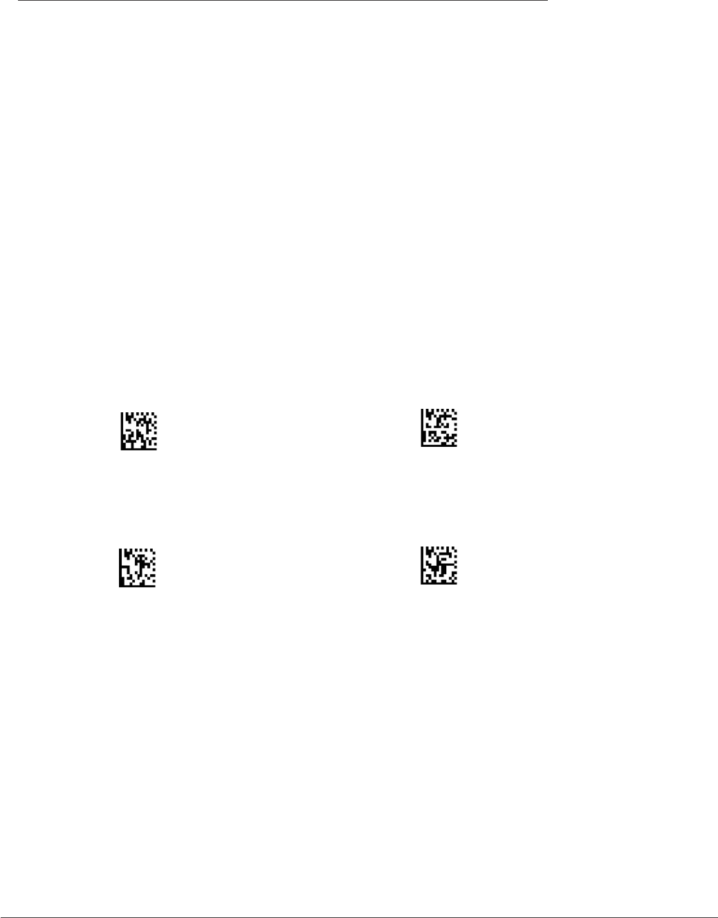
3. Scan the Reset code then scan the Enable Radio code below:
Reset to Factory Defaults Enable Radio (RF)
4. With your CR2, scan the “pairing” command code, then scan the “inquire
and connect” command code. The CR2 will search and automatically request
to bond with activated devices.
Enable Pairing Inquire and Connect
5. When the desired slave device prompts for a pin, type in your CR2 Bluetooth PIN #.
6. The CR2 should now be added to the slave devices bonded list.
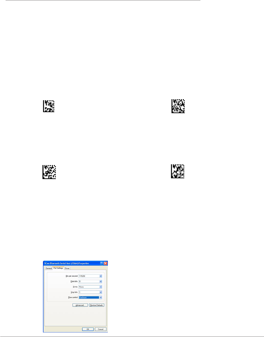
7. Once you have established a connection, you must make sure the device is set to
a serial port prole. On your host, right click the My Computer icon on your desktop.
Open Properties. Under the Hardware tab select Device Manager button. Click on the
appropriate device and set to the following settings:

CR2 User’s Manual Draft_022803_AS - 18
CR2 User’s Manual Draft_022803_AS - 19
8. You must also set up your application software to a serial port prole.
9. If encryption is desired, disconnect then scan “enable encryption” then scan
“inquire and connect”. Be prepared to type the PIN again.
Disconnect Enable Encryption
Note: Code strongly suggests that each slave device be enabled to connect only
with devices in its bonded/paired list. This action will preclude unwanted outside
connections, including hostile connection attempts.
.
You may have to repeat the process. Reasons why connection may not occur are:
• Device is out of range or the Bluetooth radios is turned off
• The desired device is already connected to another device
• CR2 is not in bonded list
• CR2 has incorrect Bluetooth address or link key, or both associated with the
desired device list number
Transferring Data
The application software on the desired device must be running. As codes are read, they will
automatically transmit to the application.
Disconnecting
Disconnection is commanded by CR2 by reading the disconnect code below. The CR2
will not appear disconnected in the slave Bluetooth connection manager for 10 – 15
seconds after the command is issued.
Disconnect
2.2 - Installation Guide - Cordless Interface (con’t)
CR2 User’s Manual Draft_022803_AS - 18
CR2 User’s Manual Draft_022803_AS - 19
Reconnecting to a Device
You may easily reconnect with up to 256 slave devices the CR2 has created a bonded relationship
with. these devices by utilizing our label template at:
www.codecorp.com/products/downloads/bluetoothlabels.
Note: The template will not be available until 3/1/03. To test this feature follow the instructions below:
1. While connected to a the desired slave device, scan the “Save to 001” code
located below.
2. Disconnect devices. Scan the “Connect to 001” code. Now everytime you scan
the “Connect to 001” code, the CR2 you will instantly bond with the device
Save to 001 Connect to 001
Save to 002 Connect to 002
2.2 - Installation Guide - Cordless Interface (con’t)
CR2 User’s Manual Draft_022803_AS - 20
CR2 User’s Manual Draft_022803_AS - 21
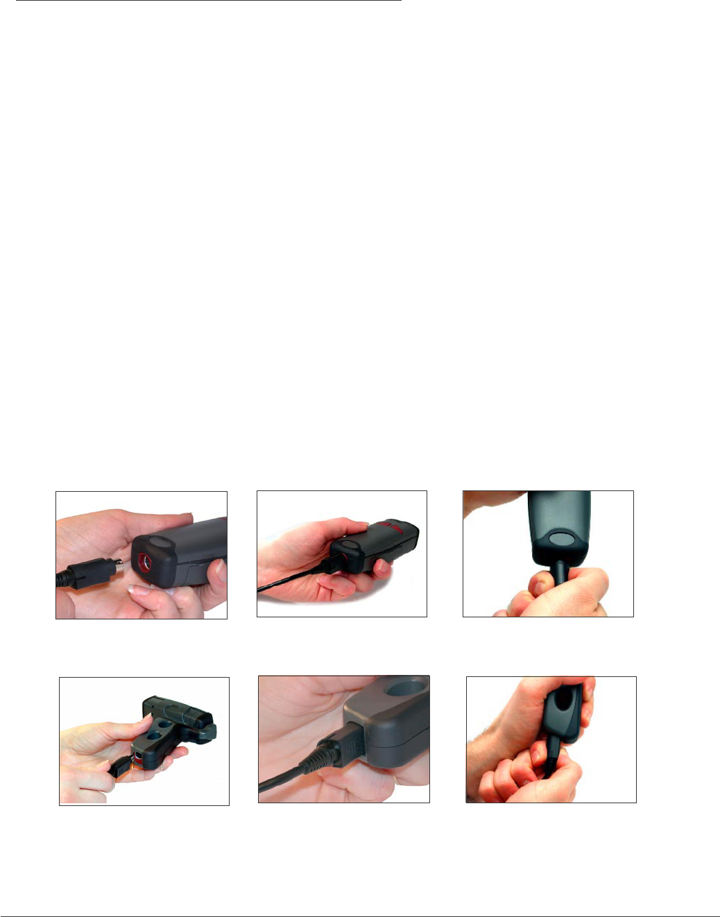
Attaching and Switching Cables
The CR2 is available with USB (standard) and RS-232 cables. All of the cables are connected to the
CR2 with a 8-pin DIN connector. Different cables may be required for different hosts.
Palm Held CR2
To install a cable on the standard palm-held unit, correctly line up the 8-pin DIN connector (gure 2.10)
into back end of the unit. The arrows on the connector should be facing down. When they are lined up,
rmly push the cable in (gure 2.11). To unattach, you must pinch the plastic on the 8-pin DIN and pull
back to disengage the connector (gure 2.12).
CR2 with Attachable Handle
If you purchased the attachable handle accessory (see section 2.3 for handle attaching instructions),
the 8-pin DIN connection is at the botton of the handle. Insert 8-Pin connector (gure 2.13) and rmly
push cable into the handle (gure 2.14). To unattach, you must pinch the plastic on the 8-pin DIN and
pull back to disengage the connector (gure 2.15).
2.3 - Attaching and Switching Cables
Figure 2.10 Figure 2.11
Figure 2.13 Figure 2.14
Figure 2.12
Figure 2.15

CR2 User’s Manual Draft_022803_AS - 20
CR2 User’s Manual Draft_022803_AS - 21
2.4 - Attaching Handle
Attaching the Handle
To attach the handle, please follow the following steps.
1. Place the CR2 in the cradle of the handle and slide the unit back (gure 2.16).
Be careful not to place ngerprints on the front glass when attaching handle.
2. Once the 8-pin DIN connector of the handle begins to enter the opening in
the back of the unit, rmly press the unit back until the unit is ush against the
handle (gure 2.17).
Figure 2.16
Figure 2.17
CR2 User’s Manual Draft_022803_AS - 22
CR2 User’s Manual Draft_022803_AS - 23
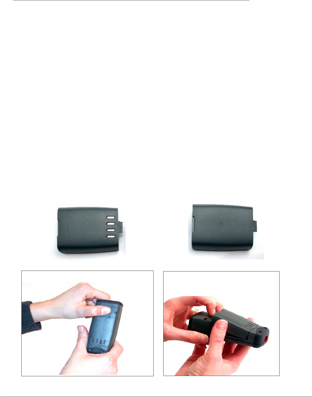
2.5 - CR2 Lithium Ion Battery and CR2 Battery Blank
CR2 Battery Blank
All cabled CR2 units feature a battery blank. THE BATTERY BLANK NEEDS TO BE
ATTACHED AT ALL TIME WHEN USING THE CR2. Installing the battery blank is identical to
installing the battery. Please follow the instructions below.
Attaching and Detaching the Lithium Ion Battery
The CR2 is available with a 1300 mA or 1800 mA Lithium Ion battery. If you wish to purchase,
contact a Code representative. To install battery or battery blank in cradle or to detach battery
from unit, push the locking mechanism up toward the front of the scanner and insert or detach
battery (gures 2.18 & 2.19).
Charging the Lithium Ion Battery
The battery automatically charges everytime a cable inteface is attached to the unit and
the host is powered up
Note: The RS-232 interface power adapter must be plugged into a wall socket for the unit to
charge.
Figure 2.18 Figure 2.19
Battery Battery Blank
CR2 User’s Manual Draft_022803_AS - 22
CR2 User’s Manual Draft_022803_AS - 23
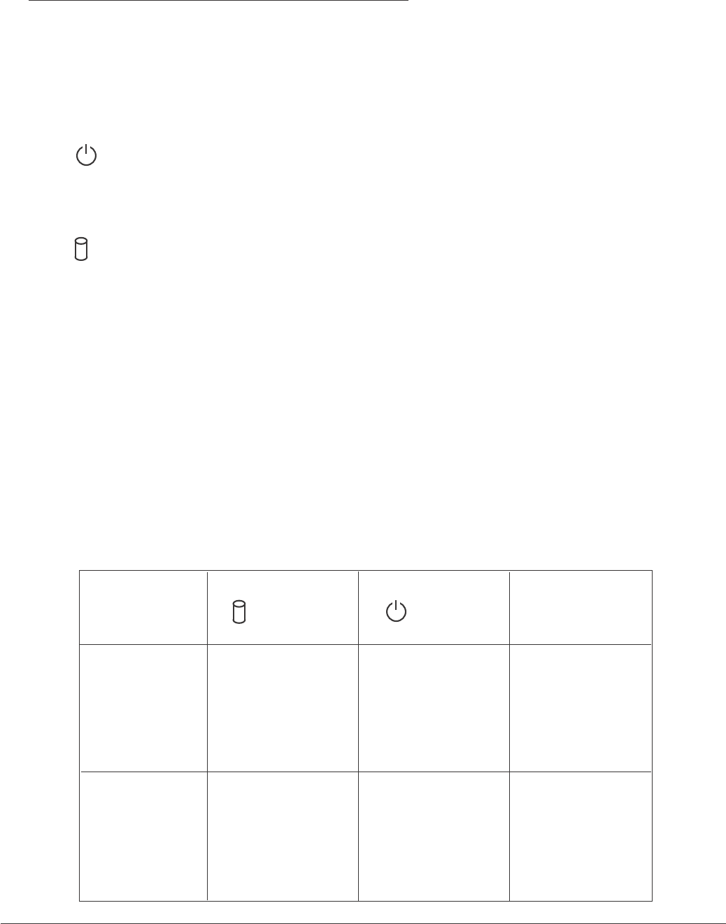
2.6 - CR2 Feedback Denition Guide
The CR2 features two (2) LED’s on the front of the unit. These LED’s give a user feedback on
the various functionality of the unit. Each LED has a small icon underneath that represent the
following:
Battery Power Icon
Memory Icon
Each LED can show three (3) colors; Green, Amber or Red. The colors will vary depending on
the message the unit is sending.
• Green = 50% - 100% capacity of Battery or Memory
• Amber = 20% - 50% capacity of Battery or Memory
• Red = 0% - 20% capacity of Battery or Memory
The CR2 also emits beeps for feedback. Please follow the table below to better understand
your unit’s feedback.
CR2
Successfully
Powers Up
Attempting to
Decode
Sound
1 Beep
Battery
LED
Flash either
Green, Amber
or Red
None
Memory
LED
Flash battery
status either
Green, Amber
or Red
None None

CR2 User’s Manual Draft_022803_AS - 24
CR2 User’s Manual Draft_022803_AS - 25
2.6 - CR2 Feedback Denition Guide (con’t)
Successful
Decode in
Batch mode
Successful
Decode unable
to transfer data
in Batch mode
Conguration
Code
Successfully
Decoded
Batch Mode
memory full
2 Beeps
1 Beep
1 Beep
4 Beeps
Successful
Decode and
Data Transfer
via cable
1 Beep
Sound
None
Flash Amber
Flash Green
then Red
Flash either
Green, Amber or
Red
Flash Green
Battery
LED
Flash either
Green, Amber
or Red
Flash either
Green, Amber
or Red
Flash either
Green, Amber
or Red
Red
Flash battery
status either
Green, Amber or
Red
Memory
LED

CR2 User’s Manual Draft_022803_AS - 24
CR2 User’s Manual Draft_022803_AS - 25
Chapter 3 - Symbology Programming

CR2 User’s Manual Draft_022803_AS - 26
CR2 User’s Manual Draft_022803_AS - 27
3.1 - Introduction
The following chapter will allow a user to change the symbology settings on the Code Reader.
To reset the unit to factory defaults or to save the current settings please scan one of the codes
below:
Save Settings
Note: If you do not save your settings and the CR2 loses power you will lose your
settings.
Reset to Factory Defaults
CR2 User’s Manual Draft_022803_AS - 26
CR2 User’s Manual Draft_022803_AS - 27
3.2 - Aztec Symbology
Scan the following codes to enable/disable Aztec symbology settings:
Aztec On Aztec Off
Aztec Inverse On Aztec Inverse Off Aztec Both
CR2 User’s Manual Draft_022803_AS - 28
CR2 User’s Manual Draft_022803_AS - 29
3.3 - Codabar Symbology
Scan the following codes to enable/disable Codabar symbology settings:
Codabar On Codabar Off
Check Checksum Don’t Check Checksum

CR2 User’s Manual Draft_022803_AS - 28
CR2 User’s Manual Draft_022803_AS - 29
3.4 - Code 128 Symbology
Scan the following codes to enable/disable Code 128 symbology settings:
Code 128 On Code 128 Off

CR2 User’s Manual Draft_022803_AS - 30
CR2 User’s Manual Draft_022803_AS - 31
3.5 - Code 93 Symbology
Scan the following codes to enable/disable Code 93 symbology settings:
Code 93 On Code 93 Off
CR2 User’s Manual Draft_022803_AS - 30
CR2 User’s Manual Draft_022803_AS - 31
3.6 - Code 39 Symbology
Scan the following codes to enable/disable Code 39 symbology settings:
Code 39 On Code 39 Off
Check Checksum Don’t Check Checksum
Check Checksum and Stip From Result
Code 39 Full ASCI On Code 39 Full ASCI Off

CR2 User’s Manual Draft_022803_AS - 32
CR2 User’s Manual Draft_022803_AS - 33
3.7 - Composite Symbologies
Scan the following codes to enable/disable Composite symbology settings:
Composite On Composite Off
CR2 User’s Manual Draft_022803_AS - 32
CR2 User’s Manual Draft_022803_AS - 33
3.8 - Data Matrix Symbology
Scan the following codes to enable/disable Data Matrix symbology settings:
Data Matrix On Data Matrix Off
Data Matrix Inverse On Data Matrix Inverse Off Data Matrix Both
Data Matrix Rectangle On Data Matrix Rectangle Off

CR2 User’s Manual Draft_022803_AS - 34
CR2 User’s Manual Draft_022803_AS - 35
3.9 - GoCode Symbology
Scan the following codes to enable/disable GoCode symbology settings:
GoCode On GoCode Off

CR2 User’s Manual Draft_022803_AS - 34
CR2 User’s Manual Draft_022803_AS - 35
3.10 - Interleaved 2 of 5 Symbology
Scan the following codes to enable/disable Interleaved 2 of 5 symbology settings:
Interleaved 2 of 5 On Interleaved 2 of 5 Off

CR2 User’s Manual Draft_022803_AS - 36
CR2 User’s Manual Draft_022803_AS - 37
3.11 - Maxicode Symbology
Scan the following codes to enable/disable Maxicode symbology settings:
Maxicode On Maxicode Off

CR2 User’s Manual Draft_022803_AS - 36
CR2 User’s Manual Draft_022803_AS - 37
3.12 - MSI Plessy Symbology
Scan the following codes to enable/disable MSI Plessy symbology settings:
MSI Plessy On MSI Plessy Off

CR2 User’s Manual Draft_022803_AS - 38
CR2 User’s Manual Draft_022803_AS - 39
3.13 - PDF 417 Symbology
Scan the following codes to enable/disable PDF 417 symbology settings:
PDF417 On PDF417 Off

CR2 User’s Manual Draft_022803_AS - 38
CR2 User’s Manual Draft_022803_AS - 39
3.14 - Micro PDF 417 Symbology
Scan the following codes to enable/disable micro PDF 417 symbology settings:
MicroPDF417 On MicroPDF417 Off
CR2 User’s Manual Draft_022803_AS - 40
CR2 User’s Manual Draft_022803_AS - 41
3.15 - Postal Symbologies
Scan the following codes to enable the appropriate Postal symbology:
Note: If you wish to change which Postal code is activated, you MUST scan the disable
all postal codes symbol and then scan your desired symbology.
Australian Post On
Japan Post On
KIX On
Planet On
Postnet On
Postnet and Planet On
Royal Mail
DISABLE ALL POSTAL CODES
CR2 User’s Manual Draft_022803_AS - 40
CR2 User’s Manual Draft_022803_AS - 41
3.16 - QR Code Symbology
Scan the following codes to enable/disable QR Code symbology settings:
QR Code On QR Code Off
QR Code Inverse On QR Code Inverse Off QR Code Both
Check Checksum Don’t Check Checksum

CR2 User’s Manual Draft_022803_AS - 42
CR2 User’s Manual Draft_022803_AS - 43
3.17 - RSS Symbology
Scan the following codes to enable/disable RSS symbology settings:
RSS On RSS Off
CR2 User’s Manual Draft_022803_AS - 42
CR2 User’s Manual Draft_022803_AS - 43
3.18 - UPC/EAN/JAN
Scan the following codes to enable/disable UPC/EAN/JAN symbology settings:
UPC On UPC Off
UPC Extension On UPC Extension Off
UPC Supplemental On UPC Supplemental Off

CR2 User’s Manual Draft_022803_AS - 44
CR2 User’s Manual Draft_022803_AS - 45
Chapter 4 - CR2 Advanced Programming

CR2 User’s Manual Draft_022803_AS - 44
CR2 User’s Manual Draft_022803_AS - 45
4.1 - Reader Communication Settings - USB Interface
Scan the following codes to set your reader to the appropriate USB
communication setting:
USB Keyboard (Default)
USB Native
USB IBM

CR2 User’s Manual Draft_022803_AS - 46
CR2 User’s Manual Draft_022803_AS - 47
4.1 - Reader Communication Settings - RF Interface
Scan the following codes to set your reader to RF communication setting:
RF Communication

CR2 User’s Manual Draft_022803_AS - 46
CR2 User’s Manual Draft_022803_AS - 47
4.1 - Reader Communication Settings - RS-232 Interface
Scan the following code to set your reader to RS-232/serial communication
setting:
RS-232 / Serial

CR2 User’s Manual Draft_022803_AS - 48
CR2 User’s Manual Draft_022803_AS - 49
4.2 - RS-232 Interface Settings - Set Data Bits
Scan the following codes to set the appropriate data bit:
7 Data Bits
8 Data Bits (Default)

CR2 User’s Manual Draft_022803_AS - 48
CR2 User’s Manual Draft_022803_AS - 49
4.2 - RS-232 Interface Settings - Set Stop Bit Data
Scan the following codes to set the appropriate stop bit data:
1 Stop Bit
2 Stop Bits
CR2 User’s Manual Draft_022803_AS - 50
CR2 User’s Manual Draft_022803_AS - 51
1200
2400
4800
9600
4.2 - RS-232 Interface Settings - Set Baud Rate
19200
38400
57600 (Default)
Scan the following codes to set the appropriate baud rate:

CR2 User’s Manual Draft_022803_AS - 50
CR2 User’s Manual Draft_022803_AS - 51
4.2 - RS-232 Interface Settings - Set Parity
Scan the following codes to set parity:
Even
Odd
None (Default)

CR2 User’s Manual Draft_022803_AS - 52
CR2 User’s Manual Draft_022803_AS - 53
4.3 - Set Prex / Sufx
Scan the following codes to set parity:
These codes will only work if CR2 unit is set to RS-232 / serial
communication mode (page 44).
Sufx - Carriage Return Line Feed ON *
Sufx - Carriage Return Line Feed OFF *
* These codes are subject to change for later versions of rmware.
CR2 User’s Manual Draft_022803_AS - 52
CR2 User’s Manual Draft_022803_AS - 53
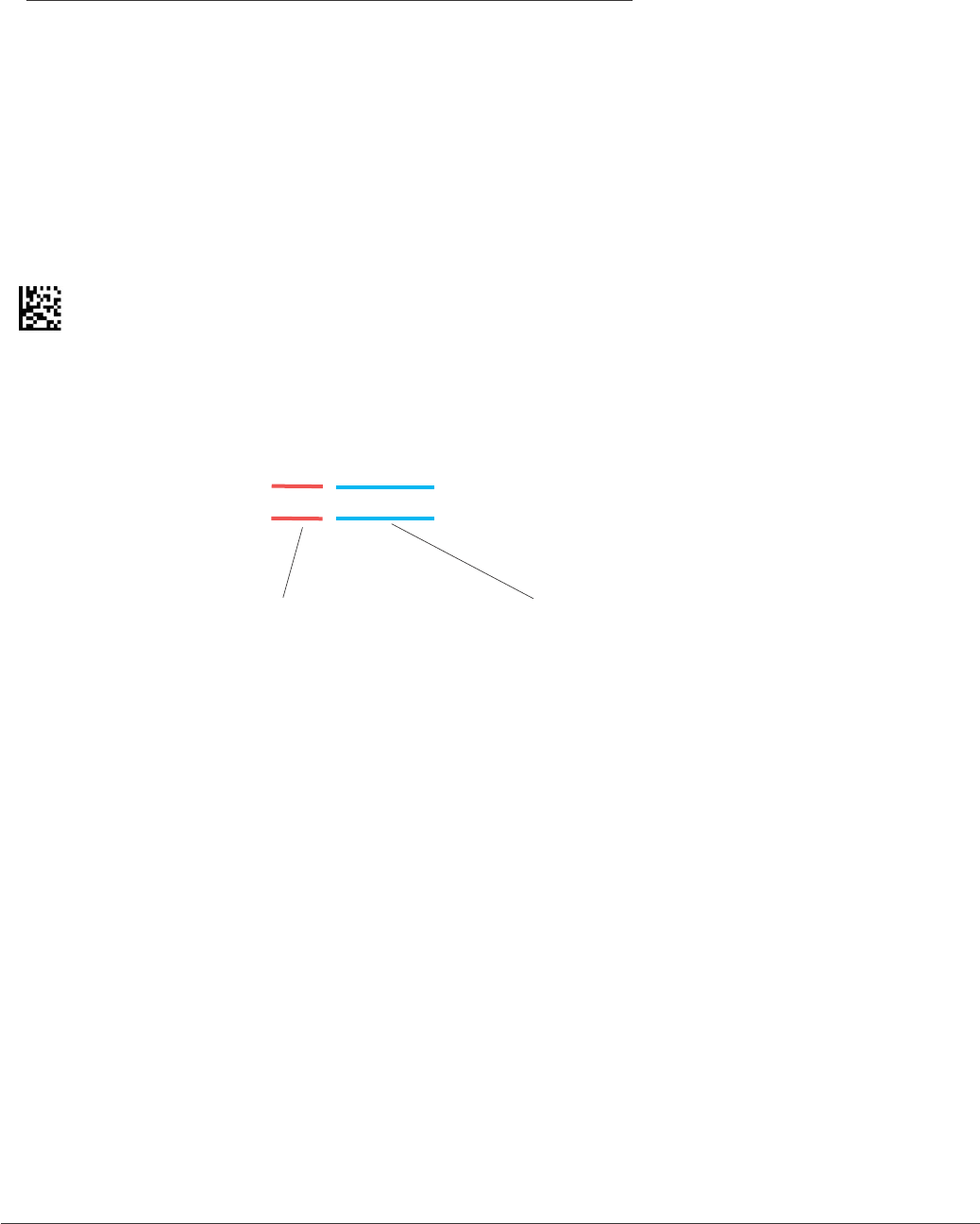
To nd out the Reader ID and rmware version, open a text editor program
(i.e. Notepad, Microsoft Word...) and read the following code:
Note: For units with a Bluetooth Radio, the Reader ID is also your Bluetooth
Radio PIN #.
Reader ID and Firmware
You will get a text string with your rmware version and Code Reader ID number
(see below):
03AB10100101__01681540001000
4.4 - Get Reader ID and Firmware Version
Firmware Version Code Reader ID #

CR2 User’s Manual Draft_022803_AS - 54
CR2 User’s Manual Draft_022803_AS - 55
CR2 has a time stamp feature for logging data (The time stamp is defaulted off in
shipped units). If you enable the time stamp feature, everytime the CR2 is powered
off or rebooted, the timer will stop.
A 8-digit number represents the time stamp. The format is ddhhmmss (dayday/
hourhour/minuteminute/secondsseconds). Scan the following codes to turn the
time-stamp on/off:
On
Off
4.5 - Time Stamp Settings
CR2 User’s Manual Draft_022803_AS - 54
CR2 User’s Manual Draft_022803_AS - 55
Scan the following codes to set the appropriate batch functionality:
Transfer Scanned Data from Memory
Enable Send and Store
Disable Send and Store
Enable Manual Erase
Disable Manual Erase
4.6 - Batch Mode Settings
Delete Scanned Data Memory
Enable RS-232 Batch Mode
Enable RS-232 Cabled Mode

CR2 User’s Manual Draft_022803_AS - 56
CR2 User’s Manual Draft_022803_AS - 57
4.7 - Bluetooth Radio Settings
Scan the following codes to set the left button functionality:
Enable RF
Inquire and Connect
Pairing Enabled
Enable Encryption and Authentication
Disconnect
CR2 User’s Manual Draft_022803_AS - 56
CR2 User’s Manual Draft_022803_AS - 57
Scan the following codes to set the left button functionality:
Erase Image
Keep Awake
No Function
Read Codes in Both Zones (Default)
Read Code with Far-Field Imager ONLY
Read Code with Near-Field Imager ONLY
4.8 - Left Button Programming
Read Strip Code
Take Picture
Set Laser Targeting
Upload Stored Data
CR2 User’s Manual Draft_022803_AS - 58
CR2 User’s Manual Draft_022803_AS - 59
4.8 - Right Button Programming
Scan the following codes to set the right button functionality:
Erase Image
Keep Awake
No Function
Read Codes in Both Zones (Default)
Read Code with Far-Field Imager ONLY
Read Code with Near-Field Imager ONLY
Read Strip Code
Take Picture
Set Laser Targeting
Upload Stored Data
CR2 User’s Manual Draft_022803_AS - 58
CR2 User’s Manual Draft_022803_AS - 59
4.8 - Handle Button Programming
Scan the following codes to set the handle button functionality:
Erase Image
Keep Awake
No Function
Read Codes in Both Zones (Default)
Read Code with Far-Field Imager ONLY
Read Code with Near-Field Imager ONLY
Read Strip Code
Take Picture
Target
Upload Stored Data

CR2 User’s Manual Draft_022803_AS - 60
CR2 User’s Manual Draft_022803_AS - 61
4.9 - Volume and Vibration Settings
Scan the following codes to set vibration mode:
Vibrate On / Beep On
Vibrate On / Beep Off
Vibrate Off / Beep On (Default)
Scan the following codes to set your reader’s volume:
Beep Off
Beep Low
Beep High (Default)

CR2 User’s Manual Draft_022803_AS - 60
CR2 User’s Manual Draft_022803_AS - 61
4.10 - Continous Scan Settings
Scan the following codes to turn continous scanning on/off:
On
Off
Note: This fuction is only reccommended for short term use because of battery
consumption.

CR2 User’s Manual Draft_022803_AS - 62
CR2 User’s Manual Draft_022803_AS - 63
4.11 - Decode Difculty
The default settings for the CR2 are designed for optimal, general purpose
performance with good quality symbols on typical surfaces.
For poor quality codes or codes on non-standard surfaces (shiny, low-contrast),
the unit may require more time to process the code before the system abandons
the image and restarts on a new decode attempt. To allow for additional
processing time for marginal symbols, scan one of the following codes:
Note: Utilizing this feature may affect the overall performance of the reader, but
“unreadable” codes may become readable by adding processing time.
Normal Decode Time (Default)
Long Decode Time
Extra Long Decode Time

CR2 User’s Manual Draft_022803_AS - 62
CR2 User’s Manual Draft_022803_AS - 63
4.11 - Decode Settings
Scan the following codes to enable/disable strip decoding:
On
Off
CR2 User’s Manual Draft_022803_AS - 64
CR2 User’s Manual Draft_022803_AS - 65
4.11 - Set Targeting Zone Tolerances
Scan one of the following codes to set the decode accuracy of the CR2 unit.
The 0 setting is the most accurate while the 1600 code is the most tolerant (If you
set the unit to a 0 setting, you will have to aim the targeting dot directly on the
desired code for it to be read).
0
25
50
75
100
125
150
200
400
1600 (Default)

CR2 User’s Manual Draft_022803_AS - 64
CR2 User’s Manual Draft_022803_AS - 65
4.12 - Image Quality Settings
Scan the following codes to set image quality *:
Low
Medium
High
* This software is based in part on the work of the Independent JPEG Group.

CR2 User’s Manual Draft_022803_AS - 66
CR2 User’s Manual Draft_022803_AS - 67
4.13 - Laser Settings
Scan the following codes to turn laser targeting on/off:
On
Off

CR2 User’s Manual Draft_022803_AS - 66
CR2 User’s Manual Draft_022803_AS - 67
4.14 - Reset Reader to Factory Defaults
Scan the following code to reset reader to factory defaults:
Reset to Factory Default Settings

CR2 User’s Manual Draft_022803_AS - 68
CR2 User’s Manual Draft_022803_AS - 69
4.15 - Save Settings on Reader
Scan the following code to save settings on reader:
Save Settings

CR2 User’s Manual Draft_022803_AS - 68
CR2 User’s Manual Draft_022803_AS - 69
4.16 - Reboot Reader
Scan the following code to reboot your reader:
Reboot

CR2 User’s Manual Draft_022803_AS - 70
CR2 User’s Manual Draft_022803_AS - 71
Chapter 5 - CR2 Specications

CR2 User’s Manual Draft_022803_AS - 70
CR2 User’s Manual Draft_022803_AS - 71
5.1 - CR2 Reader Specications
PHYSICAL CHARACTERISTICS
Dimensions Reader: 1.3” H x 4.3” D x 1.8” W (3.3cm H x 10.9cm L x 4.6cm W)
Handle: 3.8” H x 1.4” D x 1.2” W (9.65cm H x 3.6cm D x 3cm W)
Weight Reader: 2.5 oz (71.5 gm) - Does not include cable
Battery: 2.1 oz (59.5 gm) - Does not include cable
Battery Blank: .5 oz (13.6 gm) - Does not include cable
Handle: 2.1 oz (58.9 gm) - Does not include cable
Cable Length: 6ft/1.8m
USER ENVIRONMENT
Operating Temperature: 0 ° to 40 ° C/32 ° to 104 ° F
Storage Temperature: -20 ° to 60 ° C/-4 ° to 140 ° F
Humidity: 0% to 95% noncondensing
Decode Capability: MaxiCode, PDF417, Data Matrix, QR Code, MicroPDF417, GoCode,
UCC Composite, Aztec Code, Code 39, Code 128, UPC/EAN/JAN,
Int 2 of 5, Codabar, Code 93, UCC RSS, POSTNET, PLANET,
Japanese Post, Australia Post, Royal Mail RM4SCC, KIX code
Image Output Options: Formats: JPEG, BMP, TIFF
Field Selection: Near or Far
Resolution Selection: 1024 x 640, 640x480, 354x288
Gray Scale: 256 Level
Time Stamp: Interval Logging

CR2 User’s Manual Draft_022803_AS - 72
CR2 User’s Manual Draft_022803_AS - 73
5.1 - CR2 Reader Specications (con’t)
PERFORMANCE CHARACTERISTICS
Field of View: Near: 21.5º horizontal by 16.2º vertical
Far: 22.9º horizontal by 11.6º vertical
Focal Point: Near: 21.5º horizontal by 16.2º vertical
Far: 22.9º horizontal by 11.6º vertical
Sensor: Progressive Scan CMOS 1.33MP (1024x1280)
256 level gray scale
Optical Resolution: Near Field: 1024 x 640
Far Field:1024 x 640
Pitch: ± 60 ° (from front to back)
Skew: ± 60 ° from plane parallel to symbol (side-to-side)
Rotational Tolerance: ± 180 °
Print Contrast Resolution: 25% (1D symbologies) or 35% (PDF417) absolute
dark/light reectance differential, measured at 650 nm
Target Beam Class 2 Visible Laser Diode at 630nm
Ambient Light Immunity: Sunlight: Up to 9,000ft-candles/96,890 lux
Shock: Withstands multiple drops of 6.56 feet (2 Meters) concrete
Power Requirements: Reader @ 5vdc (mA) - Typical = 110; Peak = 500; Standby = 28
Bluetooth Radio (mA) - Typical = 120; Peak = 600; Standby = 28
Battery with radio will support 3000 read/transmits per charge
including 8 hours of standby interval.
Interfaces: USB (standard) or RS-232,
Bluetooth Class 1 Radio (300 feet)

CR2 User’s Manual Draft_022803_AS - 72
CR2 User’s Manual Draft_022803_AS - 73
Chapter 6 - Maintenance and Troubleshooting

CR2 User’s Manual Draft_022803_AS - 74
CR2 User’s Manual Draft_022803_AS - 75
6.1 - Frequently Asked Questions

CR2 User’s Manual Draft_022803_AS - 74
CR2 User’s Manual Draft_022803_AS - 75
6.2 - CR2 Maintenance

CR2 User’s Manual Draft_022803_AS - 76
CR2 User’s Manual Draft_022803_AS - 77
6.3 - Troubleshooting Guide
1. See section 2.1 Minimum Requirements
2. If utilizing Windows 98, you will need to upgrade to version 2.0
3. The CR2 will only support Bluetooth USB devices with serial port prole.

CR2 User’s Manual Draft_022803_AS - 76
CR2 User’s Manual Draft_022803_AS - 77
Chapter 7 - Factory Default Settings

CR2 User’s Manual Draft_022803_AS - 78
CR2 User’s Manual Draft_022803_AS - 79
7.1 - CR2 - Default Settings
The following are the default settings for your the Code Reader 2:
Symbology Defaults:
All 1D Codes ON
Aztec OFF
Codabar ON
Code 128 ON
Code 93 ON
Code 39 ON
Composite OFF
Data Matrix ON
DM Inverse OFF
DM Rect. OFF
GoCode OFF
Interleaved 2 0f 5 ON
MaxiCode OFF
MSIP ON
PDF 417 ON
Micro PDF OFF
Postal Codes OFF
QR OFF
RSS OFF
UPC ON
Control Setting Defaults:
Communication Mode USB Keyboard
Left Button All Decodes
Right Button All Decodes
Handle Both Near and Far
Beeper Volume High
Laser Targeting On
Time Stamp Off
Continuous Scan Off

CR2 User’s Manual Draft_022803_AS - 78
CR2 User’s Manual Draft_022803_AS - 79
RS-232 Interface Setting Defaults
You must scan the RS-232 commuincation settings code on page 44 to switch the reader in
RS-232 communication mode. When enabled your unit will default to the following settings:
Baud Rate 57600
Stop Bits 2
Data Bits 8
Parity None
Batch Mode Setting Defaults
Your unit will recognize when the USB cable is detached or the bluetooth radio is out of range and
automatically switch into batch mode with the following settings.
Auto Storage Erase On
Send and Store Off
RS-232 Connected On
7.1 - CR2 - Default Settings (con’t)

CR2 User’s Manual Draft_022803_AS - 80
CR2 User’s Manual Draft_022803_AS - 81
Appendix A
Connecting the CR2 Bluetooth Radio
to Other Bluetooth Enabled Devices
CR2 User’s Manual Draft_022803_AS - 80
CR2 User’s Manual Draft_022803_AS - 81
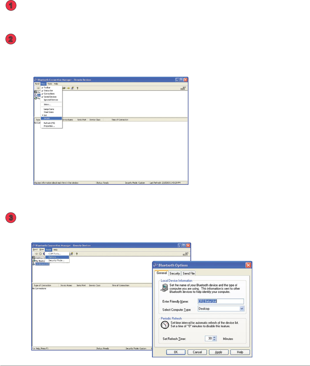
Quickstart Guide for Connecting the CR2 Bluetooth® Radio
to the 3Com® Wireless Bluetooth USB Device # 3CREB96
Follow the instructions that came with the 3Com device and install on the host
computer you wish to utilize.
Once you have properly installed the device, open the Bluetooth Connection
Manager. In the View menu select to view the Toolbar, Status Bar, Connections,
Saved Devices, Ignored Devices and Details.
Under the Tools menu select Options. Under the General tab, make sure to select
your appropriate computer type. When Done click OK.
1
2
3
CR2 User’s Manual Draft_022803_AS - 82
CR2 User’s Manual Draft_022803_AS - 83
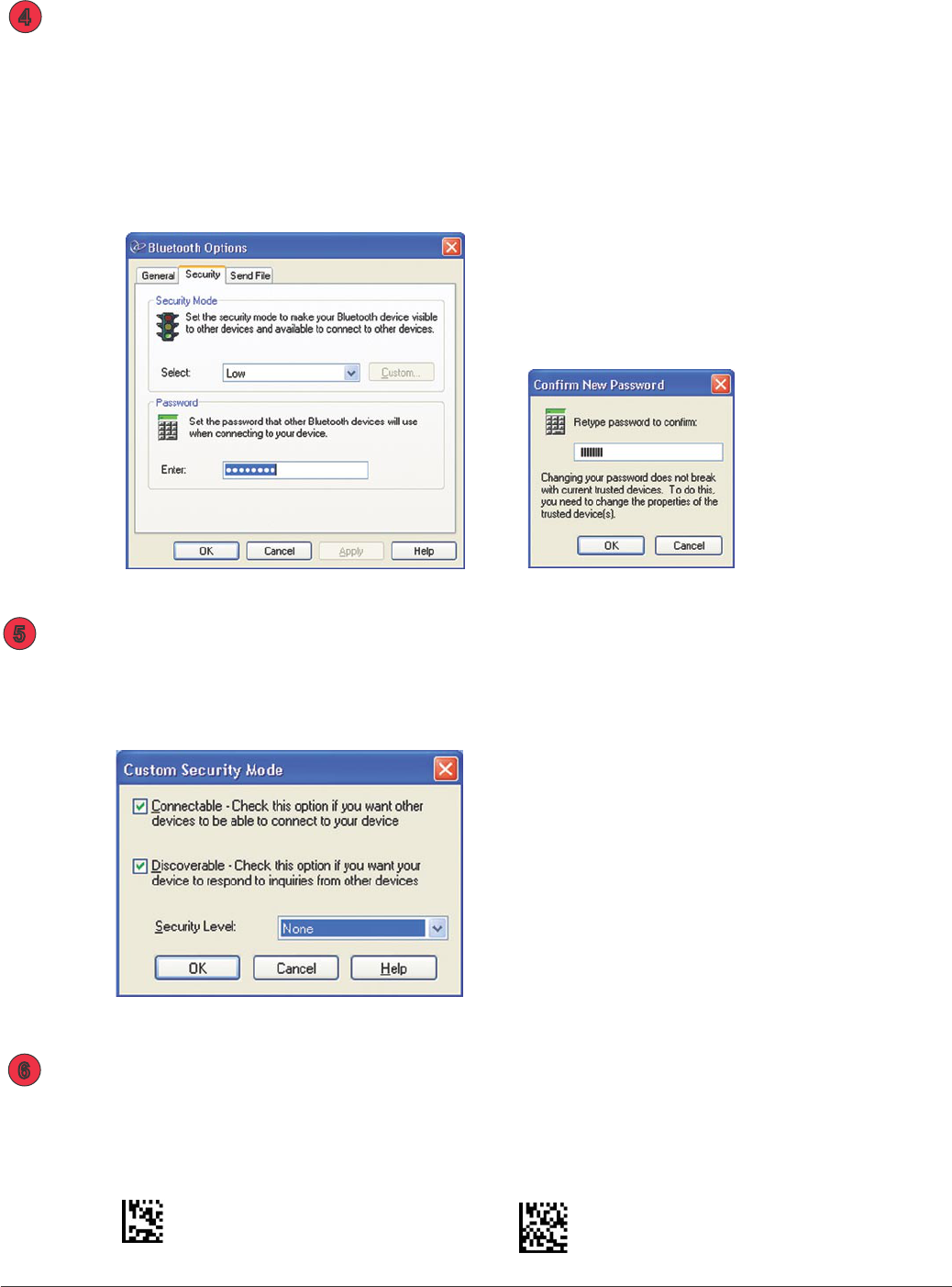
Under the Tools menu select Options. Under the Security tab, make sure
to select the Low security option under Security Mode. At this point you
will have to enter your Bluetooth PIN #. Your PIN # is the same as the serial
number of your reader. The serial number is located on a sticker behind the
battery. You may also access the PIN # by scanning a code on page 53 in
the CR2 Users Manual. Once you have the Radio PIN # enter it in the
password box. When done click OK.
To enable the CR2 unit for RF communication, scan the Reset code then scan
the Enable RF codes below:
Reset to Factory Defaults Enable RF Communication Mode
4
6
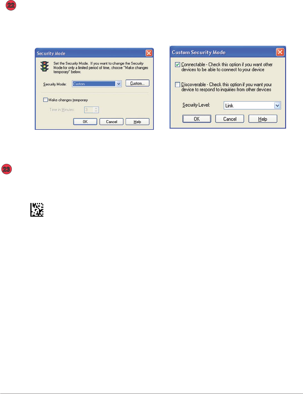
Under the Tools Menu, select Secuity Mode. Set to Security Mode to Custom and
click on Custom button. Under Custom Security Mode screen make device Connect-
able and Discoverable. Set the Security Level to none. When done click on OK.
5
Note: For beta units the
temporary password is:
12345678
CR2 User’s Manual Draft_022803_AS - 82
CR2 User’s Manual Draft_022803_AS - 83
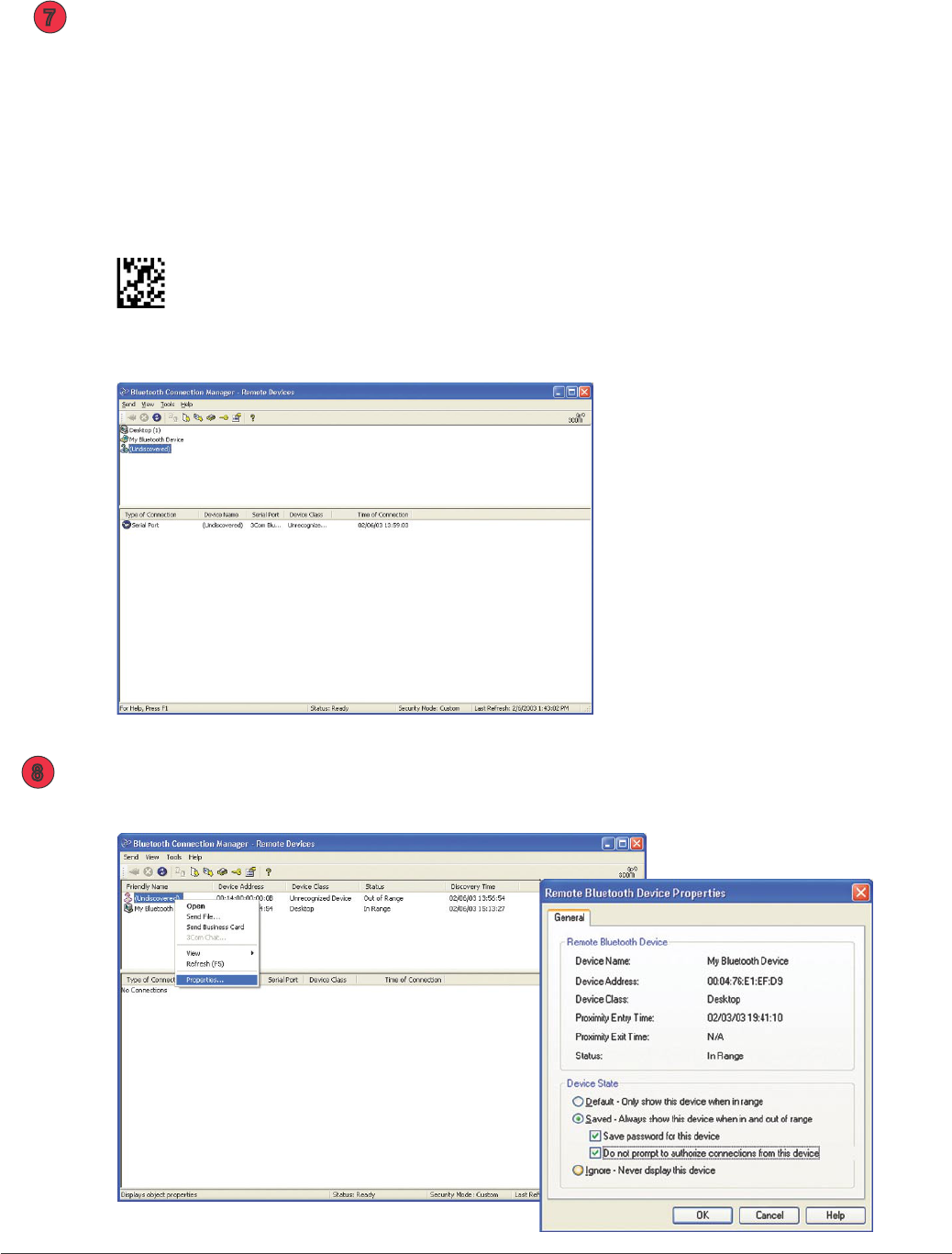
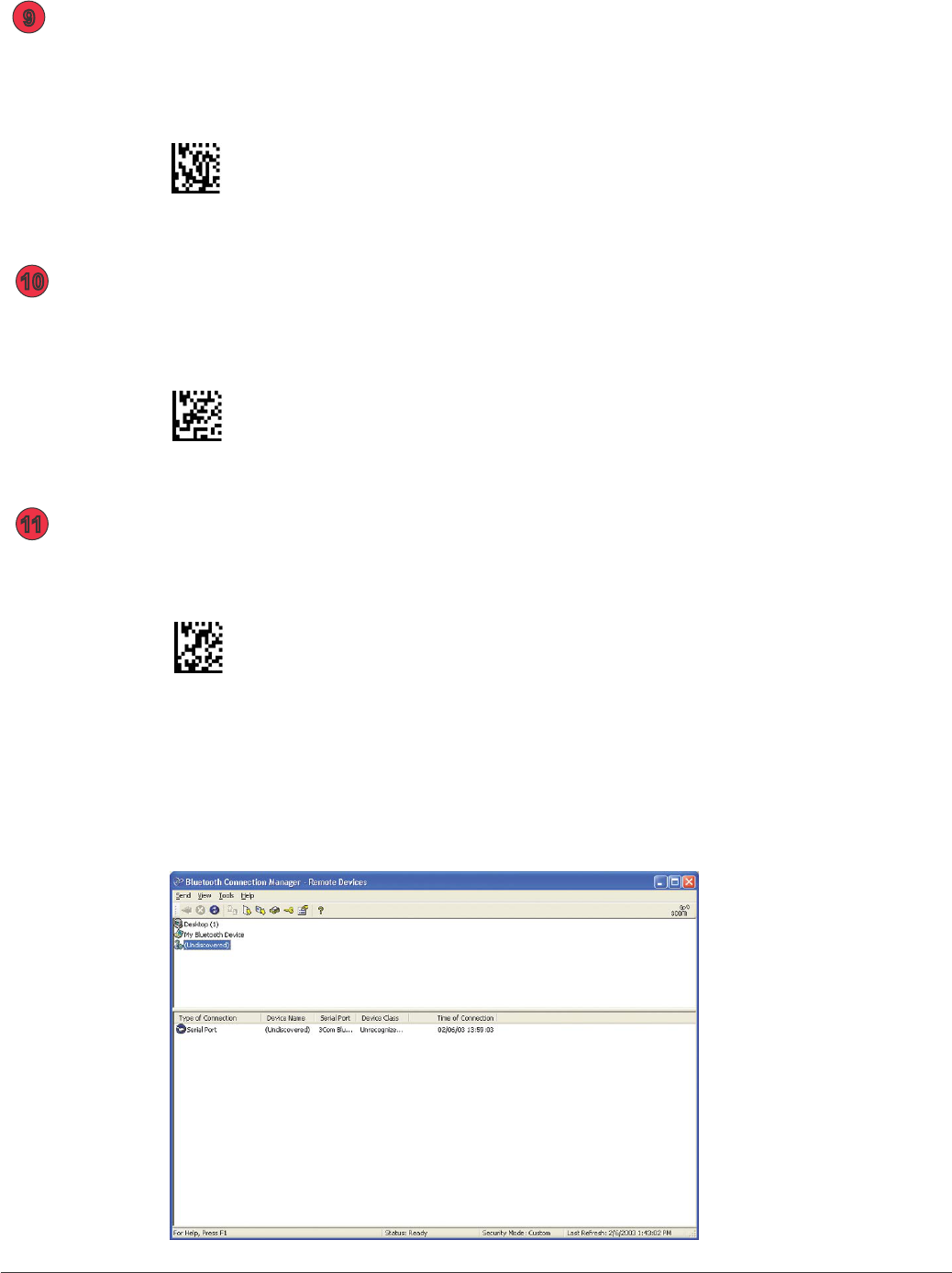
Scan the code below to inquire and connect to the desired device. It may take
20 - 30 seconds for the devices to connect. Observe the connection status
check-mark on the device ICON in the Bluetooth Connection Manager upper
screen and in the serial port connection at the bottom of the screen.
Note: For Beta units your device name will come up as undiscovered
Inquire and Connect
7
When the ICON appears in upper screen, right click on it and select
Properties. Save Password and do not prompt to authorize connections.
8
CR2 User’s Manual Draft_022803_AS - 84
CR2 User’s Manual Draft_022803_AS - 85
Disconnect from the CR2 unit by scanning the code below.
Wait 20-30 seconds for the devices to disconnect.
Disconnect
9
Scan the following code below to enable device pairing:
Enable Pairing Mode
10
Scan to inquire and connect to the desired device.
Inquire and Connect
Note: It may take 20 - 30 seconds for the devices to connect. Observe
the connection status check-mark on the device ICON in the Bluetooth
Connection Manager upper screen and in the serial port connection
at the bottom of the screen.
11
CR2 User’s Manual Draft_022803_AS - 84
CR2 User’s Manual Draft_022803_AS - 85
Disconnect from the CR2 unit by scanning the code below.
Wait 20-30 seconds for the devices to disconnect.
Disconnect
Scan the following code below to enable device pairing:
Enable Pairing Mode
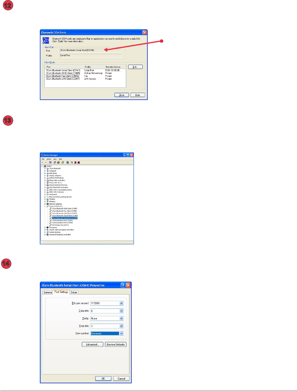
Under the Tools menu select COM ports. The application will connect
to the serial host COM port shown in the menu below. Click Close.
12
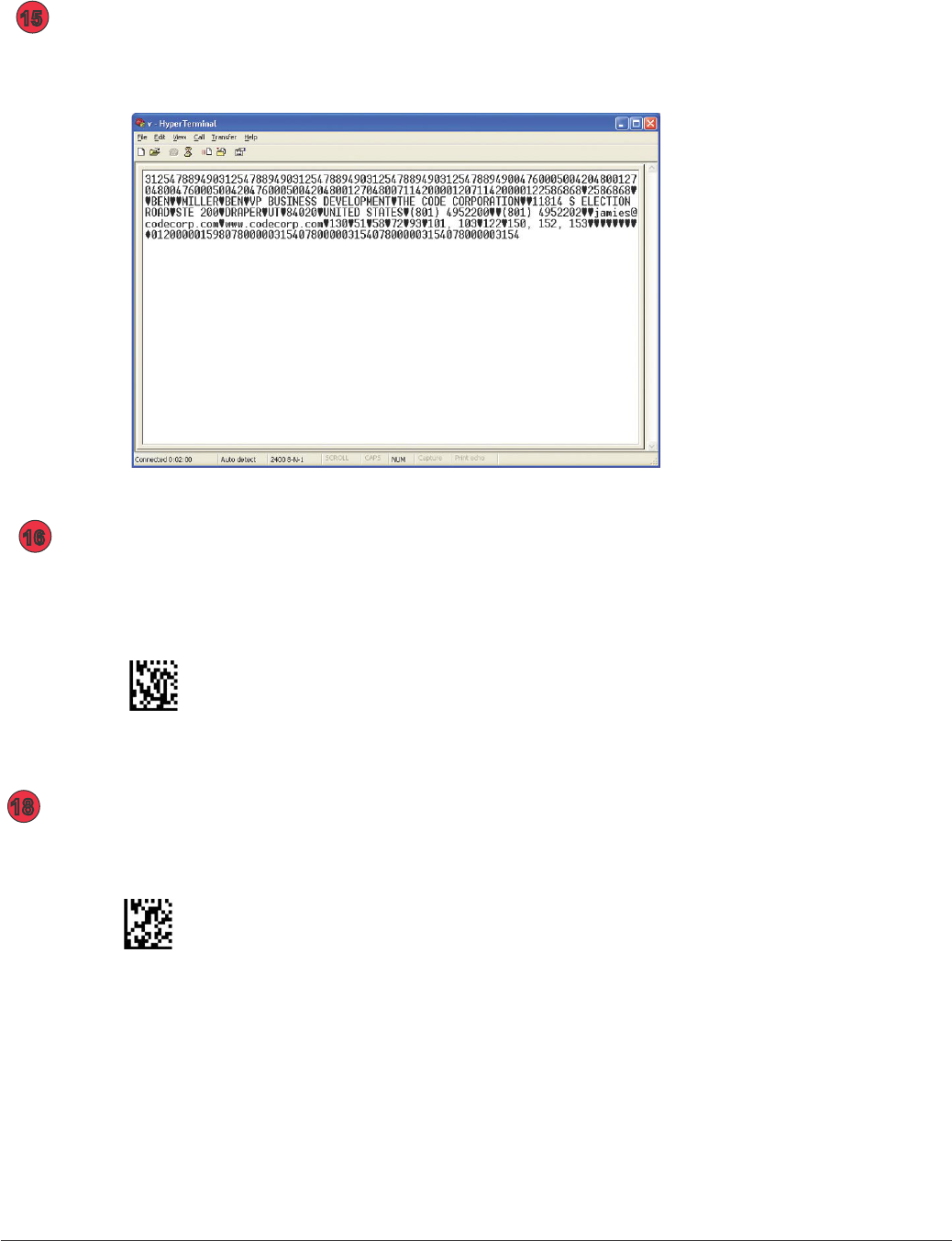
On your host, right click the My Computer icon on your desktop.
Open Properties. Under the Hardware tab select Device Manager
button. Double click on the 3Com Serial Bluetooth Host.
13
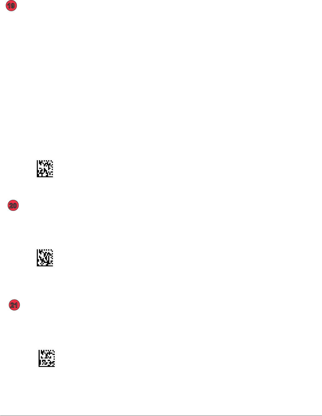
Make sure to match the settings of the port to the below settings:
14
CR2 User’s Manual Draft_022803_AS - 86
CR2 User’s Manual Draft_022803_AS - 87
Disconnect from the CR2 unit by scanning the code below. Wait
20-30 seconds for the devices to disconnect.
Disconnect
Open an application and begin scanning codes to verify data output
(make sure the application is set to the host COM port observed in the
previous steps).
15
16
Scan the code to inquire and connect to the desired device.
Inquire and Connect
Note: It may take 20 - 30 seconds for the devices to connect. Observe
the connection status check-mark on the device ICON in the Bluetooth
Connection Manager upper screen and in the serial port connection
at the bottom of the screen.
18
CR2 User’s Manual Draft_022803_AS - 86
CR2 User’s Manual Draft_022803_AS - 87
Open the sheet of labels that came with your CR2 unit. The CR2 can save
up to 256 bonded hosts. You can instantly connect to a host by associating it
with a label on the sheet. Follow the steps below to associate a host with a label:
1. Scan the Save 001 code from the label sheet.
2. Peel the Connect 001 label off and stick it on the host.
When a user now scans the Connect 001 code the CR2 will instantly
link to that device. If you wish to associate more than 25 devices
please contact a Code representative.
If you would like to test the functionality, scan the following code:
Save 001
19
Disconnect from the CR2 unit by scanning the code below.
Wait 20-30 seconds for the devices to disconnect.
Disconnect
20
Reconnect to the host by scanning the Connect 001 code below.
Wait 20-30 seconds for the devices to connect.
Connect 001
21
CR2 User’s Manual Draft_022803_AS - 88
CR2 User’s Manual Draft_022803_AS - 89
Under the Tools Menu, select Secuity Mode. Set to Custom and click on
Custom button.Under Custom Security Mode screen make sure Connectable
box is checked but deselect the Discoverable box. Set the Security Level to Link.
When Done click on OK.
22
Scan the code below to save the settings on your Reader.
Save Settings on Reader
23

CR2 User’s Manual Draft_022803_AS - 88
CR2 User’s Manual Draft_022803_AS - 89
Appendix B - Setting up a Network
of Bluetooth Enabled Devices

CR2 User’s Manual Draft_022803_AS - 90
CR2 User’s Manual Draft_022803_AS - 91

CR2 User’s Manual Draft_022803_AS - 90
CR2 User’s Manual Draft_022803_AS - 91
Appendix C - Upgrading CR2 Firmware
CR2 User’s Manual Draft_022803_AS - 92
CR2 User’s Manual Draft_022803_AS - 93
Insert the CR2 Firmware CD in a host computer and copy the CR2 Firmware folder on the CD
to your Desktop. If you were emailed a version, please save the les included in the email to
the Desktop in a folder called CR2 Firmware.
In the CR2 Firmware folder on the Desktop, open the CR2 Firmware Dowloader software by
double-clicking on the red arrows Icon.
Attach your CR2 unit to the host with the USB interface.
Scan the code below to set the CR2 unit to USB Native Communication mode:
USB Native
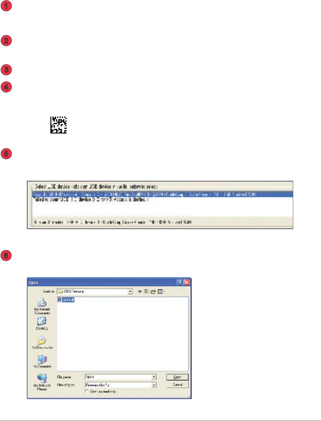
Verify that your CR2 unit is detected by the CR2 Firmware Dowloader software by checking
if the devices name appeards in the USB Device window (gure 1).
With the browse button select the rmware le to download. The correct le is located in the
CR2 Firmware folder on the Desktop. Highlight the le and click Open.
1
2
3
4
6
5
gure 1
Instructions for Downloading CR2 Firmware
gure 2
CR2 User’s Manual Draft_022803_AS - 92
CR2 User’s Manual Draft_022803_AS - 93
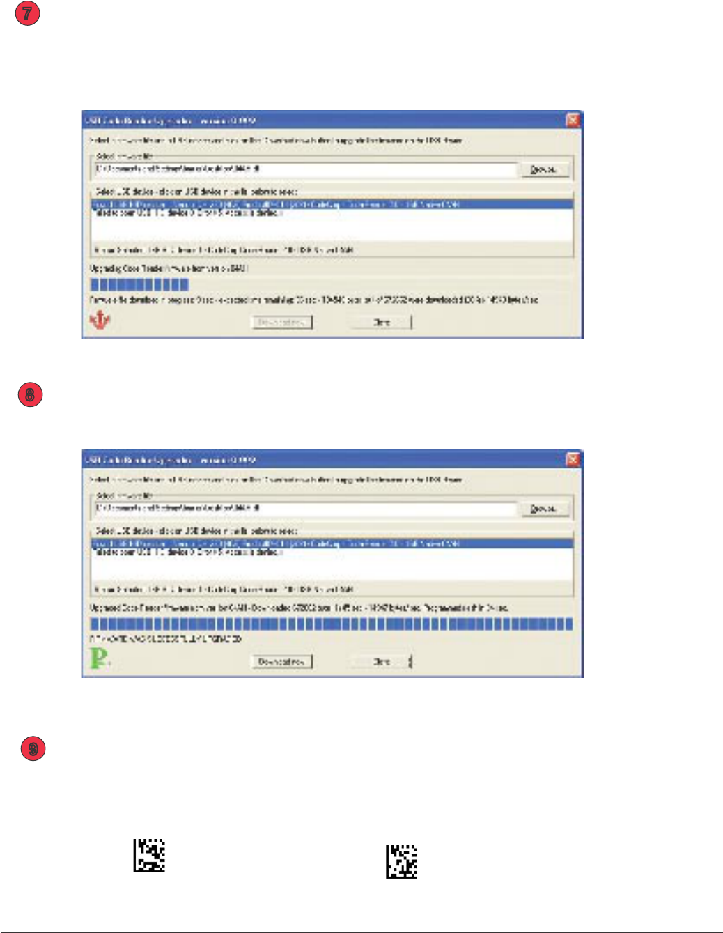
Click on the Download Now button. Firmware will automatically be uploaded to
your CR2 unit (gure 4).
Note: DO NOT unplug the unit while upgrading rmware!
When done uploading, you will see a Pass Icon in the lower left corner and a note
saying FIRMWARE HAS BEEN SUCCESSFULLY UPGRADED (gure 4).
Power off your reader. Power the unit back up then scan the Reset to Factory Defaults
code then Save Settings code:
Reset to Factory Defaults Save Settings
7
8
9
gure 3
gure 4