Coen Consultant VDUL5NA Modular transmitter User Manual VDU user s guide v2 20
Coencorp Consultant Corporation Modular transmitter VDU user s guide v2 20
UserManual.wiki
>
Coen Consultant
>
VDUL5NA User Manual
>
VDU Manual
Contents
1.
Installation Guide
2.
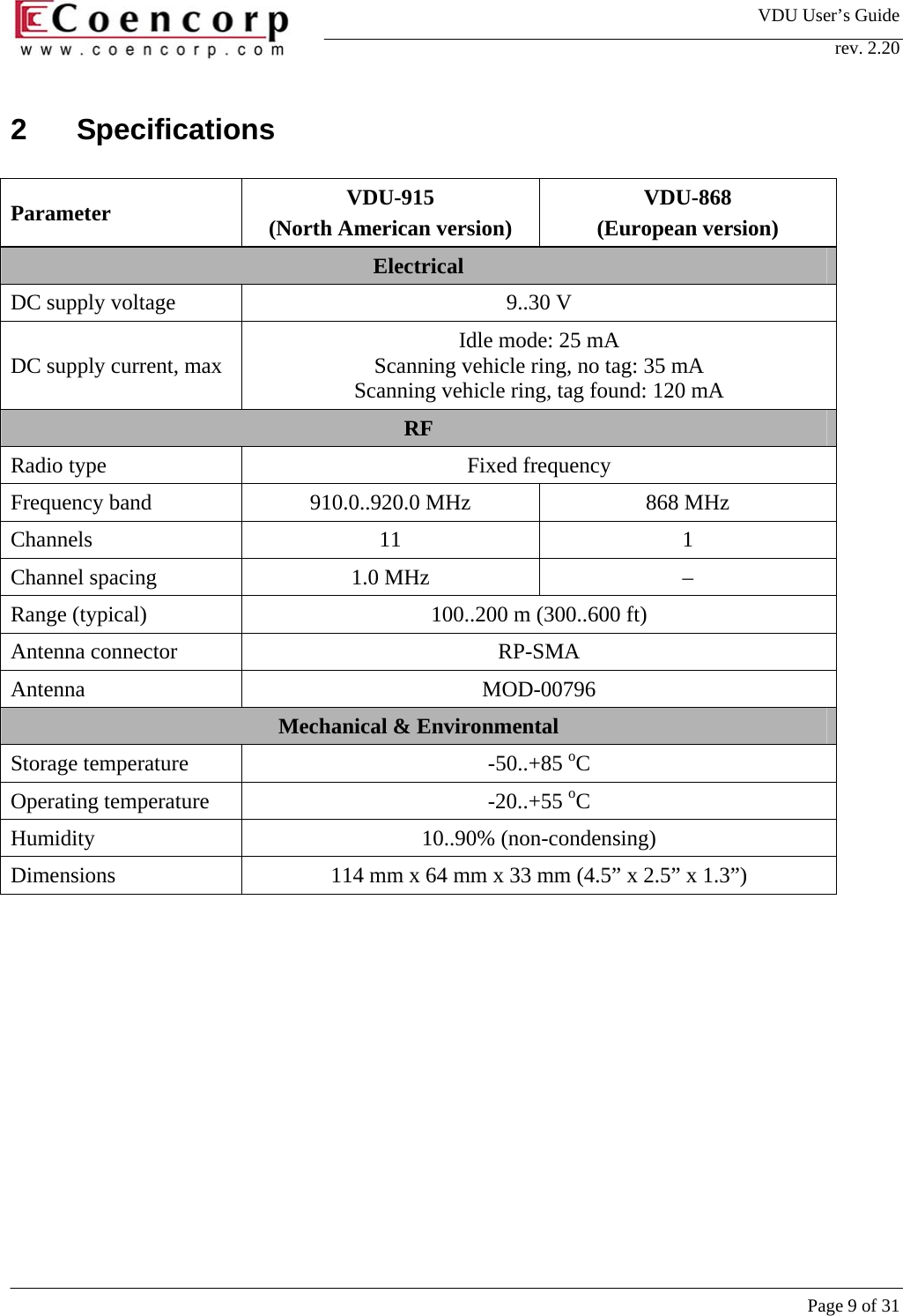
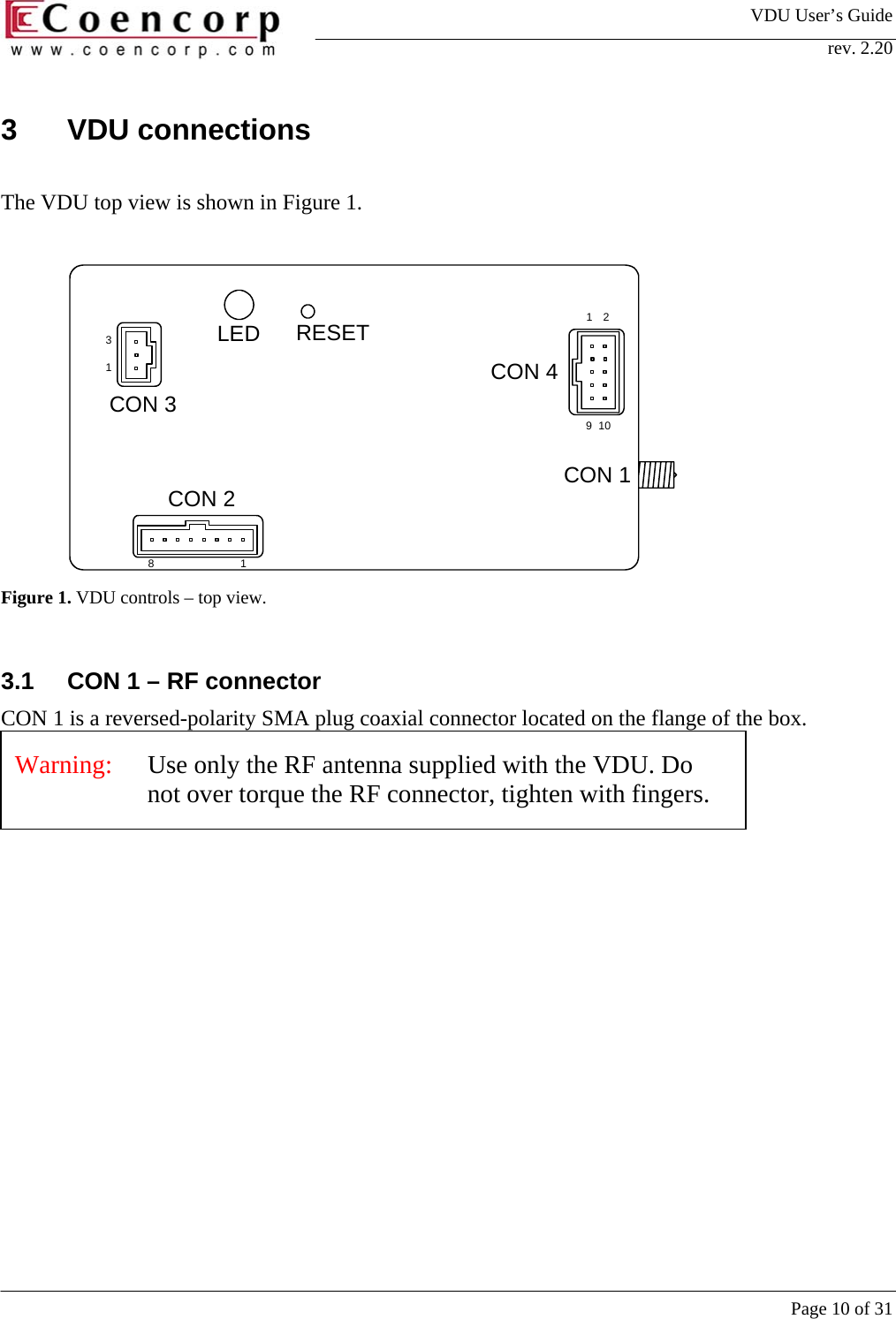
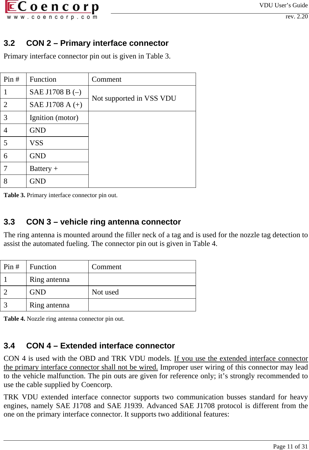
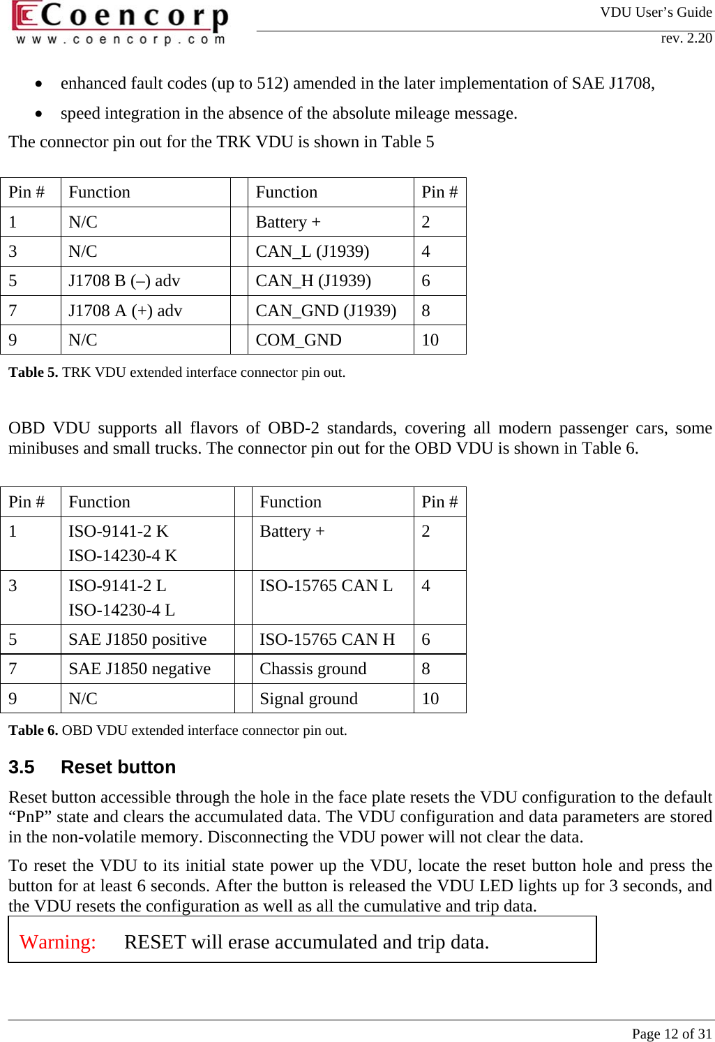
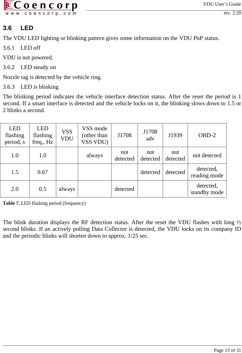
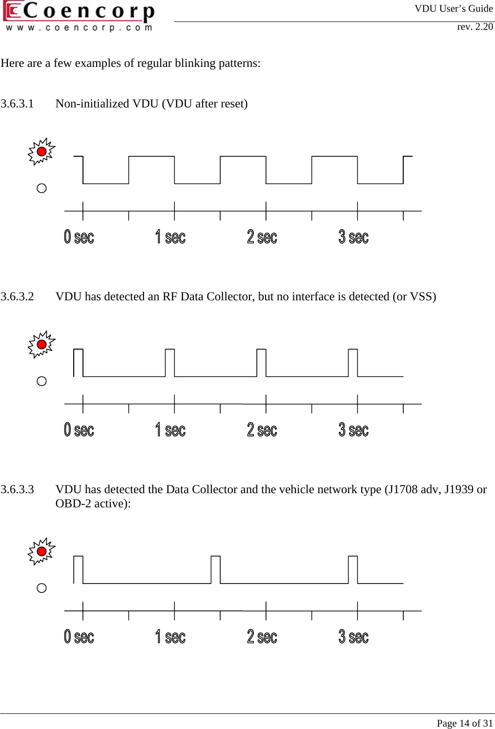
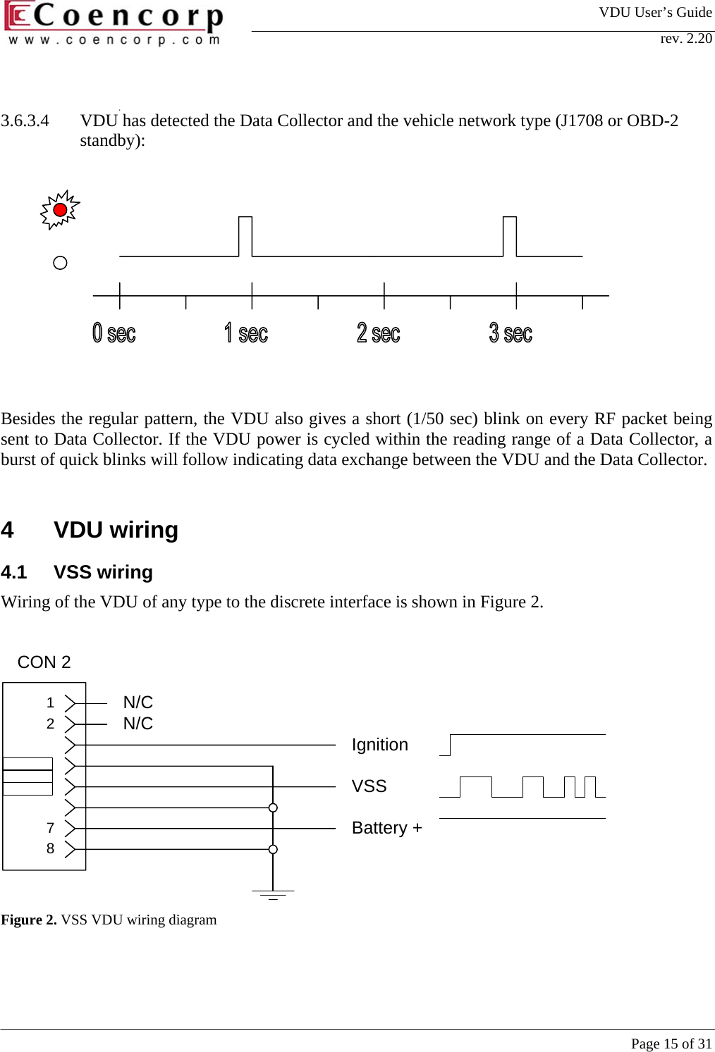
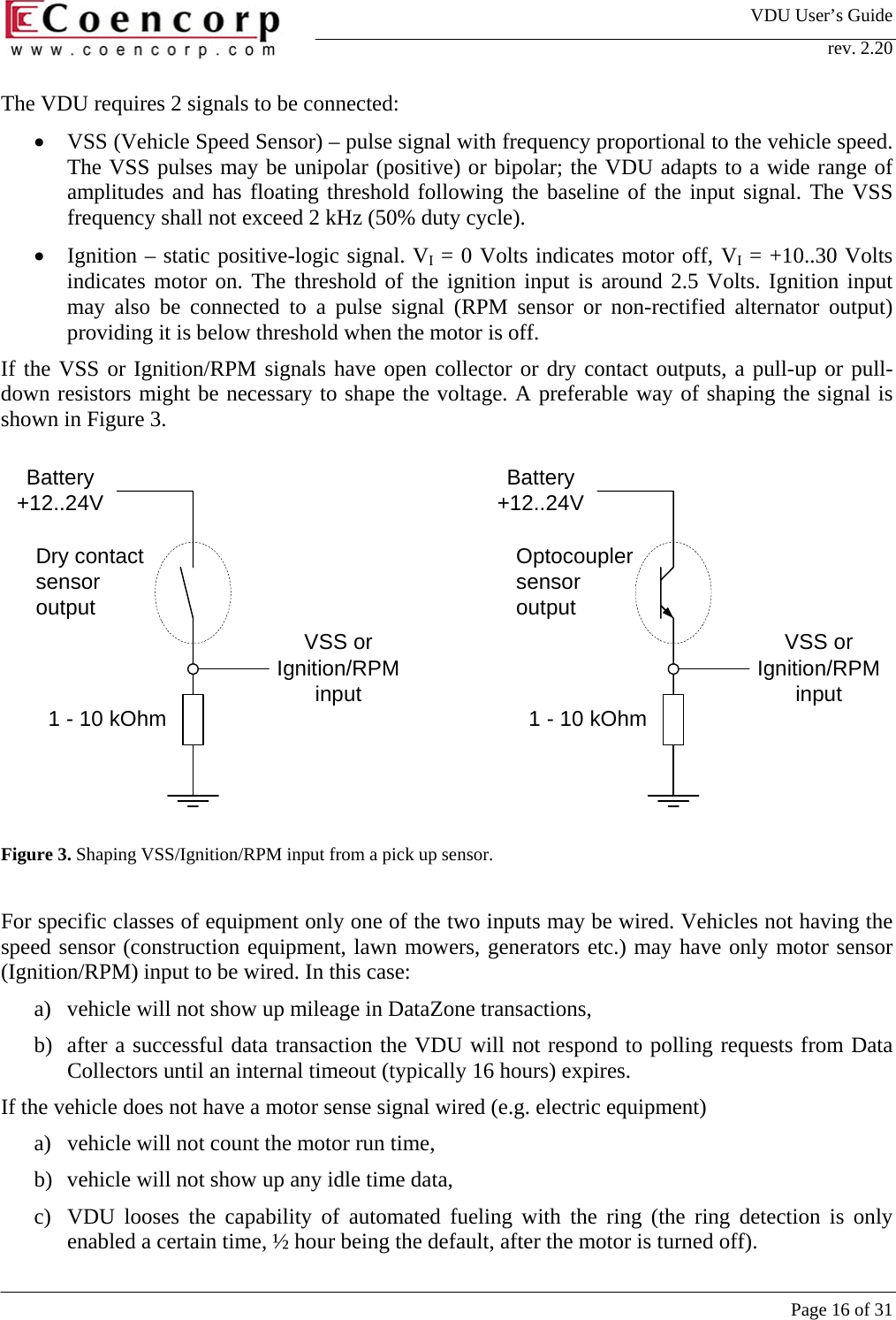
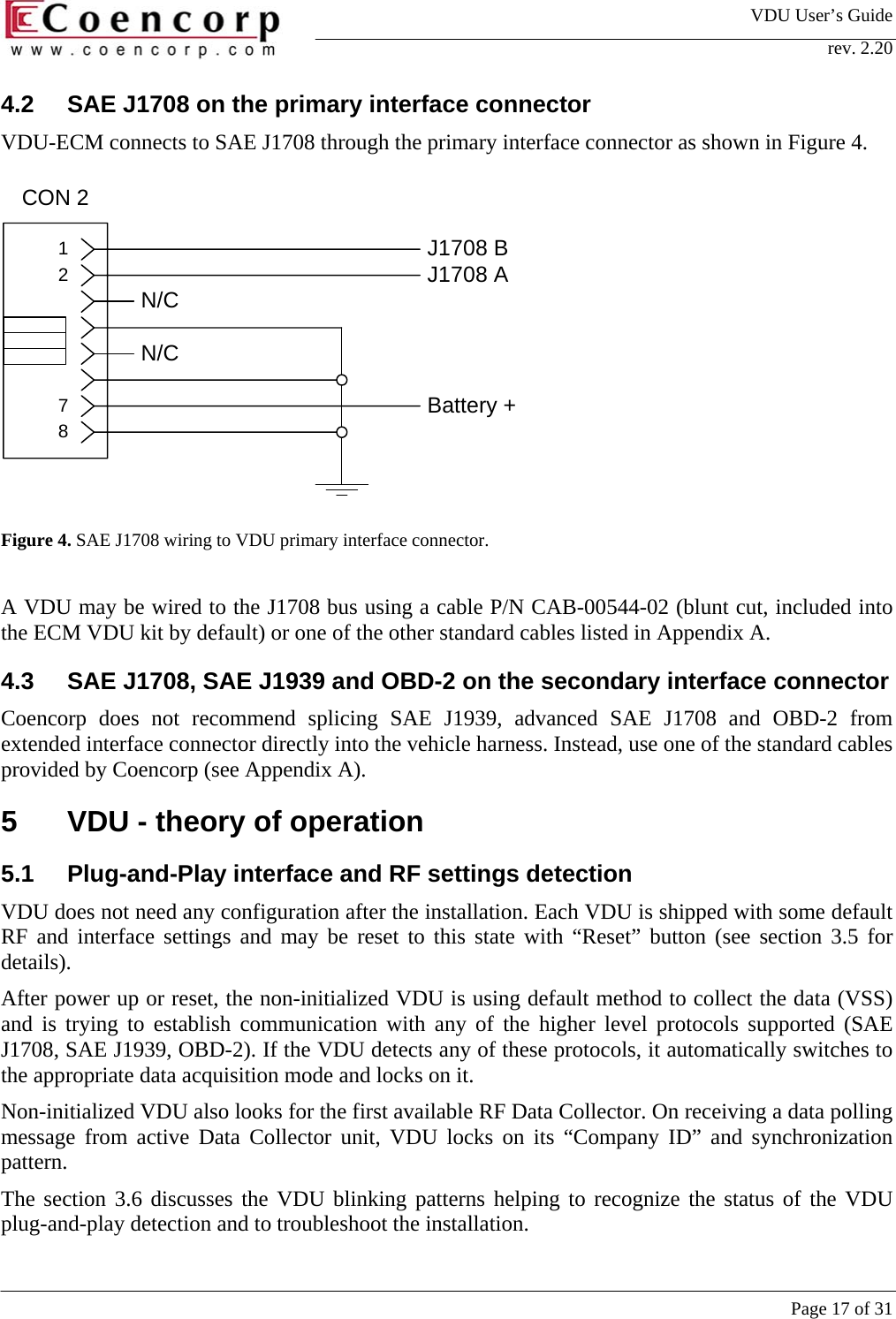
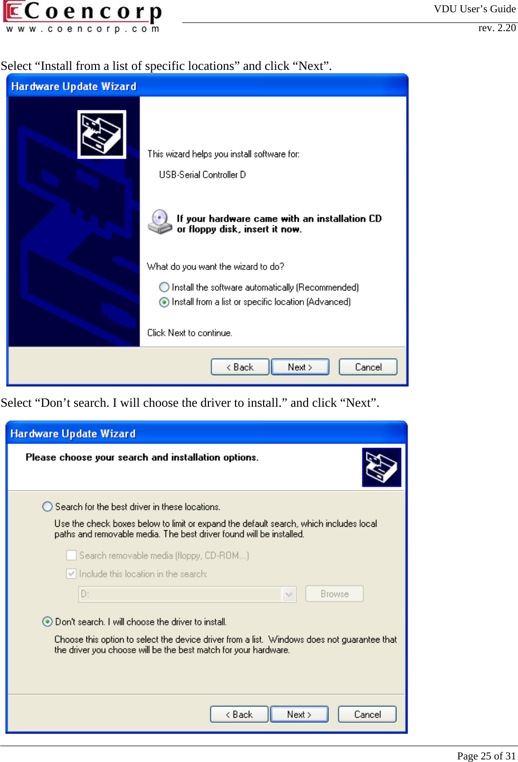
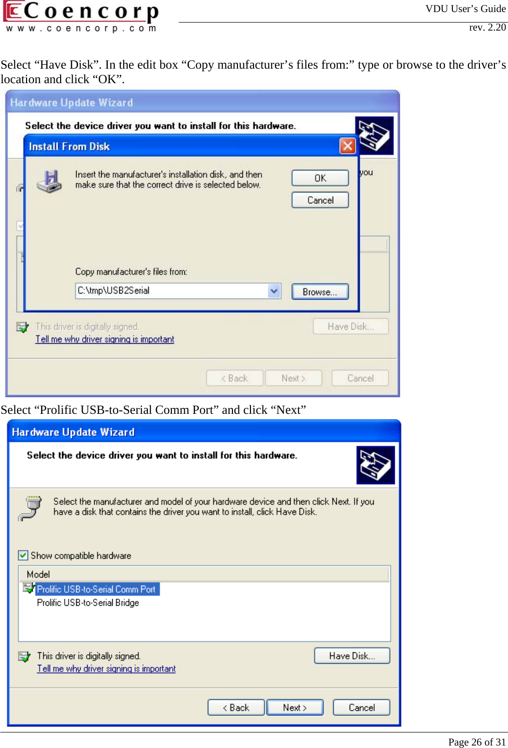
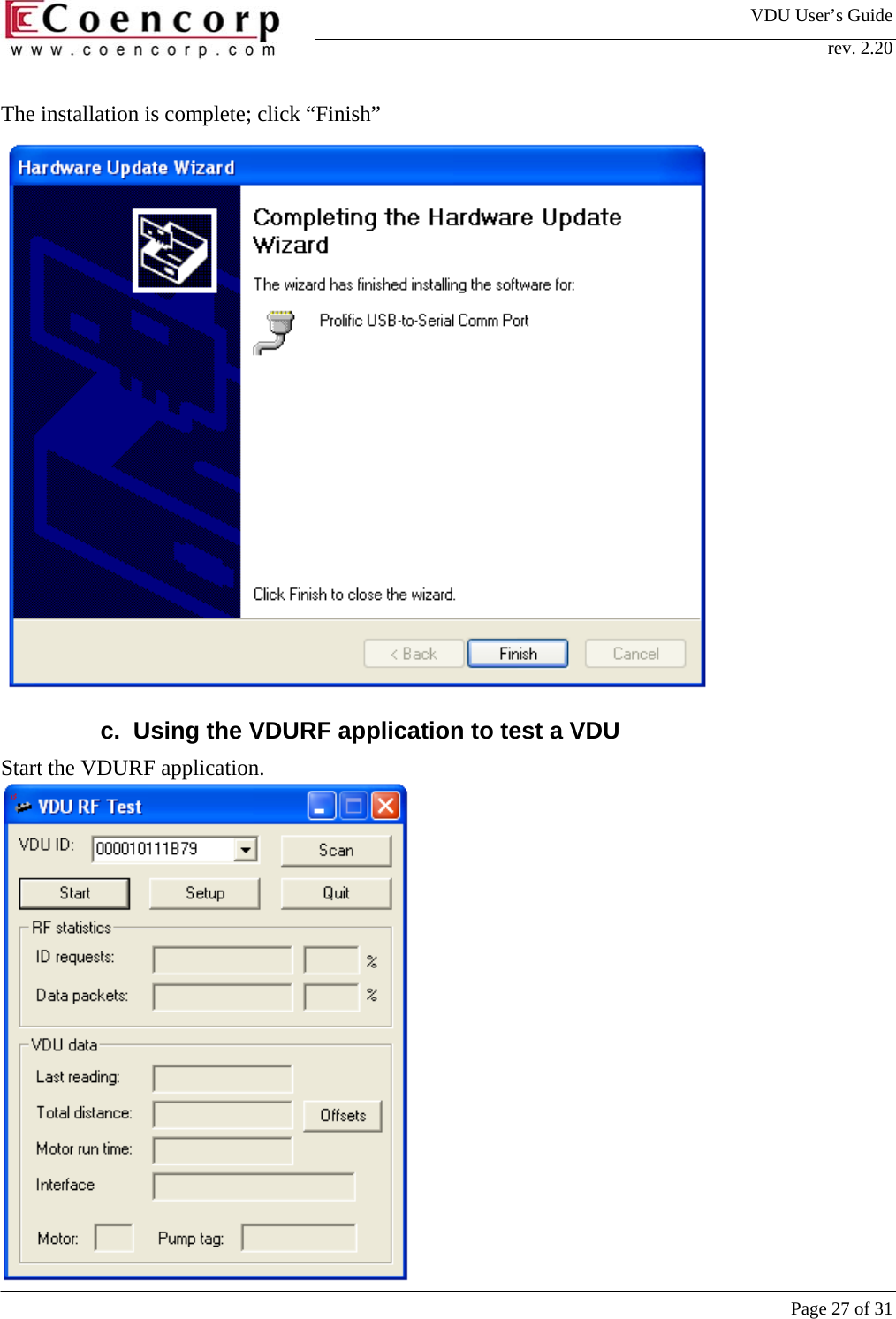
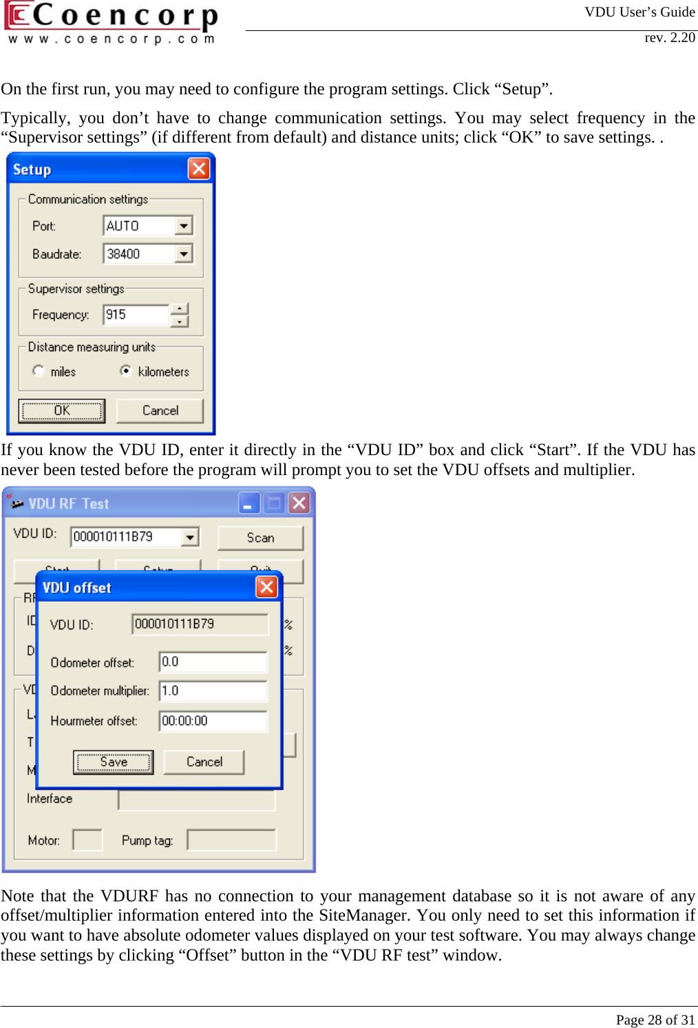
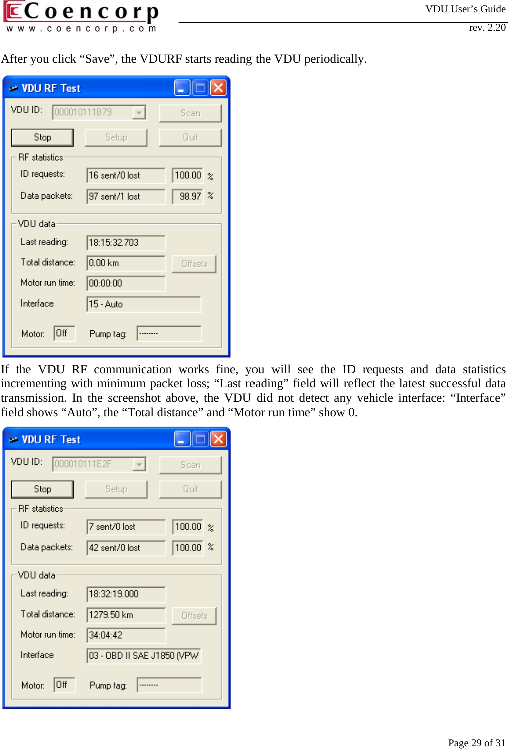
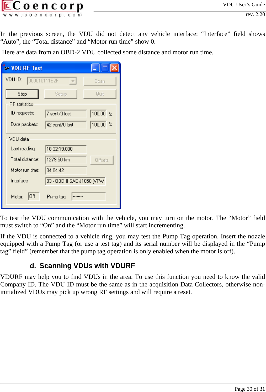
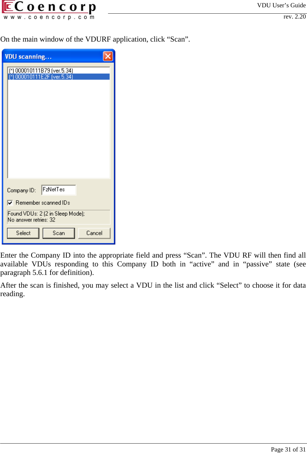
VDU Manual
VDU Manual
Navigation menu
Upload a User Manual
Namespaces
Wiki Guide
HTML
PDF
Info
Views
User Manual
Discussion / Help
Navigation