Coen Consultant VDUL5NA Modular transmitter User Manual DC install guide v1 12
Coencorp Consultant Corporation Modular transmitter DC install guide v1 12
Contents
- 1. Installation Guide
- 2. VDU Manual
Installation Guide

8 Place du Commerce, suite 100,
Brossard QC Canada J4W 3H2
http://www.coencorp.com
mailto:info@coencorp.com
Tel: 1-450-672-4222
Toll free (US & Canada):
1-866-COENCORP
Fax: 1-450-672-6038
Created on: 5/29/2009 9:59 AM
Created by: Serge Kopikov
Document revision: 1.12
FleetZone
Data Collector
Installation Guide

Data Collector Installation Guide
revision 1.12
Page 2 of 11
Copyright
This document cannot be redistributed to third party, reproduced or modified
without written permission from Coencorp.
Disclaimer
The information in this document is subject to change without notice. While
the information contained herein is assumed to be accurate, Coencorp
assumes no responsibility for any errors or omissions.

Data Collector Installation Guide
revision 1.12
Page 3 of 11
Table of contents
1 Introduction ................................................................................................................................................................. 5
2 Specifications .............................................................................................................................................................. 6
3 Installing Data Collector.............................................................................................................................................. 7
4 Connecting Data Collector to a SiteController.......................................................................................................... 10
Data Collector Installation Guide
revision 1.12
Page 4 of 11
The North American versions of RF devices included in this manual contain the board having the
following agency approval numbers:
US/FCC ID VY3-VDUL5NA
CAN/IC ID 7522A-VDUL5NA
The devices included in this manual were tested with the following antennae:
Device Antenna P/N (Coencorp)
FGD-00582-02 (North American ver.)
FGD-00582-03 (European ver.)
MOD-00797 with RPSMA
(internally mounted RF antenna)
Warning: Any antenna not explicitly specified in this manual must be tested to
comply with FCC section 15.203 for unique antenna connectors an
d
section 15.249 for emissions.
Warning: Changes or modifications not expressly approved by the party
responsible for compliance could void the user’s authority to operate
the equipment.
Coencorp is not responsible for any radio or TV interference caused
by unauthorized modifications to this equipment.
Warning: This device complies with part 15 of the FCC Rules. Operation is
subject to the following two conditions:
(1) This device may not cause harmful interference and
(2) This device must accept any interference received, including
interference that may cause undesired operation.
Data Collector Installation Guide
revision 1.12
Page 5 of 11
1 Introduction
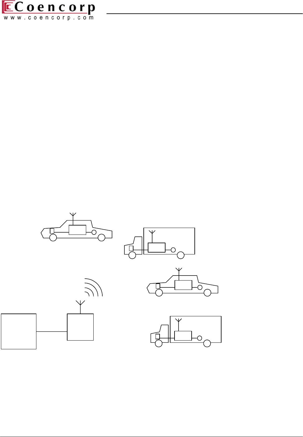
Coencorp RF Data Collector is an RF modem used in Coencorp Fleet and Fuel Management System
to collect data from Vehicle Data Units (VDU) and to assist in the automated fueling sequence.
The RF communication between Data Collector and VDU uses 915 MHz (North American) or 868
MHz (European) frequency bands. The VDU only sends data in response to requests from Data
Collector. The communication has a typical range of 300-600 ft (100-200 m) from the Data
Collector.
The fixed Data Collector is mounted in a standard sealed electrical enclosure suitable for outdoor
use. Besides the standard fixed Data Collector there exists a portable version having the same
hardware and software but packaged in a smaller VDU-like enclosure. The portable version of data
collector may be used for VDU installation tests with a laptop (see the VDU manual for details).
This manual only covers the fixed Data Collector.
The Data Collector communicates with host computer through RS-232 serial port or USB (using
USB-to-Serial adapter).
Site
Controller
RF Data
Collector
VDU
VDU
VDU
VDU
Figure 1. DataZone Site structure
Data Collector Installation Guide
revision 1.12
Page 6 of 11
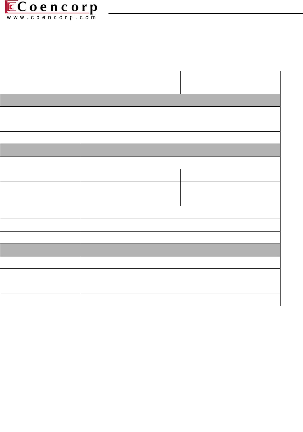
2 Specifications
Parameter FGD-00582-02
(North American version)
FGD-00582-03
(European version)
Electrical
RS-232 baud rate 9600,19200,38400
DC supply voltage 9..25 V
DC supply current, max 30 mA
RF
Radio type Fixed frequency
Frequency band 910.0..920.0 MHz 868 MHz
Channels 11 1
Channel spacing 1.0 MHz –
Range (typical) 100..200 m (300..600 ft)
Antenna connector RP-SMA
Antenna MOD-00797
Mechanical & Environmental
Storage temperature -50..+85 oC
Operating temperature -20..+55 oC
Dimensions 229 mm x 229 mm x 127 mm (9.0” x 9.0” x 5.0”)
Interface connector Screw terminal block
Data Collector Installation Guide
revision 1.12
Page 7 of 11
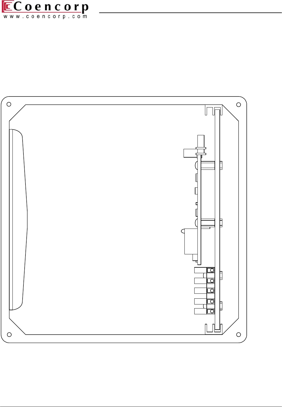
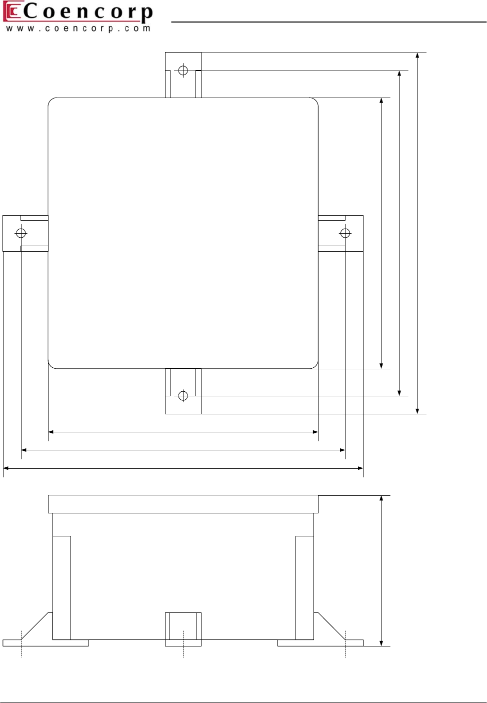
3 Installing Data Collector
A fixed Data Collector connects to a SiteController computer through RS-232 port and does not
require special drivers to be installed on the computer. This section contains mechanical sketches
and electrical wiring diagrams for the installation. The Data Collector is shipped without cables and
connectors: the installer must provide a cable.
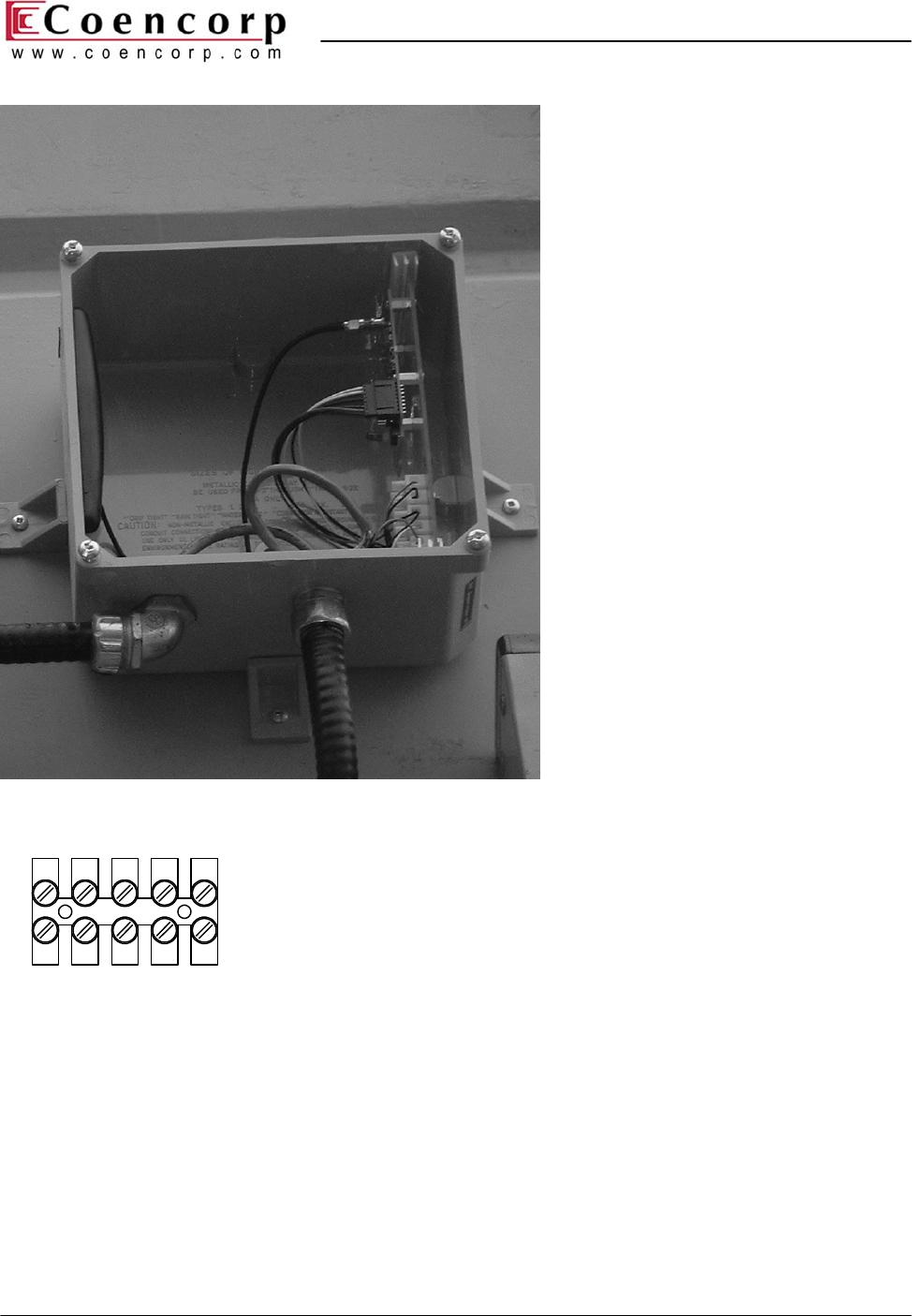
RF board
RF antenna
Terminal block
Mounting plate
Figure 3. Data Collector – internal layout
Data Collector Installation Guide
revision 1.12
Page 8 of 11
9.0" (229 mm)
10.5" (267 mm)
11.5" (292 mm)
9.0" (229 mm)
11.5" (292 mm)
10.5" (267 mm)
5.0" (127 mm)
Figure 2. Data Collector – outside dimensions
Data Collector Installation Guide
revision 1.12
Page 9 of 11
Figure 4. Data Collector mounted on a wall (cover removed)
+12V RET COM TX RX
Figure 5. Data Collector – terminal block
Data Collector Installation Guide
revision 1.12
Page 10 of 11
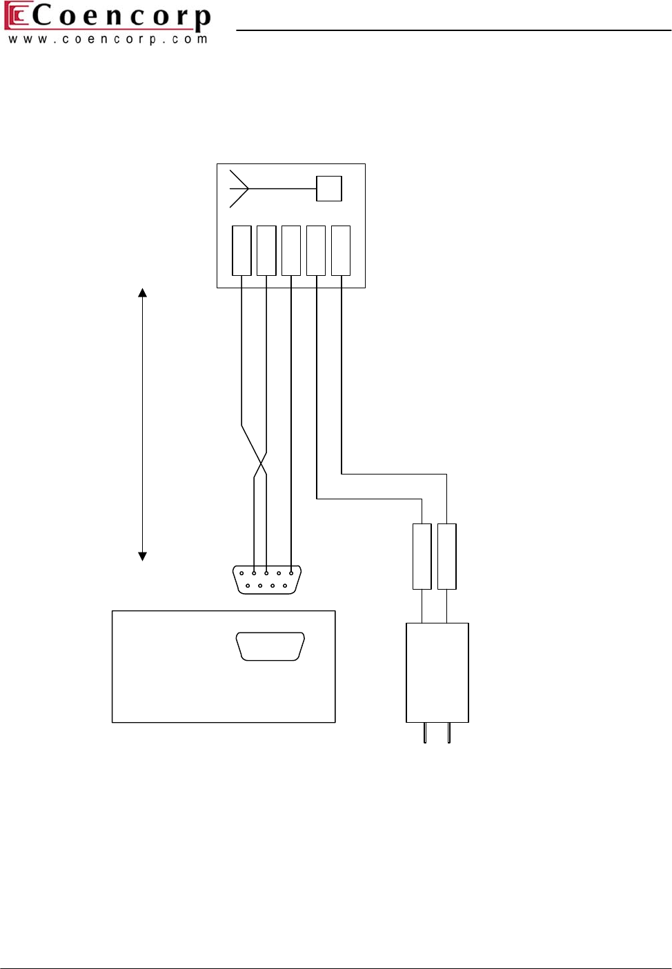
4 Connecting Data Collector to a SiteController
1
DB9-FCOM1
SiteController
RX
TX
COM
RET
12V
-Vout
+Vout
Wall plug power supply
9-12 VDC, 0.5A
RF Data Collector
100' (30 m) max
2345
6789
Figure 6. Data Collector connection to a SiteController through RS-232
Data Collector Installation Guide
revision 1.12
Page 11 of 11
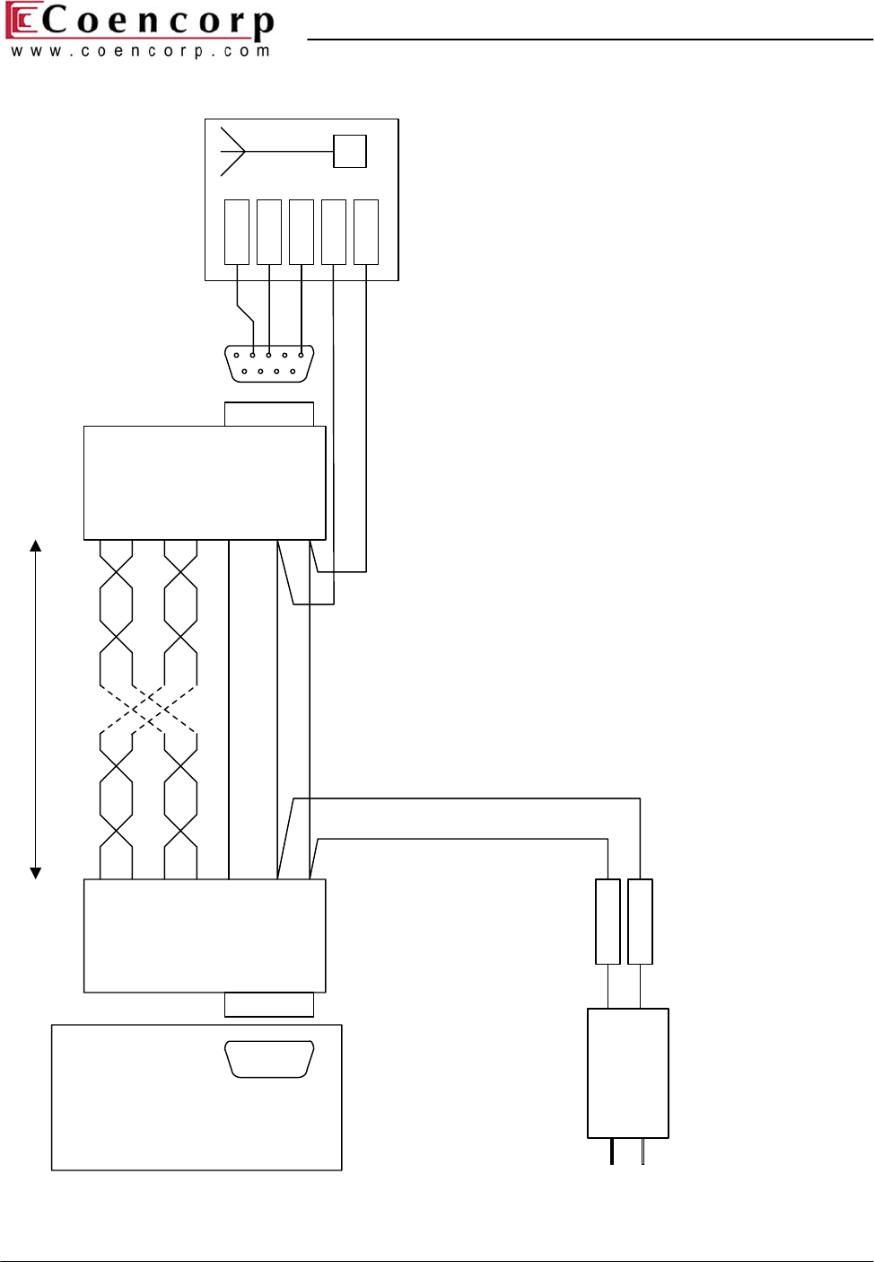
RD(A)
4WSD9OTB
1
DB9-M
COM1
SiteController
RX
TX
COM
RET
12V
-Vout
+Vout
Wall plug power supply
9-12 VDC, 0.5A
RF Data Collector
1000' (300 m) max
2345
6789
TD(B)
RD(B)
COM
COM
+12V
TD(A)
RD(A)
4WSD9OTB
TD(B)
RD(B)
COM
COM
+12V
TD(A)
Figure 7. Data Collector connection to a SiteController through RS-422 (extended cable run).