Cogent Systems SPS-TS FINGERPRINT ACCESS CONTROL READER User Manual Smart Gate Installation English
Cogent Systems Inc FINGERPRINT ACCESS CONTROL READER Smart Gate Installation English
UserManual.wiki
>
Cogent Systems
>
SPS TS User Manual
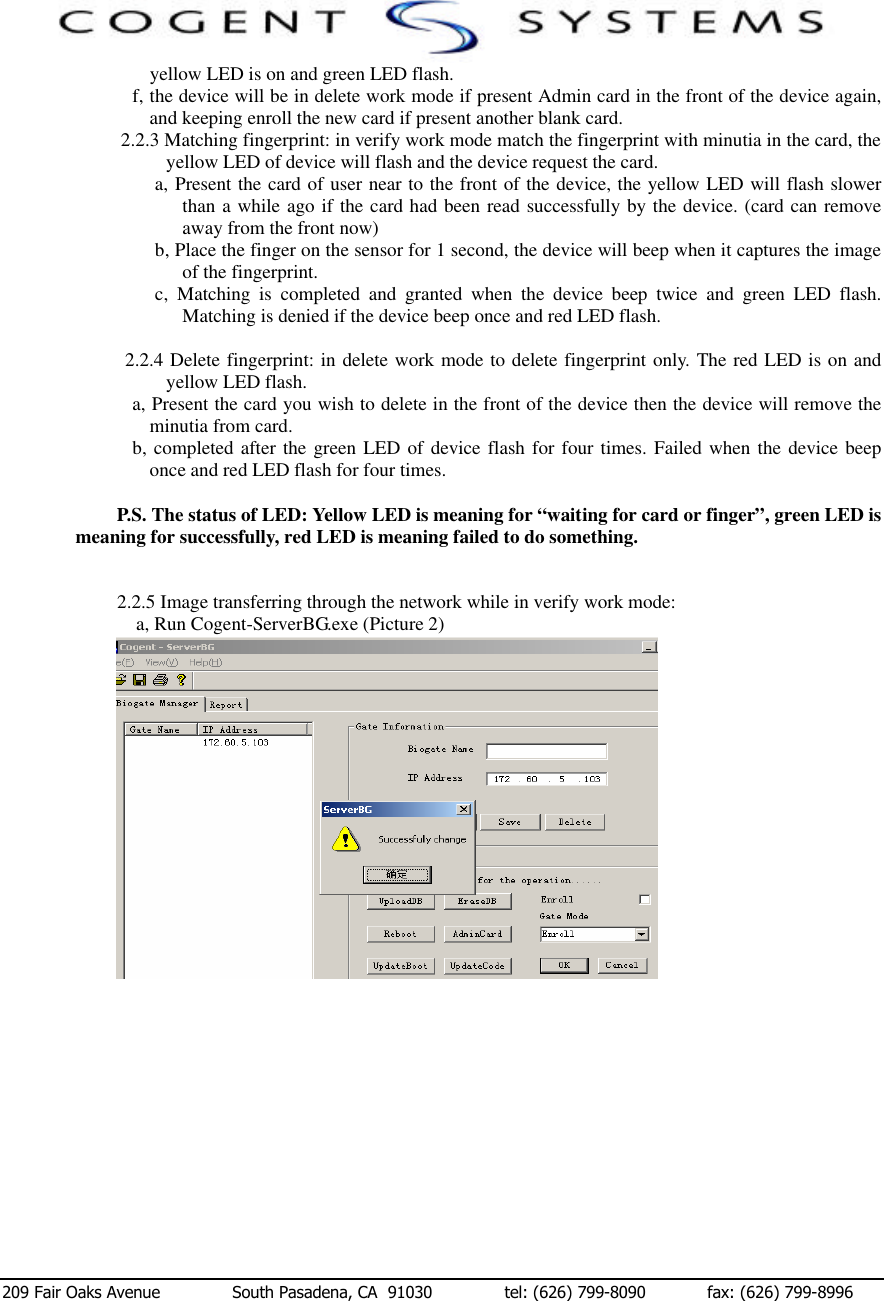
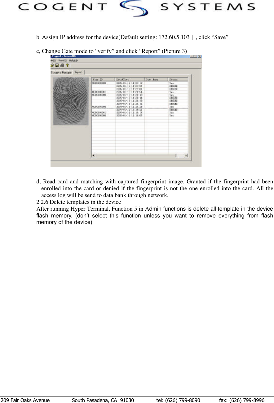
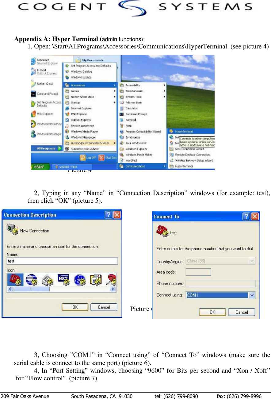
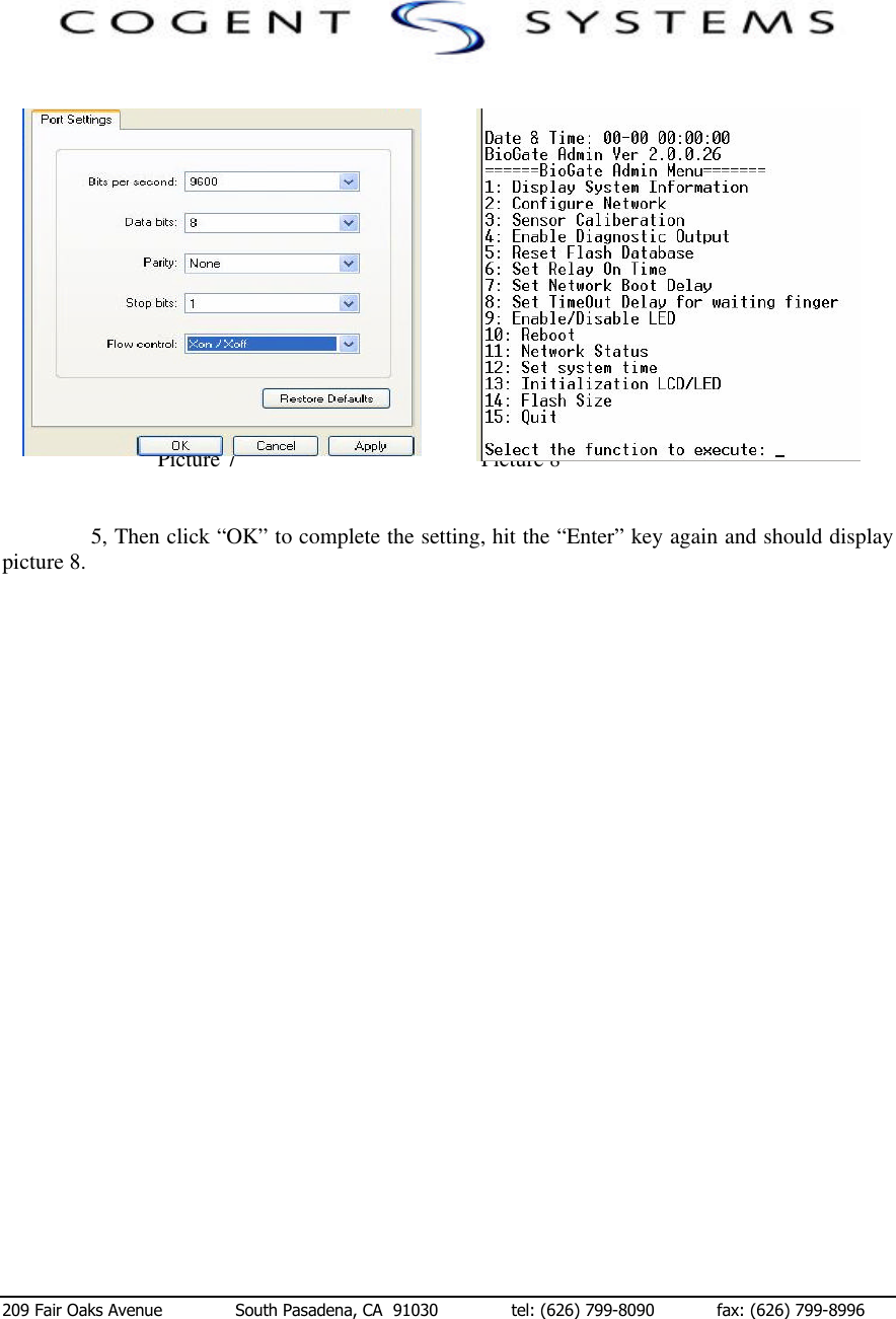
USERS MANUAL
Navigation menu
Upload a User Manual
Namespaces
Wiki Guide
HTML
PDF
Info
Views
User Manual
Discussion / Help
Navigation