Comba Telecom HRU01-6800 ComFlex Series Distributed Antenna System User Manual
Comba Telecom Ltd. ComFlex Series Distributed Antenna System
UserManual.wiki
>
Comba Telecom
>
HRU01 6800 User Manual
User Manual
Navigation menu
Upload a User Manual
Namespaces
Wiki Guide
HTML
PDF
Info
Views
User Manual
Discussion / Help
Navigation

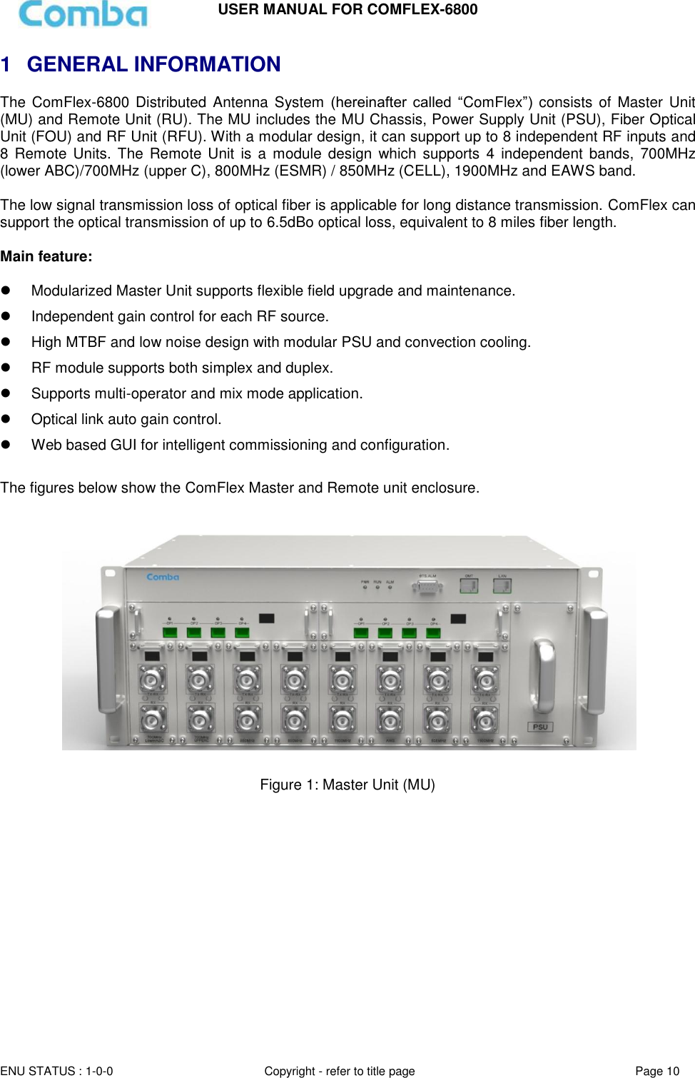
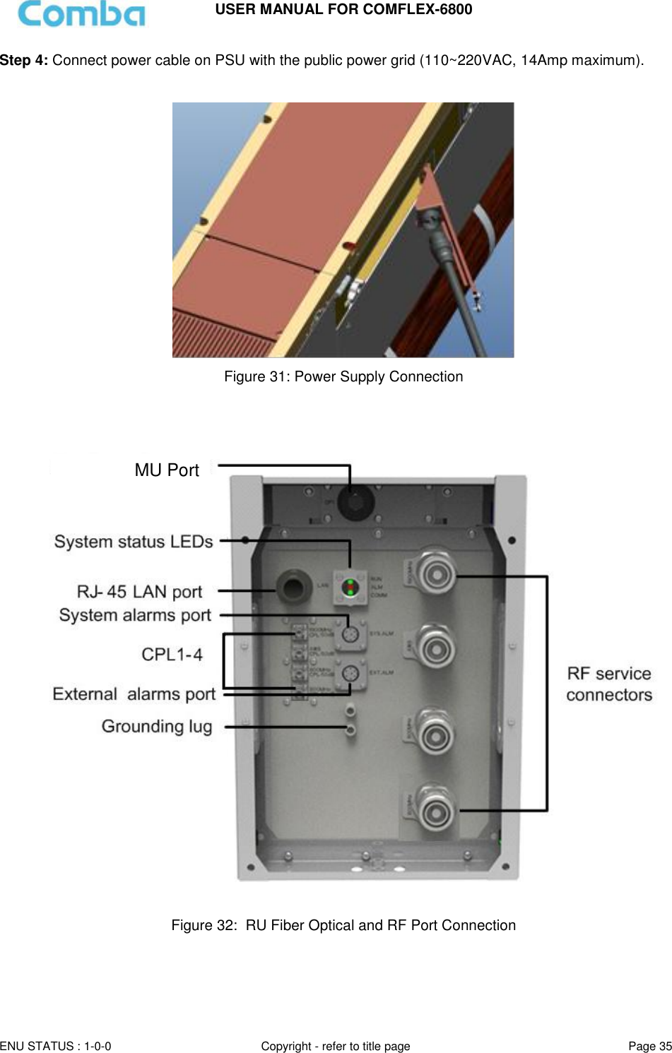
![USER MANUAL FOR COMFLEX-6800 ENU STATUS : 1-0-0 Copyright - refer to title page Page 4 5.2.1 [DEVICES] ............................................................................................................................................... 42 5.2.2 [COMMISSIONING] ................................................................................................................................ 47 5.2.3 [FIRMWARE] .......................................................................................................................................... 47 5.2.4 [MANAGEMENT] .................................................................................................................................... 50 5.3 COMMISSIONING PROCEDURE ................................................................................................................... 60 6 ALARMS AND TROUBLESHOOTING ............................................................................................................. 67 6.1 ALARMS ...................................................................................................................................................... 67 6.2 TROUBLESHOOTING ................................................................................................................................... 68 7 APPENDICES ............................................................................................................................................... 70 7.1 APPENDIX A: TOOLS FOR INSTALLATION AND MAINTENANCE .................................................................... 70 7.2 APPENDIX B: RMA (RETURN MATERIAL AUTHORIZATION) ......................................................................... 71](https://usermanual.wiki/Comba-Telecom/HRU01-6800/User-Guide-3343015-Page-6.png)
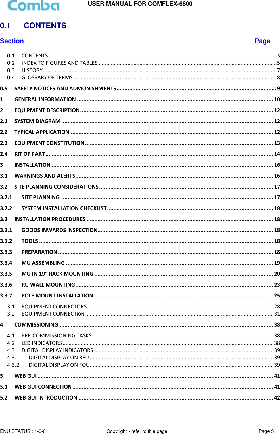
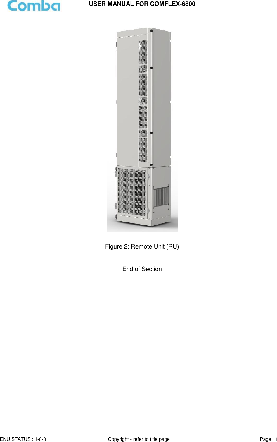
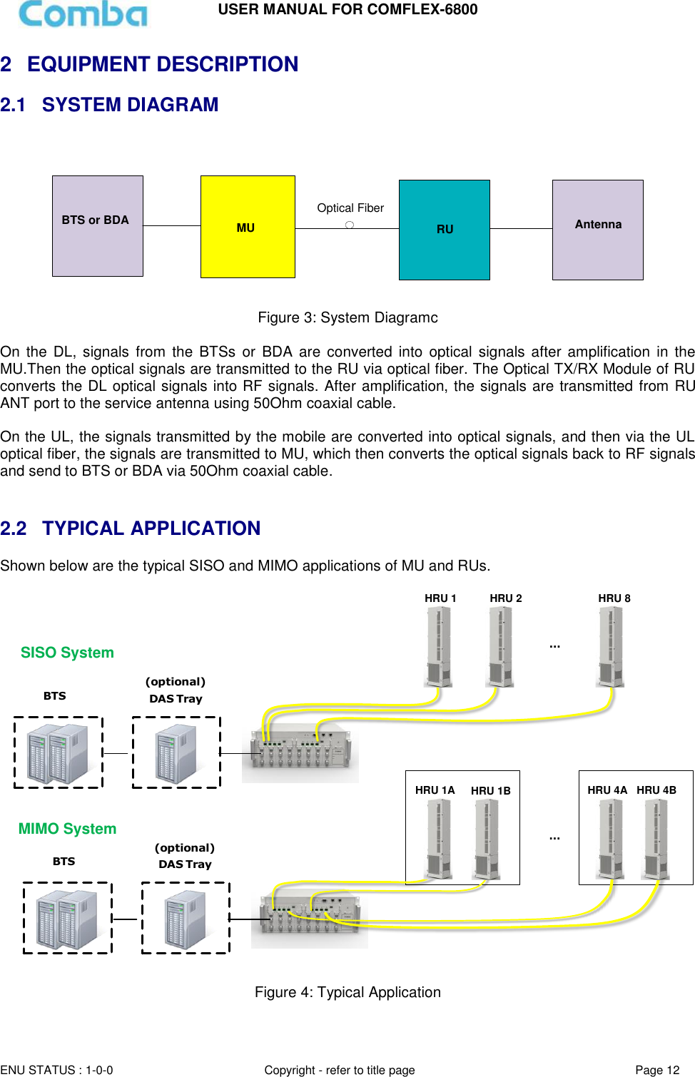
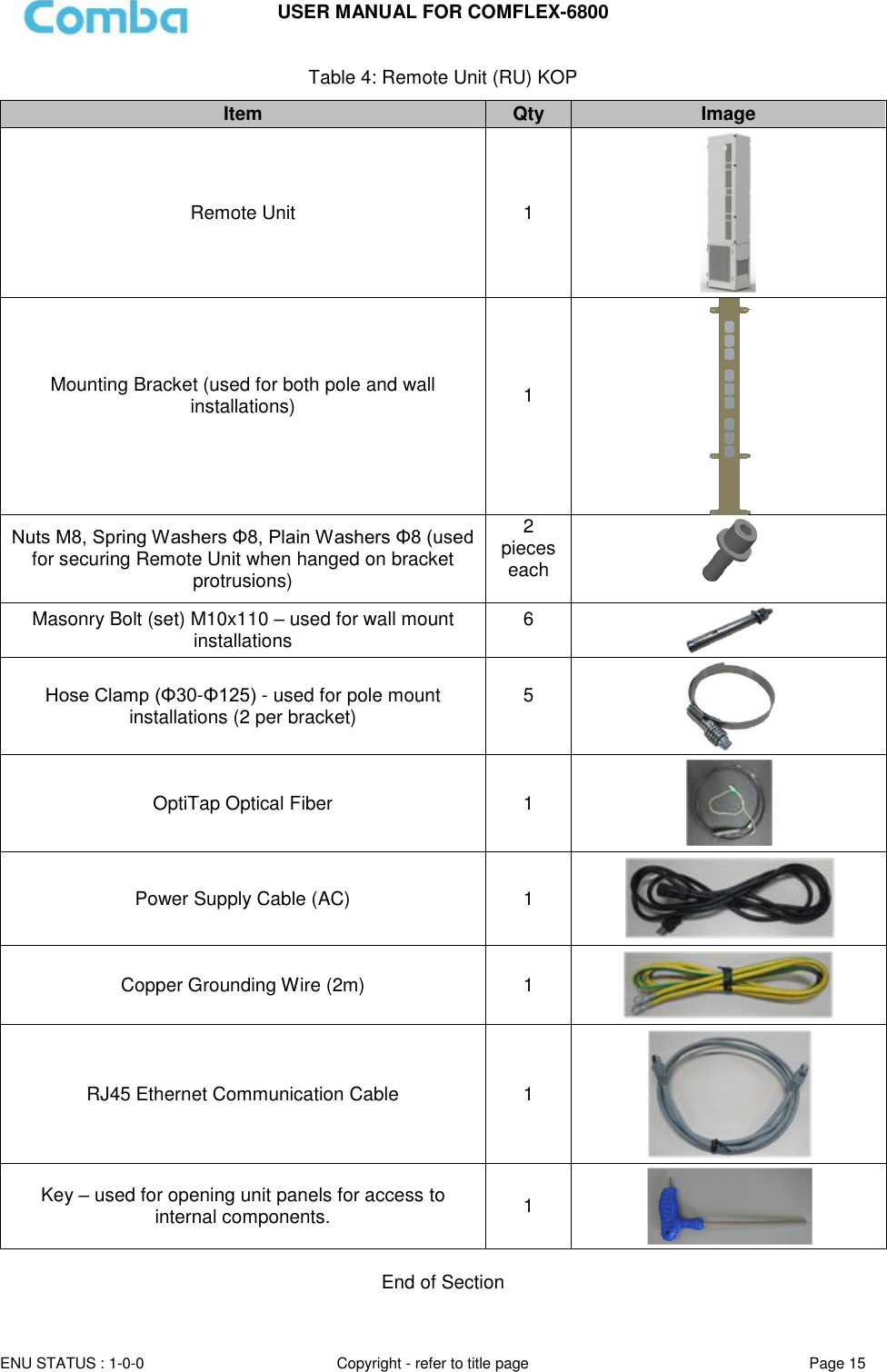
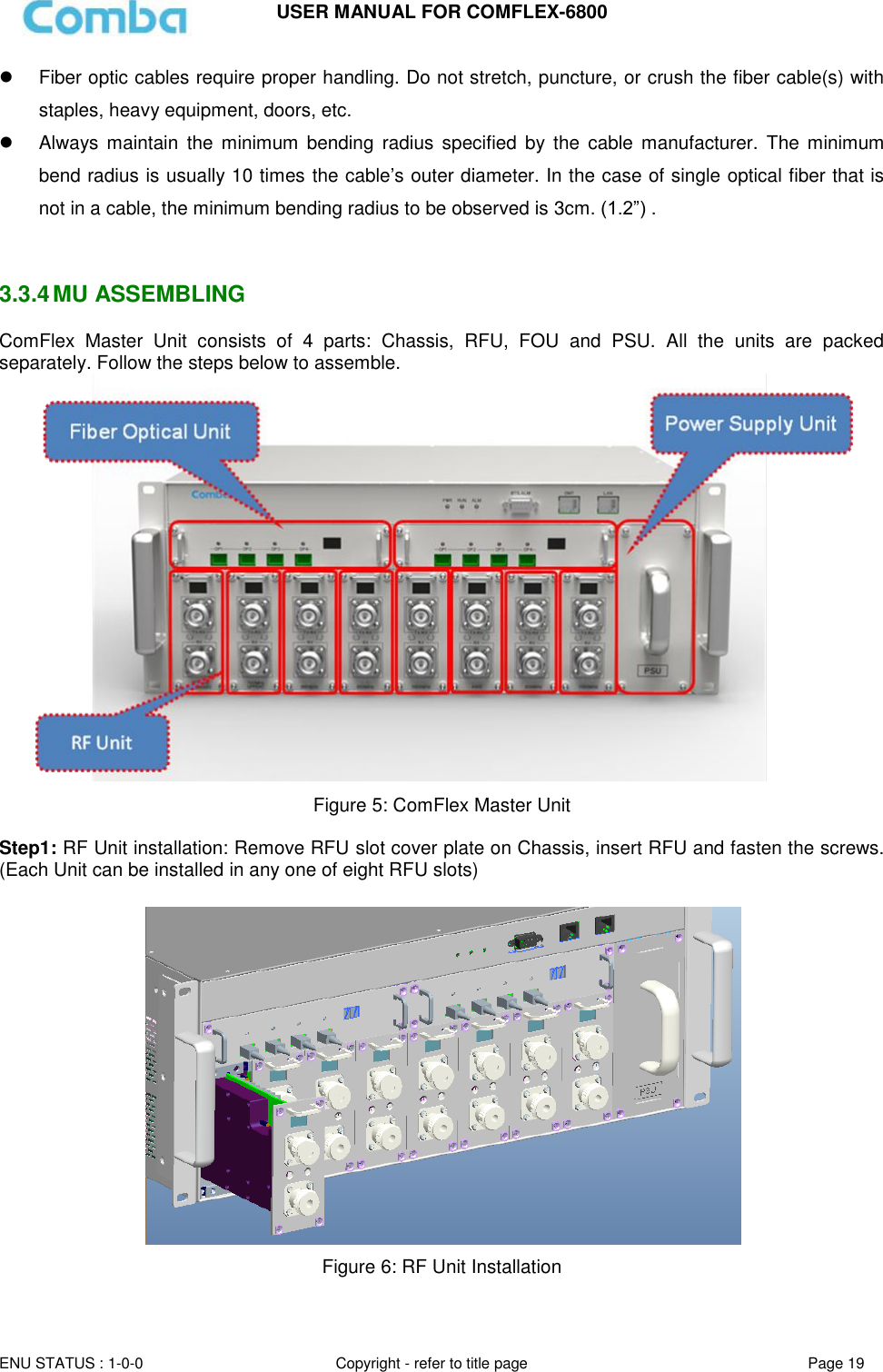
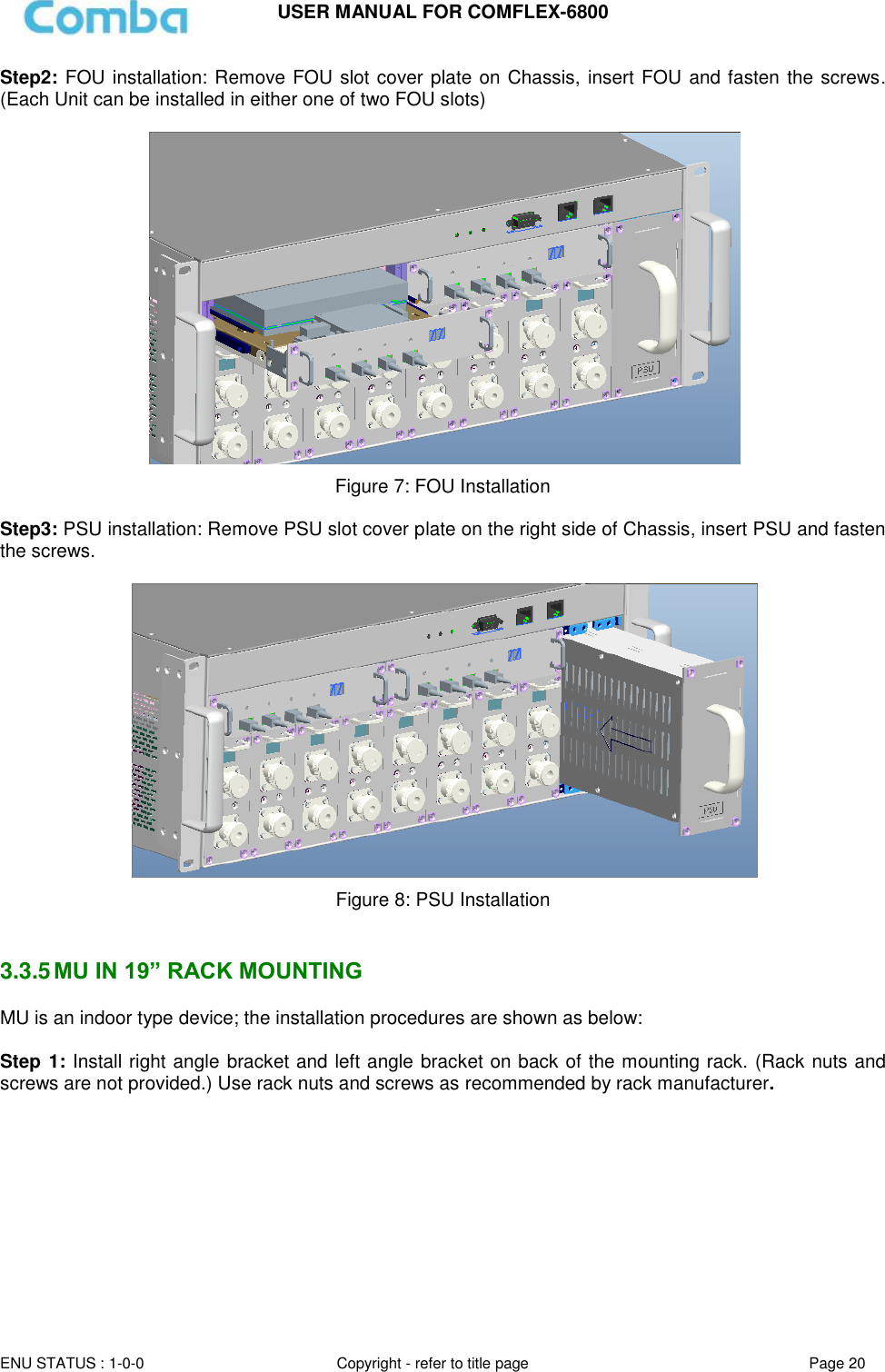
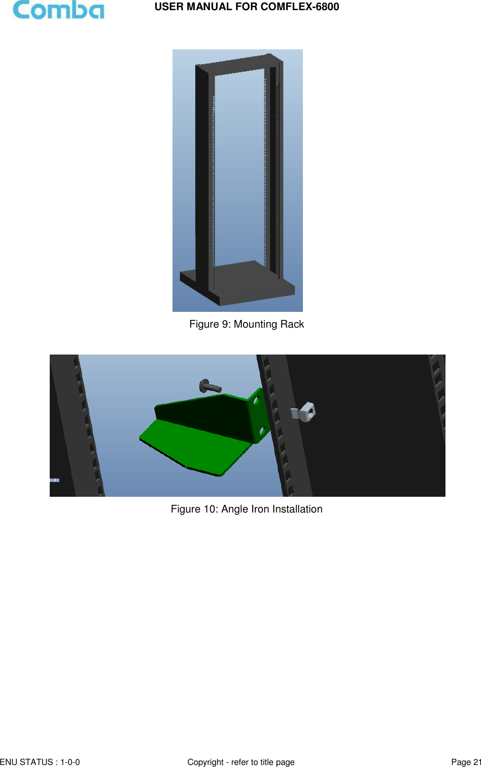
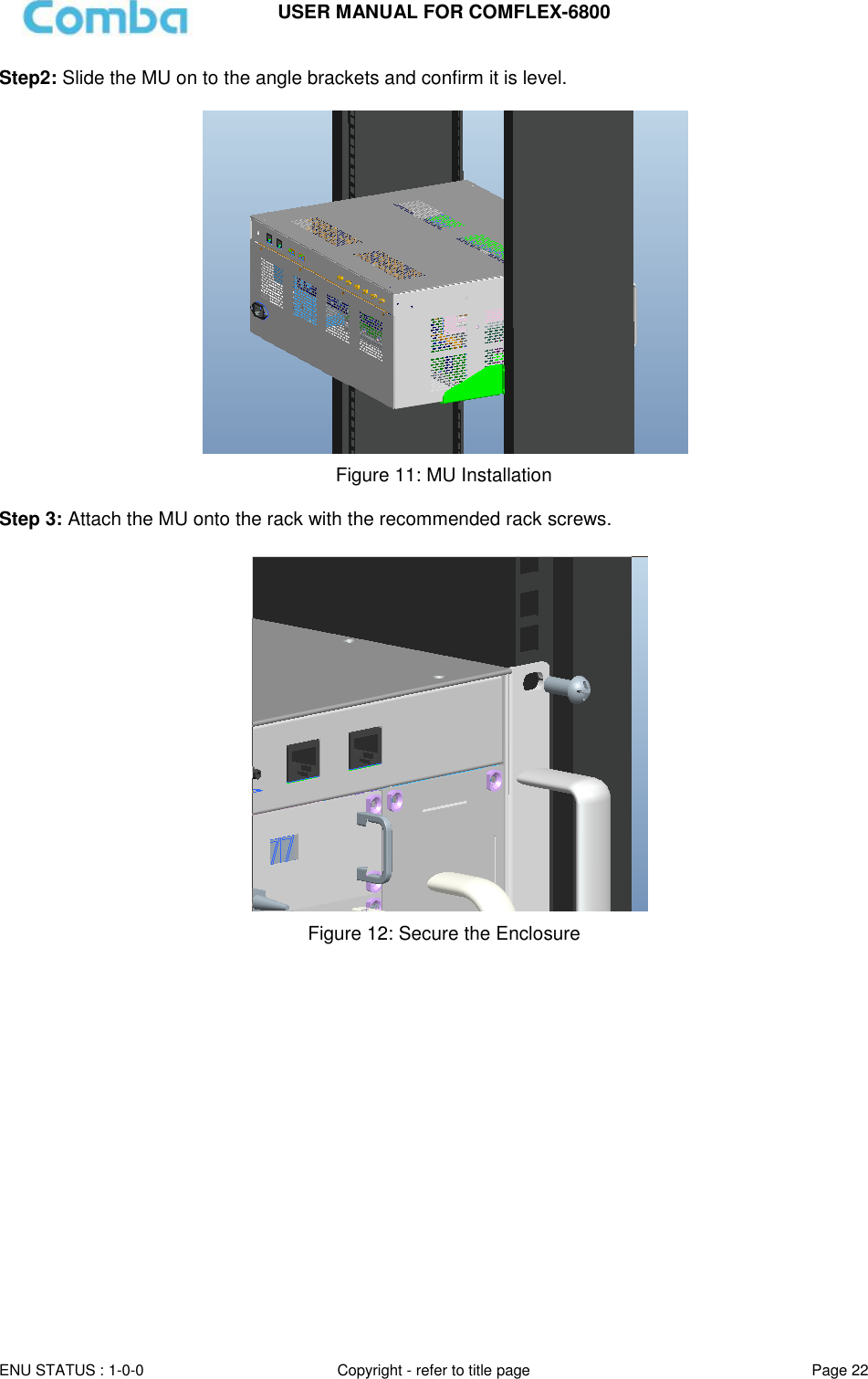
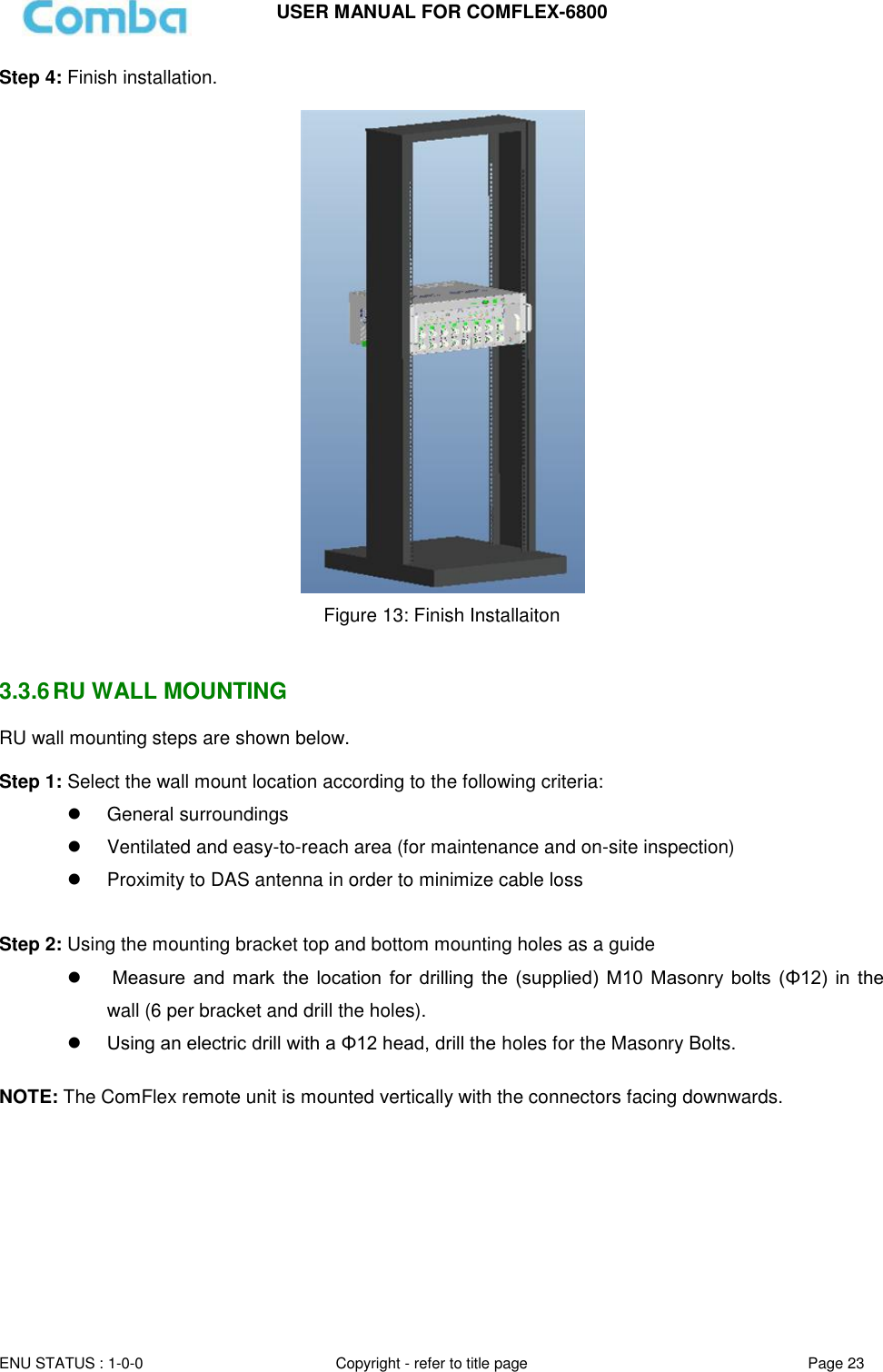
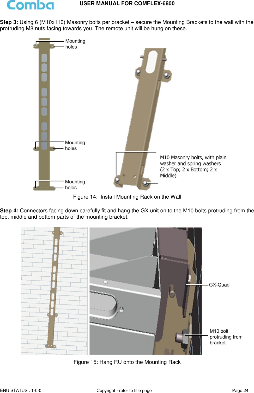
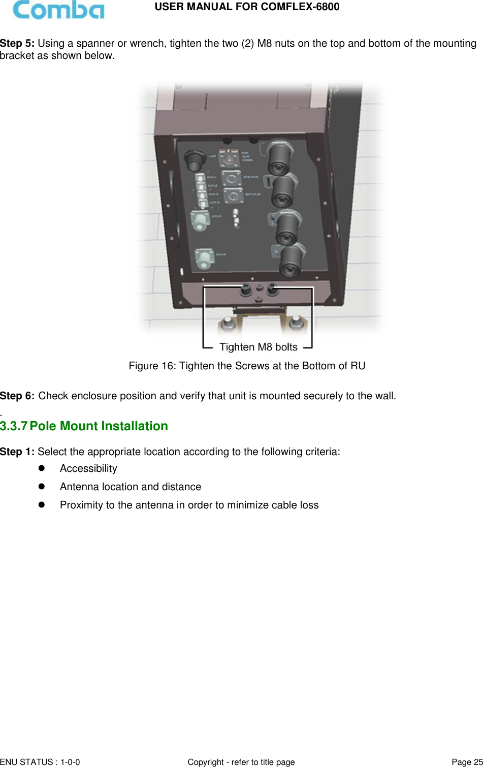
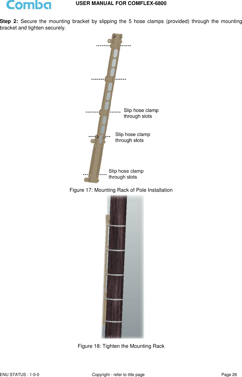
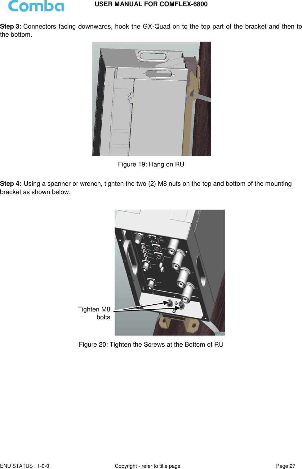
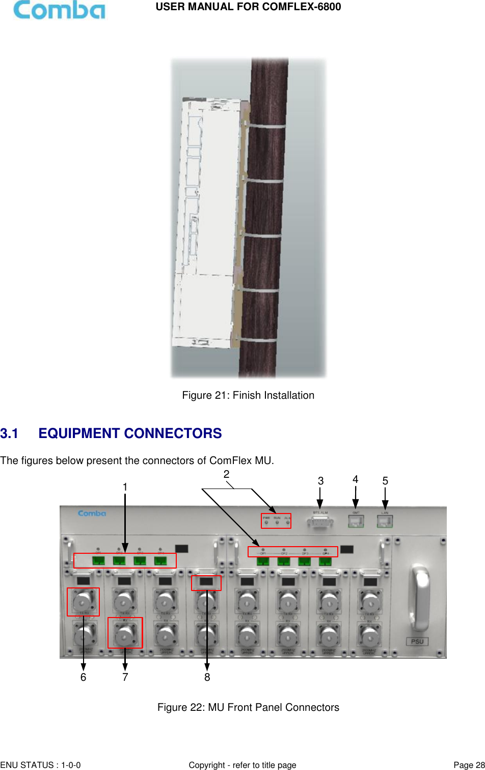
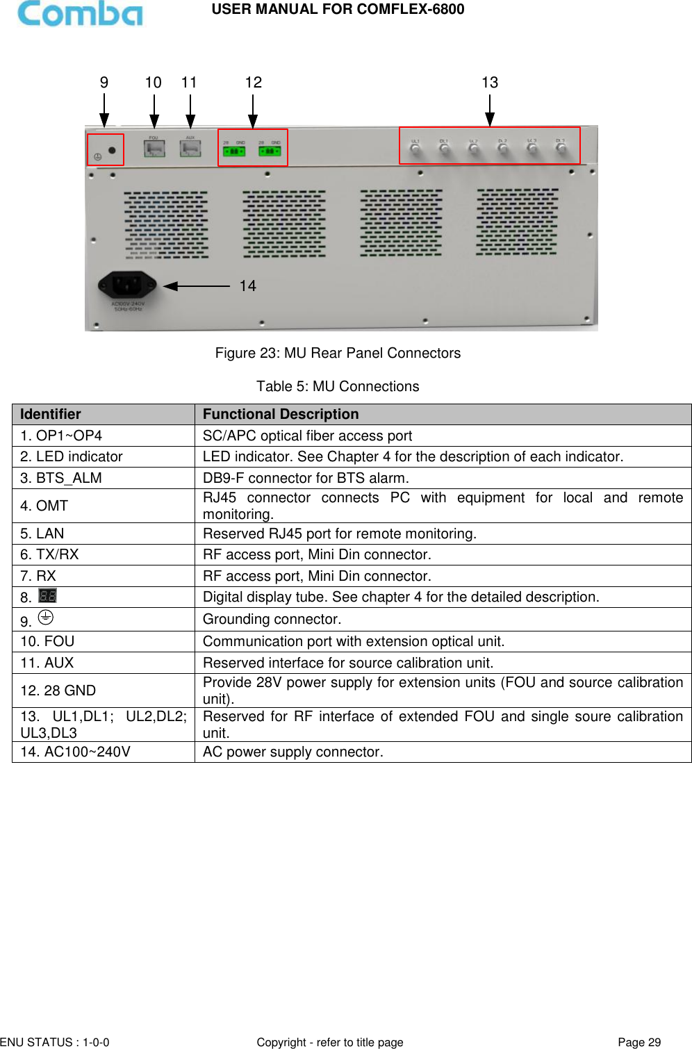
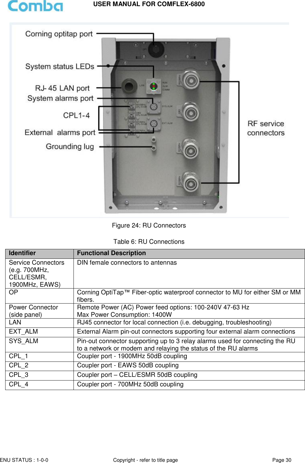
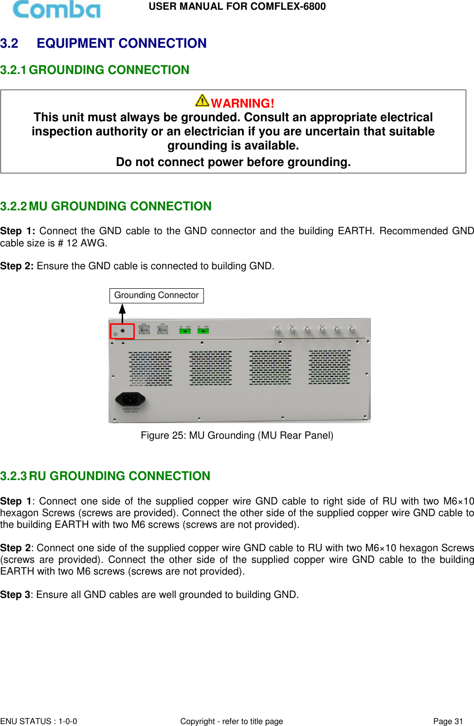
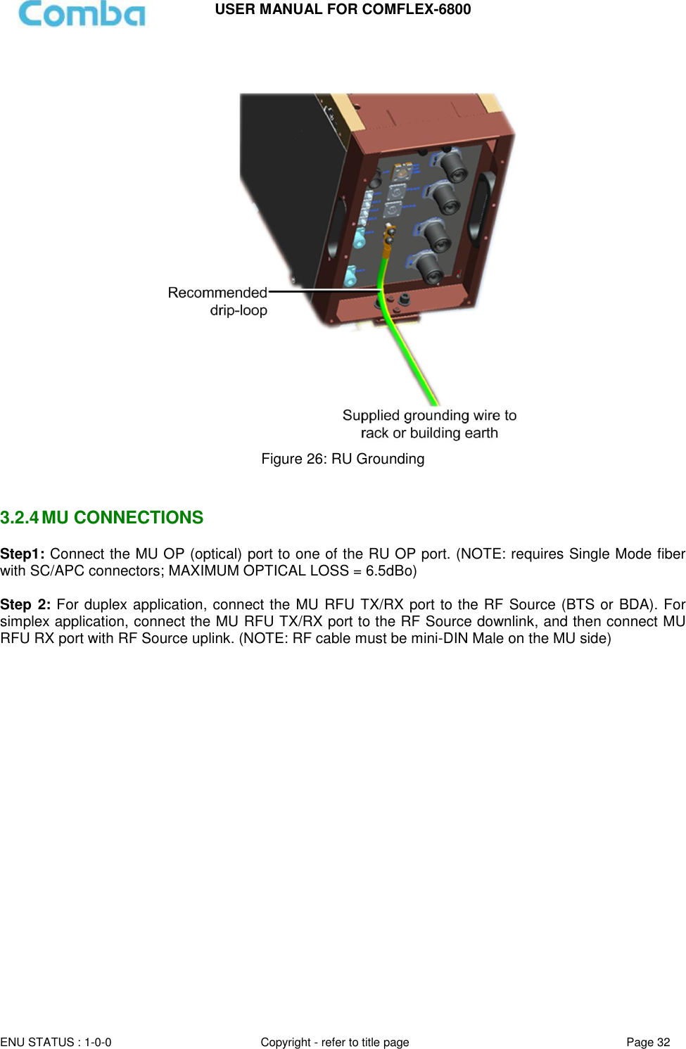
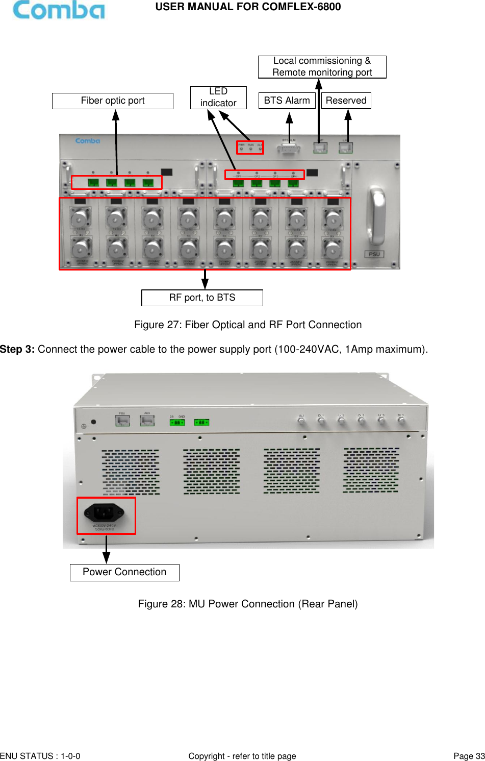
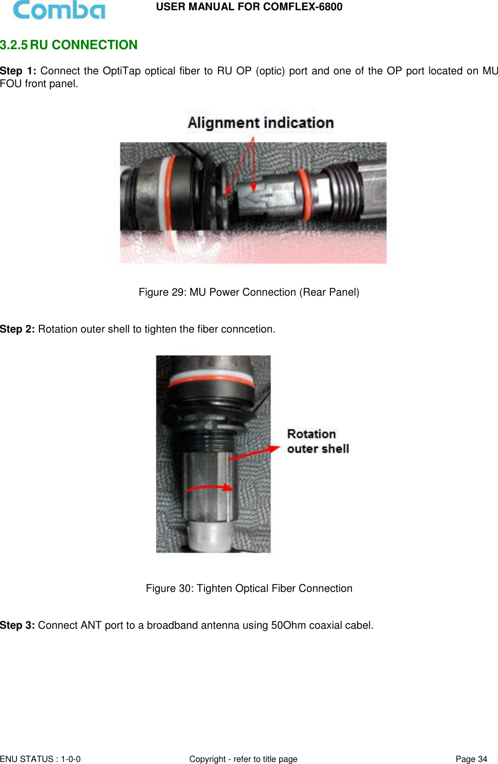
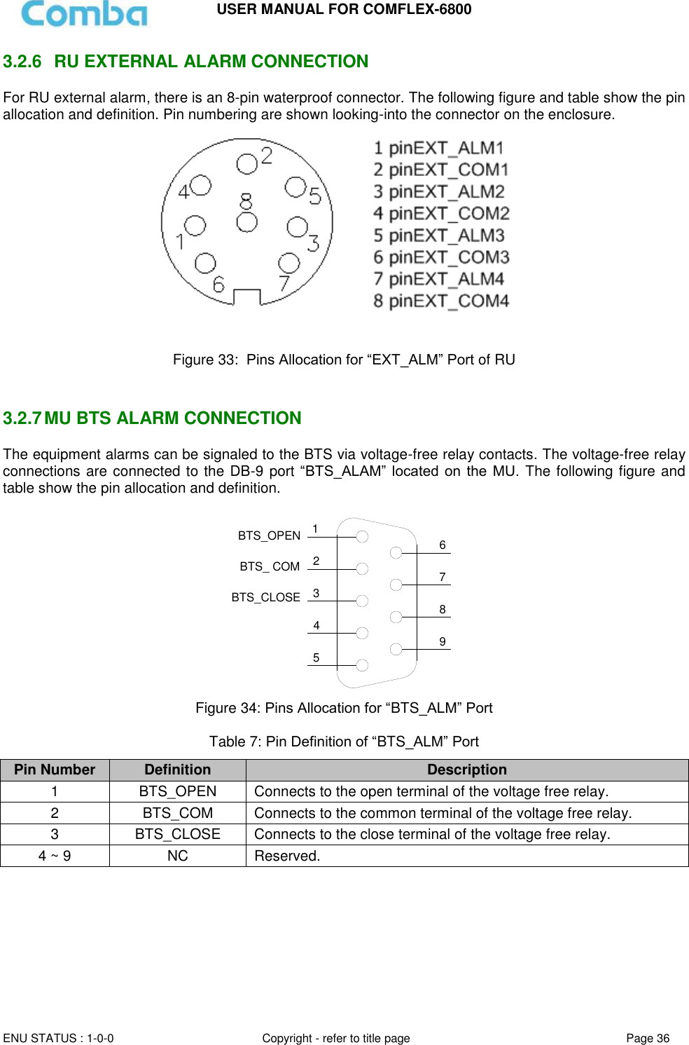
![USER MANUAL FOR COMFLEX-6800 ENU STATUS : 1-0-0 Copyright - refer to title page Page 5 0.2 INDEX TO FIGURES AND TABLES Figure 1: Master Unit (MU) ...................................................................................................................................... 10 Figure 2: Remote Unit (RU) ..................................................................................................................................... 11 Figure 3: System Diagramc ..................................................................................................................................... 12 Figure 4: Typical Application ................................................................................................................................... 12 Figure 5: ComFlex Master Unit ............................................................................................................................... 19 Figure 6: RF Unit Installation ................................................................................................................................... 19 Figure 7: FOU Installation ........................................................................................................................................ 20 Figure 8: PSU Installation ........................................................................................................................................ 20 Figure 9: Mounting Rack .......................................................................................................................................... 21 Figure 10: Angle Iron Installation ............................................................................................................................ 21 Figure 11: MU Installation ........................................................................................................................................ 22 Figure 12: Secure the Enclosure ............................................................................................................................ 22 Figure 13: Finish Installaiton ................................................................................................................................... 23 Figure 14: Install Mounting Rack on the Wall ...................................................................................................... 24 Figure 15: Hang RU onto the Mounting Rack ....................................................................................................... 24 Figure 16: Tighten the Screws at the Bottom of RU ............................................................................................ 25 Figure 17: Mounting Rack of Pole Installation ...................................................................................................... 26 Figure 18: Tighten the Mounting Rack................................................................................................................... 26 Figure 19: Hang on RU ............................................................................................................................................ 27 Figure 20: Tighten the Screws at the Bottom of RU ............................................................................................ 27 Figure 21: Finish Installation ................................................................................................................................... 28 Figure 22: MU Front Panel Connectors ................................................................................................................. 28 Figure 23: MU Rear Panel Connectors ................................................................................................................. 29 Figure 24: RU Connectors ....................................................................................................................................... 30 Figure 25: MU Grounding (MU Rear Panel) ......................................................................................................... 31 Figure 26: RU Grounding ......................................................................................................................................... 32 Figure 27: Fiber Optical and RF Port Connection ................................................................................................ 33 Figure 28: MU Power Connection (Rear Panel) ................................................................................................... 33 Figure 29: MU Power Connection (Rear Panel) ................................................................................................... 34 Figure 30: Tighten Optical Fiber Connection ........................................................................................................ 34 Figure 31: Power Supply Connection .................................................................................................................... 35 Figure 32: RU Fiber Optical and RF Port Connection ........................................................................................ 35 Figure 33: Pins Allocation for “EXT_ALM” Port of RU ........................................................................................ 36 Figure 34: Pins Allocation for “BTS_ALM” Port .................................................................................................... 36 Figure 35: RFU Digital Display ................................................................................................................................ 39 Figure 36: Optical Port No. and Digital Display .................................................................................................... 39 Figure 37: PC IP Address Setting........................................................................................................................... 41 Figure 38: Input IP Address ..................................................................................................................................... 41 Figure 39: Input User Name and Password .......................................................................................................... 42 Figure 40: Web GUI Main Screen .......................................................................................................................... 42 Figure 41: [Devices] Sceen ..................................................................................................................................... 43 Figure 40: MU Device - Monitoring Unit ................................................................................................................ 43 Figure 41: MU Device - Optical Unit ....................................................................................................................... 44 Figure 42: MU Device - RF Unit .............................................................................................................................. 44 Figure 43: RU Device ............................................................................................................................................... 45 Figure 44: RU Device – 700 .................................................................................................................................... 46 Figure 45: RU Device – External Alarm ................................................................................................................. 46 Figure 50: RU Device – Fan Alarm ........................................................................................................................ 47 Figure 46: [Commissioning] Screen ....................................................................................................................... 47 Figure 47: [Firmware] Screen – Modnitoring Upgade ......................................................................................... 48 Figure 48: [Firmware] Screen – Pop-up Window 1 .............................................................................................. 48 Figure 49: [Firmware] Screen – Pop-up Window 2 .............................................................................................. 48 Figure 50: [Firmware] Screen - Swap .................................................................................................................... 49 Figure 51: [Firmware] Screen – Module Upgrade ................................................................................................ 49](https://usermanual.wiki/Comba-Telecom/HRU01-6800/User-Guide-3343015-Page-7.png)
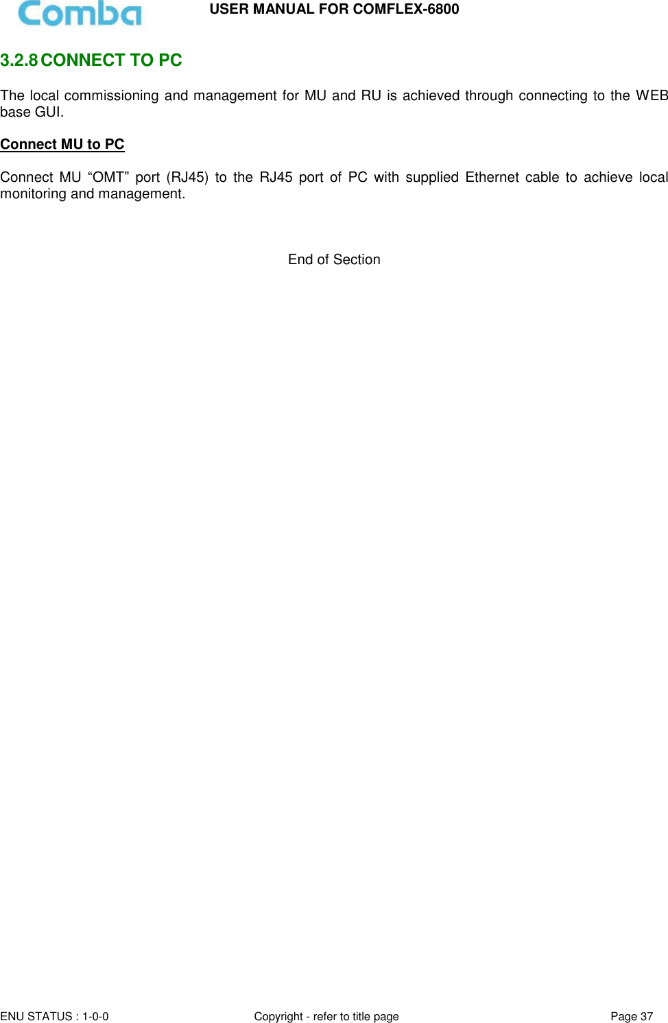
![USER MANUAL FOR COMFLEX-6800 ENU STATUS : 1-0-0 Copyright - refer to title page Page 6 Figure 52: [Management] Sceen ............................................................................................................................ 50 Figure 53: Management – Import&Export ............................................................................................................. 51 Figure 54: Management – IP Setting ..................................................................................................................... 52 Figure 55: Management – SNMP Setting.............................................................................................................. 52 Figure 56: Management – Security ........................................................................................................................ 53 Figure 57: Modify Password .................................................................................................................................... 53 Figure 58: Management – Device Reset ............................................................................................................... 54 Figure 59: Management – PA Reset ...................................................................................................................... 54 Figure 60: Management – Device Info ................................................................................................................... 55 Figure 61: Management – Device Scanning ......................................................................................................... 55 Figure 62: Management – Device Remove .......................................................................................................... 56 Figure 63: Management – Report........................................................................................................................... 57 Figure 67: Firefox setting (1) ................................................................................................................................... 57 Figure 65: Firefox setting (2) ................................................................................................................................... 58 Figure 66: Management – Alarm Log .................................................................................................................... 59 Figure 67: Commissioning Procedure - Start........................................................................................................ 60 Figure 68: Commissioning Procedure – Device Scan ......................................................................................... 60 Figure 69: Commissioning Procedure – Params Setting .................................................................................... 61 Figure 70: Dev Info & Date/Time ............................................................................................................................ 61 Figure 71: Commissioning Procedure – MU Calibration ..................................................................................... 62 Figure 72: Commissioning Procedure – MU Calibration Finish ......................................................................... 62 Figure 73: Commissioning Procedure – RU Calibration ..................................................................................... 63 Figure 74: Commissioning Procedure – RU Calibration Finish .......................................................................... 63 Figure 75: Commissioning Procedure – MU Setup ............................................................................................. 64 Figure 76: MU Frequency Band Table ................................................................................................................... 64 Figure 77: Commissioning Procedure – RU Setup .............................................................................................. 65 Figure 78: RU Frequency Band Table ................................................................................................................... 65 Figure 79: Commissioning Procedure – Finish .................................................................................................... 66 Table 1: MU Components ........................................................................................................................................ 13 Table 2: RU Components ........................................................................................................................................ 13 Table 3: Master Unit (MU) KOP .............................................................................................................................. 14 Table 4: Remote Unit (RU) KOP ............................................................................................................................ 15 Table 5: MU Connections ........................................................................................................................................ 29 Table 6: RU Connections ......................................................................................................................................... 30 Table 8: Pin Definition of “BTS_ALM” Port............................................................................................................ 36 Table 9: MU LED Indications .................................................................................................................................. 38 Table 10: RU LED Indications ................................................................................................................................. 38 Table 11: RFU Digital Display ................................................................................................................................. 39 Table 12: FOU Digital Display ................................................................................................................................. 40 Table 13: Import/Export Parameters ...................................................................................................................... 51 Table 14: MU Alarm List .......................................................................................................................................... 67 Table 15: RU Alarm List ........................................................................................................................................... 67 Table 16: MU Alarms Diagnosis ............................................................................................................................. 68 Table 17: RU Alarms Diagnosis .............................................................................................................................. 68](https://usermanual.wiki/Comba-Telecom/HRU01-6800/User-Guide-3343015-Page-8.png)
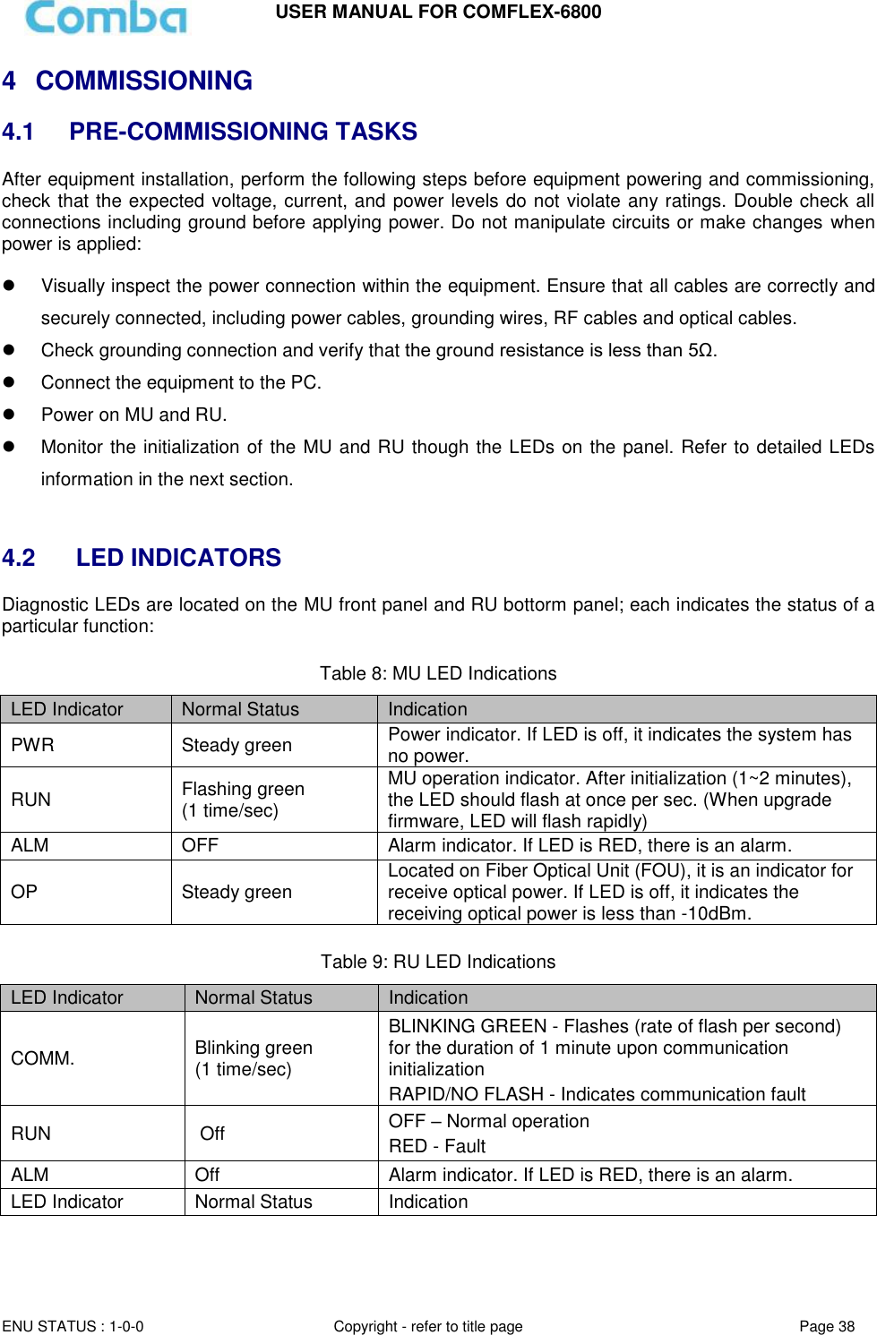
![ENU STATUS : 1-0-0 Copyright - refer to title page Page 41 Page 4141 5 WEB GUI ComFlex can be monitored and controlled by WEB GUI, follow below contents to achive system parameter setting and commissioning. 5.1 WEB GUI CONNECTION Step 1: Connect MU OMT port to PC RJ45 port with the supplied Ethernet cable to set up a physical connection. Step 2: Go to laptop Control Panel\Network and Internet\Local Area Connection. Right click it and click Properties. Then follow the steps shown in figure below. Figure 37: PC IP Address Setting Step 3: Open browser (browser IE7.0, IE8.0, Chrome or Firefox, suggest disply resolution is 1024×768), input Web GUI IP address: 192.168.8.101, click [Enter]. Figure 38: Input IP Address Step 2: Input User Name: admin; Password (default password: admin). Click [Log in].](https://usermanual.wiki/Comba-Telecom/HRU01-6800/User-Guide-3343015-Page-43.png)
![USER MANUAL FOR COMFLEX-6800 ENU STATUS : 1-0-0 Copyright - refer to title page Page 42 Figure 39: Input User Name and Password 5.2 WEB GUI INTRODUCTION After login, the Web GUI main screen will appear. Figure 40: Web GUI Main Screen On Comba Web GUI Home page, there are four Menu bars: [Devices], Commissioning], [Firmware] and [Management]. 5.2.1 [DEVICES] The [Devices] page shows the actual connection diagram of MU and RU.](https://usermanual.wiki/Comba-Telecom/HRU01-6800/User-Guide-3343015-Page-44.png)
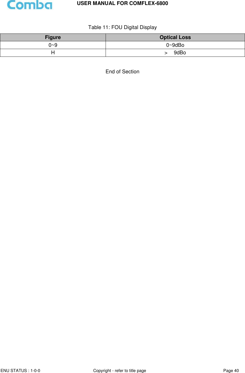
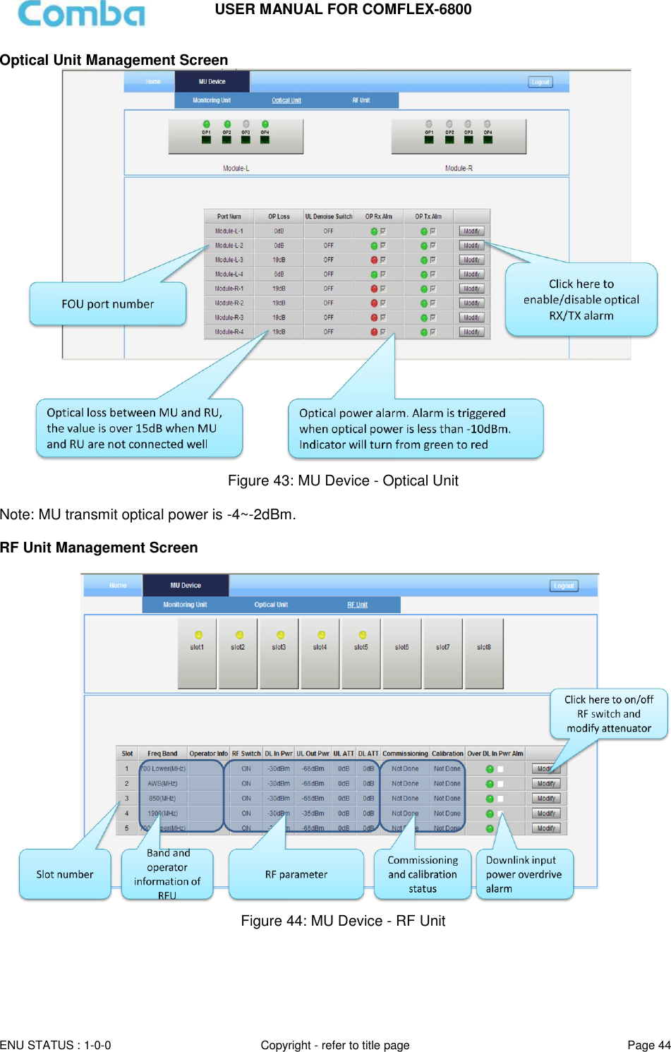
![USER MANUAL FOR COMFLEX-6800 ENU STATUS : 1-0-0 Copyright - refer to title page Page 43 Figure 41: [Devices] Sceen MU Main Management Screen Figure 42: MU Device - Monitoring Unit](https://usermanual.wiki/Comba-Telecom/HRU01-6800/User-Guide-3343015-Page-45.png)
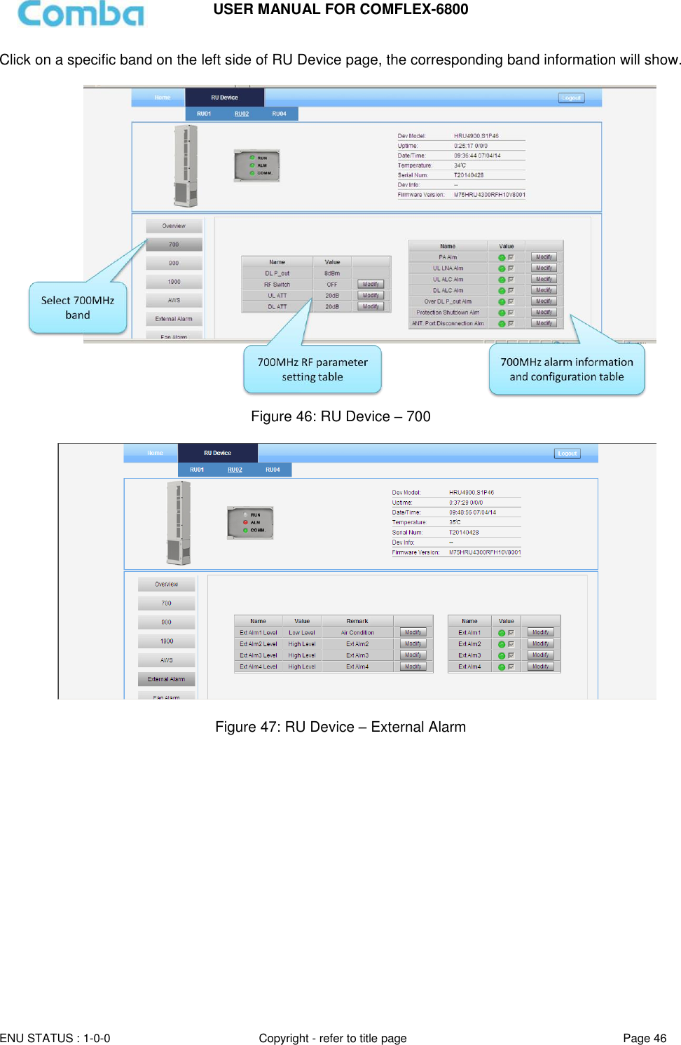
![USER MANUAL FOR COMFLEX-6800 ENU STATUS : 1-0-0 Copyright - refer to title page Page 45 Remote Unit Management Screen Click RU photo, users can visit RU directly. Make sure two steps are done before visit RU: RU and MU are connected by optical fiber. RU device scanning is done. Note: Go to [Commissioning] page or [Management] page for device scanning. Figure 45: RU Device NOTE: There are three statuses for PA Service: Normal, Recovery and Shutdown. If PA output power or reflected power exceeds the threshold (48dBm), software will trigger Recovery: It will reset PA and then re-detect the PA output power and reflected power, if they are normal, the PA Service Status will turn to Normal, if PA output power or reflected power is still over the threshold, PA Service Status will turn to Recovery again. If PA output power or reflected power is still over the threshold after six times of PA Recovery, PA Service status will be Shutdown which will need to be reset manually. Reset at Management > PA Reset.](https://usermanual.wiki/Comba-Telecom/HRU01-6800/User-Guide-3343015-Page-47.png)
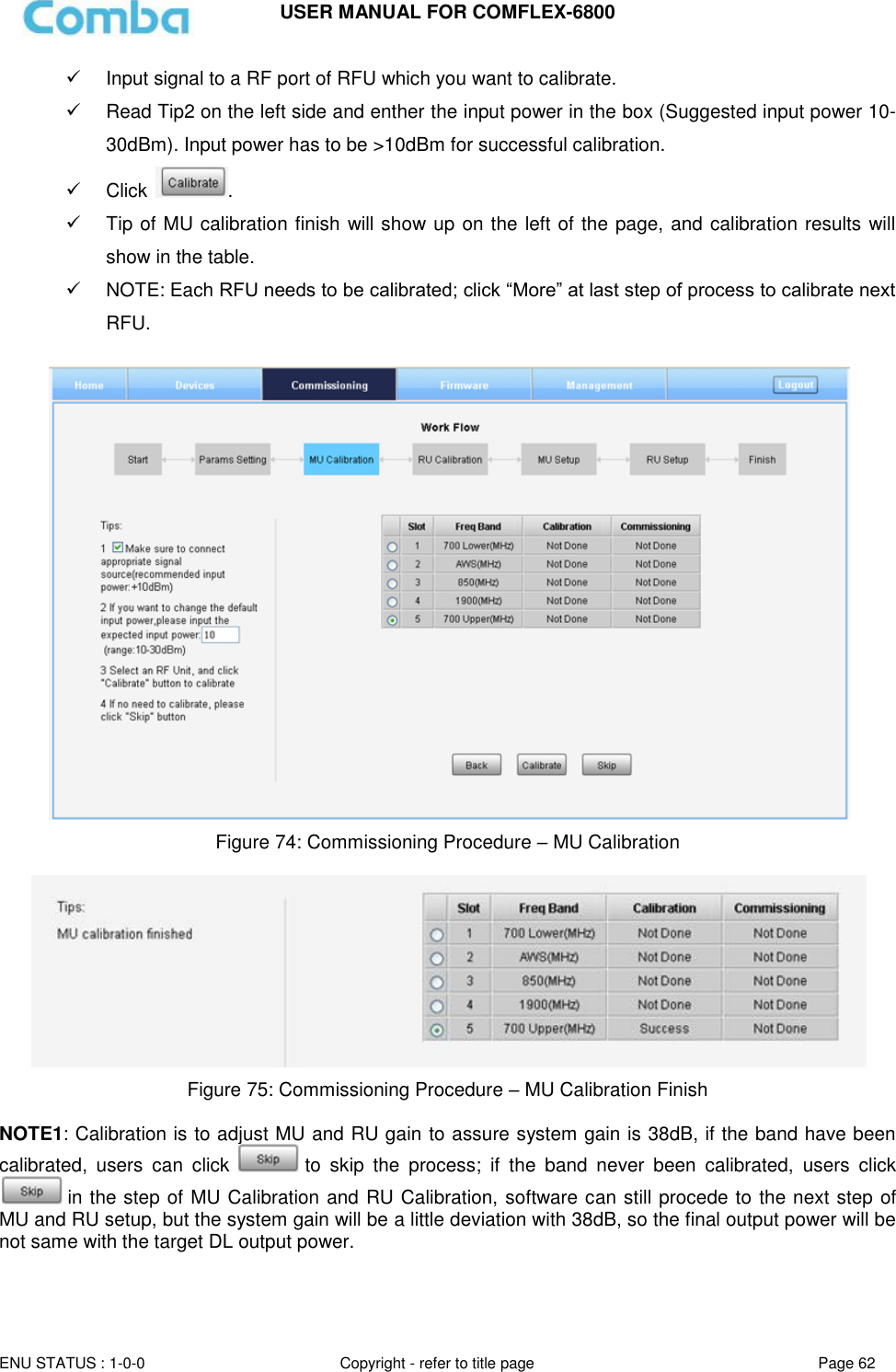
![USER MANUAL FOR COMFLEX-6800 ENU STATUS : 1-0-0 Copyright - refer to title page Page 47 Figure 48: RU Device – Fan Alarm 5.2.2 [COMMISSIONING] A work flow of the commissioning process is shown on [Commissioning] page. Click the [Start] button, the software will guide you through the commissioning step by step. For details, please refer to chapter 5.3. Figure 49: [Commissioning] Screen 5.2.3 [FIRMWARE] There are three functions on the [Firmware] bar: [Monitoring Upgrade], [Swap] and [Module Upgrade]. [Monitoring Upgrade] is used to upgrade MCU software, [Swap] is to replace current MCU firmware version to the previous one, [Module Upgrade] is to upgrade software of each module.](https://usermanual.wiki/Comba-Telecom/HRU01-6800/User-Guide-3343015-Page-49.png)
![USER MANUAL FOR COMFLEX-6800 ENU STATUS : 1-0-0 Copyright - refer to title page Page 48 Follow steps shown in below figure to upgrade MCU firmware. Figure 50: [Firmware] Screen – Modnitoring Upgade Step 4: After clicking , a window will pop up and click . Figure 51: [Firmware] Screen – Pop-up Window 1 Step 5: Wait for 2~4 minutes while MU/RU is being reset. Figure 52: [Firmware] Screen – Pop-up Window 2 Step1:select deviceStep2:Click to select software that to be updatedStep3:Click to upgrade software](https://usermanual.wiki/Comba-Telecom/HRU01-6800/User-Guide-3343015-Page-50.png)
![USER MANUAL FOR COMFLEX-6800 ENU STATUS : 1-0-0 Copyright - refer to title page Page 49 Step 6: Clear browsing history and cookies from browser. NOTE: For MU software upgrade, users need to re-login Web GUI after reset is done. Follow steps shown in below figure to Swap MCU firmware. Figure 53: [Firmware] Screen - Swap Follow steps shown in below figure to upgrade module firmware. Figure 54: [Firmware] Screen – Module Upgrade Step1:select deviceStep2:Click to swap firmware to previous versionStep1:select deviceStep2:Click to select software that to be updatedStep3:Click to upgrade software](https://usermanual.wiki/Comba-Telecom/HRU01-6800/User-Guide-3343015-Page-51.png)
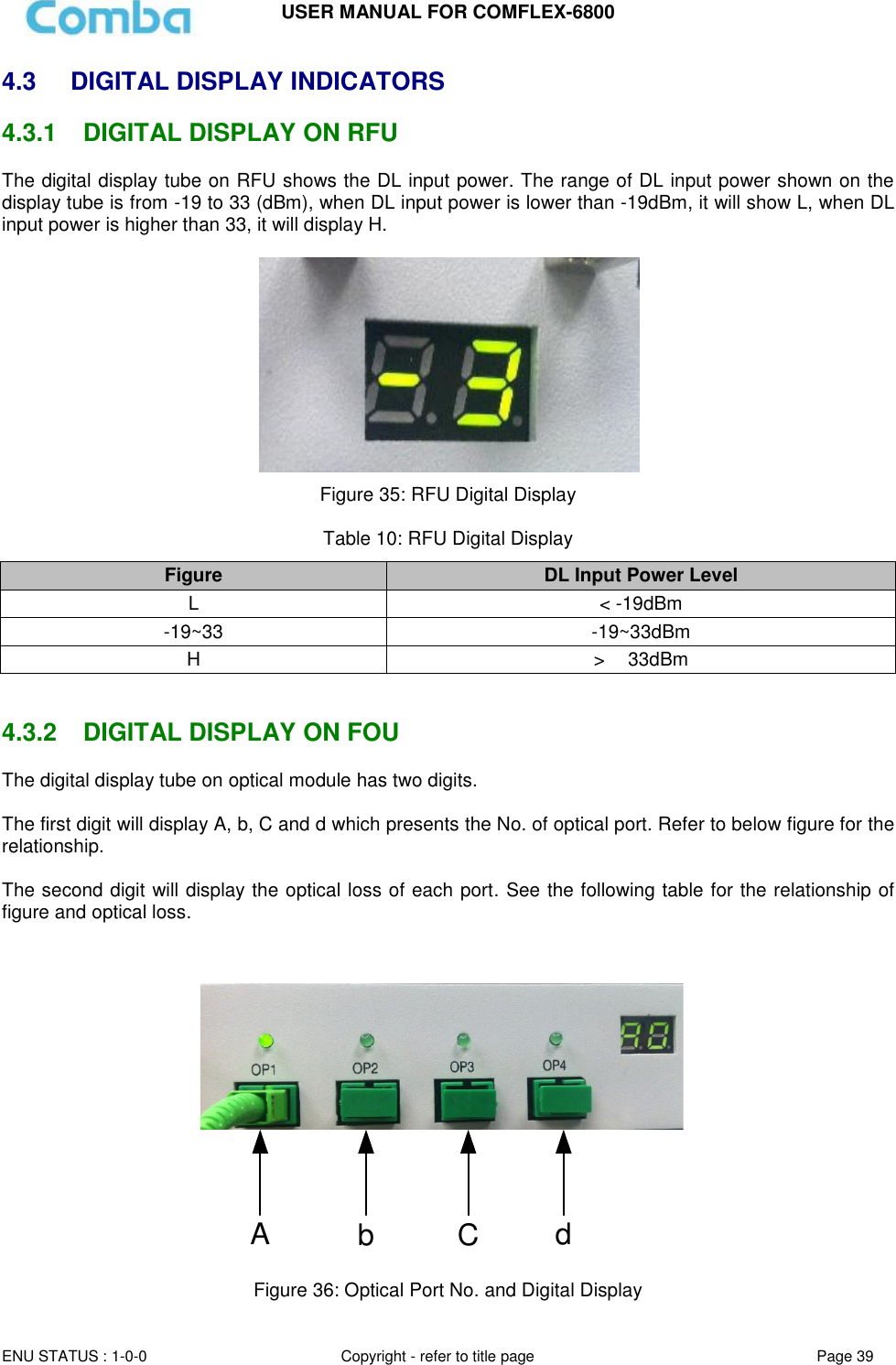
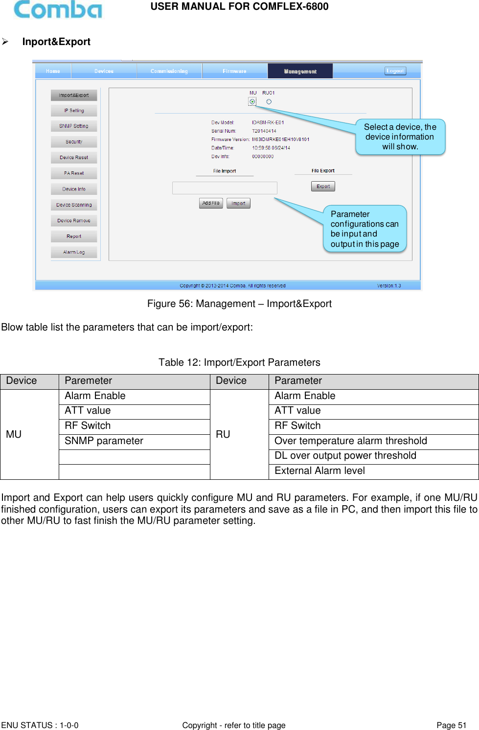
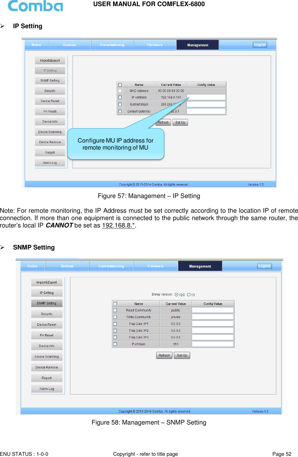
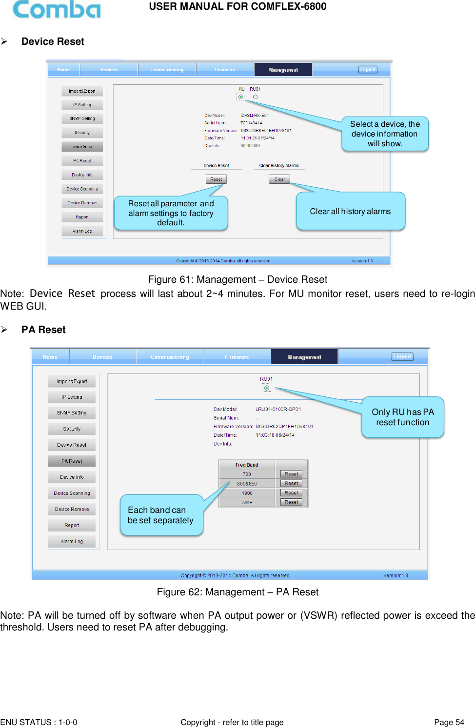
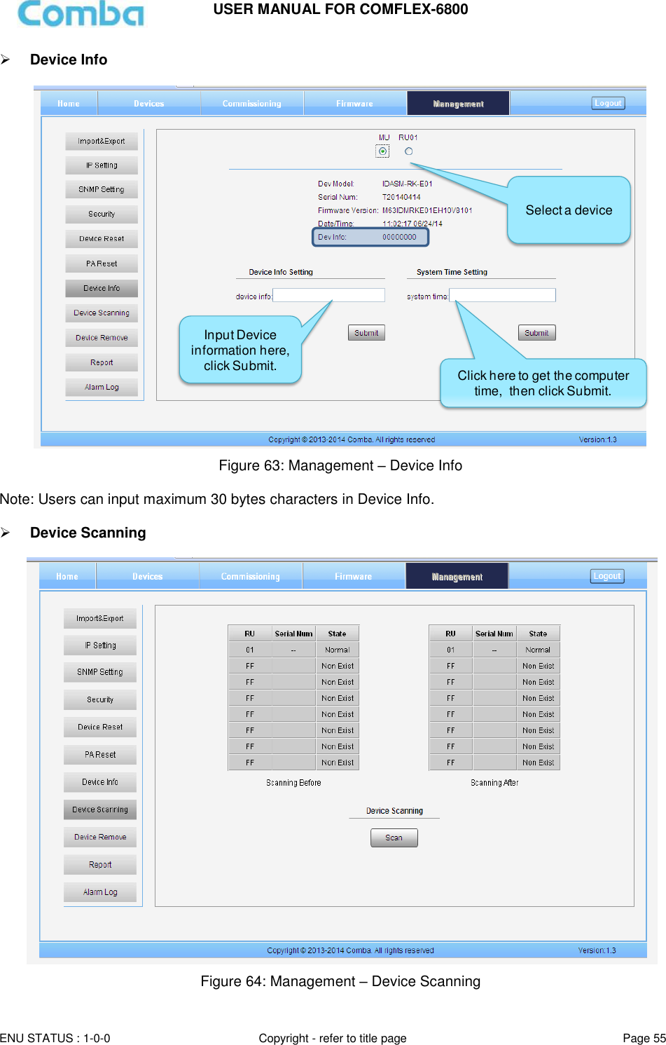
![USER MANUAL FOR COMFLEX-6800 ENU STATUS : 1-0-0 Copyright - refer to title page Page 50 Note 1: There are two loctiaons for Optical module – Module-L which is on the left and Module-R which is on the right side of MU. Note 2: FSK module is in side Optical modul. Noet 3: Adapter Module means RF module, [Slot] in the Adapter Module software upgrade table refers to the 8 slost on the MU Rack and the series number is from left to right. 5.2.4 [MANAGEMENT] Other parameters can be configured on [Management] page. Figure 55: [Management] Sceen There are nine function bar lised in the left side of the [Mangement] page. Below figures are the introduction of each function bar. Clink here to enter the corresponding page](https://usermanual.wiki/Comba-Telecom/HRU01-6800/User-Guide-3343015-Page-52.png)
![USER MANUAL FOR COMFLEX-6800 ENU STATUS : 1-0-0 Copyright - refer to title page Page 53 Security Figure 59: Management – Security Click , [Modify Password] window will pop-up. Figure 60: Modify Password Note: Username cannot be modified.](https://usermanual.wiki/Comba-Telecom/HRU01-6800/User-Guide-3343015-Page-55.png)
![USER MANUAL FOR COMFLEX-6800 ENU STATUS : 1-0-0 Copyright - refer to title page Page 56 Note: This Step is the same as step1 of [Commissioning]. Running scanning, software will allocate an ID to RU so that MU can identify and visit it. Device Remove Figure 65: Management – Device Remove Note: If the RU has been scanned and identified by MU, to remove the RU from the system,users must remove this RU on this [Device Remove] page, otherwise, RU will still be shown on the Home page and will trigger optical alarm.](https://usermanual.wiki/Comba-Telecom/HRU01-6800/User-Guide-3343015-Page-58.png)
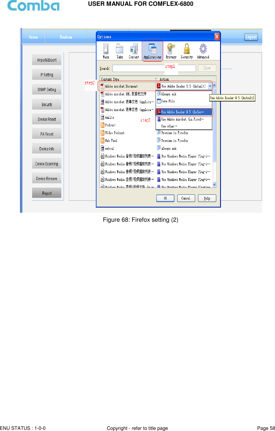
![USER MANUAL FOR COMFLEX-6800 ENU STATUS : 1-0-0 Copyright - refer to title page Page 57 Report Users can check the current running status of MU/RU by [Report] function. Figure 66: Management – Report Note: Users can use Chrome and Firefox to review the report. When using Chrome, once you click [Create], the report will be pop-up in a new window. When using Firefox as the browser, users need to set browser applications settings first, then follow the steps shown on the figure above to create the report. Figure 67: Firefox setting (1) Step 1: Select a deviceStep 2: Click [Create] to review the Report](https://usermanual.wiki/Comba-Telecom/HRU01-6800/User-Guide-3343015-Page-59.png)
![USER MANUAL FOR COMFLEX-6800 ENU STATUS : 1-0-0 Copyright - refer to title page Page 59 Alarm Log In [Alarm Log] page, users can query and export MU and RU history alarms, for facilitating trobuble shouting and monitoring MU/RU alarms. Figure 69: Management – Alarm Log Step 1: Select a device Step 2: Click to select a begin date and End dateStep 3: Click [Query] to review the log and click [ Export] to load the log on your computer](https://usermanual.wiki/Comba-Telecom/HRU01-6800/User-Guide-3343015-Page-61.png)
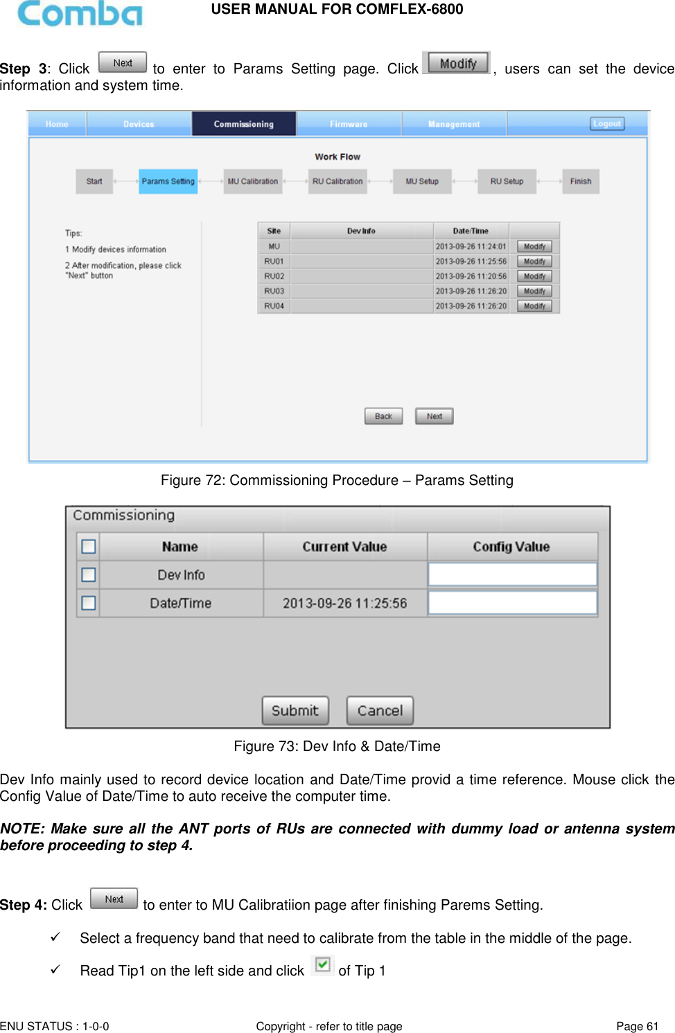
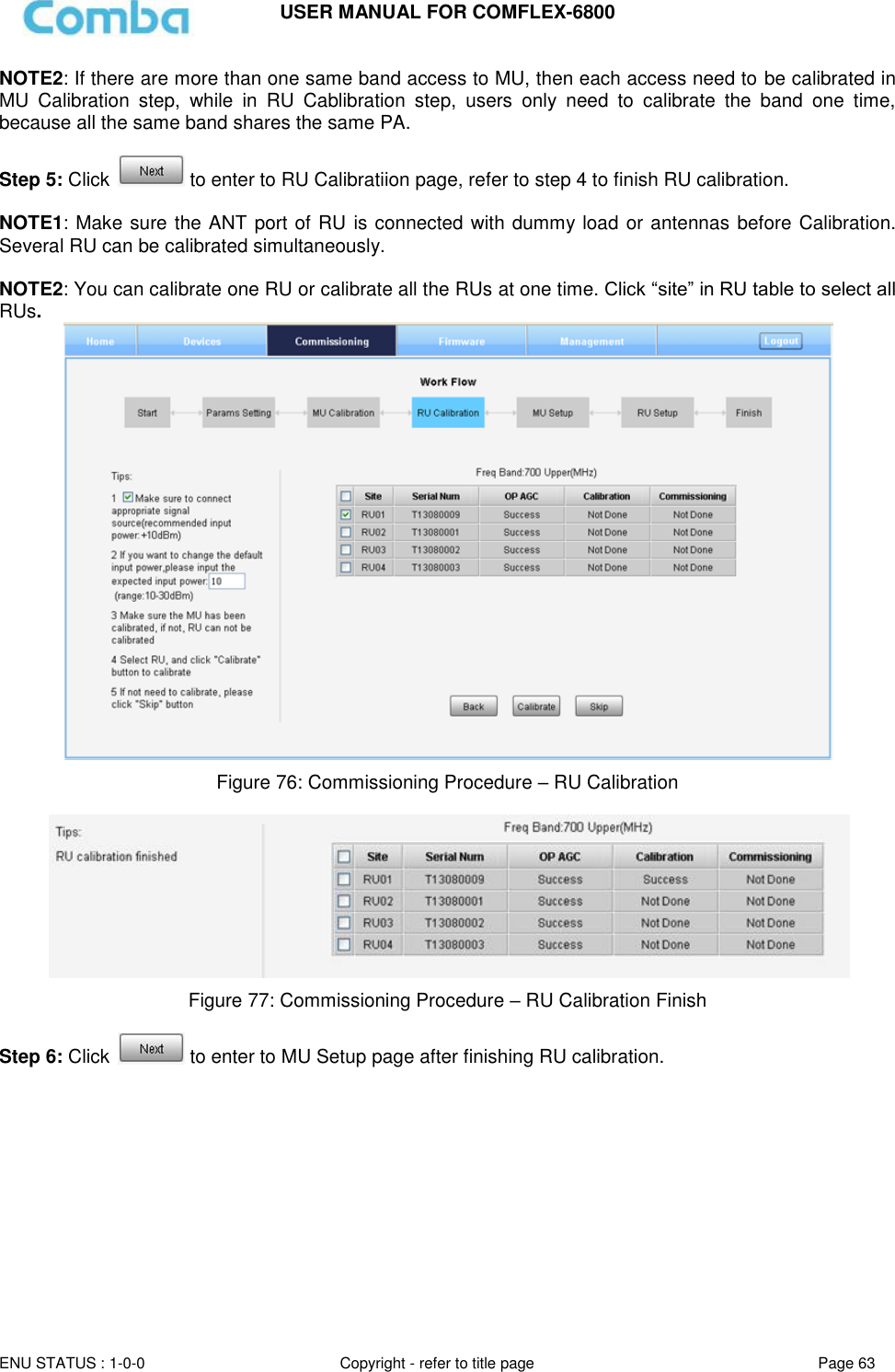
![USER MANUAL FOR COMFLEX-6800 ENU STATUS : 1-0-0 Copyright - refer to title page Page 60 5.3 COMMISSIONING PROCEDURE To complete the installation and commissioning, users need to follow the steps below. Step 1: Click Menu bar [Commissioning] on home page, a work flow will show up. Figure 70: Commissioning Procedure - Start Step 2: Click to start RU device scan, this step will take about 1 minute. Figure 71: Commissioning Procedure – Device Scan](https://usermanual.wiki/Comba-Telecom/HRU01-6800/User-Guide-3343015-Page-62.png)
![USER MANUAL FOR COMFLEX-6800 ENU STATUS : 1-0-0 Copyright - refer to title page Page 66 Step 8: Click to enter to [Finish] page after finishing RU setup. Click to calibrate other bands. Click if all bands’ clibration is done. Figure 82: Commissioning Procedure – Finish Note: As the system calibration process is calibrated for single channel, so if there is more than one same band input, because of the power superposition, the band total output power will higer than target DL output power after the calibration is complete. The calibration work is mainly to set device to reach it’s theoretical gain, so when there are two or more same bands access into and they have the same input power level, each channel will reach it’s rated power, so the total output power will be (input A+gain) + (inputB+gain)+…+(inputN+gain). For example, if there are two 1900MHz bands acess to MU, each has 10dBm input power, the total output power of RU 1900MHz will be 46dBm+46dBm=49dBm. For Multi-channel same band access, 800+850 (which share the same PA) access and 700 Uper C + LowerABC (also shared PA), they all will have power superposition. In this situation, users need to adjust system gain manually; otherwise, the output power will be higher than 48dBm which will trigger alarms (See Chapter 6 for details). Refer to the method below for the gain adjustment: Suppose a band with N independent inputs, each input signal power are all X dBm. Apparently, there exists the following relationship between input and output after finished auto communication on WEB GUI: X dBm + Gain = 46dBm, then the total output power for N channels access is X dBm + Gain + 10*Log(N) = 46 + 10*Log(N), so Users need to set 10*Log(N) RFU ATT on WEB GUI for each channel. End of Section](https://usermanual.wiki/Comba-Telecom/HRU01-6800/User-Guide-3343015-Page-68.png)
![USER MANUAL FOR COMFLEX-6800 ENU STATUS : 1-0-0 Copyright - refer to title page Page 68 Alarm judgment period: 3 minutes by default. 6.2 TROUBLESHOOTING Following installation and commissioning, occasional operation tasks to handle alarms may be required: Table 15: MU Alarms Diagnosis Alarm condition Diagnosis Over- Temperature alarm Check device temperature on WEB GUI If device temperature is over threshold, make sure environment temperature is within the envireonment temperature range that MU supported (0~40℃). Apply climatic protection to the system under severe environment. Optical TX Alarm Test MU transmit optical power Replace FOU if transmit optical power is less than -7dBm Optical RX Alarm Use Optical Power Meter to test received optical power If received optical power is lower than -10dBm, test whether RU transmit optical power is normal (3~5dBm) Check if optical loss of fiber link is higher than 6.5dBo Clean fiber connector with absolute ethanol DL Input Power Overload Alarm Test DL input power of MU, if it is higher than +33dBm, choose proper coupler to ensure the input power to MU is lower than +33dBm. Table 16: RU Alarms Diagnosis Alarm condition Diagnosis External Alarm Check to make sure if the external device connected is working normally Over- Temperature alarm Check device temperature on WEB GUI If device temperature e is over threshold, make sure environment temperature is within the envireonment temperature range that RU supported (-40~70℃).Apply climatic protection to the system under severe environment. Optical TX Alarm Test RU transmit optical power Replace FOU if transit optical power is less than 0dBm Optical RX Alarm Use Optical Power Meter to test received optical power If received optical power is lower than -14dBm, test whether MU transmit optical power is normal (-4~-2dBm) Check if optical loss of fiber link is higher than 6.5dBo Clean fiber connector with absolute ethanol DL PA alarms Check PA Service Status on WEB GUI RU page, If it is [Recovery], reset PA on WEB GUI Management page, then read RU output power: If output power is exceed threshold, need to reduce gain or input power; if output power is normall, check whether antenna port VSWR is too high. If it is [Shutdown], Refer to PA Shutdown Alram DL Output Power Overload Alarm Check if output power is exceed the threshold (48dBm) Decrease the gain to reduce the output power PA Shutdown Alarm Make Sure the environment temperature is -40~70℃ Reset PA, if PA service status turns to [Recovery], and then refer to DL PA](https://usermanual.wiki/Comba-Telecom/HRU01-6800/User-Guide-3343015-Page-70.png)