Comba Telecom MBDA-200 MBDA BAND SELECTIVE WIRELESS REPEATER User Manual
Comba Telecom Ltd. MBDA BAND SELECTIVE WIRELESS REPEATER
UserManual.wiki
>
Comba Telecom
>
MBDA 200 User Manual
User Manual
Navigation menu
Upload a User Manual
Namespaces
Wiki Guide
HTML
PDF
Info
Views
User Manual
Discussion / Help
Navigation
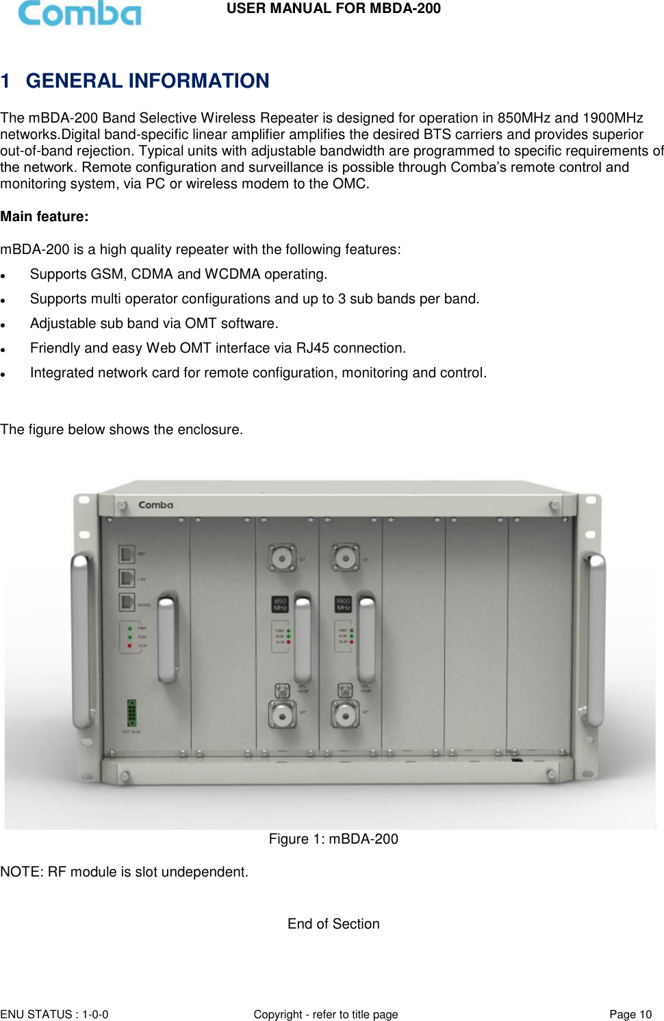
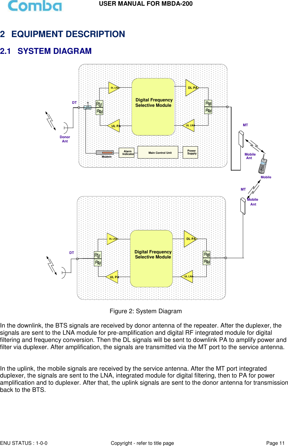
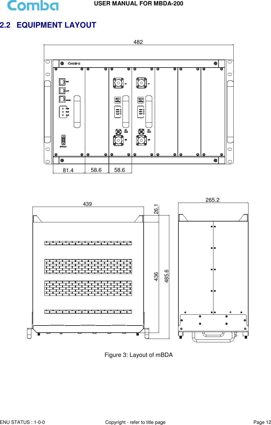
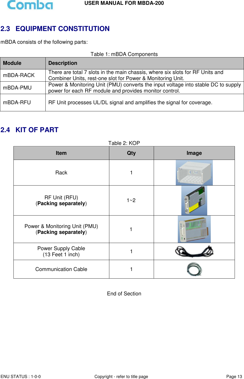
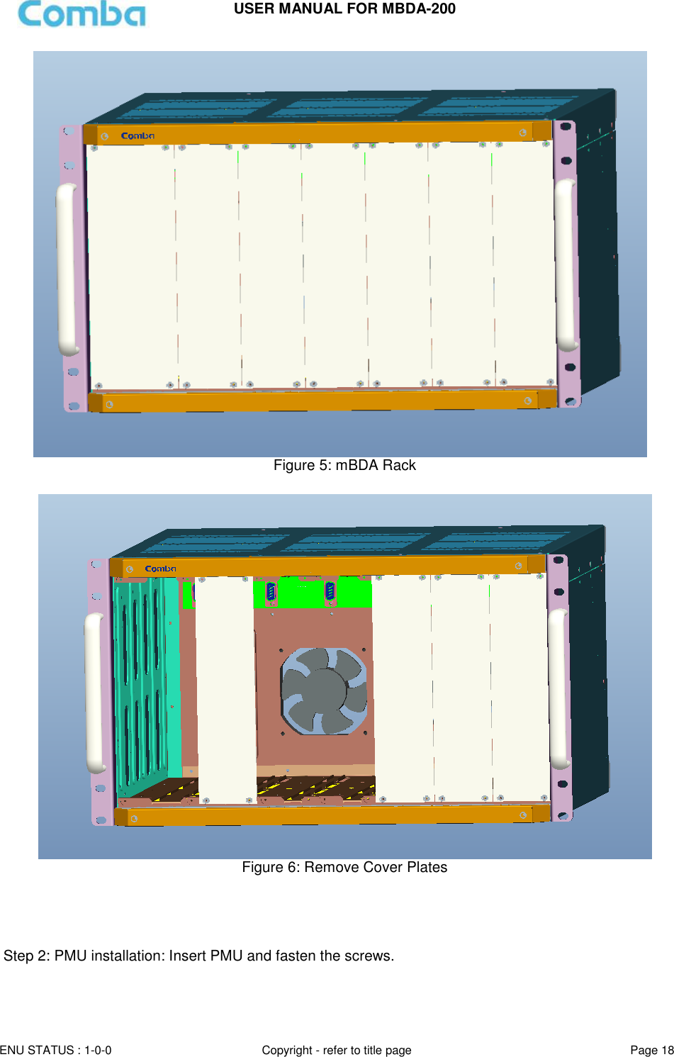
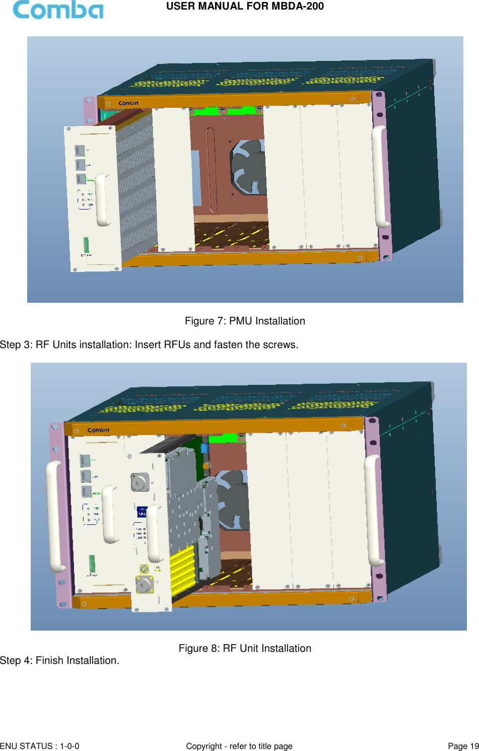
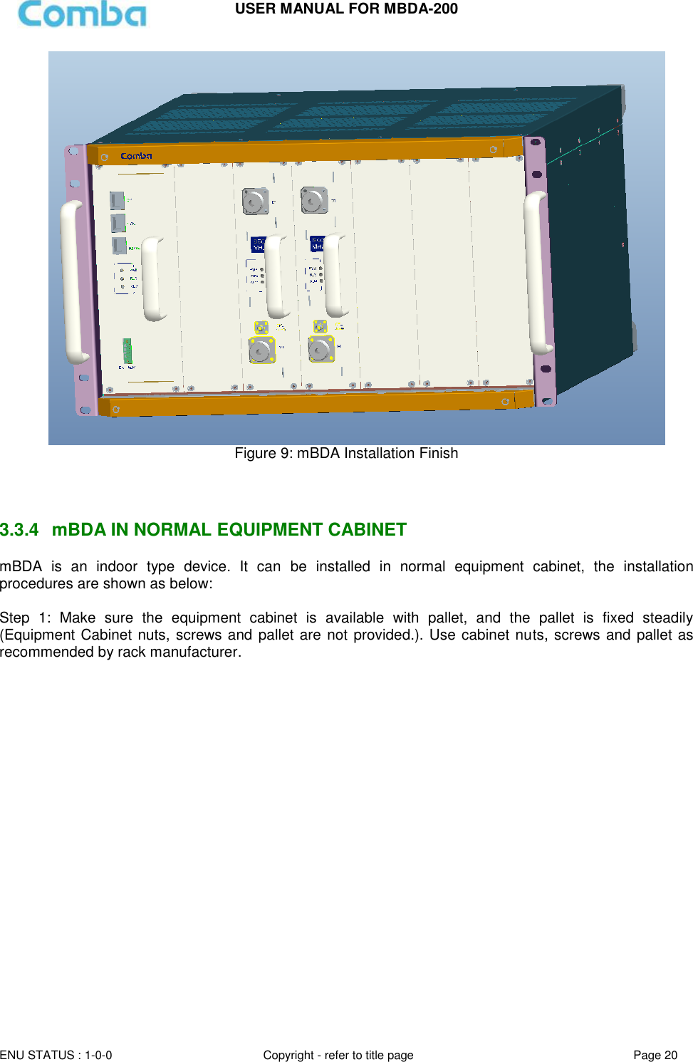
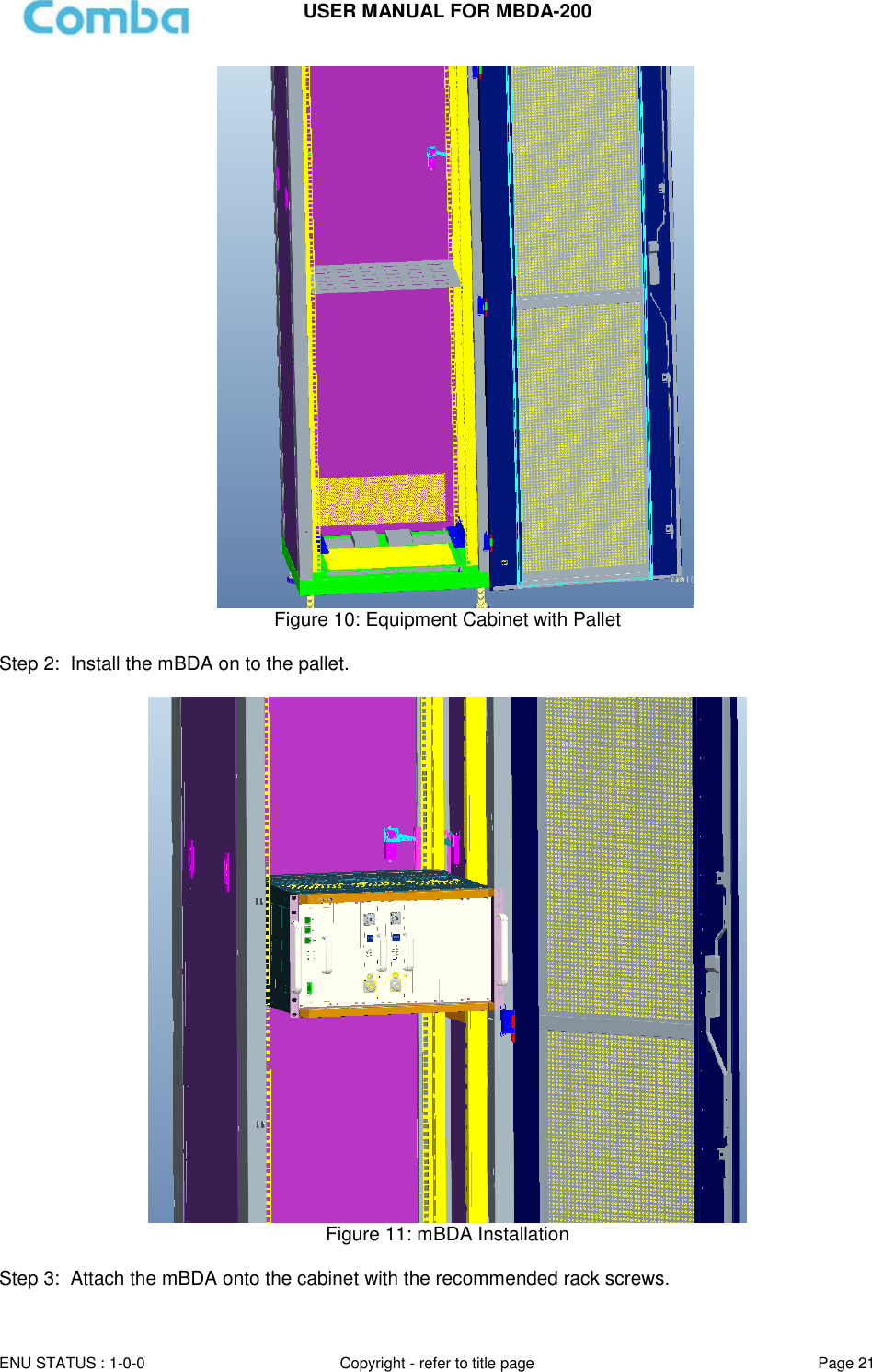
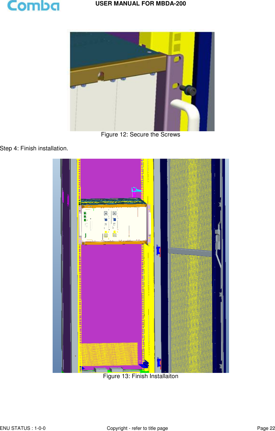
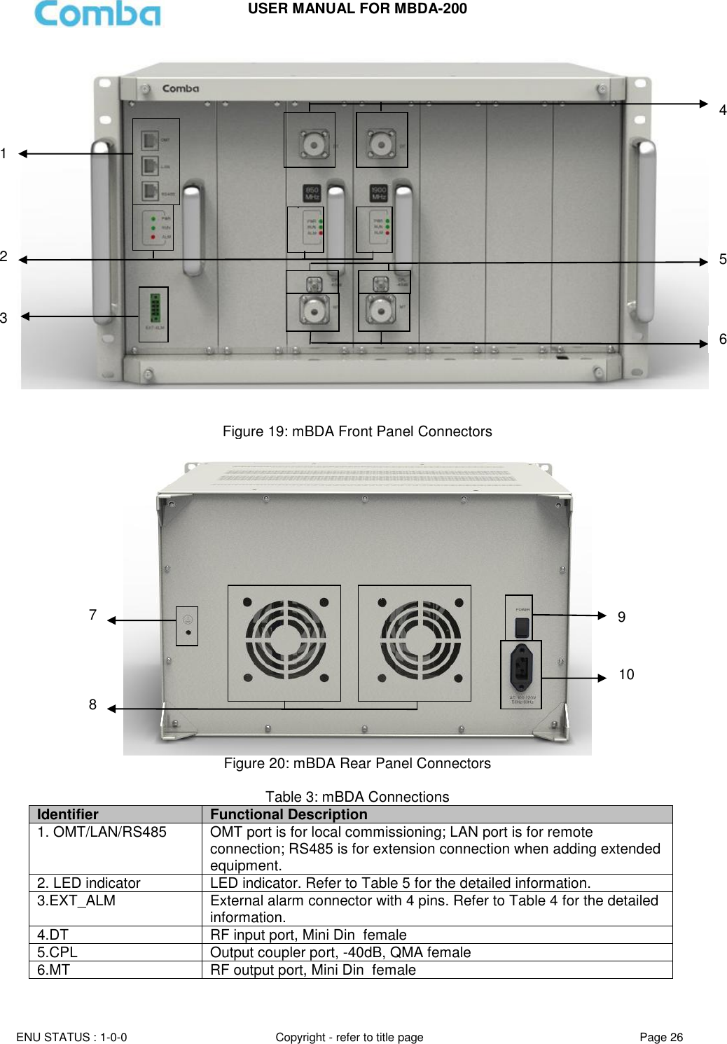
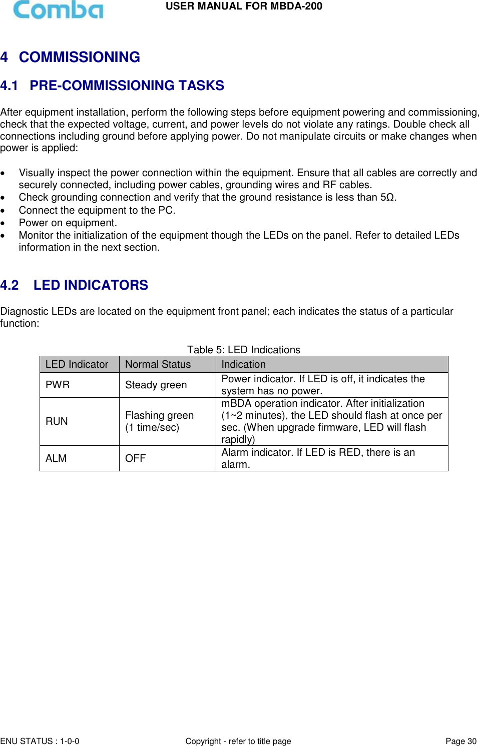
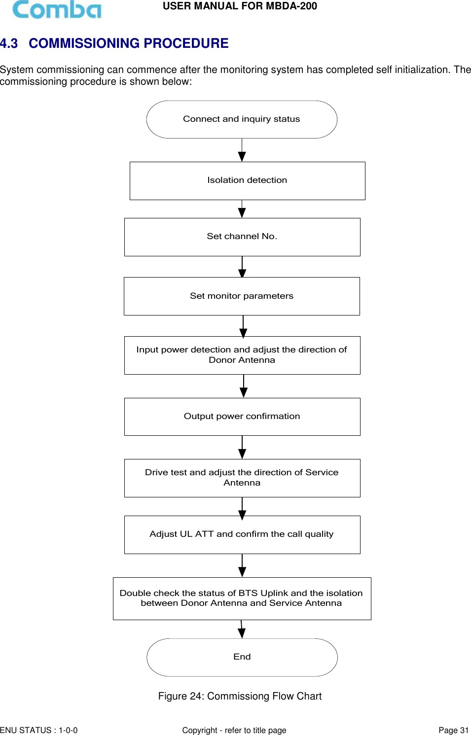
![USER MANUAL FOR MBDA-200 ENU STATUS : 1-0-0 Copyright - refer to title page Page 3 0.1 CONTENTS Section Page 0.1 CONTENTS .................................................................................................................................................... 3 0.2 INDEX TO FIGURES AND TABLES ................................................................................................................... 5 0.3 HISTORY ....................................................................................................................................................... 7 0.4 GLOSSARY OF TERMS .................................................................................................................................... 8 0.5 SAFETY NOTICES AND ADMONISHMENTS ..................................................................................................... 8 1 GENERAL INFORMATION ............................................................................................................................ 10 2 EQUIPMENT DESCRIPTION .......................................................................................................................... 11 2.1 SYSTEM DIAGRAM ...................................................................................................................................... 11 2.2 EQUIPMENT LAYOUT .................................................................................................................................. 12 2.3 EQUIPMENT CONSTITUTION ....................................................................................................................... 13 2.4 KIT OF PART ................................................................................................................................................ 13 3 INSTALLATION ............................................................................................................................................ 14 3.1 WARNINGS AND ALERTS ............................................................................................................................. 14 3.2 SITE PLANNING CONSIDERATIONS .............................................................................................................. 15 3.3 INSTALLATION PROCEDURES ...................................................................................................................... 16 3.4 EQUIPMENT CONNECTORS ......................................................................................................................... 25 3.5 EQUIPMENT CONNECTION ......................................................................................................................... 28 4 COMMISSIONING ....................................................................................................................................... 30 4.1 PRE-COMMISSIONING TASKS ...................................................................................................................... 30 4.2 LED INDICATORS ......................................................................................................................................... 30 4.3 COMMISSIONING PROCEDURE ................................................................................................................... 31 5 WEB GUI ..................................................................................................................................................... 33 5.1 WEB GUI CONNECTION ............................................................................................................................... 33 5.2 WEB GUI INTRODUCTION ........................................................................................................................... 34 5.2.1 [DEVICES] ............................................................................................................................................... 34 5.2.2 [COMMISSIONING] ................................................................................................................................ 37 5.2.3 [FIRMWARE] .......................................................................................................................................... 38 5.2.4 [MANAGEMENT] .................................................................................................................................... 39 5.3 COMMISSIONING PROCEDURE ................................................................................................................... 45 6 MAINTENANCE ........................................................................................................................................... 52](https://usermanual.wiki/Comba-Telecom/MBDA-200/User-Guide-2187614-Page-3.png)
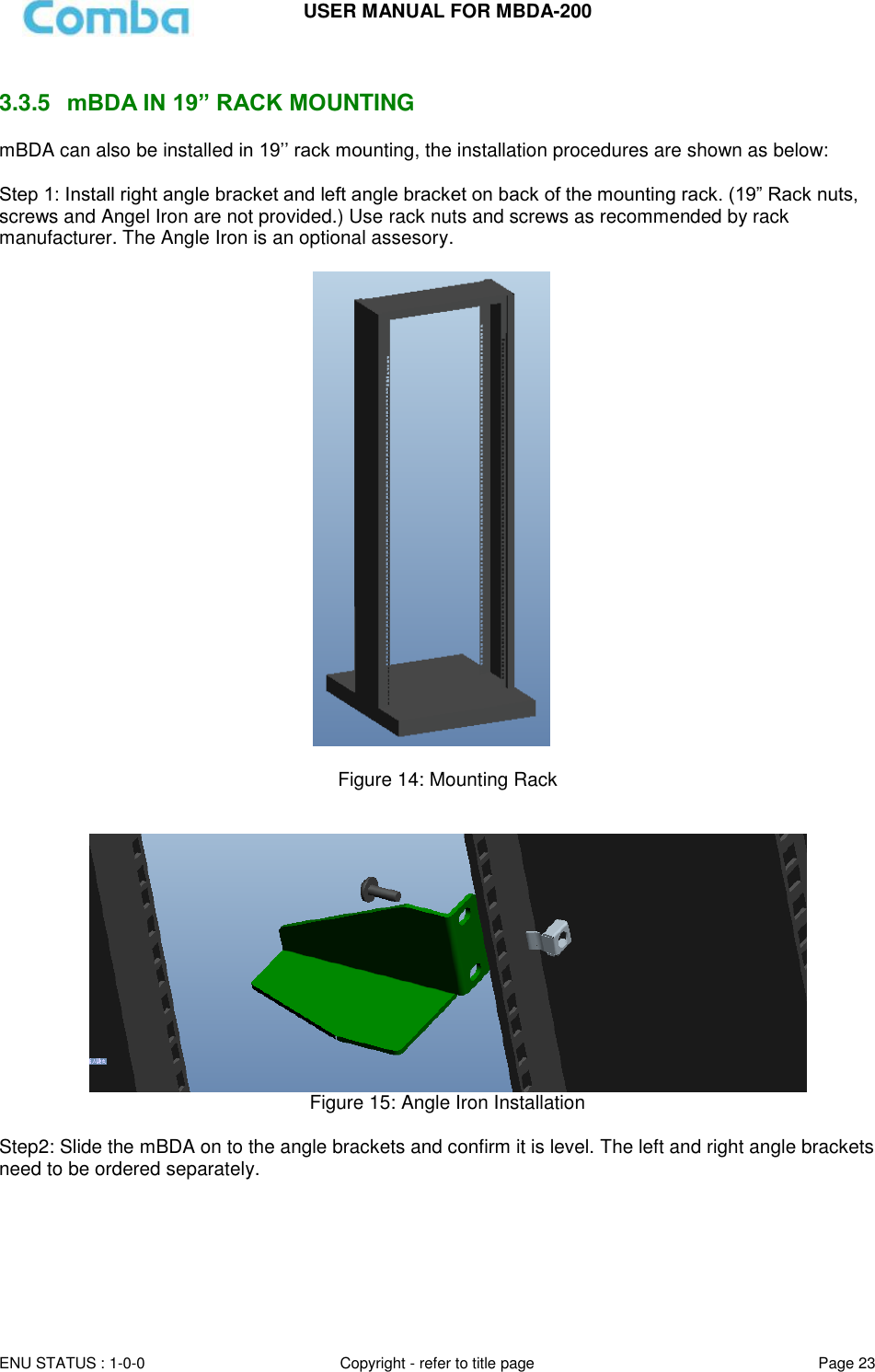
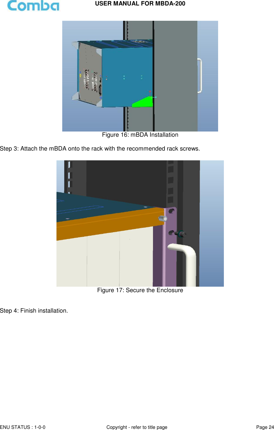
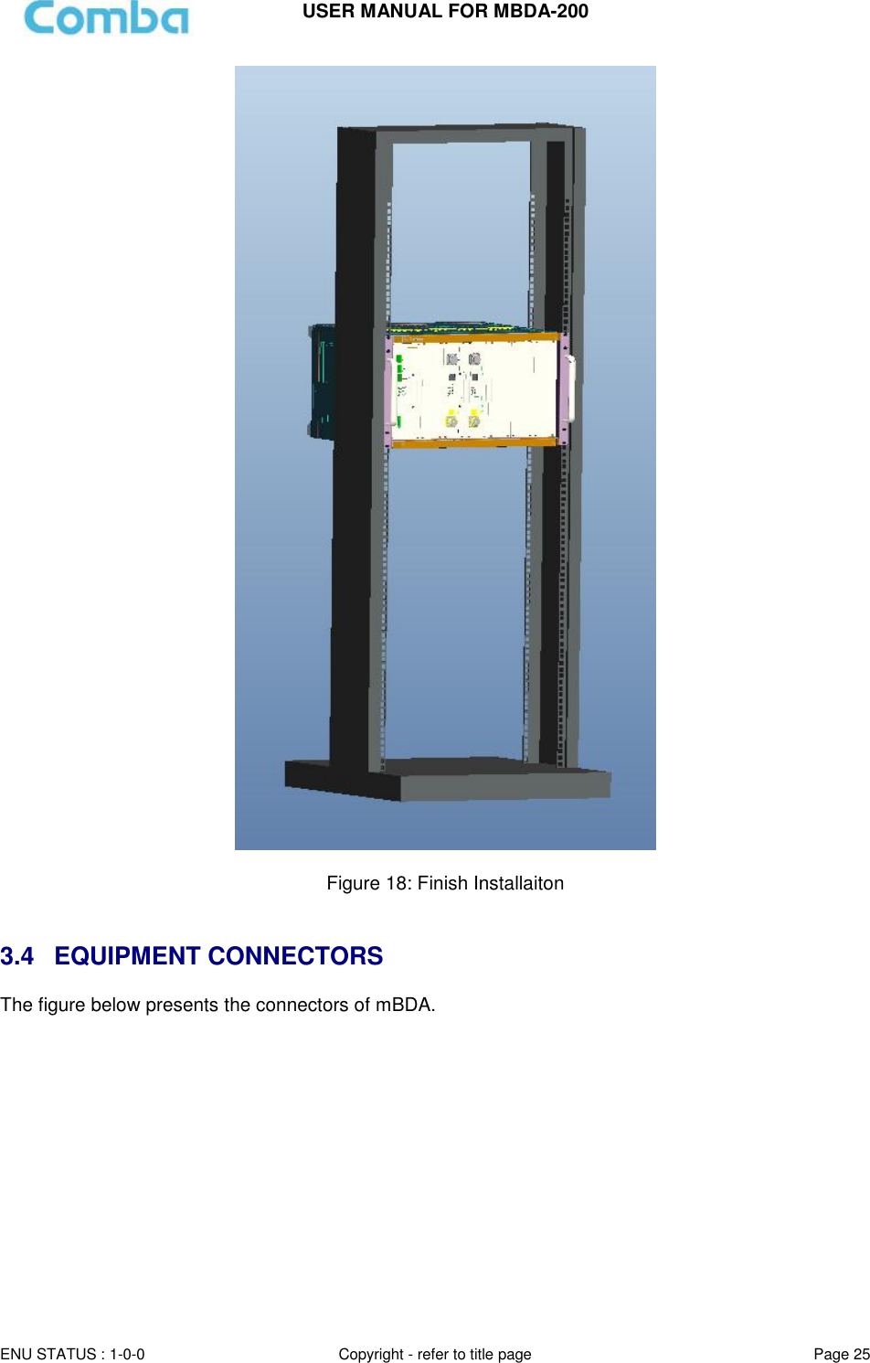
![USER MANUAL FOR MBDA-200 ENU STATUS : 1-0-0 Copyright - refer to title page Page 5 0.2 INDEX TO FIGURES AND TABLES Figure 1: mBDA-200 ................................................................................................................................................. 10 Figure 2: System Diagram ....................................................................................................................................... 11 Figure 3: Layout of mBDA ....................................................................................................................................... 12 Figure 4: mBDA Screen ........................................................................................................................................... 17 Figure 5: mBDA Rack ............................................................................................................................................... 18 Figure 6: Remove Cover Plates .............................................................................................................................. 18 Figure 7: PMU Installation ....................................................................................................................................... 19 Figure 8: RF Unit Installation ................................................................................................................................... 19 Figure 9: mBDA Installation Finish ......................................................................................................................... 20 Figure 10: Equipment Cabinet with Pallet ............................................................................................................. 21 Figure 11: mBDA Installation .................................................................................................................................. 21 Figure 12: Secure the Screws ................................................................................................................................. 22 Figure 13: Finish Installaiton ................................................................................................................................... 22 Figure 14: Mounting Rack........................................................................................................................................ 23 Figure 15: Angle Iron Installation ............................................................................................................................ 23 Figure 16: mBDA Installation .................................................................................................................................. 24 Figure 17: Secure the Enclosure ............................................................................................................................ 24 Figure 18: Finish Installaiton ................................................................................................................................... 25 Figure 19: mBDA Front Panel Connectors ........................................................................................................... 26 Figure 20: mBDA Rear Panel Connectors ............................................................................................................ 26 Figure 21: mBDA Grounding (mBDA Rear Panel) ............................................................................................... 28 Figure 22: mBDA Power Connection (Rear Panel) ............................................................................................. 29 Figure 23: Pins Allocation for “EXT_ALM” Port for mBDA ................................................................................. 29 Figure 24: Commissiong Flow Chart ...................................................................................................................... 31 Figure 25: PC IP Address Setting........................................................................................................................... 33 Figure 26: Input IP Address ..................................................................................................................................... 33 Figure 27: Input Domain Name ............................................................................................................................... 33 Figure 28: Input User Name and Password .......................................................................................................... 34 Figure 29: Web GUI Main Screen .......................................................................................................................... 34 Figure 30: [Devices] Sceen ..................................................................................................................................... 35 Figure 31: Power & Monitoring Unit ....................................................................................................................... 35 Figure 32: RF Unit..................................................................................................................................................... 36 Figure 33: RF Unit Detail Information .................................................................................................................... 37 Figure 34: [Commissioning] Screen ....................................................................................................................... 37 Figure 35: [Firmware] Screen – Upgrade .............................................................................................................. 38 Figure 36: [Firmware] Screen – Pop-up Window 1 .............................................................................................. 38 Figure 37: [Firmware] Screen - Swap .................................................................................................................... 39 Figure 38: [Management] Sceen ............................................................................................................................ 39 Figure 39: Management – Import&Export ............................................................................................................. 40 Figure 40: Management – IP Setting ..................................................................................................................... 41 Figure 41: Management – SNMP Setting.............................................................................................................. 41 Figure 42: Management – Security ........................................................................................................................ 42 Figure 43: Modify Password .................................................................................................................................... 42 Figure 44: Management – Device Reset ............................................................................................................... 43 Figure 45: Management – PA Reset ...................................................................................................................... 43 Figure 46: Management – Device Info ................................................................................................................... 44 Figure 47: Management – Isolation ........................................................................................................................ 44 Figure 48: Management – Report........................................................................................................................... 45 Figure 49: Commissioning Procedure - Start........................................................................................................ 45 Figure 50: Commissioning Procedure – Site Info. Setting .................................................................................. 46 Figure 51: Dev Info & Date/Time ............................................................................................................................ 46 Figure 52: Commissioning Procedure – Isolation Detective ............................................................................... 47 Figure 53: Commissioning Procedure – Isolation Detective Confirm ................................................................ 47](https://usermanual.wiki/Comba-Telecom/MBDA-200/User-Guide-2187614-Page-5.png)
![USER MANUAL FOR MBDA-200 ENU STATUS : 1-0-0 Copyright - refer to title page Page 32 Table 6: Commissioning Procedure Commissioning Tasks Observation 1. On-line and Inquiry status Activate the OMT Main window. The system Initialization will completed in about 2 minutes. Click “Connect” button to enquire the repeater’s status. Proceed if there is no alarm; else check the failure and attend to the alarm. 2. Isolation detection Detect isolation of service antenna and donor antenna. 3. Set Channel No. Keep RF switch ON and set the channel number of the repeater’s operating frequency. 4. Adjust Downlink Output Power and align donor antenna Observe DL input power from measured value. Align the direction of donor antenna until the DL input power reading is maximized. Note: To ensure that the measured DL input power is accurate, one should set the DL ATT to “0” before performing the check. 5. Configure [Equipment ID] Go to [Properties Info] and set [Equipment ID]. 6. Comm. Config Enable the power supply by selecting “On” in [RF] -> [Switch]; go to [Properties Info.] -> [Comm. Config.] and set OMC Phones No. , the service No. of SMSC, Report Mode. 7. Select Monitoring Parameters Select the equipment controlled and monitored parameters. If the external devices are connected to the equipment for management, please enable in the [External Alarm Info.] Interface. 8. Test coverage area field intensity and adjust service antenna. Use test-handset to verify field intensity within the coverage area. If needed, realign the service antenna to achieve the desired coverage. Note: If during operation, the equipment gain could not be set to maximmum or the output power is not high enough due to insufficient donor and service antennas isolation, then the antennas’ position should be changed to increase isolation. If the output power is too high and ALC is activated, then adjust the DL ATT to achieve optimal DL Gain. 9. Verify UL gain and ensure test call produces good voice quality and there is no interfering BTS Adjust UL gain and perform test calls. Typically, the UL gain is set around 5dB less than DL gain. Perform test calls in the coverage area while adjusting UL gain if required. Note: If the repeater is near the BTS and the test call performance is poor, this may be due to UL noise interference to the BTS. Users can calculate and determine if the repeater UL noise will interfere with the BTS. Verify again that there is no unacceptable interference to BTS. End of Section](https://usermanual.wiki/Comba-Telecom/MBDA-200/User-Guide-2187614-Page-32.png)
![5 WEB GUI mBDA can be monitored and controlled by WEB GUI, follow below contents to achieve system parameter setting and commissioning. 5.1 WEB GUI CONNECTION Step 1: Connect PMU OMT port to PC RJ45 port with the supplied Ethernet cable to set up a physical connection. Step 2: Go to laptop Control Panel\Network and Internet\Local Area Connection. Right click it and click Properties. Then follow the steps shown in figure below. Figure 25: PC IP Address Setting Step 3: Open browser (browser IE7.0, IE8.0, Chrome or Firefox, suggest disply resolution is 1024×768), input Web GUI IP address: 192.168.8.101, click [Enter]. NOTE: DHCP and DNS are also available to login Web GUI. The domain name is: www.combaomt.com. Figure 26: Input IP Address Figure 27: Input Domain Name](https://usermanual.wiki/Comba-Telecom/MBDA-200/User-Guide-2187614-Page-33.png)
![USER MANUAL FOR MBDA-200 ENU STATUS : 1-0-0 Copyright - refer to title page Page 34 Step 2: Input User Name: admin; Password (default password: admin). Click [Log in]. Figure 28: Input User Name and Password 5.2 WEB GUI INTRODUCTION After log in, the Web GUI main screen will appear. Figure 29: Web GUI Main Screen On Comba Web GUI Home Screen, there are four Menu bars: [Devices], [Commissioning], [Firmware] and [Management]. 5.2.1 [DEVICES] The [Devices] Screen shows the actual active modules of mBDA.](https://usermanual.wiki/Comba-Telecom/MBDA-200/User-Guide-2187614-Page-34.png)
![USER MANUAL FOR MBDA-200 ENU STATUS : 1-0-0 Copyright - refer to title page Page 35 Figure 30: [Devices] Sceen PMU Main Management Screen Figure 31: Power & Monitoring Unit](https://usermanual.wiki/Comba-Telecom/MBDA-200/User-Guide-2187614-Page-35.png)
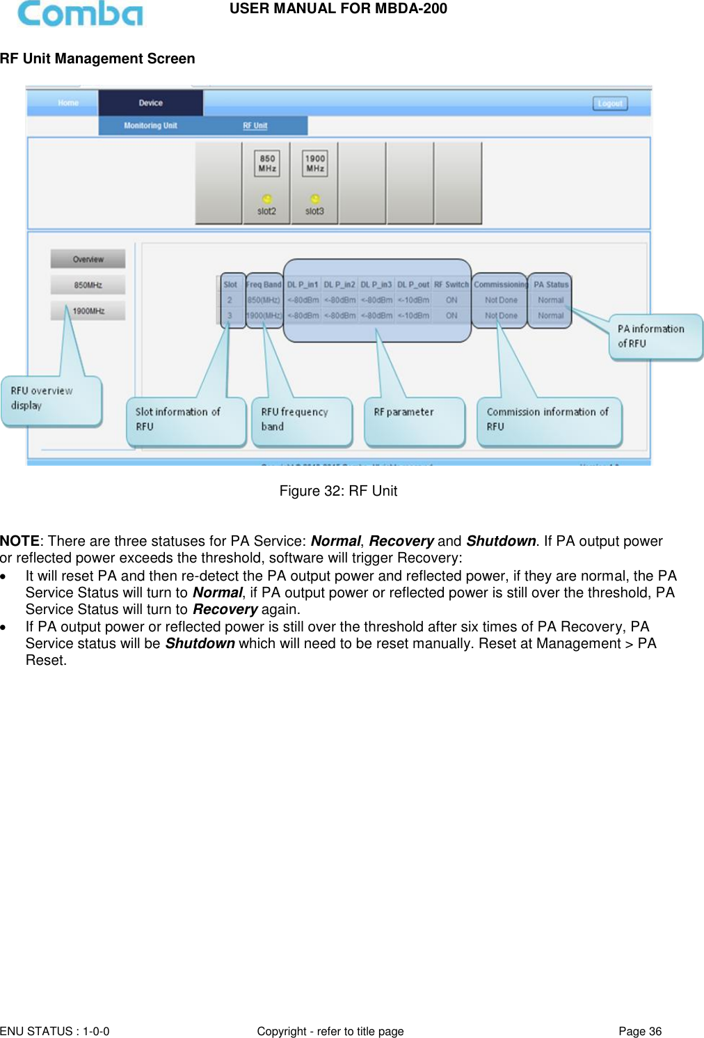
![USER MANUAL FOR MBDA-200 ENU STATUS : 1-0-0 Copyright - refer to title page Page 37 Figure 33: RF Unit Detail Information 5.2.2 [COMMISSIONING] A work flow of the commissioning process is shown on [Commissioning] Screen. Click the [Start] button, the software will guide you through the commissioning step by step. For details, please refer to chapter 5.3. Figure 34: [Commissioning] Screen](https://usermanual.wiki/Comba-Telecom/MBDA-200/User-Guide-2187614-Page-37.png)
![USER MANUAL FOR MBDA-200 ENU STATUS : 1-0-0 Copyright - refer to title page Page 38 5.2.3 [FIRMWARE] There are two functions on the [Firmware] bar: [upgrade] and [swap]. [Upgrade] is used to upgrade software, and [Swap] is to replace current firmware version to the previous one. Follow steps shown in below figure to upgrade firmware. Figure 35: [Firmware] Screen – Upgrade Step 4: After clicking , a window will pop up and click . Figure 36: [Firmware] Screen – Pop-up Window 1 Step 5: Wait for 2~4 minutes while mBDA is being reset. Click to continue. Step 6: Clear browsing history and cookies from browser. NOTE: For PMU software upgrade, users need to re-login Web GUI after reset is done. Follow steps shown in below figure to Swap firmware.](https://usermanual.wiki/Comba-Telecom/MBDA-200/User-Guide-2187614-Page-38.png)
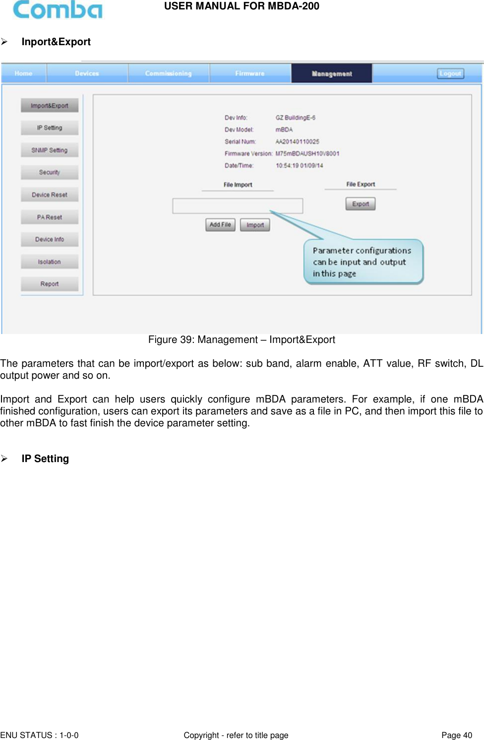
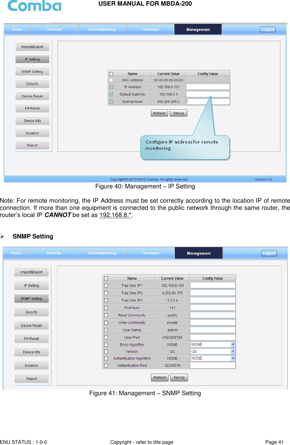
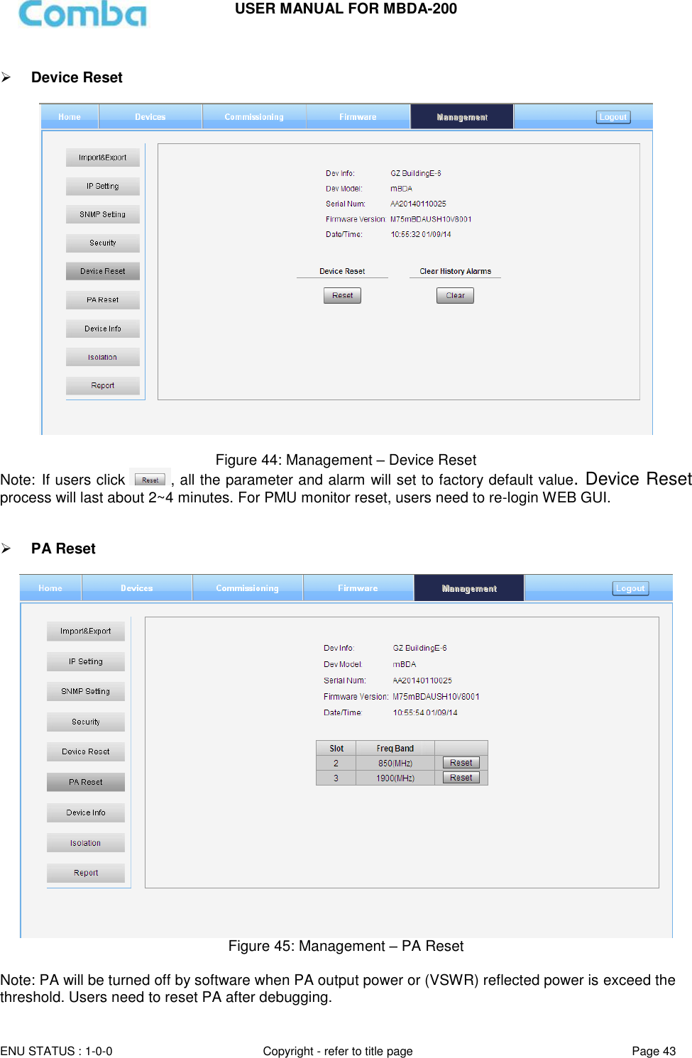
![USER MANUAL FOR MBDA-200 ENU STATUS : 1-0-0 Copyright - refer to title page Page 39 Figure 37: [Firmware] Screen - Swap 5.2.4 [MANAGEMENT] Other parameters can be configured on [Management] Screen. Figure 38: [Management] Sceen There are nine function bars list in the left side of the [Mangement] Screen. Below figures are the introduction of each function bar.](https://usermanual.wiki/Comba-Telecom/MBDA-200/User-Guide-2187614-Page-39.png)
![USER MANUAL FOR MBDA-200 ENU STATUS : 1-0-0 Copyright - refer to title page Page 42 Security Figure 42: Management – Security Click , [Modify Password] window will pop-up. Figure 43: Modify Password Note: Username cannot be modified.](https://usermanual.wiki/Comba-Telecom/MBDA-200/User-Guide-2187614-Page-42.png)
![USER MANUAL FOR MBDA-200 ENU STATUS : 1-0-0 Copyright - refer to title page Page 44 Device Info Figure 46: Management – Device Info Note: Users can input maximum 30 bytes characters in Device Info. Isolation Figure 47: Management – Isolation Note: This Step is the same as step3 of [Commissioning]. Users can check isolation again by clicking Check button.](https://usermanual.wiki/Comba-Telecom/MBDA-200/User-Guide-2187614-Page-44.png)
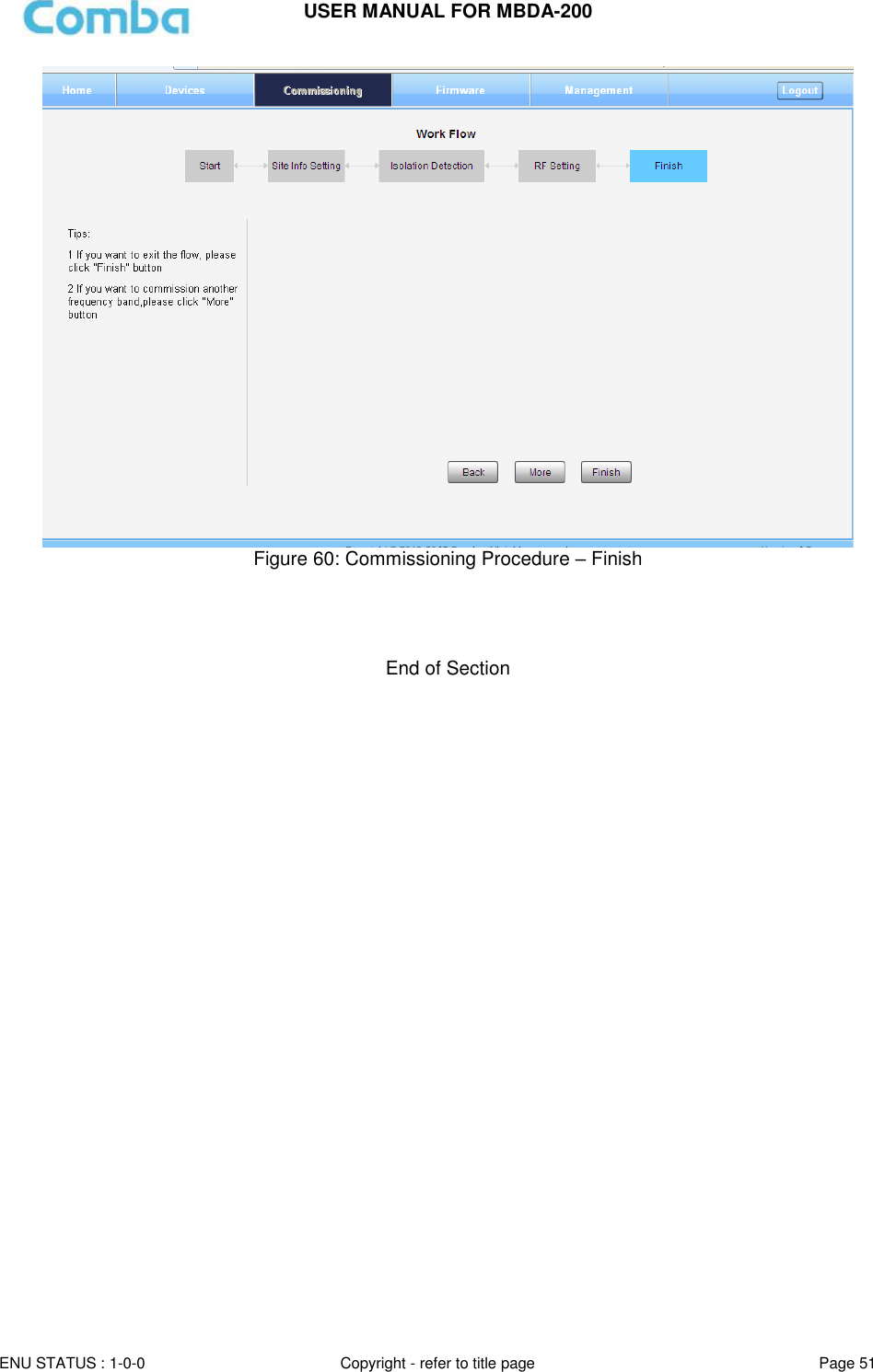
![USER MANUAL FOR MBDA-200 ENU STATUS : 1-0-0 Copyright - refer to title page Page 45 Report Figure 48: Management – Report Note: Click Create to create report (The report cann’t create in IE browser.) and make sure the computer has installed PDF Reader software. If no, users will see nothing. 5.3 COMMISSIONING PROCEDURE To complete the installation and commissioning, users need to follow the steps below. Step 1: Click Menu bar [Commissioning] on home screen, a work flow will show up. Figure 49: Commissioning Procedure - Start](https://usermanual.wiki/Comba-Telecom/MBDA-200/User-Guide-2187614-Page-45.png)
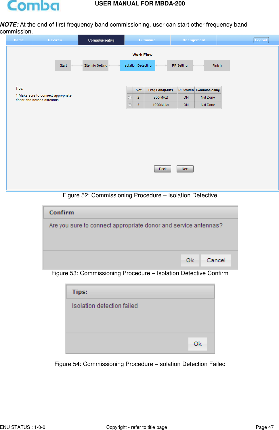
![USER MANUAL FOR MBDA-200 ENU STATUS : 1-0-0 Copyright - refer to title page Page 46 Step 2: Click to start the process. Figure 50: Commissioning Procedure – Site Info. Setting Step 3: Click , users can set the site information. Figure 51: Dev Info & Date/Time Dev Info mainly used to record device location and Date/Time provid a time reference. Click the Config Value of Date/Time, will update Date/time automatically. NOTE: Make sure the device is connected with appropriate donor and service antennas before proceeding to step 4. Step 4: Click to enter to Isolation Detection Screen shown as Figure 52. Select a frequency band (RFU) that need to commission. Click to start Isolation Detecting, then [Confirm] window will pop-up shown as Figure 53. Click to continue. If isolation detection success, the process will go to RF Settiing Screen shown as Figure 55. If failed, a Tips window will pop-up shown as Figure 54, users need to check whether the system isolation is very weak.](https://usermanual.wiki/Comba-Telecom/MBDA-200/User-Guide-2187614-Page-46.png)