Comba Telecom MBDA-200 MBDA BAND SELECTIVE WIRELESS REPEATER User Manual
Comba Telecom Ltd. MBDA BAND SELECTIVE WIRELESS REPEATER
User Manual

B
BA
AN
ND
D
S
SE
EL
LE
EC
CT
TI
IV
VE
E
W
WI
IR
RE
EL
LE
ES
SS
S
R
RE
EP
PE
EA
AT
TE
ER
R
USER MANUAL
MBDA-200 QE: 1-0-0
Comba Telecom Ltd.
mBDA-200

The information contained herein is the responsibility of and is approved by the
following, to whom all enquiries should be directed in the first instance:
This is an unpublished work the copyright in which vests in Comba International
("Comba"). All rights reserved.
The information contained herein is confidential and the property of Comba and
is supplied without liability for errors or omissions. No part may be reproduced,
disclosed or used except as authorised by contract or other written permission.
The copyright and the foregoing restriction on reproduction and use extend to all
media in which the information may be embodied.

USER MANUAL FOR MBDA-200
ENU STATUS : 1-0-0
Copyright - refer to title page
Page 3
0.1 CONTENTS
Section
Page
0.1 CONTENTS .................................................................................................................................................... 3
0.2 INDEX TO FIGURES AND TABLES ................................................................................................................... 5
0.3 HISTORY ....................................................................................................................................................... 7
0.4 GLOSSARY OF TERMS .................................................................................................................................... 8
0.5 SAFETY NOTICES AND ADMONISHMENTS ..................................................................................................... 8
1 GENERAL INFORMATION ............................................................................................................................ 10
2 EQUIPMENT DESCRIPTION .......................................................................................................................... 11
2.1 SYSTEM DIAGRAM ...................................................................................................................................... 11
2.2 EQUIPMENT LAYOUT .................................................................................................................................. 12
2.3 EQUIPMENT CONSTITUTION ....................................................................................................................... 13
2.4 KIT OF PART ................................................................................................................................................ 13
3 INSTALLATION ............................................................................................................................................ 14
3.1 WARNINGS AND ALERTS ............................................................................................................................. 14
3.2 SITE PLANNING CONSIDERATIONS .............................................................................................................. 15
3.3 INSTALLATION PROCEDURES ...................................................................................................................... 16
3.4 EQUIPMENT CONNECTORS ......................................................................................................................... 25
3.5 EQUIPMENT CONNECTION ......................................................................................................................... 28
4 COMMISSIONING ....................................................................................................................................... 30
4.1 PRE-COMMISSIONING TASKS ...................................................................................................................... 30
4.2 LED INDICATORS ......................................................................................................................................... 30
4.3 COMMISSIONING PROCEDURE ................................................................................................................... 31
5 WEB GUI ..................................................................................................................................................... 33
5.1 WEB GUI CONNECTION ............................................................................................................................... 33
5.2 WEB GUI INTRODUCTION ........................................................................................................................... 34
5.2.1 [DEVICES] ............................................................................................................................................... 34
5.2.2 [COMMISSIONING] ................................................................................................................................ 37
5.2.3 [FIRMWARE] .......................................................................................................................................... 38
5.2.4 [MANAGEMENT] .................................................................................................................................... 39
5.3 COMMISSIONING PROCEDURE ................................................................................................................... 45
6 MAINTENANCE ........................................................................................................................................... 52

USER MANUAL FOR MBDA-200
ENU STATUS : 1-0-0
Copyright - refer to title page
Page 4
7 APPENDICES ............................................................................................................................................... 53
7.1 APPENDIX A: TOOLS FOR INSTALLATION AND MAINTENANCE .................................................................... 53
7.2 APPENDIX B: RMA (RETURN MATERIAL AUTHORIZATION) ......................................................................... 54

USER MANUAL FOR MBDA-200
ENU STATUS : 1-0-0
Copyright - refer to title page
Page 5
0.2 INDEX TO FIGURES AND TABLES
Figure 1: mBDA-200 ................................................................................................................................................. 10
Figure 2: System Diagram ....................................................................................................................................... 11
Figure 3: Layout of mBDA ....................................................................................................................................... 12
Figure 4: mBDA Screen ........................................................................................................................................... 17
Figure 5: mBDA Rack ............................................................................................................................................... 18
Figure 6: Remove Cover Plates .............................................................................................................................. 18
Figure 7: PMU Installation ....................................................................................................................................... 19
Figure 8: RF Unit Installation ................................................................................................................................... 19
Figure 9: mBDA Installation Finish ......................................................................................................................... 20
Figure 10: Equipment Cabinet with Pallet ............................................................................................................. 21
Figure 11: mBDA Installation .................................................................................................................................. 21
Figure 12: Secure the Screws ................................................................................................................................. 22
Figure 13: Finish Installaiton ................................................................................................................................... 22
Figure 14: Mounting Rack........................................................................................................................................ 23
Figure 15: Angle Iron Installation ............................................................................................................................ 23
Figure 16: mBDA Installation .................................................................................................................................. 24
Figure 17: Secure the Enclosure ............................................................................................................................ 24
Figure 18: Finish Installaiton ................................................................................................................................... 25
Figure 19: mBDA Front Panel Connectors ........................................................................................................... 26
Figure 20: mBDA Rear Panel Connectors ............................................................................................................ 26
Figure 21: mBDA Grounding (mBDA Rear Panel) ............................................................................................... 28
Figure 22: mBDA Power Connection (Rear Panel) ............................................................................................. 29
Figure 23: Pins Allocation for “EXT_ALM” Port for mBDA ................................................................................. 29
Figure 24: Commissiong Flow Chart ...................................................................................................................... 31
Figure 25: PC IP Address Setting........................................................................................................................... 33
Figure 26: Input IP Address ..................................................................................................................................... 33
Figure 27: Input Domain Name ............................................................................................................................... 33
Figure 28: Input User Name and Password .......................................................................................................... 34
Figure 29: Web GUI Main Screen .......................................................................................................................... 34
Figure 30: [Devices] Sceen ..................................................................................................................................... 35
Figure 31: Power & Monitoring Unit ....................................................................................................................... 35
Figure 32: RF Unit..................................................................................................................................................... 36
Figure 33: RF Unit Detail Information .................................................................................................................... 37
Figure 34: [Commissioning] Screen ....................................................................................................................... 37
Figure 35: [Firmware] Screen – Upgrade .............................................................................................................. 38
Figure 36: [Firmware] Screen – Pop-up Window 1 .............................................................................................. 38
Figure 37: [Firmware] Screen - Swap .................................................................................................................... 39
Figure 38: [Management] Sceen ............................................................................................................................ 39
Figure 39: Management – Import&Export ............................................................................................................. 40
Figure 40: Management – IP Setting ..................................................................................................................... 41
Figure 41: Management – SNMP Setting.............................................................................................................. 41
Figure 42: Management – Security ........................................................................................................................ 42
Figure 43: Modify Password .................................................................................................................................... 42
Figure 44: Management – Device Reset ............................................................................................................... 43
Figure 45: Management – PA Reset ...................................................................................................................... 43
Figure 46: Management – Device Info ................................................................................................................... 44
Figure 47: Management – Isolation ........................................................................................................................ 44
Figure 48: Management – Report........................................................................................................................... 45
Figure 49: Commissioning Procedure - Start........................................................................................................ 45
Figure 50: Commissioning Procedure – Site Info. Setting .................................................................................. 46
Figure 51: Dev Info & Date/Time ............................................................................................................................ 46
Figure 52: Commissioning Procedure – Isolation Detective ............................................................................... 47
Figure 53: Commissioning Procedure – Isolation Detective Confirm ................................................................ 47

USER MANUAL FOR MBDA-200
ENU STATUS : 1-0-0
Copyright - refer to title page
Page 6
Figure 54: Commissioning Procedure –Isolation Detection Failed .................................................................... 47
Figure 55: Commissioning Procedure –Isolation Detection Finish .................................................................... 48
Figure 56: Commissioning Procedure – Subband bandwidth and Switch Setting .......................................... 49
Figure 57: Commissioning Procedure – DL Output Power Setting Screen ..................................................... 49
Figure 58: Commissioning Procedure – DL Output Power Setting ................................................................... 50
Figure 59: DL Output Power Over Exceed ........................................................................................................... 50
Figure 60: Commissioning Procedure – Finish .................................................................................................... 51
Table 1: mBDA Components .................................................................................................................................. 13
Table 2: KOP ............................................................................................................................................................. 13
Table 3: mBDA Connections ................................................................................................................................... 26
Table 4: Pin Definition of “EXT_ALM” Port for mBDA ......................................................................................... 29
Table 5: LED Indications .......................................................................................................................................... 30
Table 6: Commissioning Procedure ....................................................................................................................... 32

USER MANUAL FOR MBDA-200
ENU STATUS : 1-0-0
Copyright - refer to title page
Page 7
0.3 HISTORY
Change No.
ENU
Details Of Change
1
1-0-0
This user manual first created in Jan 2014.

USER MANUAL FOR MBDA-200
ENU STATUS : 1-0-0
Copyright - refer to title page
Page 8
0.4 GLOSSARY OF TERMS
ALC
Automatic Level Control
ATT
Attenuation
BDA
Bi-direction Amplifier
BS
Base Station
BTS
Base Transceiver Station
DL
Downlink
DT
Donor Terminal
FOU
Fiber Optical Unit
GUI
Graphic User Interface
ID
Identification
LNA
Low Noise Amplifier
MCU
Main Control Unit
MT
Mobile Terminal
MTBF
Mean Time Between Failures
MBDA
Master Unit
NC
Normally Closed
NF
Noise Figure
NO
Normally Open
OMC
Operation & Maintenance Center
OMT
Operation & Maintenance Terminal
PA
Power Amplifier
POI
Point of Interconnects
PSU
Power Supply Unit
RF
Radio Frequency
RFU
Radio Frequency Unit
RU
Remote Unit
SMA
Sub-Miniature “A” Connector
TX/RX
Transmit/Receive
UL
Uplink
VAC
Volts Alternating Current
VSWR
Voltage Standing Wave Ratio
WCDMA
Wideband Code Division MBDAltiple Access
0.5 SAFETY NOTICES AND ADMONISHMENTS
This document contains safety notices in accordance with appropriate standards. In the interests of
conformity with the territory standards for the country concerned, the equivalent territorial admonishments
are also shown.

USER MANUAL FOR MBDA-200
ENU STATUS : 1-0-0
Copyright - refer to title page
Page 9
Any installation, adjustment, maintenance and repair of the equipment must only be carried out by trained,
authorized personnel. At all times, personnel must comply with any safety notices and instructions.
Specific hazards are indicated by symbol labels on or near the affected parts of the equipment. The labels
conform to international standards, are triangular in shape, and are coloured black on a yellow
background. An informative text label may accompany the symbol label.
Hazard labeling is supplemented by safety notices in the appropriate equipment manual. These notices
contain additional information on the nature of the hazard and may also specify precautions.
WARNING! This is NOT a CONSUMER device. It is designed for installation by FCC LICENSEES and
QUALIFIED INSTALLERS. You MUST have and FCC LICENSE or express consent of an FCC License
to operate this device. Unauthorized use may result in signification forfeiture penalties, including penalties
in excess of $100,000 for each continuing violation.
Note: The grantee is not responsible for any changes or modifications not expressly approved by the
party responsible for compliance. Such modifications could void the user’s authority to operate the
equipment.
This device complies with Part 15 of the FCC Rules. Operation is subject to the following two conditions:
(1) this device may not cause harmful interference, and (2) this device must accept any interference
received, including interference that may cause undesired operation.
For compliance with the general population RF exposure limits, each individual antenna used for this
transmitter must be installed to provide a separation distance greater than 41.4986cm or more from all
persons during normal operation and must not be co-located with any other antenna for meeting RF
exposure requirements.
Alert:
These draw the attention of personnel to hazards that may cause damage to the equipment. An example
of use is the case of static electricity hazard.
Caution notices may also be used in the handbook to draw attention to matters that do not constitute a
risk of causing damage to the equipment but where there is a possibility of seriously impairing its
performance, e.g. by mishandling or gross maladjustment. Warnings and Cautions within the main text do
not incorporate labels and may be in shortened form.
The application antenna and RF cable are not provided. The antenna gain should not exceed 10 dBi.
End of Section
USER MANUAL FOR MBDA-200
ENU STATUS : 1-0-0
Copyright - refer to title page
Page 10
1 GENERAL INFORMATION
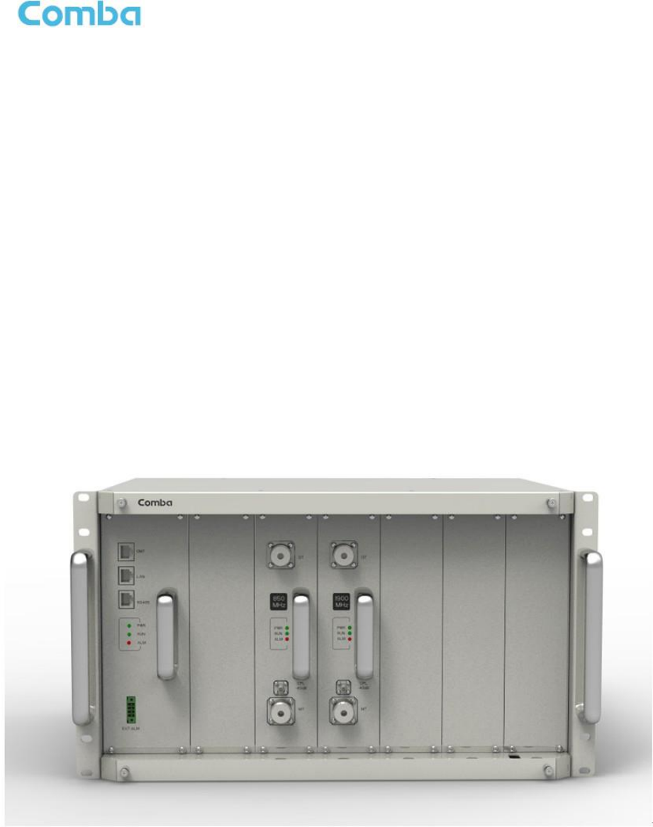
The mBDA-200 Band Selective Wireless Repeater is designed for operation in 850MHz and 1900MHz
networks.Digital band-specific linear amplifier amplifies the desired BTS carriers and provides superior
out-of-band rejection. Typical units with adjustable bandwidth are programmed to specific requirements of
the network. Remote configuration and surveillance is possible through Comba’s remote control and
monitoring system, via PC or wireless modem to the OMC.
Main feature:
mBDA-200 is a high quality repeater with the following features:
Supports GSM, CDMA and WCDMA operating.
Supports multi operator configurations and up to 3 sub bands per band.
Adjustable sub band via OMT software.
Friendly and easy Web OMT interface via RJ45 connection.
Integrated network card for remote configuration, monitoring and control.
The figure below shows the enclosure.
Figure 1: mBDA-200
NOTE: RF module is slot undependent.
End of Section
USER MANUAL FOR MBDA-200
ENU STATUS : 1-0-0
Copyright - refer to title page
Page 11
2 EQUIPMENT DESCRIPTION
2.1 SYSTEM DIAGRAM
Donor
Ant
Modem
Power
Supply
Alarm
Indicator
DL PA
UL PA UL LNA
DL LNA
Main Control Unit
DT
MT
Mobile
Mobile
Ant
Digital Frequency
Selective Module
DL PA
UL PA UL LNA
DL LNA
Digital Frequency
Selective Module
DT
MT
Ant
Mobile
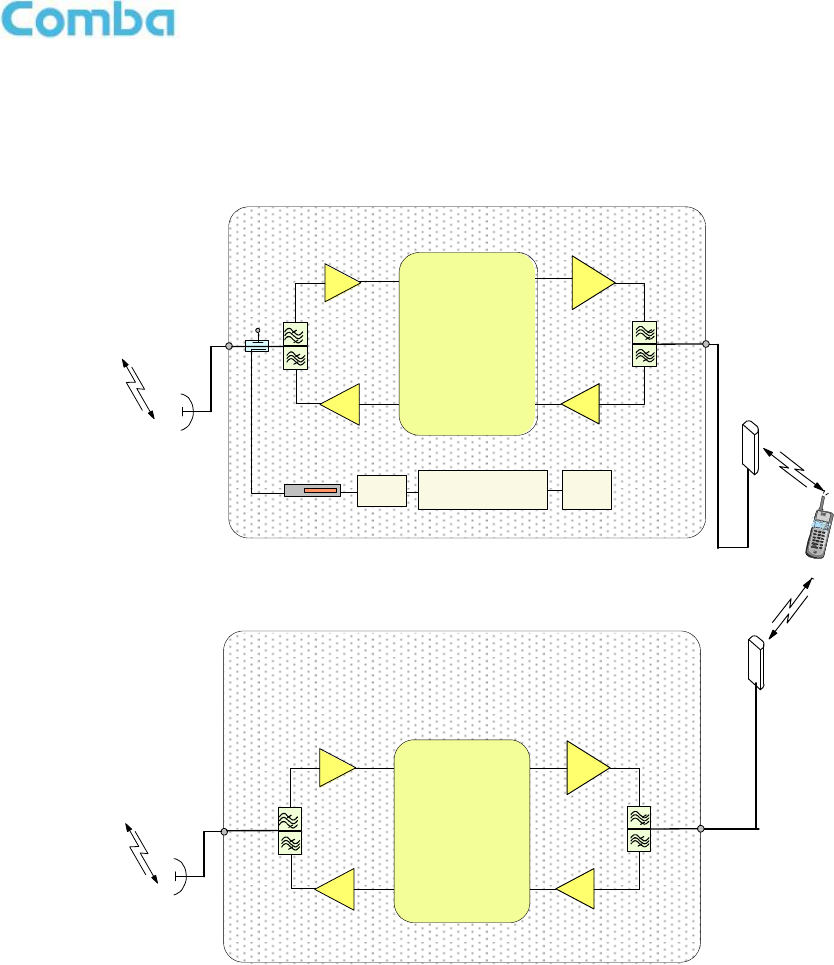
Figure 2: System Diagram
In the downlink, the BTS signals are received by donor antenna of the repeater. After the duplexer, the
signals are sent to the LNA module for pre-amplification and digital RF integrated module for digital
filtering and frequency conversion. Then the DL signals will be sent to downlink PA to amplify power and
filter via duplexer. After amplification, the signals are transmitted via the MT port to the service antenna.
In the uplink, the mobile signals are received by the service antenna. After the MT port integrated
duplexer, the signals are sent to the LNA, integrated module for digital filtering, then to PA for power
amplification and to duplexer. After that, the uplink signals are sent to the donor antenna for transmission
back to the BTS.
USER MANUAL FOR MBDA-200
ENU STATUS : 1-0-0
Copyright - refer to title page
Page 12
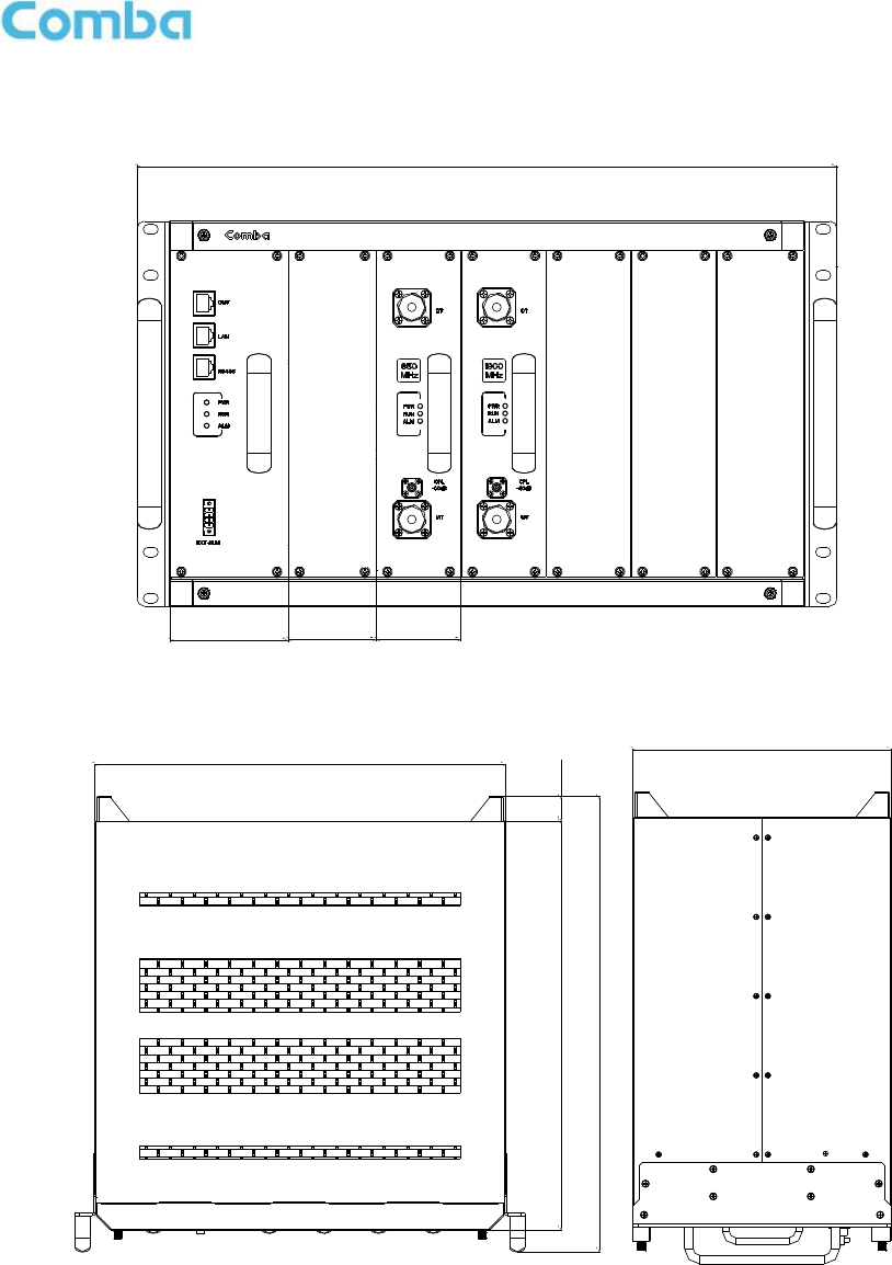
2.2 EQUIPMENT LAYOUT
58.6
482
81.4 58.6
26.1436
485.6
439
265.2
Figure 3: Layout of mBDA
USER MANUAL FOR MBDA-200
ENU STATUS : 1-0-0
Copyright - refer to title page
Page 13
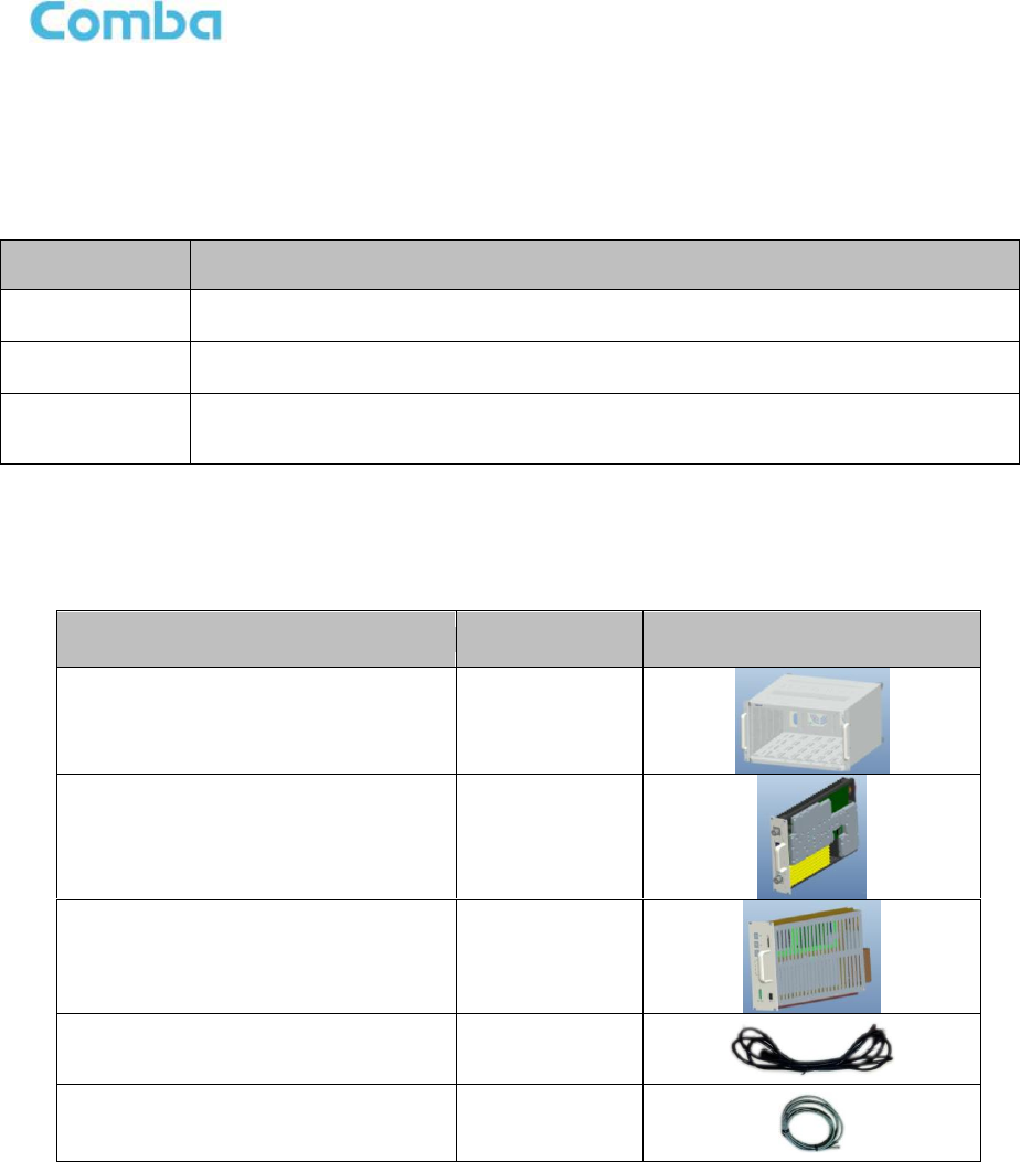
2.3 EQUIPMENT CONSTITUTION
mBDA consists of the following parts:
Table 1: mBDA Components
Module
Description
mBDA-RACK
There are total 7 slots in the main chassis, where six slots for RF Units and
Combiner Units, rest-one slot for Power & Monitoring Unit.
mBDA-PMU
Power & Monitoring Unit (PMU) converts the input voltage into stable DC to supply
power for each RF module and provides monitor control.
mBDA-RFU
RF Unit processes UL/DL signal and amplifies the signal for coverage.
2.4 KIT OF PART
Table 2: KOP
Item
Qty
Image
Rack
1
RF Unit (RFU)
(Packing separately)
1~2
Power & Monitoring Unit (PMU)
(Packing separately)
1
Power Supply Cable
(13 Feet 1 inch)
1
Communication Cable
1
End of Section

USER MANUAL FOR MBDA-200
ENU STATUS : 1-0-0
Copyright - refer to title page
Page 14
3 INSTALLATION
3.1 WARNINGS AND ALERTS
Radio Frequency Energies
There may be situations, particularly for workplace environments near high-powered RF sources, where
recommended limits for safe exposure of human beings to RF energy could be exceeded. In such cases,
restrictive measures or actions may be necessary to ensure the safe use of RF energy.
High Voltage
The equipment has been designed and constructed to prevent practicable danger, as far as reasonably
possible. Any work activity on or near equipment involving installation, operation or maintenance must be
free from danger, as far as reasonably possible.
Where there is a risk of damage to electrical systems involving adverse weather, extreme temperatures,
wet, corrosive or dirty conditions, flammable or explosive atmospheres, the system must be suitably
installed to prevent danger.
Protective Earthing
For the purpose of protecting individuals fromelectrical risk, the equipment provided must be safety in
design and properly maintained and used.
Handling Precautions
This covers a range of activities including lifting, lowering, pushing, pulling, carrying, moving, holding or
restraining an object or person. It also covers activities that require the use of force or effort, such as
pulling a lever, or operating power tools.
Electrostatic Discharge (ESD)
Observe standard precautions for handling ESD-sensitive devices. Assume that all solid-state electronic
devices are ESD-sensitive. Ensure the use of a grounded wrist strap or equivalent while working with
ESD-sensitive devices. Transport, store, and handle ESD-sensitive devices in static-safe environments.

USER MANUAL FOR MBDA-200
ENU STATUS : 1-0-0
Copyright - refer to title page
Page 15
3.2 SITE PLANNING CONSIDERATIONS
3.2.1 SITE PLANNING
Site Considerations
There may be situations, particularly for workplace environments near high-powered RF sources, where
recommended limits for safe exposure of human beings to RF energy could be exceeded. In such cases,
restrictive measures or actions may be necessary to ensure the safe use of RF energy.
Installation Location
Mounting surface shall be capable of supporting the weight of the equipment.
In order to avoid electromagnetic interference, a proper mounting location must be selected to minimize
interference from electromagnetic sources such as large electrical equipment.
Environmental
Humidity has an adverse effect on the reliability of the equipment. It is recommended to install the
equipment in locations having stable temperature and unrestricted air-flow.
The installation location for the system should be well ventilated. The equipment has been designed to
operate at the temperature range and humidity level as stated in the product specifications.
Powering
The power & monitoring unit (PMU) provides power to all modules within the equipment. Depending on
the product variant, it is recommended that the PMU operates on a dedicated AC circuit breaker or fused
circuit.
Grounding Requirement
Verify that the equipment has been well grounded. This includes antennas and all cables connected to
the system. Ensure lightning protection for the antennas is properly grounded.
Cable Routing
Depending on equipment configuration, a variety of types of cables are connected to the equipment:
coaxial cables, power cable, communication cable, and commissioning cable. Where applicable, ensure
cables are properly routed and secured so that they are not damaged.
Manual Handling
During transportation and installation, take necessary handling precautions to avoid potential physical
injury to the installation personnel and the equipment.

USER MANUAL FOR MBDA-200
ENU STATUS : 1-0-0
Copyright - refer to title page
Page 16
3.2.2 SYSTEM INSTALLATION CHECKLIST
Working space available for installation and maintenance for each mounting arrangement. Ensure
unrestricted airflow.
Ensure earthing point is within reach of the ground wire. (2m; 6 ft. 10 in.).
Ensure a power source is within reach of the power cord and the power source has sufficient
capacity.
Where appropriate, ensure unused RF connectors are terminated.
Where appropriate, ensure unused optical fiber connectors are protected.
Do not locate the equipment near large transformers or motors that may cause electromagnetic
interference.
Reduce signal loss in feeder cable by minimizing the length and number of RF connections.
Ensure the equipment will be operated within the stated environment (refer to datasheet).
Where appropriate, confirm available of suitably terminated grade of RF.
Observe handling of all cables to prevent damage.
3.3 INSTALLATION PROCEDURES
3.3.1 GOODS INWARDS INSPECTION
mBDA was factory tested, inspected, packed, and delivered to the carrier with utmost care. Do not accept
shipment from carrier which shows damage or shortage until the carrier’s agent endorses a statement of
the irregularity on the face of the carrier’s receipt. Without documentary evidence, a claim cannot be
processed.
Open and check each package against the packing list. For any shortage, contact Comba Telecom
Systems. Do not remove items from packing materials until installation.
3.3.2 TOOLS
See Appendix A for a full list of tools required for installation and maintenance.
USER MANUAL FOR MBDA-200
ENU STATUS : 1-0-0
Copyright - refer to title page
Page 17
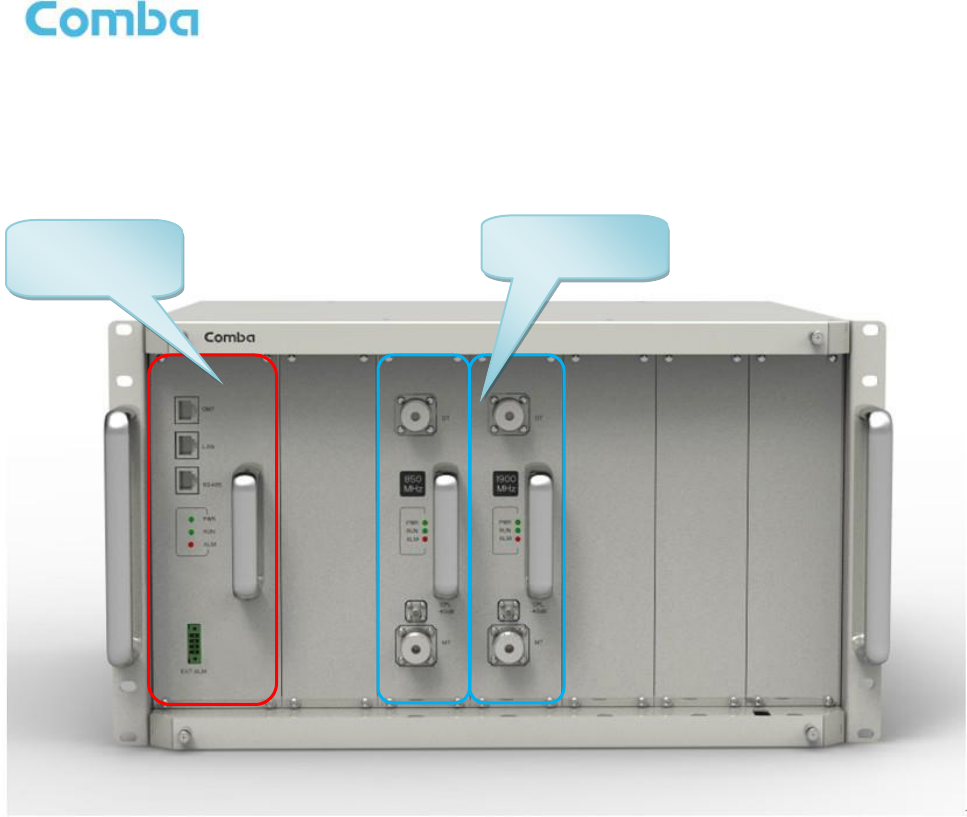
3.3.3 ASSEMBLING
mBDA consists of 3 parts: Rack, PMU and RFUs. All the units are packed separately. Follow the steps
below to assemble.
Figure 4: mBDA Screen
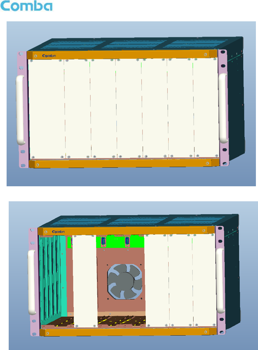
Step1: The rack with cover plates is shown as Figure 5. Please remove the cover plates, before installing
related modules. Show as Figure 6. PMU must be installed at the left slot; RF Units are slot undependent,
and can be installed to other six slots.
Power &
Monitoring Unit
RF Unit
USER MANUAL FOR MBDA-200
ENU STATUS : 1-0-0
Copyright - refer to title page
Page 18
Figure 5: mBDA Rack
Figure 6: Remove Cover Plates
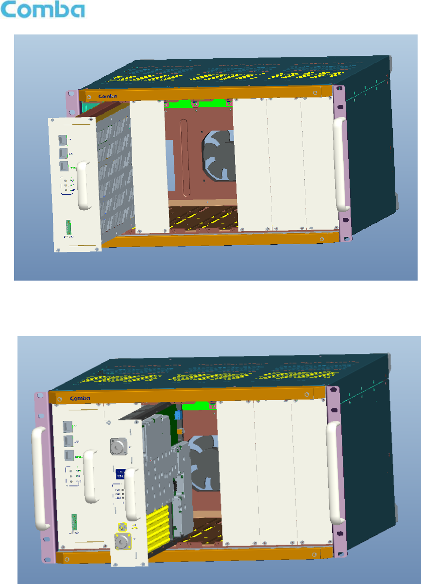
Step 2: PMU installation: Insert PMU and fasten the screws.
USER MANUAL FOR MBDA-200
ENU STATUS : 1-0-0
Copyright - refer to title page
Page 19
Figure 7: PMU Installation
Step 3: RF Units installation: Insert RFUs and fasten the screws.
Figure 8: RF Unit Installation
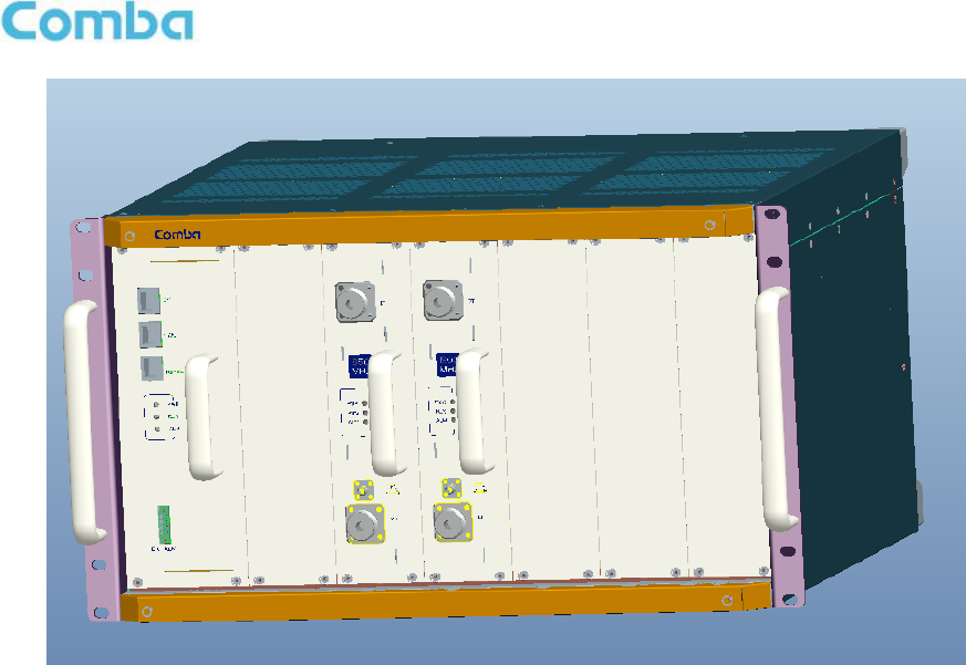
Step 4: Finish Installation.
USER MANUAL FOR MBDA-200
ENU STATUS : 1-0-0
Copyright - refer to title page
Page 20
Figure 9: mBDA Installation Finish
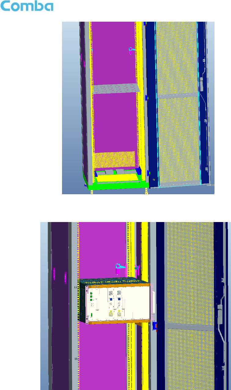
3.3.4 mBDA IN NORMAL EQUIPMENT CABINET
mBDA is an indoor type device. It can be installed in normal equipment cabinet, the installation
procedures are shown as below:
Step 1: Make sure the equipment cabinet is available with pallet, and the pallet is fixed steadily
(Equipment Cabinet nuts, screws and pallet are not provided.). Use cabinet nuts, screws and pallet as
recommended by rack manufacturer.
USER MANUAL FOR MBDA-200
ENU STATUS : 1-0-0
Copyright - refer to title page
Page 21
Figure 10: Equipment Cabinet with Pallet
Step 2: Install the mBDA on to the pallet.
Figure 11: mBDA Installation
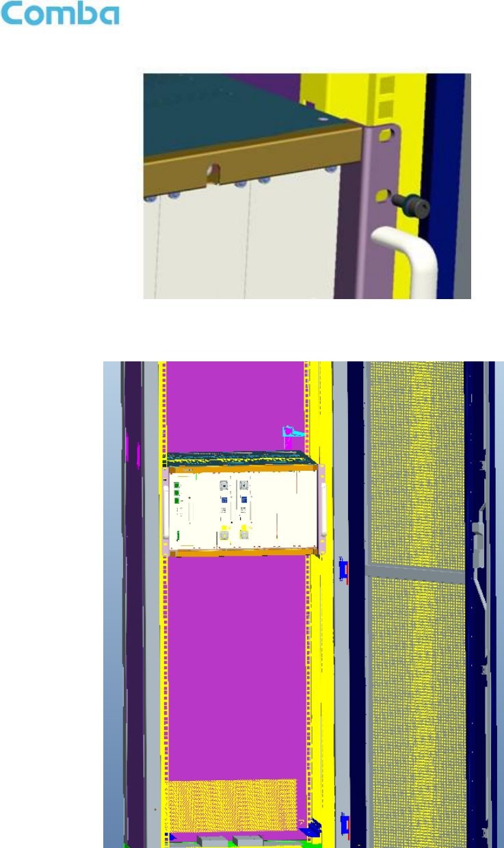
Step 3: Attach the mBDA onto the cabinet with the recommended rack screws.
USER MANUAL FOR MBDA-200
ENU STATUS : 1-0-0
Copyright - refer to title page
Page 22
Figure 12: Secure the Screws
Step 4: Finish installation.
Figure 13: Finish Installaiton
USER MANUAL FOR MBDA-200
ENU STATUS : 1-0-0
Copyright - refer to title page
Page 23
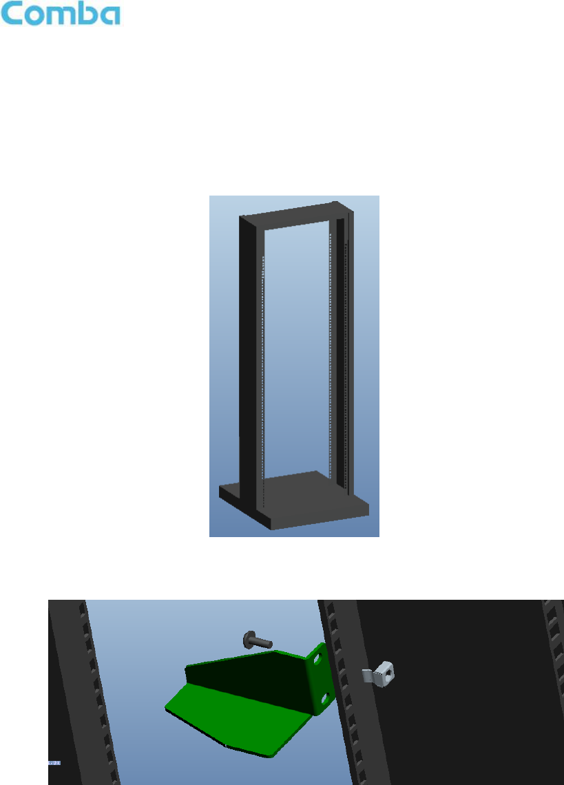
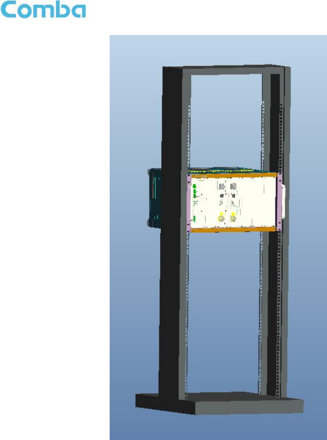
3.3.5 mBDA IN 19” RACK MOUNTING
mBDA can also be installed in 19’’ rack mounting, the installation procedures are shown as below:
Step 1: Install right angle bracket and left angle bracket on back of the mounting rack. (19” Rack nuts,
screws and Angel Iron are not provided.) Use rack nuts and screws as recommended by rack
manufacturer. The Angle Iron is an optional assesory.
Figure 14: Mounting Rack
Figure 15: Angle Iron Installation
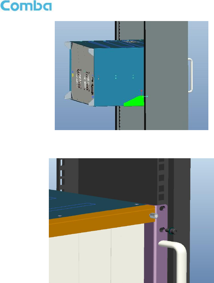
Step2: Slide the mBDA on to the angle brackets and confirm it is level. The left and right angle brackets
need to be ordered separately.
USER MANUAL FOR MBDA-200
ENU STATUS : 1-0-0
Copyright - refer to title page
Page 24
Figure 16: mBDA Installation
Step 3: Attach the mBDA onto the rack with the recommended rack screws.
Figure 17: Secure the Enclosure
Step 4: Finish installation.
USER MANUAL FOR MBDA-200
ENU STATUS : 1-0-0
Copyright - refer to title page
Page 25
Figure 18: Finish Installaiton
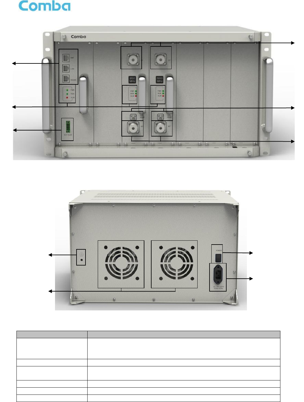
3.4 EQUIPMENT CONNECTORS
The figure below presents the connectors of mBDA.
USER MANUAL FOR MBDA-200
ENU STATUS : 1-0-0
Copyright - refer to title page
Page 26
Figure 19: mBDA Front Panel Connectors
Figure 20: mBDA Rear Panel Connectors
Table 3: mBDA Connections
Identifier
Functional Description
1. OMT/LAN/RS485
OMT port is for local commissioning; LAN port is for remote
connection; RS485 is for extension connection when adding extended
equipment.
2. LED indicator
LED indicator. Refer to Table 5 for the detailed information.
3.EXT_ALM
External alarm connector with 4 pins. Refer to Table 4 for the detailed
information.
4.DT
RF input port, Mini Din female
5.CPL
Output coupler port, -40dB, QMA female
6.MT
RF output port, Mini Din female
1
2
3
4
5
6
7
8
9
10

USER MANUAL FOR MBDA-200
ENU STATUS : 1-0-0
Copyright - refer to title page
Page 27
7.
Grounding connector.
8. FAN
Fan inside
9. POWER
Power switch.
10. AC100~240V
AC power supply connector.
USER MANUAL FOR MBDA-200
ENU STATUS : 1-0-0
Copyright - refer to title page
Page 28
3.5 EQUIPMENT CONNECTION
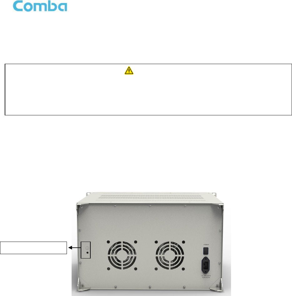
3.5.1 GROUNDING CONNECTION
3.5.2 mBDA GROUNDING CONNECTION
Step 1: Connect the GND cable to the GND connector and the building EARTH. Recommended GND
cable size is # 12 AWG.
Step 2: Ensure the GND cable is connected to building GND.
Figure 21: mBDA Grounding (mBDA Rear Panel)
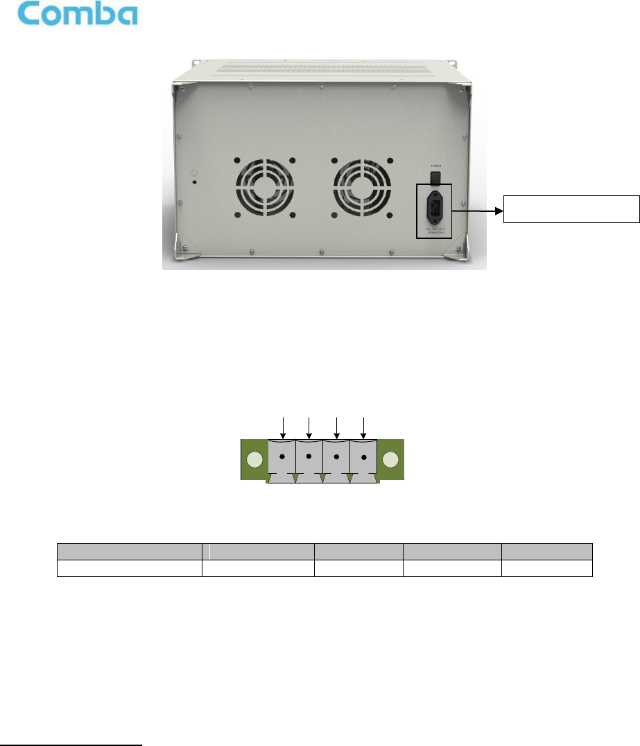
3.5.3 mBDA CONNECTIONS
Step1: Connect the mBDA DT port to the RF Source downlink, and then connect mBDA MT port with RF
Source uplink.
Step 2: Connect the power cable to the power supply port (100-240VAC, 1Amp maximmum).
WARNING!
This unit must always be grounded. Consult an appropriate electrical
inspection authority or an electrician if you are uncertain that suitable
grounding is available.
Do not connect power before grounding.
Grouding Connector
USER MANUAL FOR MBDA-200
ENU STATUS : 1-0-0
Copyright - refer to title page
Page 29
Figure 22: mBDA Power Connection (Rear Panel)
3.5.4 EXTERNAL ALARM CONNECTION
For EXT-ALM, this is a 4-pin connector. The following figure and table show the pin allocation and
definition. Pin numbering are shown looking-into the connector on the enclosure.
123
4
Figure 23: Pins Allocation for “EXT_ALM” Port for mBDA
Table 4: Pin Definition of “EXT_ALM” Port for mBDA
Pin number
1
2
3
4
Alarm definition
EXT. Alarm 1
GND
EXT. Alarm 2
GND
Note: Users need to configure Ext Alm 1~2 on WEB GUI to realize External Alarm (Refer to Chapter 5).
3.5.5 CONNECT TO PC
The local commissioning and management for mBDA is achieved through connecting to the WEB based
GUI.
Connect mBDA to PC
Connect mBDA “OMT” port (RJ45) to the RJ45 port of PC with supplied Ethernet cable to achieve local
monitoring and management.
End of Section
Power Connector

USER MANUAL FOR MBDA-200
ENU STATUS : 1-0-0
Copyright - refer to title page
Page 30
4 COMMISSIONING
4.1 PRE-COMMISSIONING TASKS
After equipment installation, perform the following steps before equipment powering and commissioning,
check that the expected voltage, current, and power levels do not violate any ratings. Double check all
connections including ground before applying power. Do not manipulate circuits or make changes when
power is applied:
Visually inspect the power connection within the equipment. Ensure that all cables are correctly and
securely connected, including power cables, grounding wires and RF cables.
Check grounding connection and verify that the ground resistance is less than 5Ω.
Connect the equipment to the PC.
Power on equipment.
Monitor the initialization of the equipment though the LEDs on the panel. Refer to detailed LEDs
information in the next section.
4.2 LED INDICATORS
Diagnostic LEDs are located on the equipment front panel; each indicates the status of a particular
function:
Table 5: LED Indications
LED Indicator
Normal Status
Indication
PWR
Steady green
Power indicator. If LED is off, it indicates the
system has no power.
RUN
Flashing green
(1 time/sec)
mBDA operation indicator. After initialization
(1~2 minutes), the LED should flash at once per
sec. (When upgrade firmware, LED will flash
rapidly)
ALM
OFF
Alarm indicator. If LED is RED, there is an
alarm.
USER MANUAL FOR MBDA-200
ENU STATUS : 1-0-0
Copyright - refer to title page
Page 31
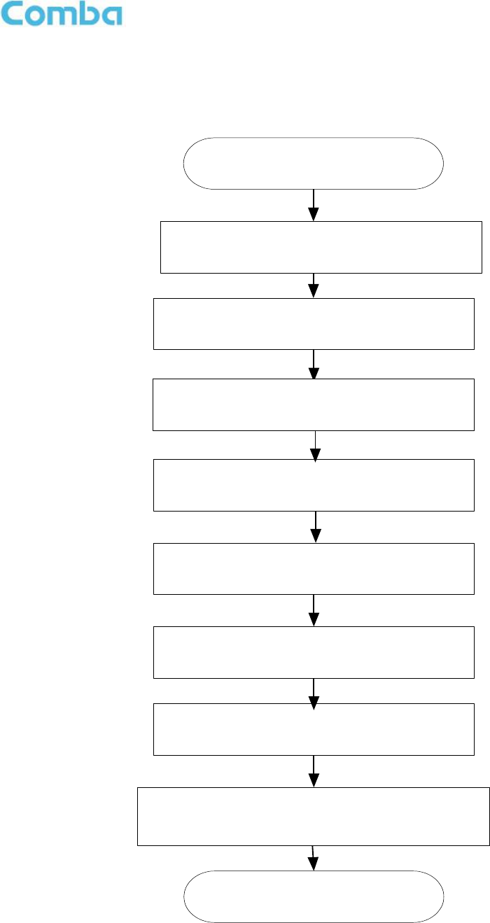
4.3 COMMISSIONING PROCEDURE
System commissioning can commence after the monitoring system has completed self initialization. The
commissioning procedure is shown below:
Connect and inquiry status
Set channel No.
Input power detection and adjust the direction of
Donor Antenna
Output power confirmation
Drive test and adjust the direction of Service
Antenna
Adjust UL ATT and confirm the call quality
Double check the status of BTS Uplink and the isolation
between Donor Antenna and Service Antenna
End
Set monitor parameters
Isolation detection
Figure 24: Commissiong Flow Chart

USER MANUAL FOR MBDA-200
ENU STATUS : 1-0-0
Copyright - refer to title page
Page 32
Table 6: Commissioning Procedure
Commissioning Tasks
Observation
1. On-line and Inquiry status
Activate the OMT Main window. The system Initialization will
completed in about 2 minutes.
Click “Connect” button to enquire the repeater’s status. Proceed if
there is no alarm; else check the failure and attend to the alarm.
2. Isolation detection
Detect isolation of service antenna and donor antenna.
3. Set Channel No.
Keep RF switch ON and set the channel number of the repeater’s
operating frequency.
4. Adjust Downlink Output
Power and align donor
antenna
Observe DL input power from measured value. Align the direction
of donor antenna until the DL input power reading is maximized.
Note: To ensure that the measured DL input power is accurate,
one should set the DL ATT to “0” before performing the check.
5. Configure [Equipment ID]
Go to [Properties Info] and set [Equipment ID].
6. Comm. Config
Enable the power supply by selecting “On” in [RF] -> [Switch]; go to
[Properties Info.] -> [Comm. Config.] and set OMC Phones No. ,
the service No. of SMSC, Report Mode.
7. Select Monitoring
Parameters
Select the equipment controlled and monitored parameters.
If the external devices are connected to the equipment for
management, please enable in the [External Alarm Info.] Interface.
8. Test coverage area field
intensity and adjust
service antenna.
Use test-handset to verify field intensity within the coverage area. If
needed, realign the service antenna to achieve the desired
coverage.
Note: If during operation, the equipment gain could not be set to
maximmum or the output power is not high enough due to
insufficient donor and service antennas isolation, then the
antennas’ position should be changed to increase isolation. If the
output power is too high and ALC is activated, then adjust the DL
ATT to achieve optimal DL Gain.
9. Verify UL gain and ensure
test call produces good
voice quality and there is
no interfering BTS
Adjust UL gain and perform test calls. Typically, the UL gain is set
around 5dB less than DL gain. Perform test calls in the coverage
area while adjusting UL gain if required.
Note: If the repeater is near the BTS and the test call performance
is poor, this may be due to UL noise interference to the BTS. Users
can calculate and determine if the repeater UL noise will interfere
with the BTS.
Verify again that there is no unacceptable interference to BTS.
End of Section
5 WEB GUI
mBDA can be monitored and controlled by WEB GUI, follow below contents to achieve system parameter
setting and commissioning.
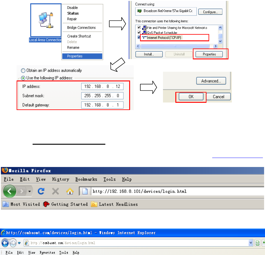
5.1 WEB GUI CONNECTION
Step 1: Connect PMU OMT port to PC RJ45 port with the supplied Ethernet cable to set up a physical
connection.
Step 2: Go to laptop Control Panel\Network and Internet\Local Area Connection. Right click it and click
Properties. Then follow the steps shown in figure below.
Figure 25: PC IP Address Setting
Step 3: Open browser (browser IE7.0, IE8.0, Chrome or Firefox, suggest disply resolution is 1024×768),
input Web GUI IP address: 192.168.8.101, click [Enter].
NOTE: DHCP and DNS are also available to login Web GUI. The domain name is: www.combaomt.com.
Figure 26: Input IP Address
Figure 27: Input Domain Name
USER MANUAL FOR MBDA-200
ENU STATUS : 1-0-0
Copyright - refer to title page
Page 34
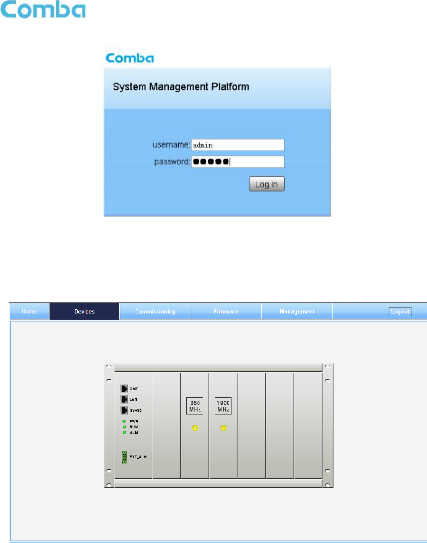
Step 2: Input User Name: admin; Password (default password: admin). Click [Log in].
Figure 28: Input User Name and Password
5.2 WEB GUI INTRODUCTION
After log in, the Web GUI main screen will appear.
Figure 29: Web GUI Main Screen
On Comba Web GUI Home Screen, there are four Menu bars:
[Devices], [Commissioning], [Firmware] and [Management].
5.2.1 [DEVICES]
The [Devices] Screen shows the actual active modules of mBDA.
USER MANUAL FOR MBDA-200
ENU STATUS : 1-0-0
Copyright - refer to title page
Page 35
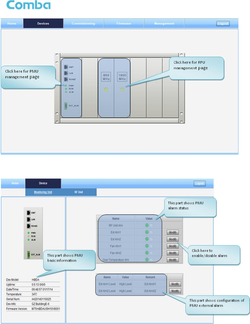
Figure 30: [Devices] Sceen
PMU Main Management Screen
Figure 31: Power & Monitoring Unit
USER MANUAL FOR MBDA-200
ENU STATUS : 1-0-0
Copyright - refer to title page
Page 36
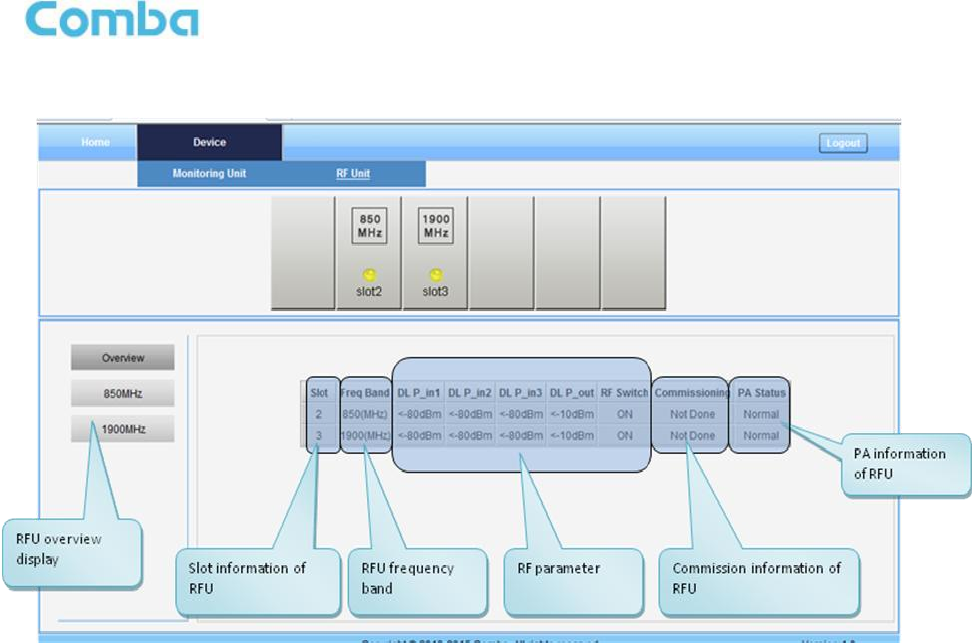
RF Unit Management Screen
Figure 32: RF Unit
NOTE: There are three statuses for PA Service: Normal, Recovery and Shutdown. If PA output power
or reflected power exceeds the threshold, software will trigger Recovery:
It will reset PA and then re-detect the PA output power and reflected power, if they are normal, the PA
Service Status will turn to Normal, if PA output power or reflected power is still over the threshold, PA
Service Status will turn to Recovery again.
If PA output power or reflected power is still over the threshold after six times of PA Recovery, PA
Service status will be Shutdown which will need to be reset manually. Reset at Management > PA
Reset.
USER MANUAL FOR MBDA-200
ENU STATUS : 1-0-0
Copyright - refer to title page
Page 37
Figure 33: RF Unit Detail Information
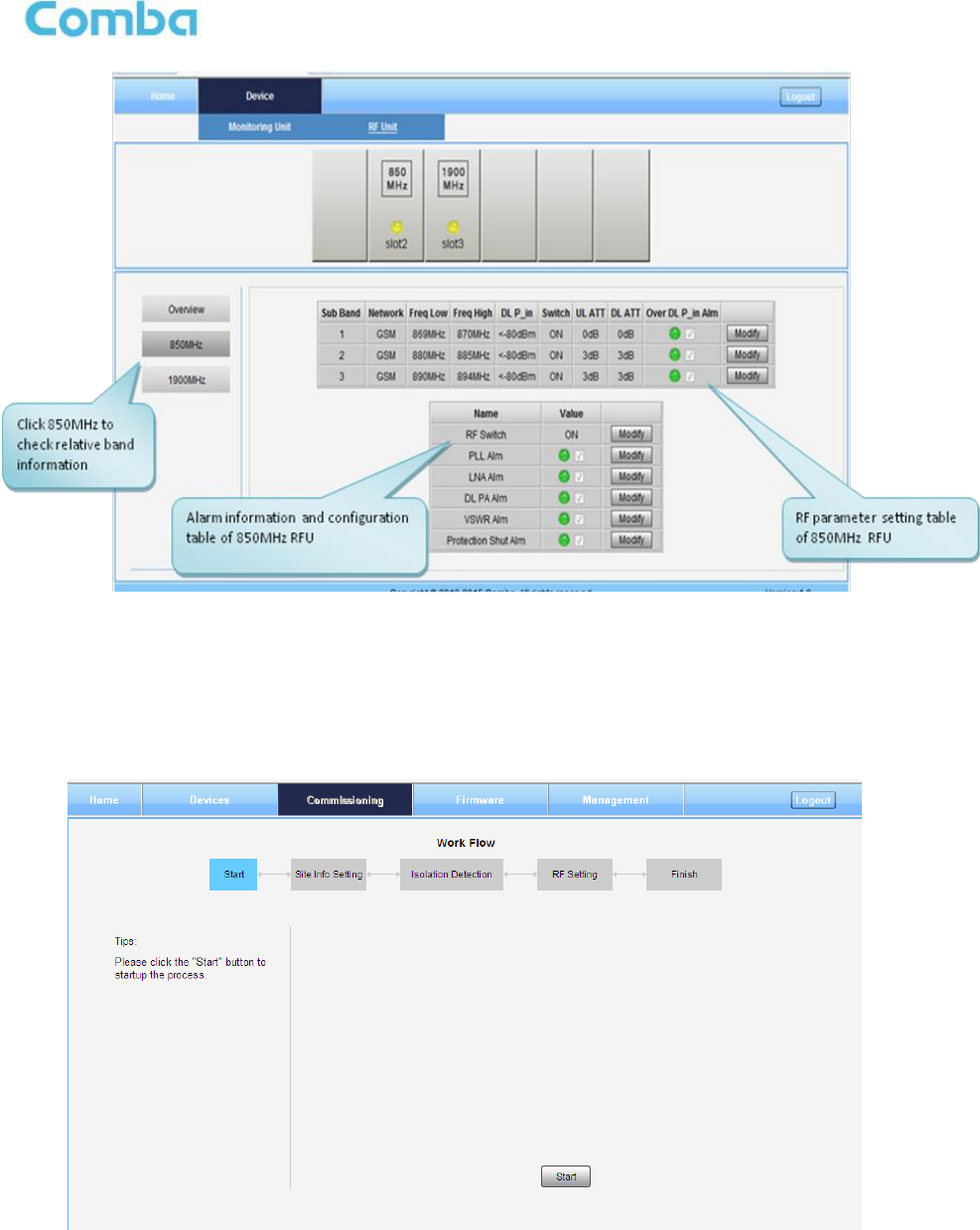
5.2.2 [COMMISSIONING]
A work flow of the commissioning process is shown on [Commissioning] Screen. Click the [Start] button,
the software will guide you through the commissioning step by step. For details, please refer to chapter
5.3.
Figure 34: [Commissioning] Screen
USER MANUAL FOR MBDA-200
ENU STATUS : 1-0-0
Copyright - refer to title page
Page 38
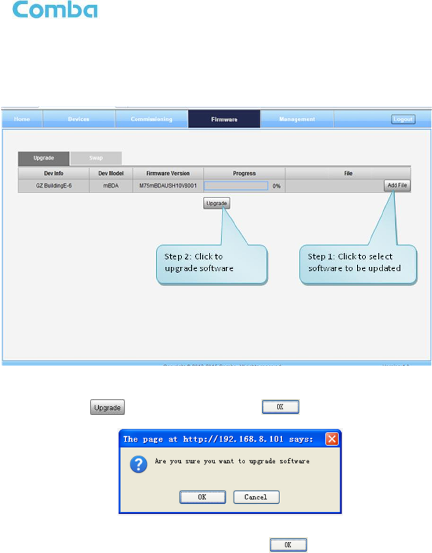
5.2.3 [FIRMWARE]
There are two functions on the [Firmware] bar: [upgrade] and [swap]. [Upgrade] is used to upgrade
software, and [Swap] is to replace current firmware version to the previous one.
Follow steps shown in below figure to upgrade firmware.
Figure 35: [Firmware] Screen – Upgrade
Step 4: After clicking , a window will pop up and click .
Figure 36: [Firmware] Screen – Pop-up Window 1
Step 5: Wait for 2~4 minutes while mBDA is being reset. Click to continue.
Step 6: Clear browsing history and cookies from browser.
NOTE: For PMU software upgrade, users need to re-login Web GUI after reset is done.
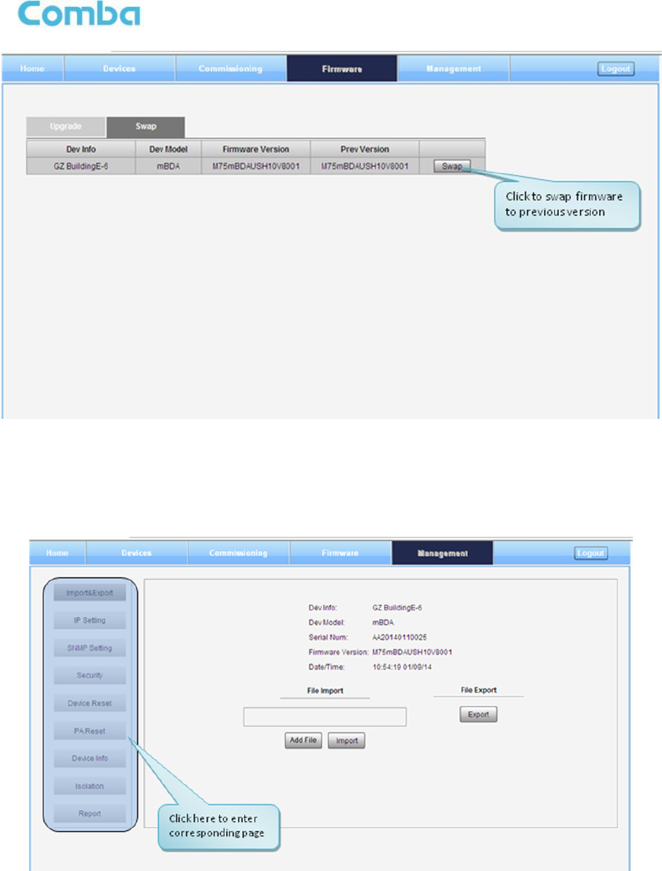
Follow steps shown in below figure to Swap firmware.
USER MANUAL FOR MBDA-200
ENU STATUS : 1-0-0
Copyright - refer to title page
Page 39
Figure 37: [Firmware] Screen - Swap
5.2.4 [MANAGEMENT]
Other parameters can be configured on [Management] Screen.
Figure 38: [Management] Sceen
There are nine function bars list in the left side of the [Mangement] Screen. Below figures are the
introduction of each function bar.
USER MANUAL FOR MBDA-200
ENU STATUS : 1-0-0
Copyright - refer to title page
Page 40
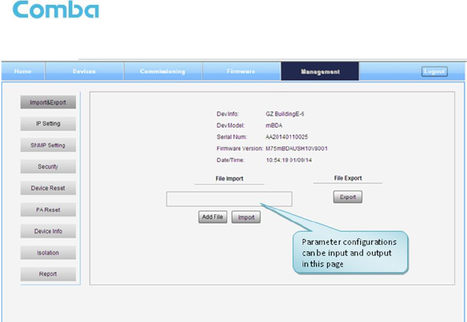
Inport&Export
Figure 39: Management – Import&Export
The parameters that can be import/export as below: sub band, alarm enable, ATT value, RF switch, DL
output power and so on.
Import and Export can help users quickly configure mBDA parameters. For example, if one mBDA
finished configuration, users can export its parameters and save as a file in PC, and then import this file to
other mBDA to fast finish the device parameter setting.
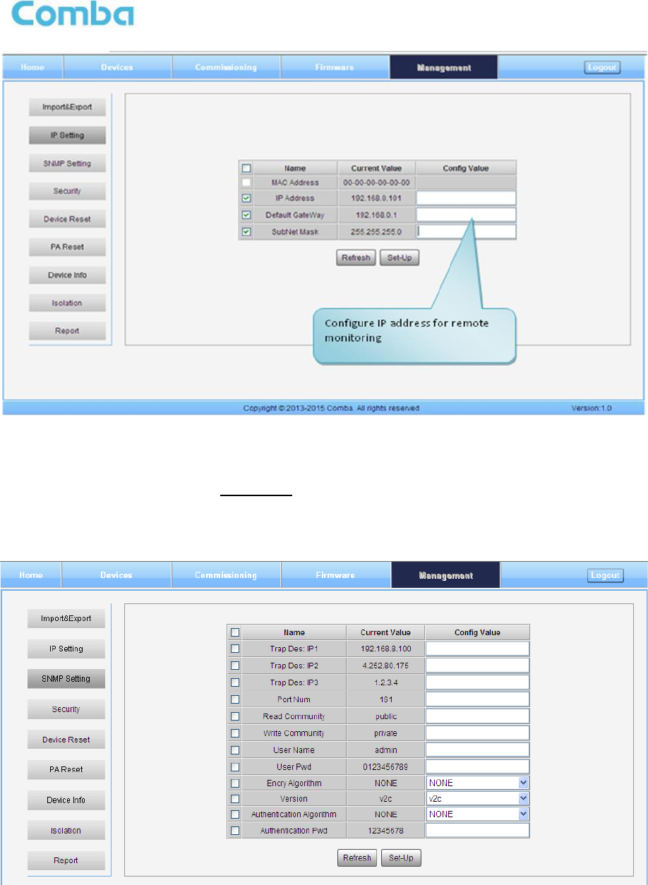
IP Setting
USER MANUAL FOR MBDA-200
ENU STATUS : 1-0-0
Copyright - refer to title page
Page 41
Figure 40: Management – IP Setting
Note: For remote monitoring, the IP Address must be set correctly according to the location IP of remote
connection. If more than one equipment is connected to the public network through the same router, the
router’s local IP CANNOT be set as 192.168.8.*.
SNMP Setting
Figure 41: Management – SNMP Setting
USER MANUAL FOR MBDA-200
ENU STATUS : 1-0-0
Copyright - refer to title page
Page 42
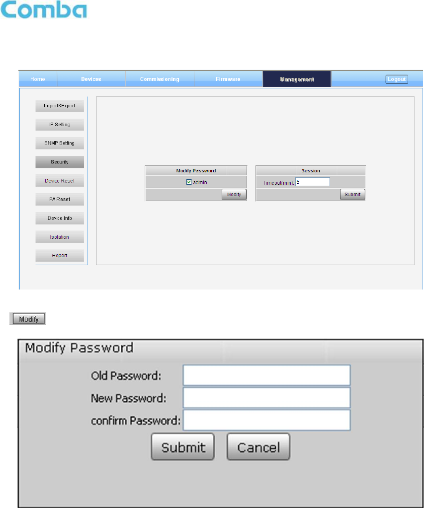
Security
Figure 42: Management – Security
Click , [Modify Password] window will pop-up.
Figure 43: Modify Password
Note: Username cannot be modified.
USER MANUAL FOR MBDA-200
ENU STATUS : 1-0-0
Copyright - refer to title page
Page 43
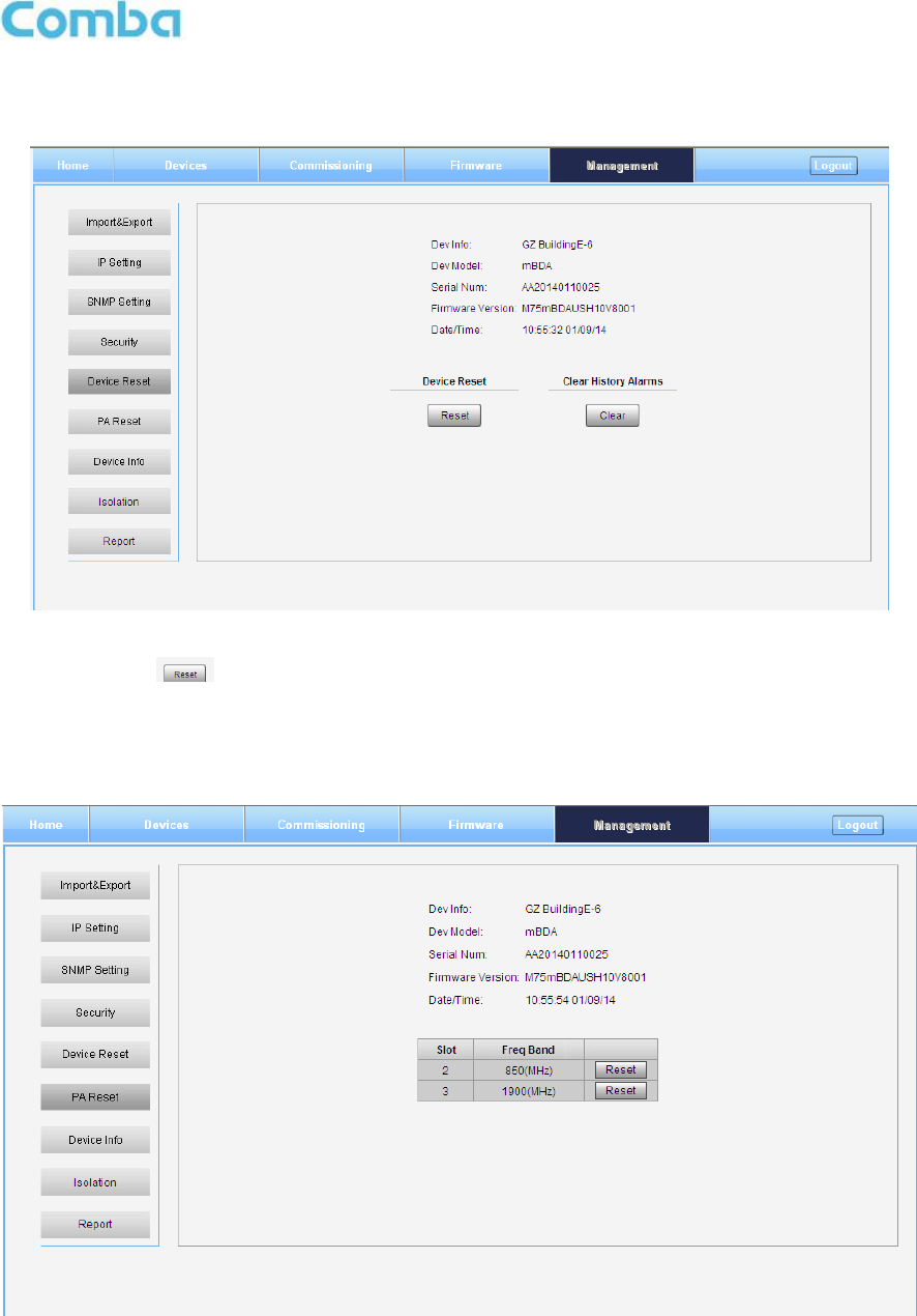
Device Reset
Figure 44: Management – Device Reset
Note: If users click , all the parameter and alarm will set to factory default value. Device Reset
process will last about 2~4 minutes. For PMU monitor reset, users need to re-login WEB GUI.
PA Reset
Figure 45: Management – PA Reset
Note: PA will be turned off by software when PA output power or (VSWR) reflected power is exceed the
threshold. Users need to reset PA after debugging.
USER MANUAL FOR MBDA-200
ENU STATUS : 1-0-0
Copyright - refer to title page
Page 44
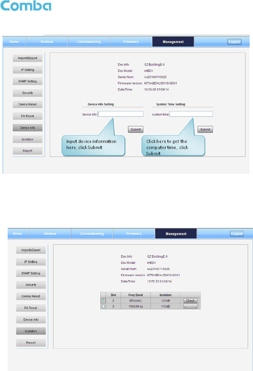
Device Info
Figure 46: Management – Device Info
Note: Users can input maximum 30 bytes characters in Device Info.
Isolation
Figure 47: Management – Isolation
Note: This Step is the same as step3 of [Commissioning]. Users can check isolation again by clicking
Check button.
USER MANUAL FOR MBDA-200
ENU STATUS : 1-0-0
Copyright - refer to title page
Page 45
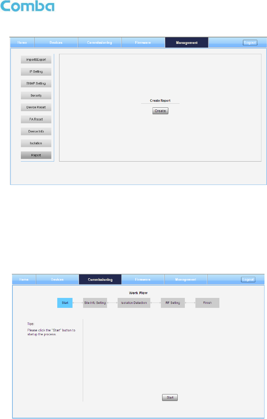
Report
Figure 48: Management – Report
Note: Click Create to create report (The report cann’t create in IE browser.) and make sure the computer
has installed PDF Reader software. If no, users will see nothing.
5.3 COMMISSIONING PROCEDURE
To complete the installation and commissioning, users need to follow the steps below.
Step 1: Click Menu bar [Commissioning] on home screen, a work flow will show up.
Figure 49: Commissioning Procedure - Start
USER MANUAL FOR MBDA-200
ENU STATUS : 1-0-0
Copyright - refer to title page
Page 46
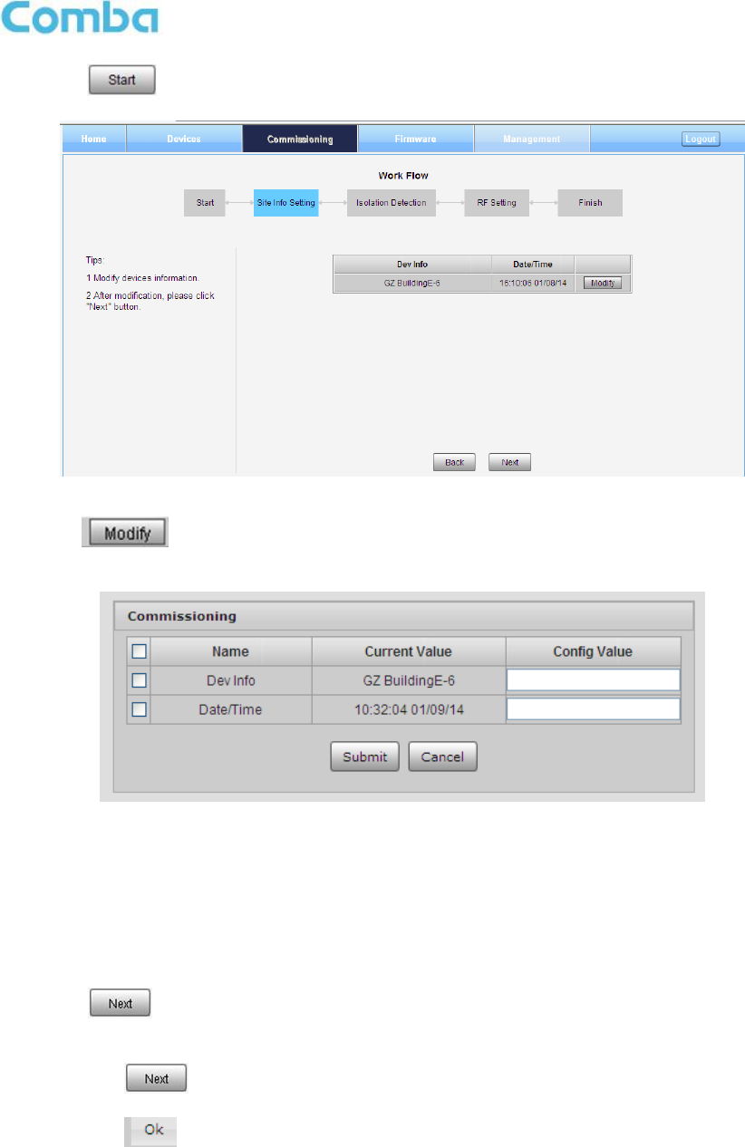
Step 2: Click to start the process.
Figure 50: Commissioning Procedure – Site Info. Setting
Step 3: Click , users can set the site information.
Figure 51: Dev Info & Date/Time
Dev Info mainly used to record device location and Date/Time provid a time reference. Click the Config
Value of Date/Time, will update Date/time automatically.
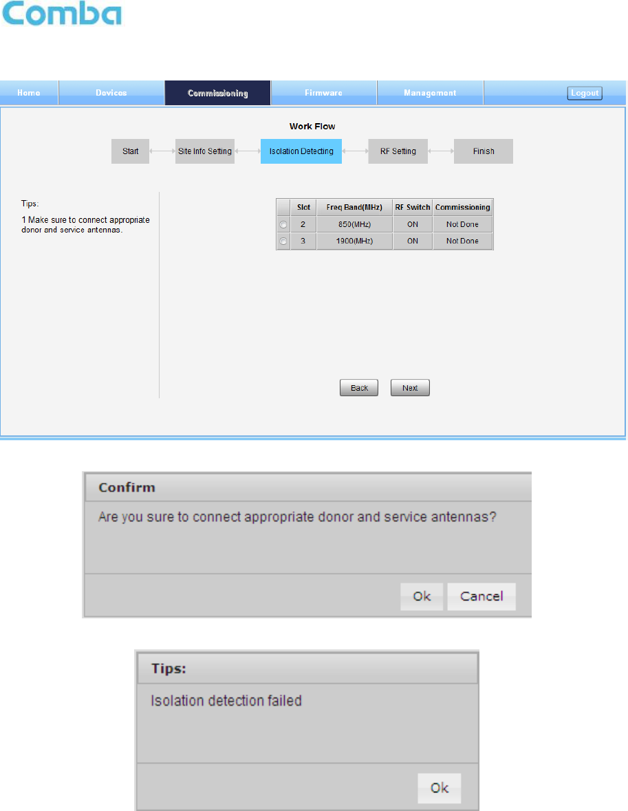
NOTE: Make sure the device is connected with appropriate donor and service antennas before
proceeding to step 4.
Step 4: Click to enter to Isolation Detection Screen shown as Figure 52.
Select a frequency band (RFU) that need to commission.
Click to start Isolation Detecting, then [Confirm] window will pop-up shown as Figure
53.
Click to continue. If isolation detection success, the process will go to RF Settiing
Screen shown as Figure 55. If failed, a Tips window will pop-up shown as Figure 54, users
need to check whether the system isolation is very weak.
USER MANUAL FOR MBDA-200
ENU STATUS : 1-0-0
Copyright - refer to title page
Page 47
NOTE: At the end of first frequency band commissioning, user can start other frequency band
commission.
Figure 52: Commissioning Procedure – Isolation Detective
Figure 53: Commissioning Procedure – Isolation Detective Confirm
Figure 54: Commissioning Procedure –Isolation Detection Failed
USER MANUAL FOR MBDA-200
ENU STATUS : 1-0-0
Copyright - refer to title page
Page 48
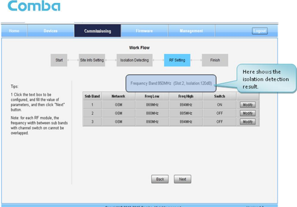
Figure 55: Commissioning Procedure –Isolation Detection Finish
Step 5: RF Setting Screen for setting subband bandwidths and switchs.
USER MANUAL FOR MBDA-200
ENU STATUS : 1-0-0
Copyright - refer to title page
Page 49
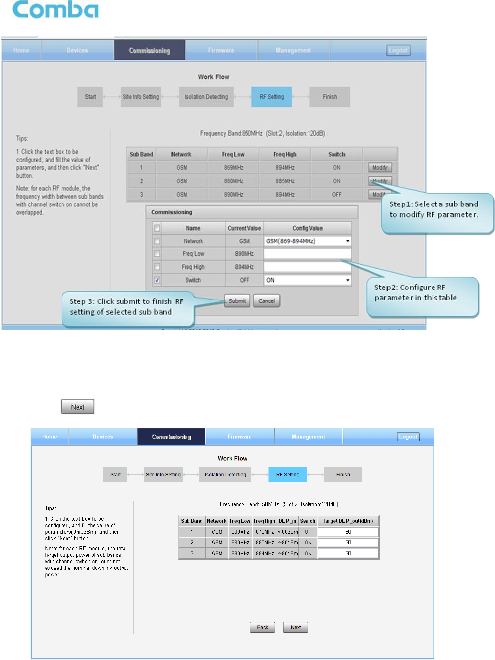
Figure 56: Commissioning Procedure – Subband bandwidth and Switch Setting
NOTE: For each RF module, the 3 subband bandwidth setting should not be overlap each other, if yes,
only 1 subband can be turn on, other overlap subband is forbided to switch on by equipment.
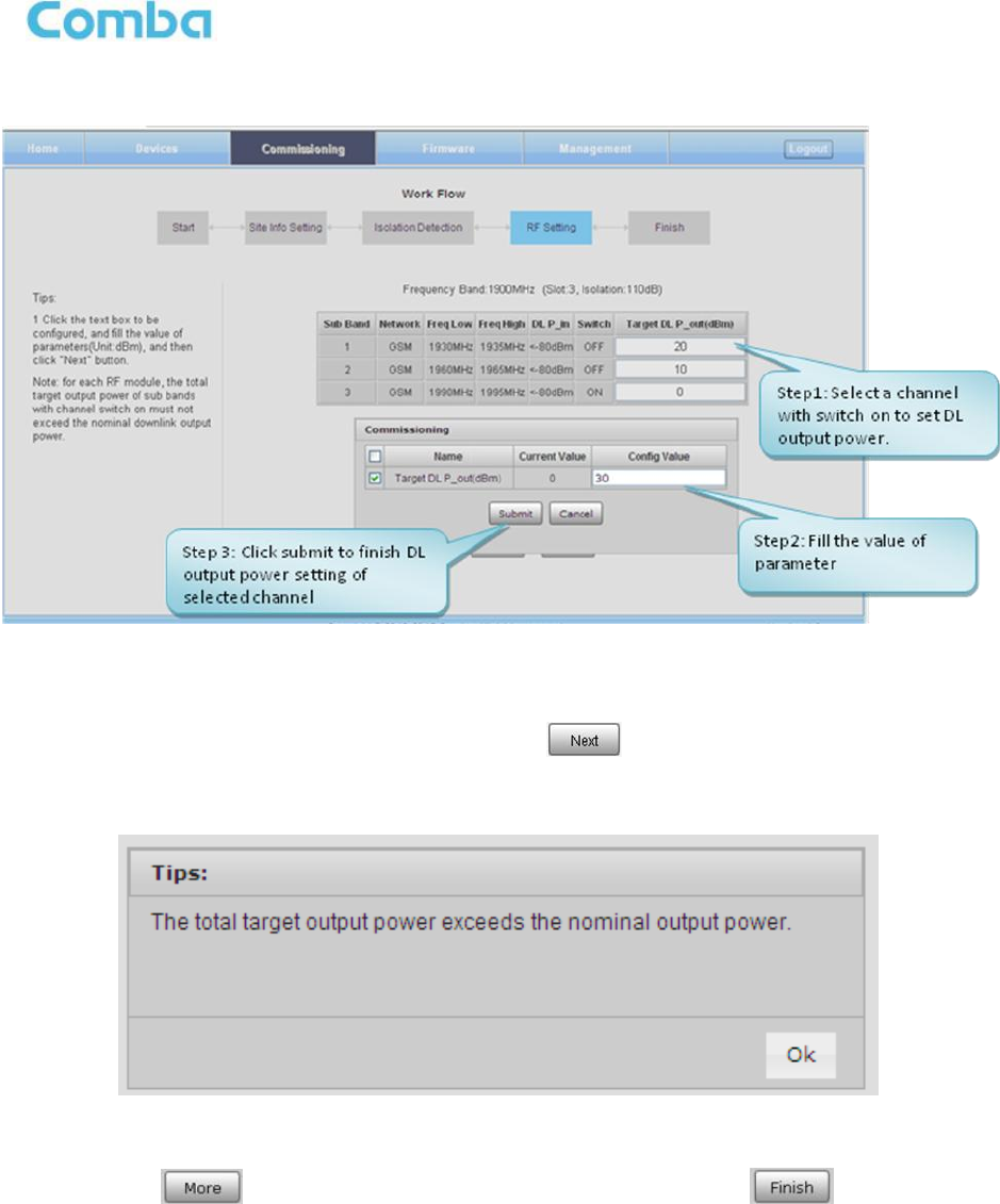
Step 6: Click to enter to DL output power setting after finishing subband bandwidths and switchs
setting.
Figure 57: Commissioning Procedure – DL Output Power Setting Screen
USER MANUAL FOR MBDA-200
ENU STATUS : 1-0-0
Copyright - refer to title page
Page 50
Figure 58: Commissioning Procedure – DL Output Power Setting
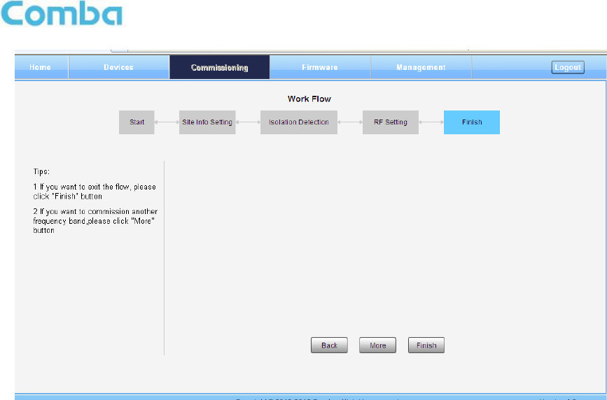
NOTE: For each RF module, the total target output power of all subbands which channel switch is on
must not exceed the nominal downlink output power (27, 30, 33dBm); if yes, Tips window will pop-up
shown as Figure 59. Finish the output power setting, click button , go to Finish Screen shown as
Figure 60.
Figure 59: DL Output Power Over Exceed
Step 7: Click to commission other RFUs parameters. Click to finish the
commissioning.
USER MANUAL FOR MBDA-200
ENU STATUS : 1-0-0
Copyright - refer to title page
Page 51
Figure 60: Commissioning Procedure – Finish
End of Section

USER MANUAL FOR MBDA-200
ENU STATUS : 1-0-0
Copyright - refer to title page
Page 52
6 MAINTENANCE
The mBDA is designed for trouble-free operation and generally does not need maintenance. Maintenance
activities should only be carried out by trained personnel.
The equipment operation status can be observed remotely through OMC.
Periodic inspection of the repeater equipment(s) is recommended, the recommended tasks includes:
Inspect and record operation status and output power of the repeater from OMC or OMT.
Verify the direction and position of antennas. Re-align if necessary.
Make sure the cable gland and sealing on the RF cable connectors are not damaged.
Verify lightning and grounding protection is in good condition.
End of Section

USER MANUAL FOR MBDA-200
ENU STATUS : 1-0-0
Copyright - refer to title page
Page 53
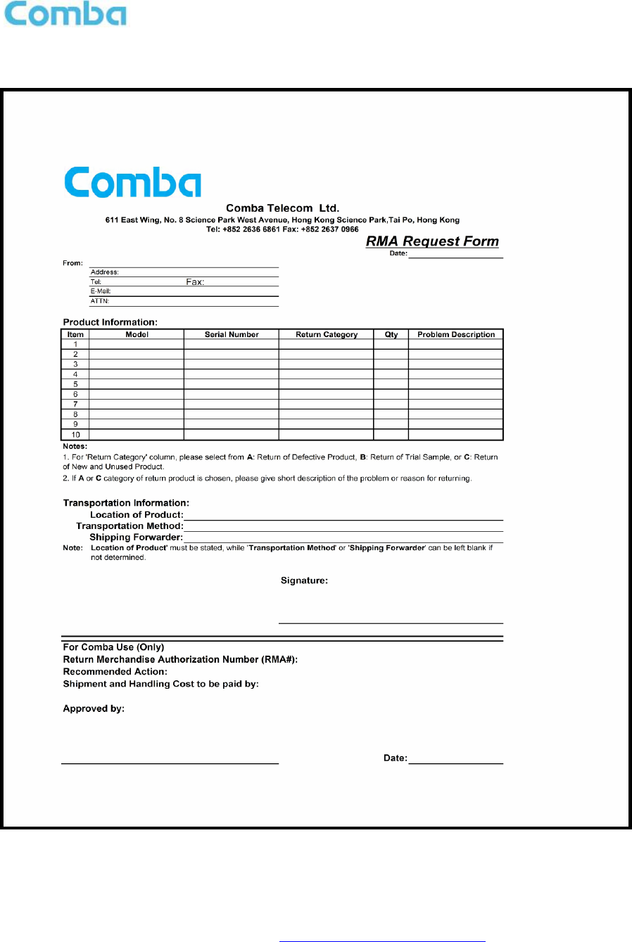
7 APPENDICES
7.1 APPENDIX A: TOOLS FOR INSTALLATION AND MAINTENANCE
The following tools (not included in package) are required for installation or routine maintenance:
Power Drill (for wall mount)
Adjustable Wrench (0.31 inch~0.79 inch)
Philips Screwdriver
Allen wrench (M6)
Signal generator support output power 10dBm.
Site Master

USER MANUAL FOR MBDA-200
ENU STATUS : 1-0-0
Copyright - refer to title page
Page 55