Comba Telecom TC-2000 AWS Base Station Power Amplifier User Manual TC 2000 QI 1 1 1 for FCCx
Comba Telecom Ltd. AWS Base Station Power Amplifier TC 2000 QI 1 1 1 for FCCx
UserManual.wiki
>
Comba Telecom
>
TC 2000 User Manual
PX8TC-2000 User Manual Rev1
Navigation menu
Upload a User Manual
Namespaces
Wiki Guide
HTML
PDF
Info
Views
User Manual
Discussion / Help
Navigation
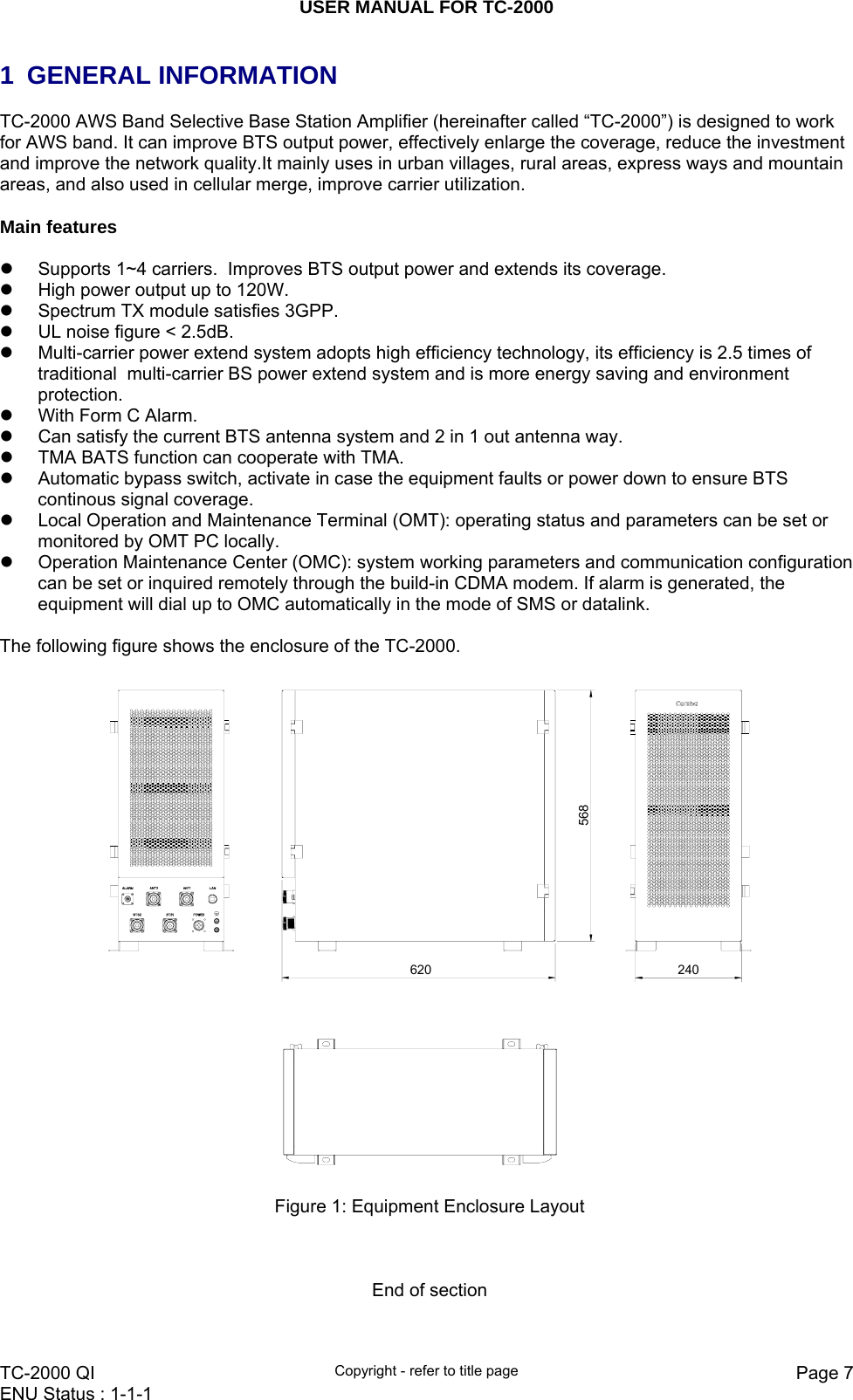
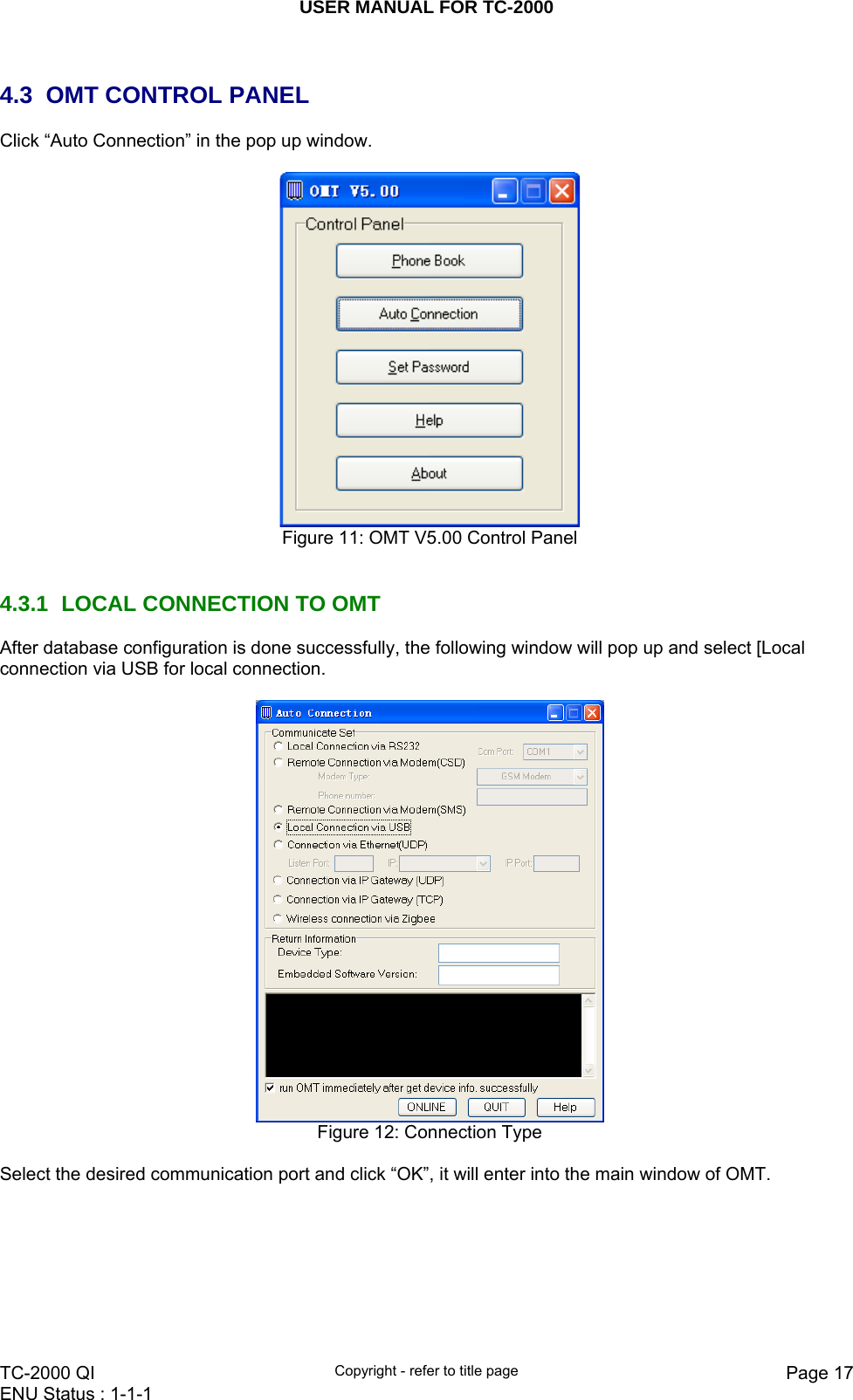
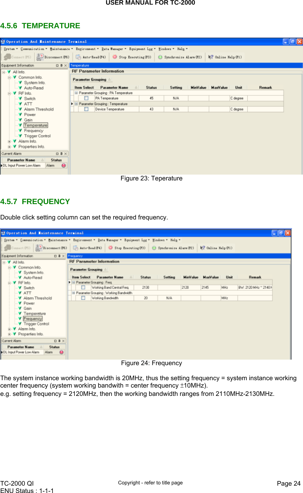
![USER MANUAL FOR TC-2000 TC-2000 QI Copyright - refer to title page Page 16ENU Status : 1-1-1 4 OMT The equipment can be monitored and controlled by OMT software running on a local PC with local commissioning cable, remote connection to the equipment via wireless GSM network. z OMT software running on a local PC with serial connection to the equipment. z OMC (optional) software with remote connection to the equipment over wireless GSM network. This chapter is to introduce how to apply local and remote connection to OMT for the first installation, for the detailed OMT information, please refer to OMT user manual and other references. Notice: The OMC software with remote connection to the equipment over wireless GSM network is optional for customers. 4.1 LOCAL AND REMOTE CONNECTIONS TO OMT After installing OMT software on the PC, connection to the equipment can be done locally or remotely. Double click the OMT explorer icon, the OMT Explorer main screen window will appear. 4.2 OMT LOGIN When starting OMT, the following figure will show. Figure 10: OMT Login The default password is 888888.User can change it in the [set password] window.](https://usermanual.wiki/Comba-Telecom/TC-2000/User-Guide-1629988-Page-16.png)
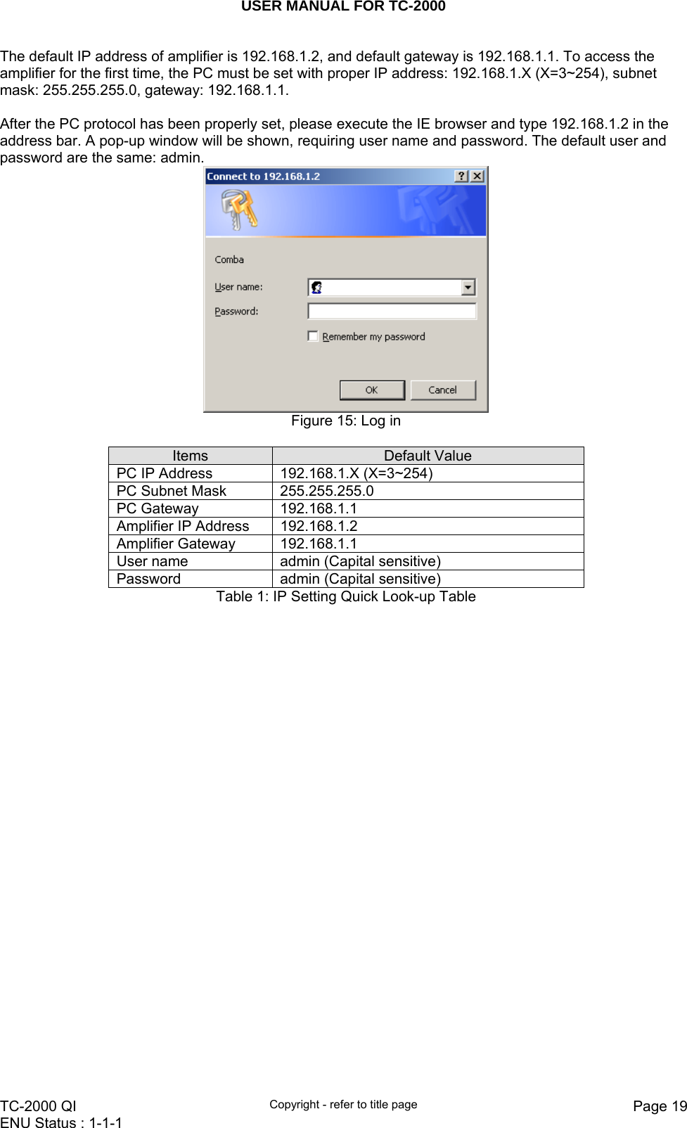
![USER MANUAL FOR TC-2000 TC-2000 QI Copyright - refer to title page Page 18ENU Status : 1-1-1 4.3.2 REMOTE CONNECTION TO OMT If remote connection is needed, users can select [Remote connection via modem] in connection type window. Select desired serial port and click “OK” in [Serial Port Configuration] window to go to OMT main window and start modem initialization. Click “connect” and the [Remote Connection] window will show up. Figure 13: Remote Connection Config: Enter the correct phone number (Users don't have to enter the password) and click “connect”, it will be connected remotely. Notice: Please enable the SIM card to support Circuit Switch Data. 4.3.3 CONNECTION FROM PC TO EQUIPMENT Before accessing to the OMT, physical connection between the OMT software and the equipment must be made. A straight-through RJ45 cable shall be applied for the connection. In order to access to equipment by IP protocol, the PC must be set with proper IP address, subnet mask and gateway. Figure 14: PC Protocol Setting](https://usermanual.wiki/Comba-Telecom/TC-2000/User-Guide-1629988-Page-18.png)
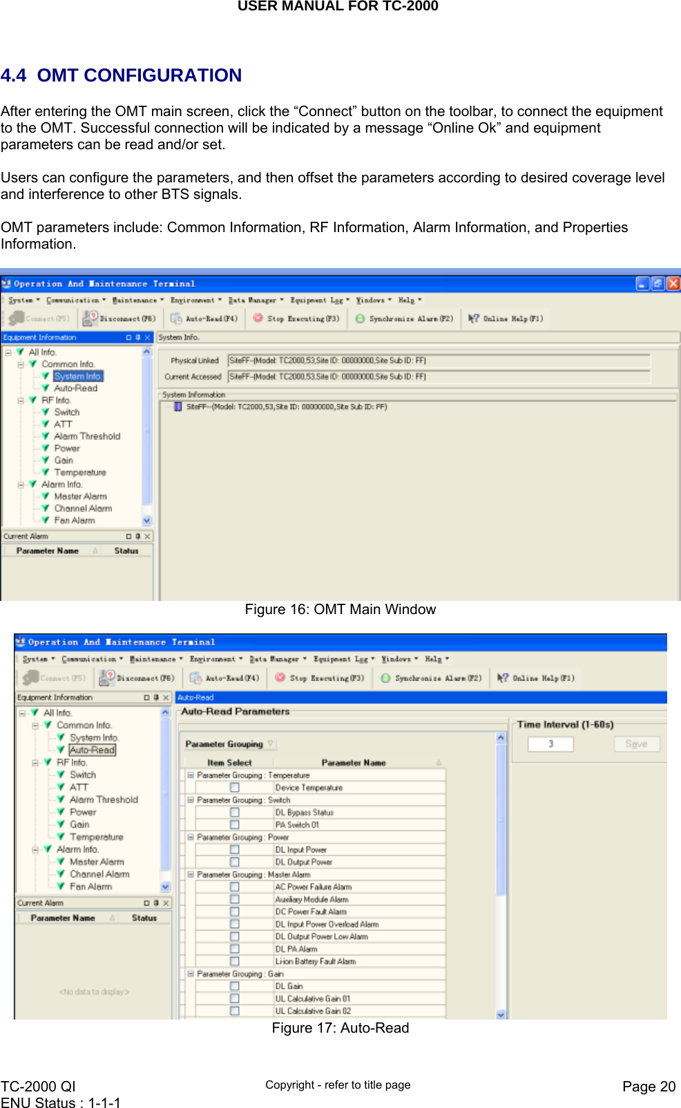
![USER MANUAL FOR TC-2000 TC-2000 QI Copyright - refer to title page Page 21ENU Status : 1-1-1 4.5 RF PARAMETER It is recommended to configure the following RF parameters for the first installation. 4.5.1 SWITCH Switch is to enable/disable power for internal PA modules. When user checks and sets non-RF parameters, such as checking physical antenna connection, switching off will disable equipment power temporarily to protect PA in operation. Below is a demonstration by single PA module. Figure 18: Switch Config: Select the required state in setting columns of RF information window for RF switch, then press [Enter] or [Config] button to finish the configuration operation. 4.5.2 ATT Figure 19: ATT](https://usermanual.wiki/Comba-Telecom/TC-2000/User-Guide-1629988-Page-21.png)
![USER MANUAL FOR TC-2000 TC-2000 QI Copyright - refer to title page Page 22ENU Status : 1-1-1 Config: Select the required value in setting columns of RF information window for ATT, and press [Enter] or [Config] button to finish the configuration operation. 4.5.3 ALARM THRESHOLD Alarm Threshold includes Power threshold, Temperature threshold and VSWR threshold. Users can set alarm threshold according to the specific situation. If the measured value is lower than the threshold lower limit or more than the threshold upper limit, the appropriate alarm will be generated. Figure 20: Alarm Threshold Config: Enter the required value in setting columns of RF information window for Alarm threshold, and press [Enter] or [Config] button to finish the configuration operation. 4.5.4 POWER Power is referring to the reading of downlink input/output power.](https://usermanual.wiki/Comba-Telecom/TC-2000/User-Guide-1629988-Page-22.png)
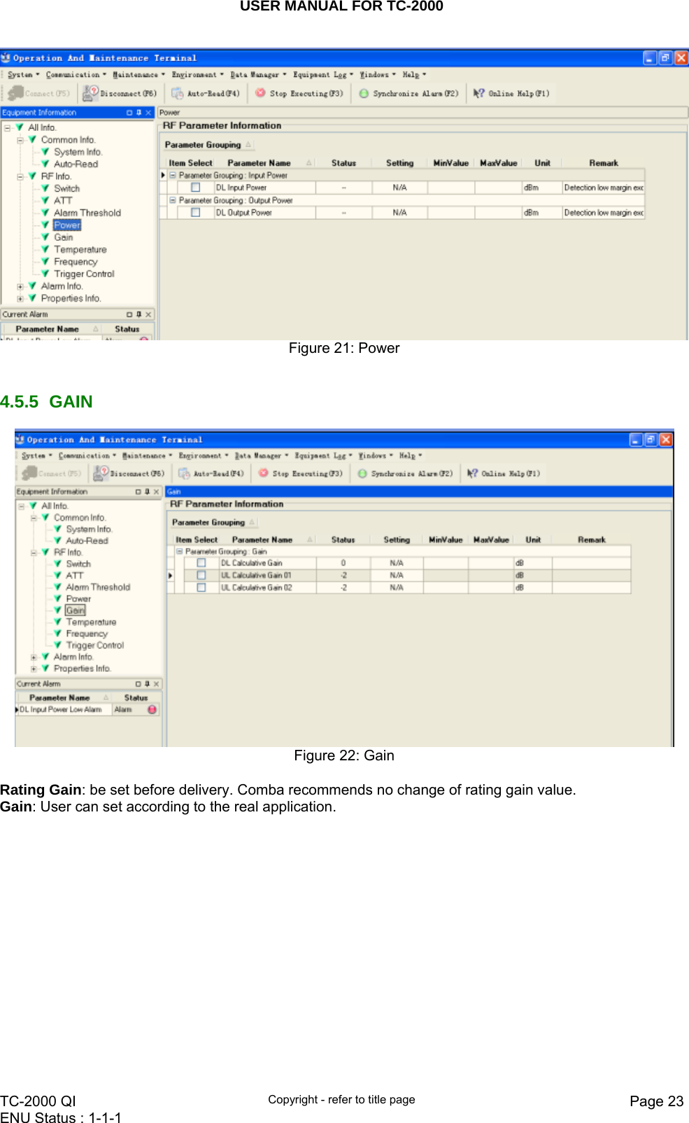
![USER MANUAL FOR TC-2000 TC-2000 QI Copyright - refer to title page Page 25ENU Status : 1-1-1 4.5.8 TRIGGER CONTROL Click SET can reset MCPA. Figure 25: Trigger Control 4.6 ALARM INFO 4.6.1 MASTER ALARM Alarm information operation is to select alarm parameters for monitoring. Alarm parameters include Master Alarm, Channel Alarm and Fan Alarm. Click any tree node in [Alarm Info] group, [Alarm Parameter Information] window will appear in the right side. The picture below shows the master alarm information. Figure 26: Master Alarm](https://usermanual.wiki/Comba-Telecom/TC-2000/User-Guide-1629988-Page-25.png)
![USER MANUAL FOR TC-2000 TC-2000 QI Copyright - refer to title page Page 26ENU Status : 1-1-1 Figure 27: Channel Alarm Figure 28: Fan Alarm Config: Tick the check box of [Item select] and [Enable] of the desired parameters and click [config] button to finish configuration operation. Notice: [Enable] box is to enable the alarm monitoring for system. Only if users enable the alarm by ticking the [Enable] box, the alarms can be monitored by the OMT/OMC. On the MCU, if any alarm is generated and this alarm is also enabled in [Enable] box, LED ALM turns RED; while it is OFF when normal working. On the OMT/OMC window, [Alarm Status] indicator keeps GREEN if no alarm and turns RED if an alarm is generated. Alarm report can be set, users can allow or prohit the report. When alarm happens, if it is already inquired, alarm will not report; if not, alarm will dial up to OMC automatically in the mode of SMS or datalink till OMC receive the alarm and reply; if the device hasn’t received and replyed, then wait 3min and redial to OMC 3 times continuously, if still no reponse, report again after 3 hours.](https://usermanual.wiki/Comba-Telecom/TC-2000/User-Guide-1629988-Page-26.png)
![USER MANUAL FOR TC-2000 TC-2000 QI Copyright - refer to title page Page 27ENU Status : 1-1-1 The device has FORM C alarm port, specific definition as follows: Adopt 9-pin CPC connector (XM22K09K), supplies battery arlarm PA faulty alarm and bypass alarm. Terminal defined as: Pin number Name Explanation 1 DC_NO Power alarm open terminal 2 DC_COM Power alarm public terminal 3 DC_NC Power alarm closed terminal 4 PA_NO PA alarm open terminal 5 PA_COM PA alarm public terminal 6 PA_NC PA alarm closed terninal 7 BYPASS_NO Bypass alarm open terminal 8 BYPASS_COM Bypass alarm public terminal 9 BYPASS_NC Bypass alarm closed terminal Remark: the system reset automatically every 24h, the alarm information is cleared after the reset. Method of alarm report: there is a box on the right of the alarm indicator, it is used for select alarm to OMC, users can allow or prohibit the alarm report according to actual situation. Click the box on the right of the alarm, and the box shows “√" meaning selection. Click “setting” button to set. After that, if alarm occurs, the selected alarm will dial up to OMC in the mode of SMS or datalink. Please notice that if the desired alarm is not enabled in [Enable] box, even if this alarm is generated, it keeps in GREEN in the OMT/OMC interface and LED H2 on MCU keeps OFF as well.](https://usermanual.wiki/Comba-Telecom/TC-2000/User-Guide-1629988-Page-27.png)
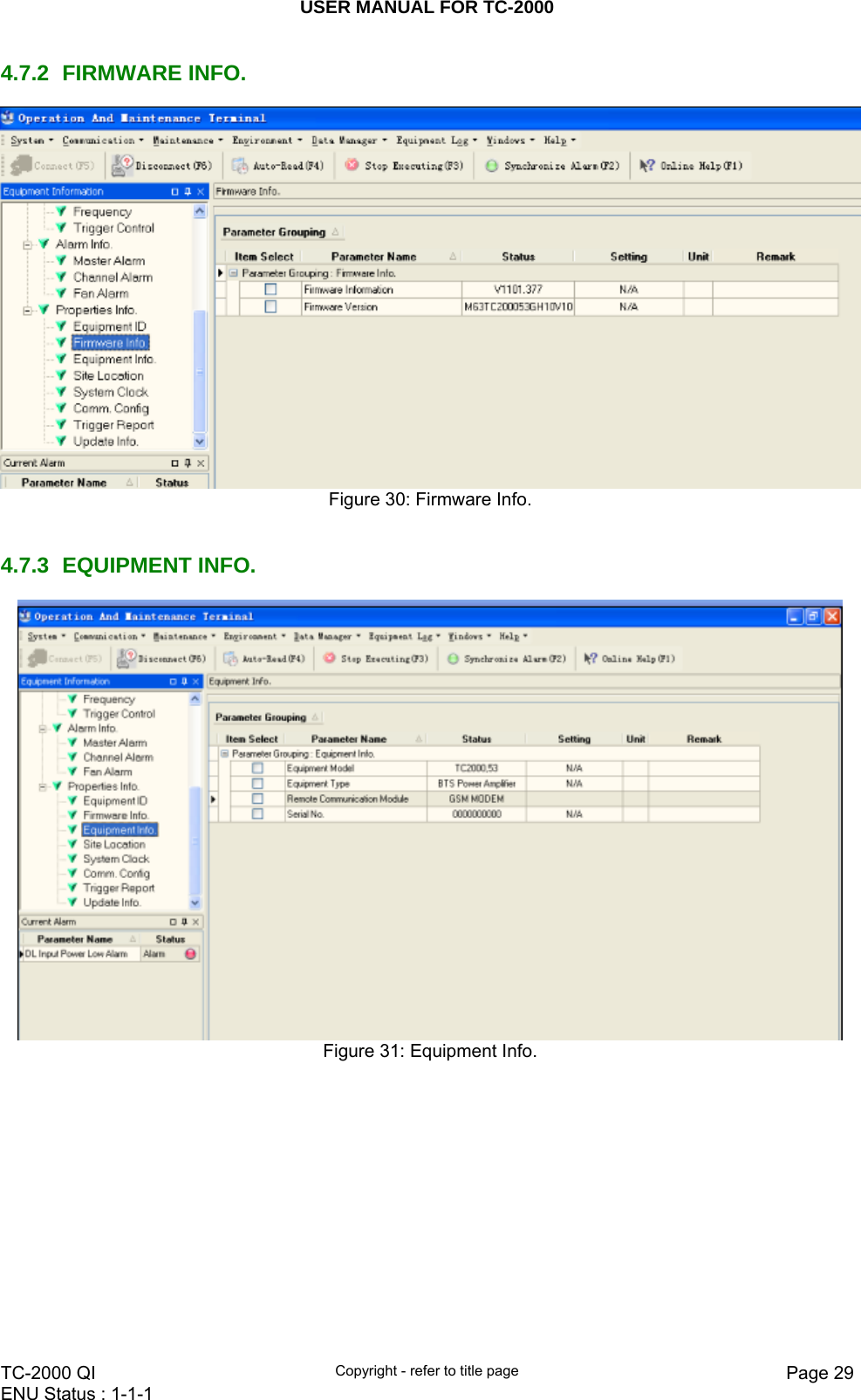
![USER MANUAL FOR TC-2000 TC-2000 QI Copyright - refer to title page Page 28ENU Status : 1-1-1 4.7 PROPERTIES INFO. 4.7.1 EQUIPMENT ID Equipment ID is to be configured after local commission has been completed, which includes Site ID, and Site Sub ID. Figure 29: Equipment ID See the table below for configuration details of each parameter. Item Description Site ID Site ID is the unique equipment identification. It is a hexadecimal string of eight characters in the range of [00000000~FFFFFFFF]. e.g. 00000000 Site Sub ID Site Sub ID is used for Master-Slave System. It is the unique identification of each Master/ Slave Unit and is a hexadecimal string of two characters in the range of [00~FF]. For the system located with single equipment, the Site Sub ID should be FF. For Master-Slave system, the Site Sub ID for Master Unit is 00, and the Site Sub ID for each Slave Unit is represented in the range of [01~FE] in ascending order. e.g. Master Site ID: 00, Slave Site ID: 01](https://usermanual.wiki/Comba-Telecom/TC-2000/User-Guide-1629988-Page-28.png)
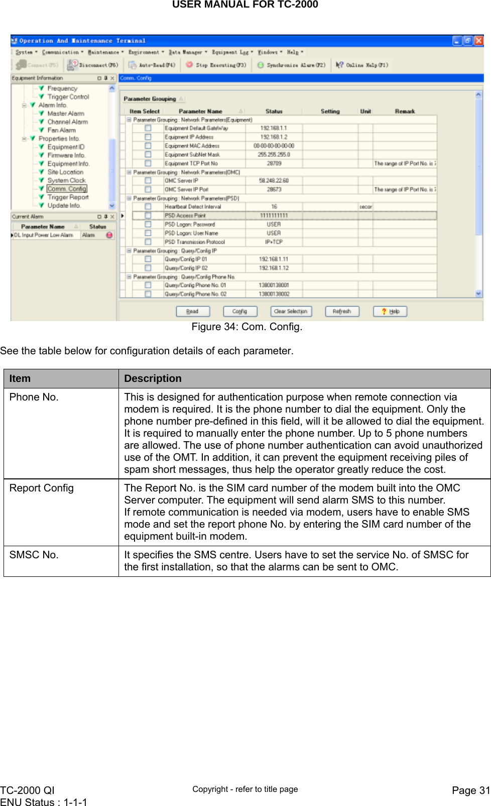
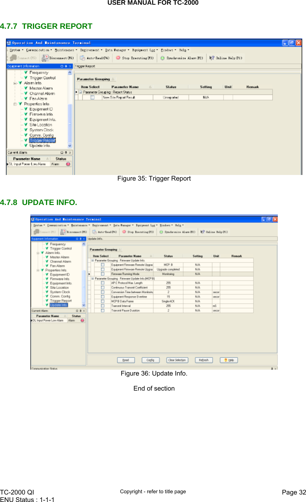
![USER MANUAL FOR TC-2000 TC-2000 QI Copyright - refer to title page Page 30ENU Status : 1-1-1 4.7.4 SITE LOCATION Figure 32: Site Location [Site Location]: input the current longitude and latitude in the blank. 4.7.5 SYSTEM CLOCK Figure 33: System Clock [System Clock]: it shows the current time/date information. It is settable. 4.7.6 COMM. CONFIG If the equipment is to be monitored by OMC software over wireless GSM / CDMA network, users must finish the [Comm. Config.] in the next step. The Comm. Config information requires to be manually entered by users after successful connection to the equipment.](https://usermanual.wiki/Comba-Telecom/TC-2000/User-Guide-1629988-Page-30.png)
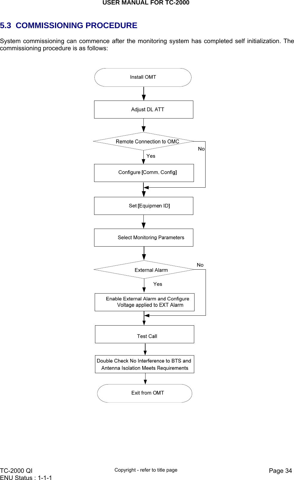
![USER MANUAL FOR TC-2000 TC-2000 QI Copyright - refer to title page Page 35ENU Status : 1-1-1 Commissioning Tasks Observation 1. Install OMT z Activate the OMT Main window. The system Initialization will completed in about 2 minutes. z Click “Connect” button to enquire the amplifier’s status. Proceed if there is no alarm; else check the failure and attend to the alarm. 2. Adjust DL ATT z Observe DL input power from measured value and adjust according accordingly via the ATT1/2 on the front panel. z Note: To ensure that the measured DL input power is accurate, one should set the DL ATT to “0” before performing the check. 3. Configure [Equipment ID] z Go to [Properties Info] and set [Equipment ID]. 4. Comm. Config z Enable the power supply by selecting “On” in [RF] -> [Switch]; go to [Properties Info.] -> [Comm. Config.] and set OMC Phones No. , the service No. of SMSC, Report Mode. 5. Select Monitoring Parameters z Select the equipment controlled and monitored parameters. z If the external devices are connected to the equipment for management, please enable in the [External Alarm Info.] Interface. 6. Test coverage area field intensity and adjust service antenna. z Use test-handset to verify field intensity within the coverage area. If needed, realign the service antenna to achieve the desired coverage. z Note: If during operation, the equipment gain could not be set to maximum or the output power is not high enough due to insufficient donor and service antennas isolation, then the antennas’ position should be changed to increase isolation. If the output power is too high and ALC is activated, then adjust the DL ATT to achieve optimal DL Gain. 7. Verify UL gain and ensure test call produces good voice quality and there is no interfering BTS z Adjust UL gain on TMA if required and perform test calls. Typically, the UL gain is set around 5dB less than DL gain. Perform test calls in the coverage area while adjusting UL gain on TMA if required. z Verify again that there is no unacceptable interference to BTS.](https://usermanual.wiki/Comba-Telecom/TC-2000/User-Guide-1629988-Page-35.png)