CommScope Technologies 800002-1 Licensed Base Station User Manual IP RN 8000 I C Guide
Airvana, LP Licensed Base Station IP RN 8000 I C Guide
UserManual.wiki
>
CommScope Technologies
>
800002-1 User Manual
>
Manual 1
Contents
1.
Manual 1
2.
Manual 2
Manual 1
Navigation menu
Upload a User Manual
Namespaces
Wiki Guide
HTML
PDF
Info
Views
User Manual
Discussion / Help
Navigation
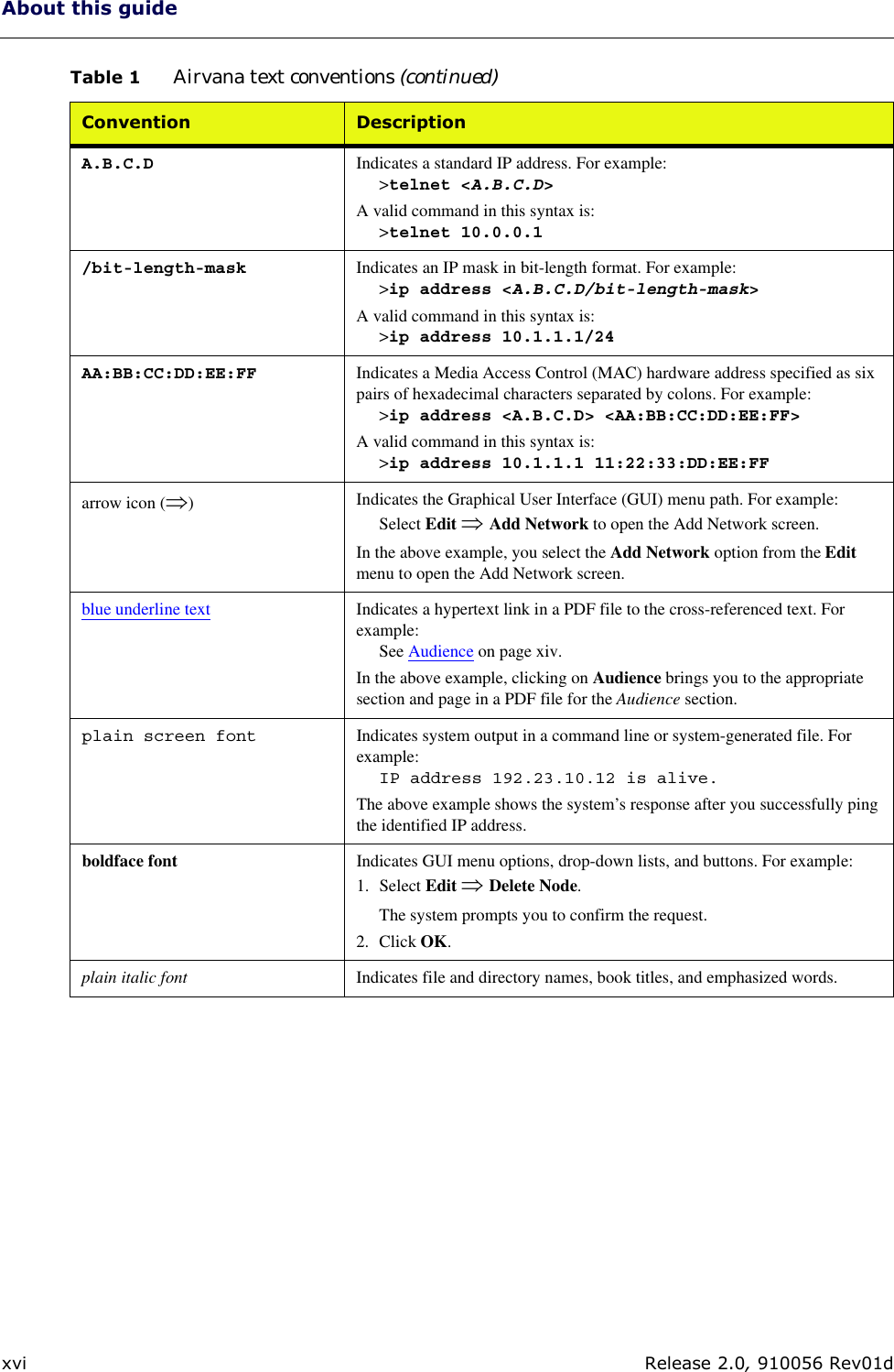
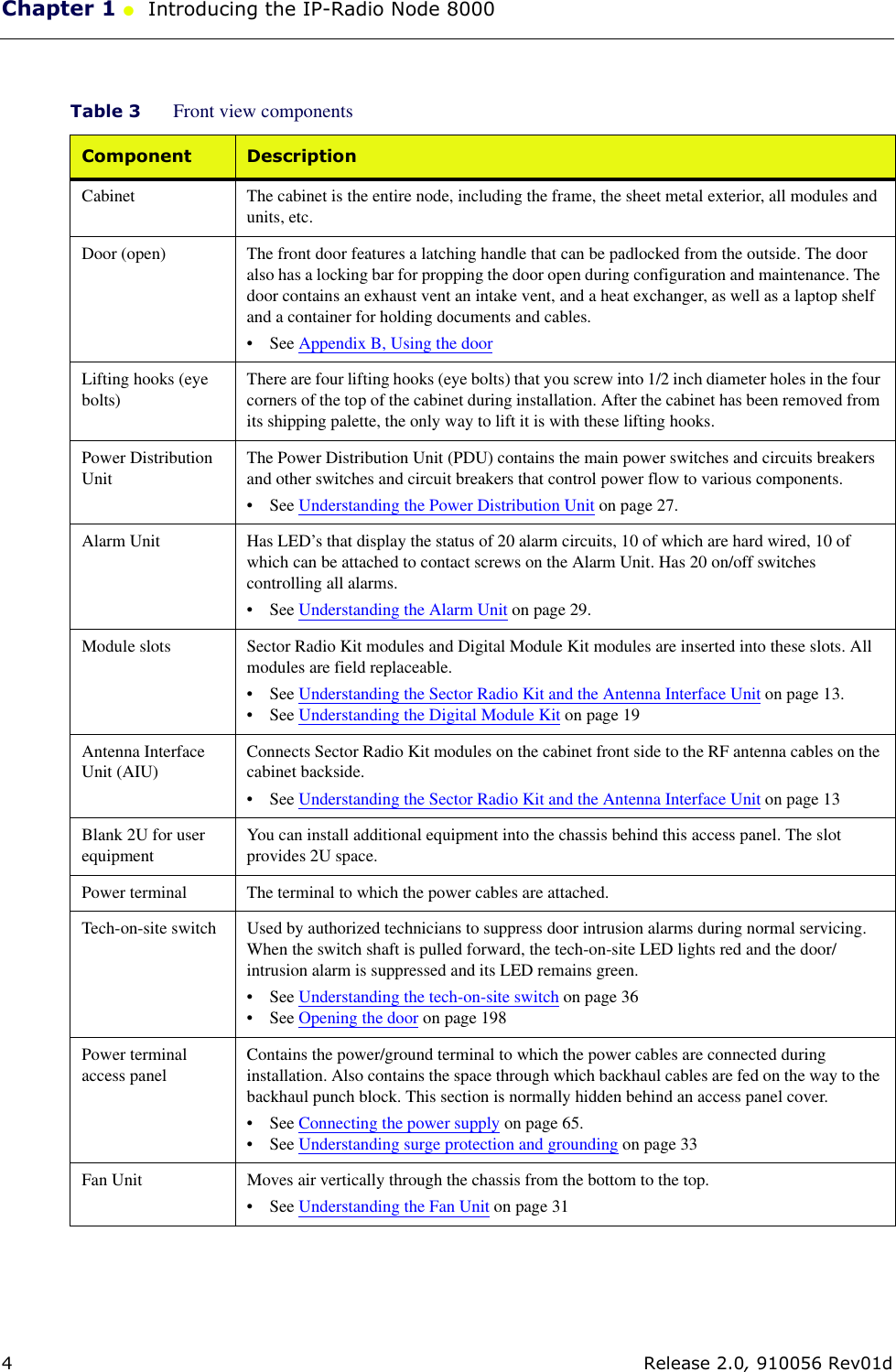
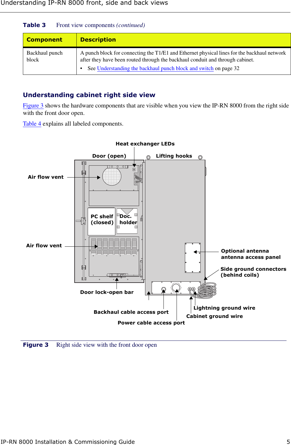
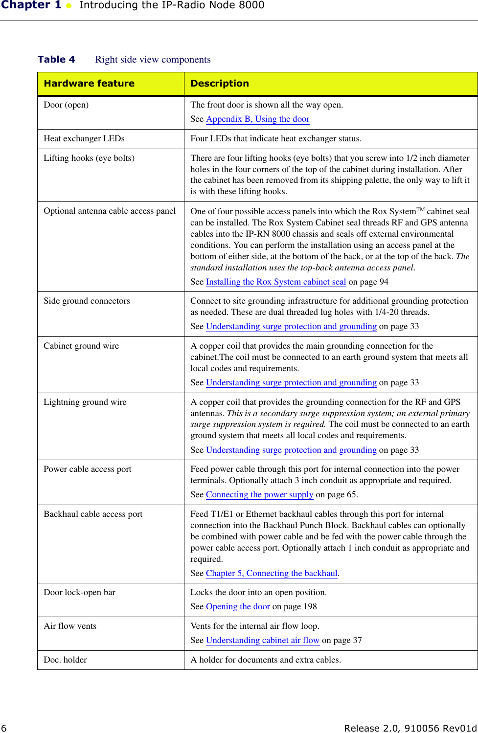
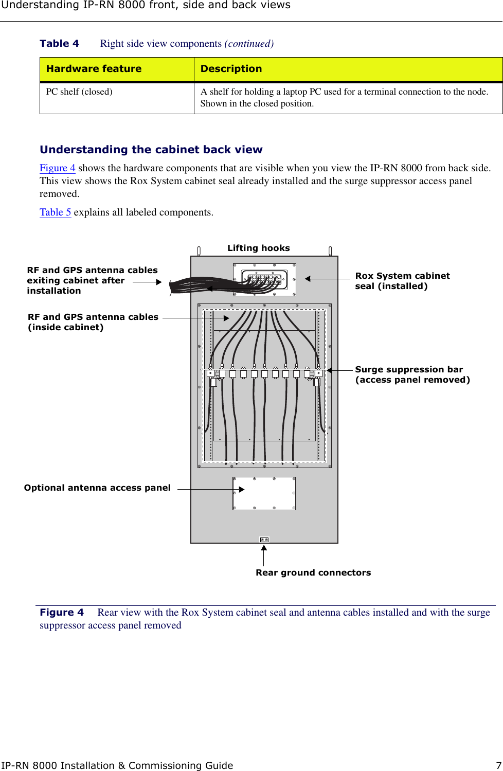
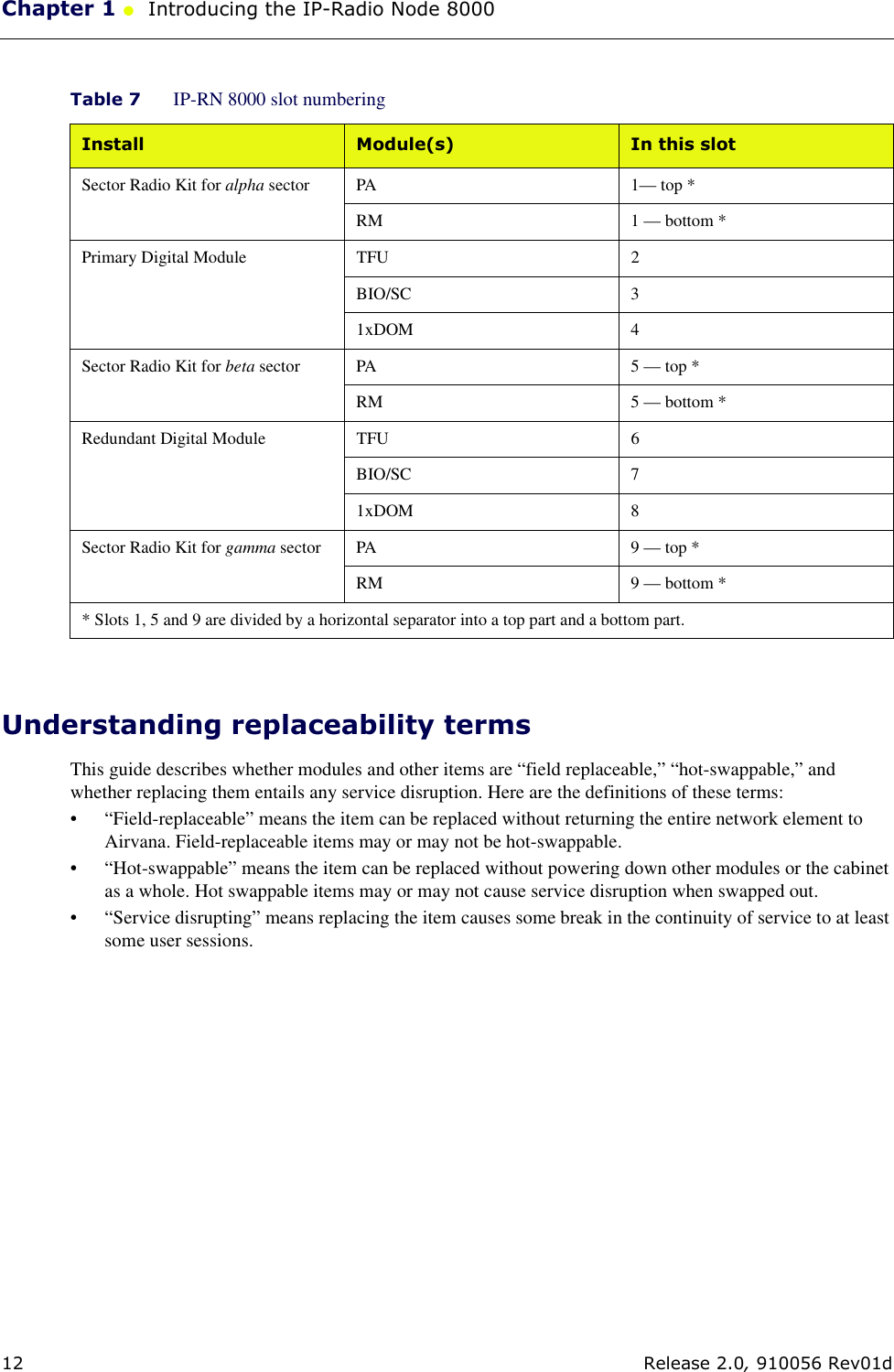
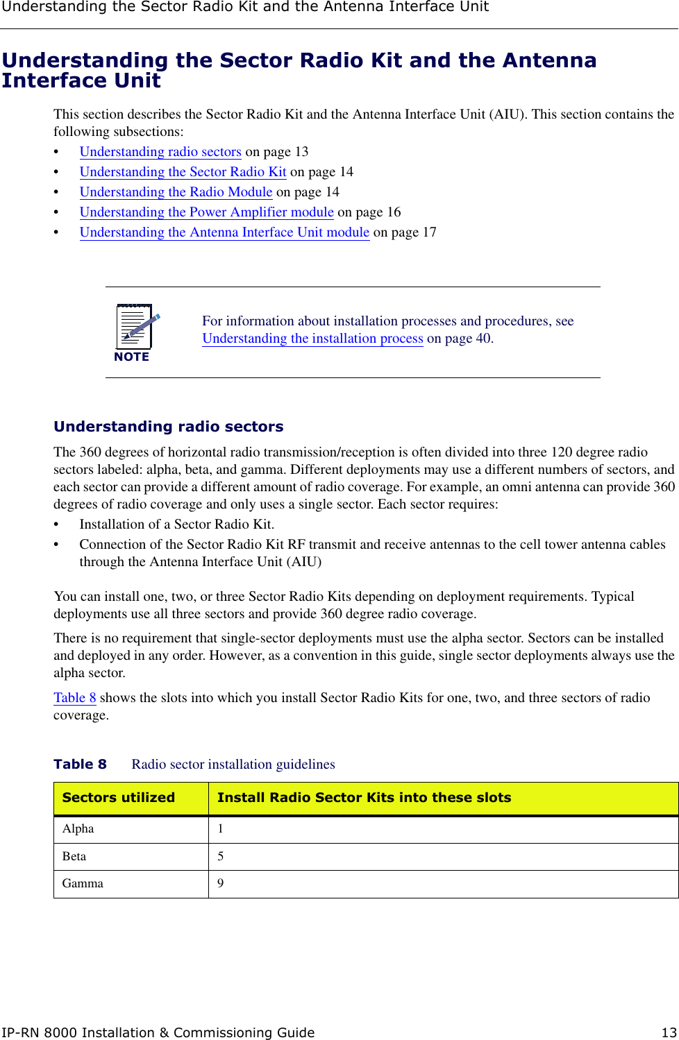
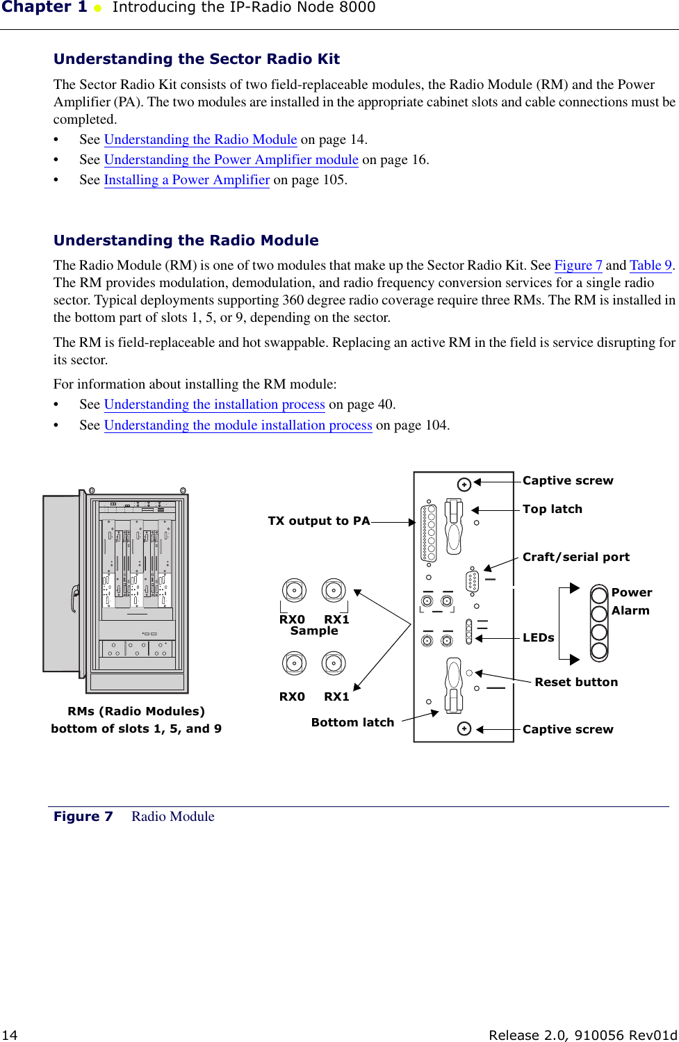
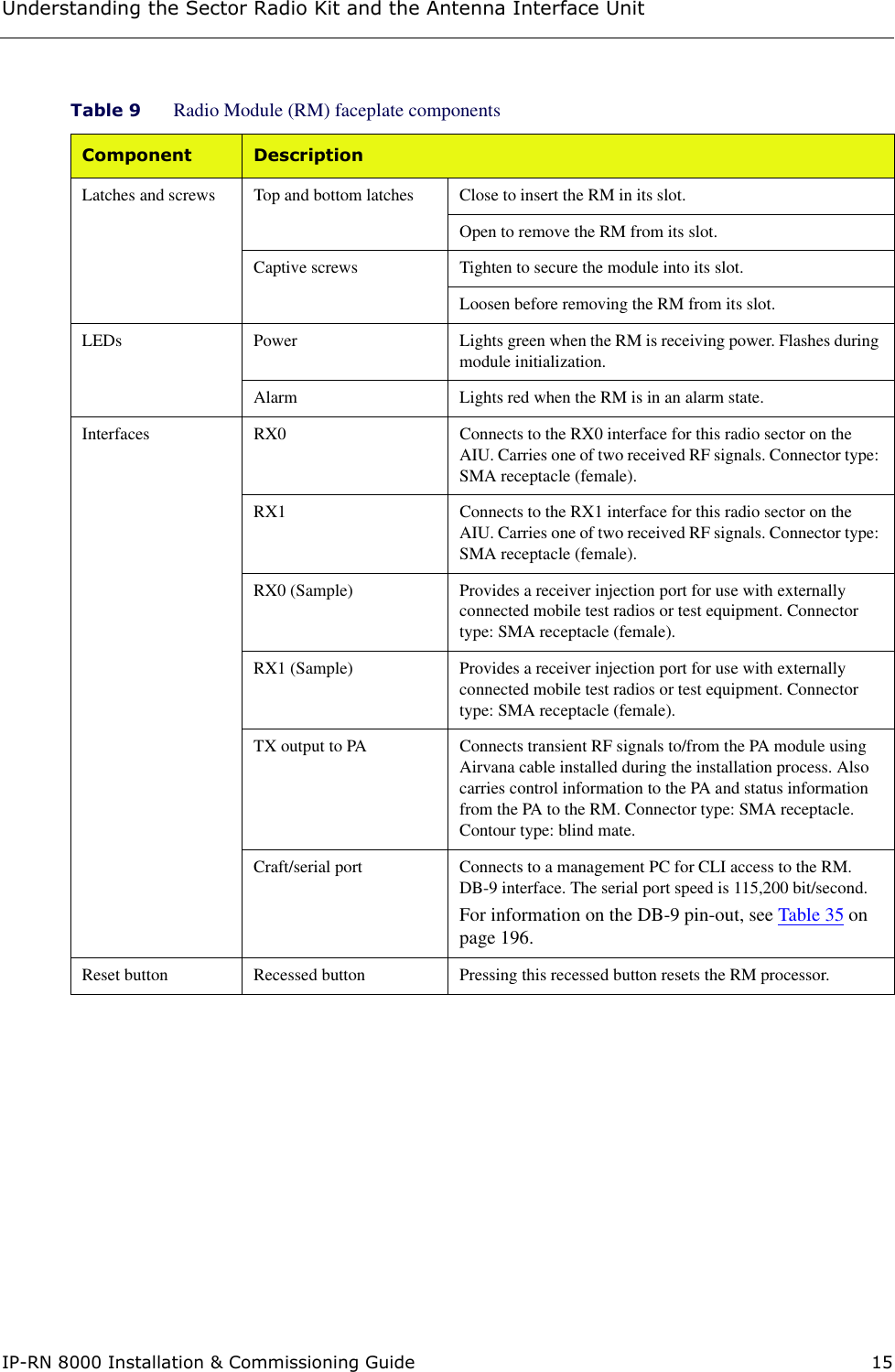
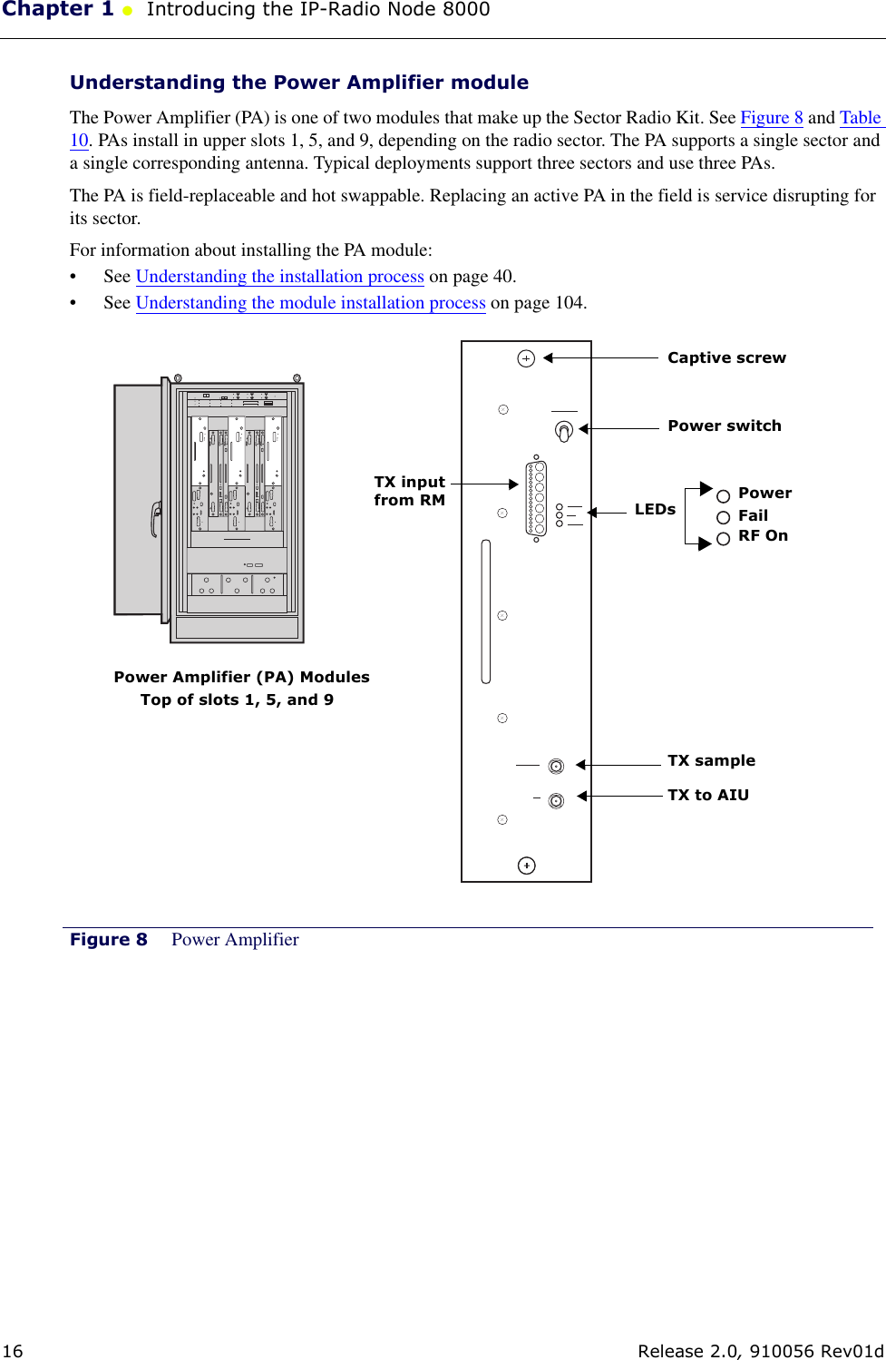
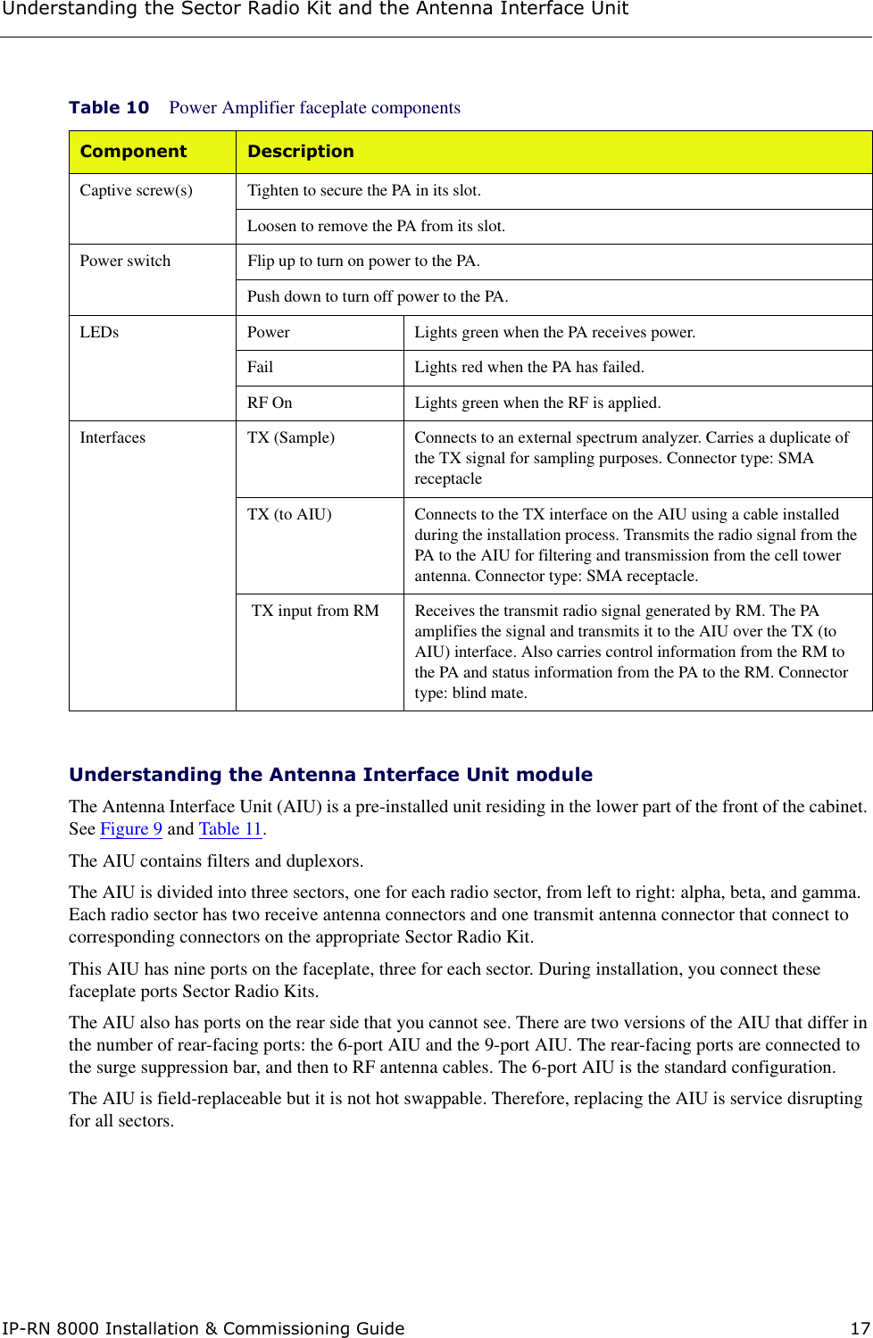
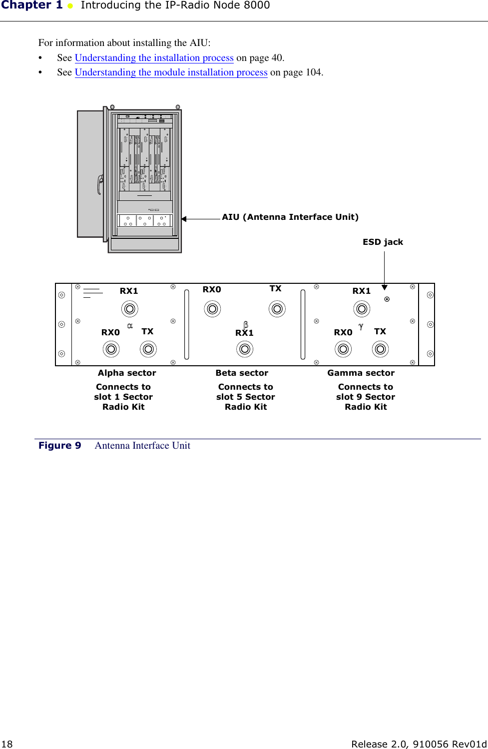
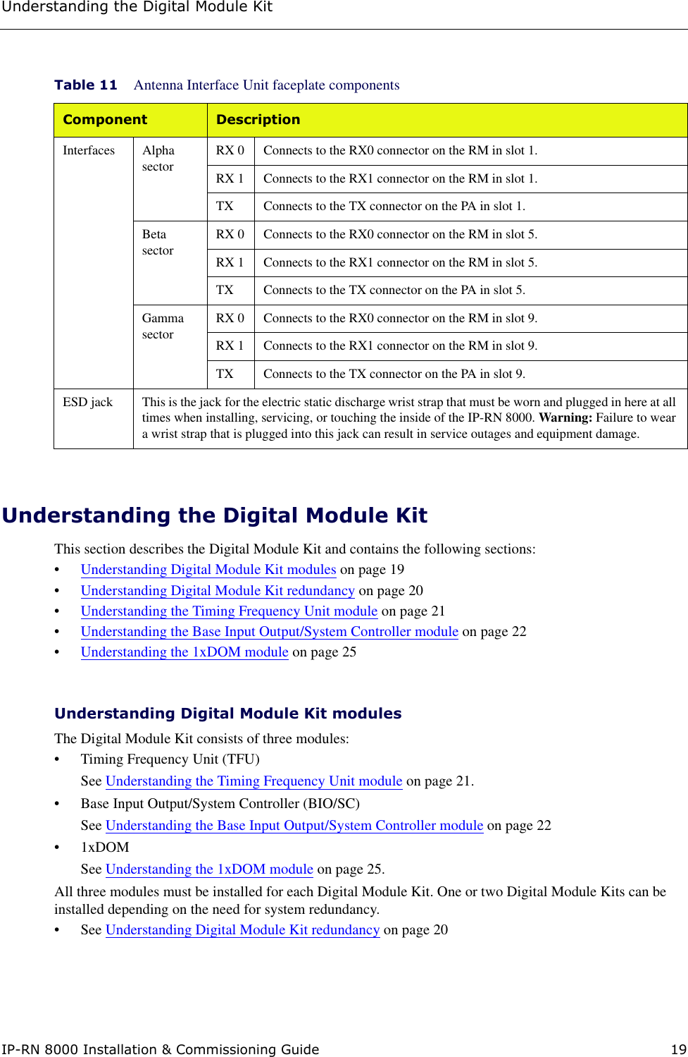
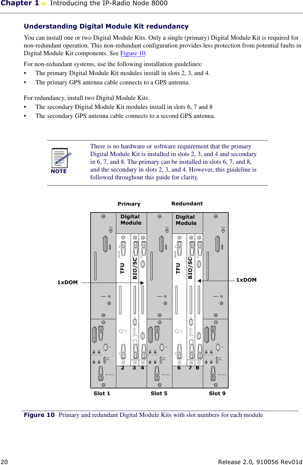
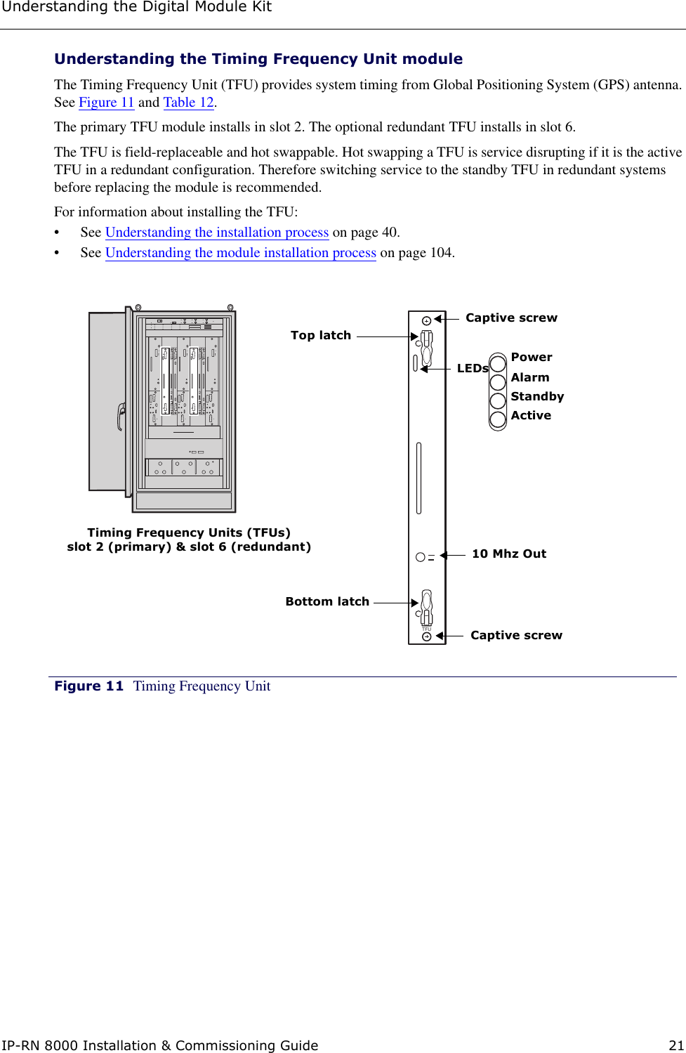
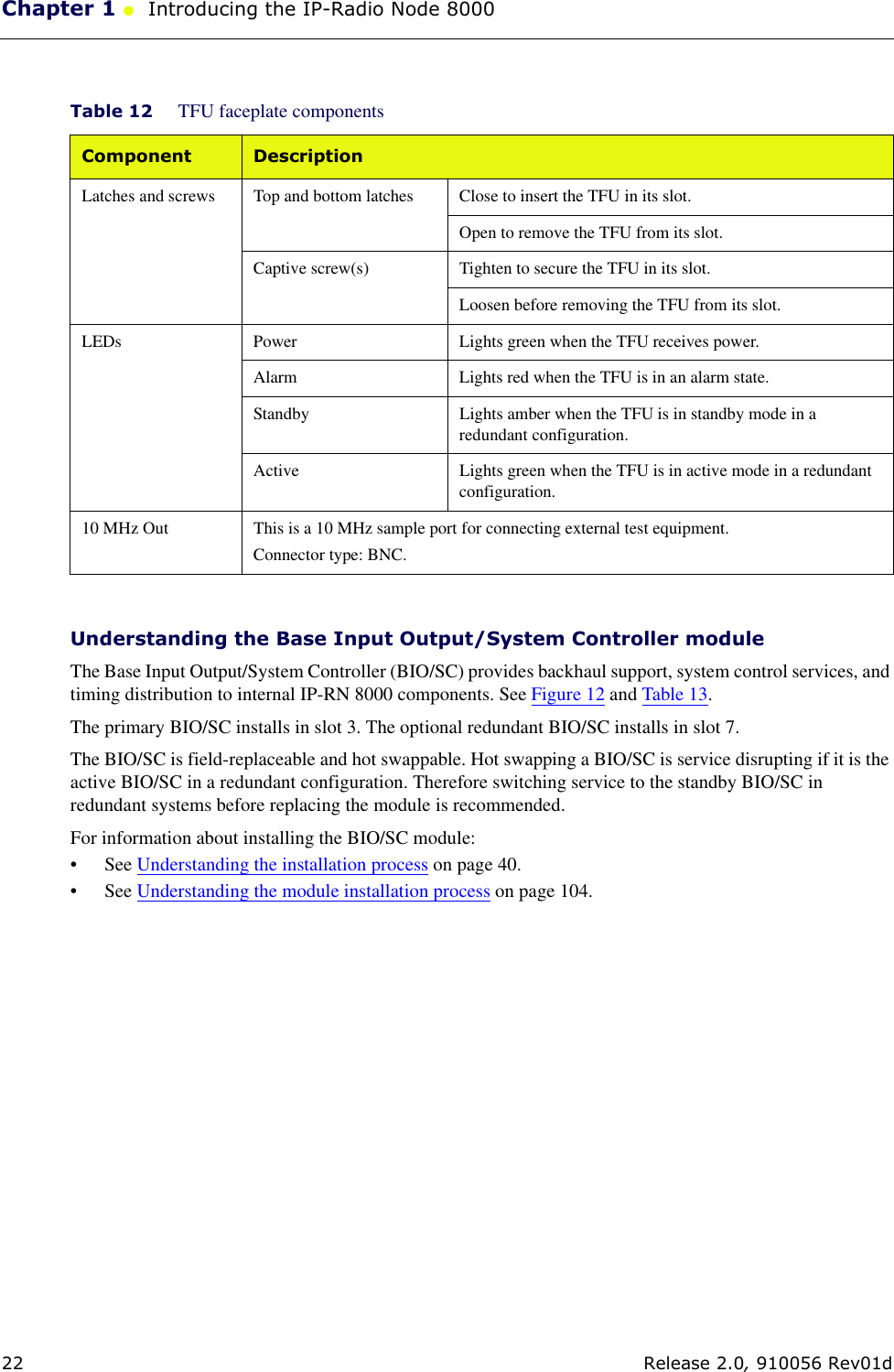
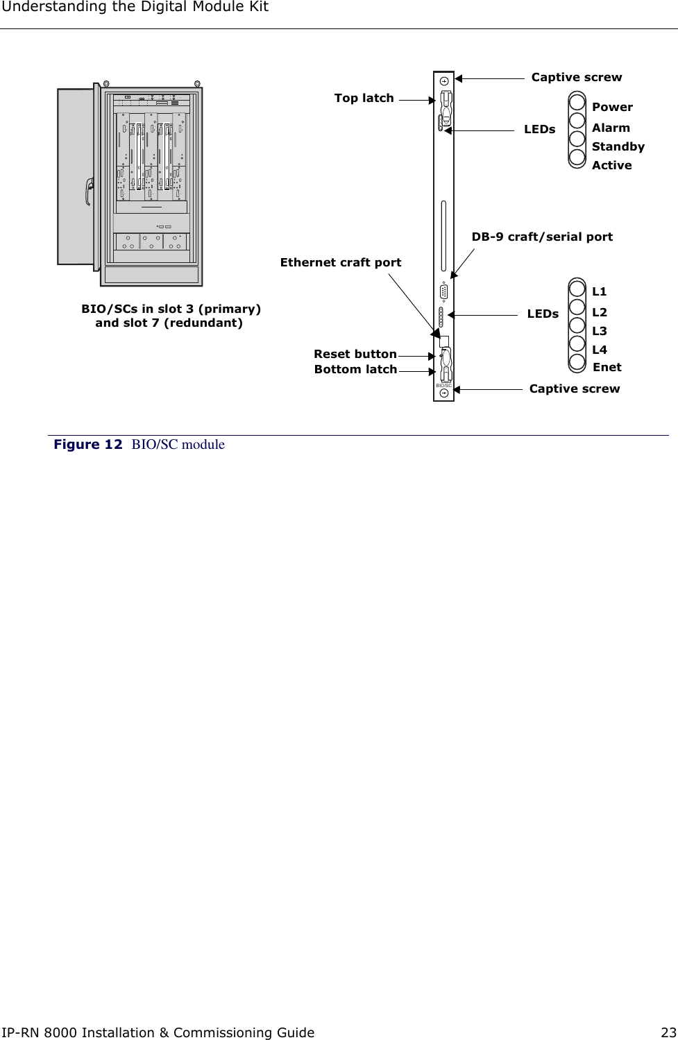
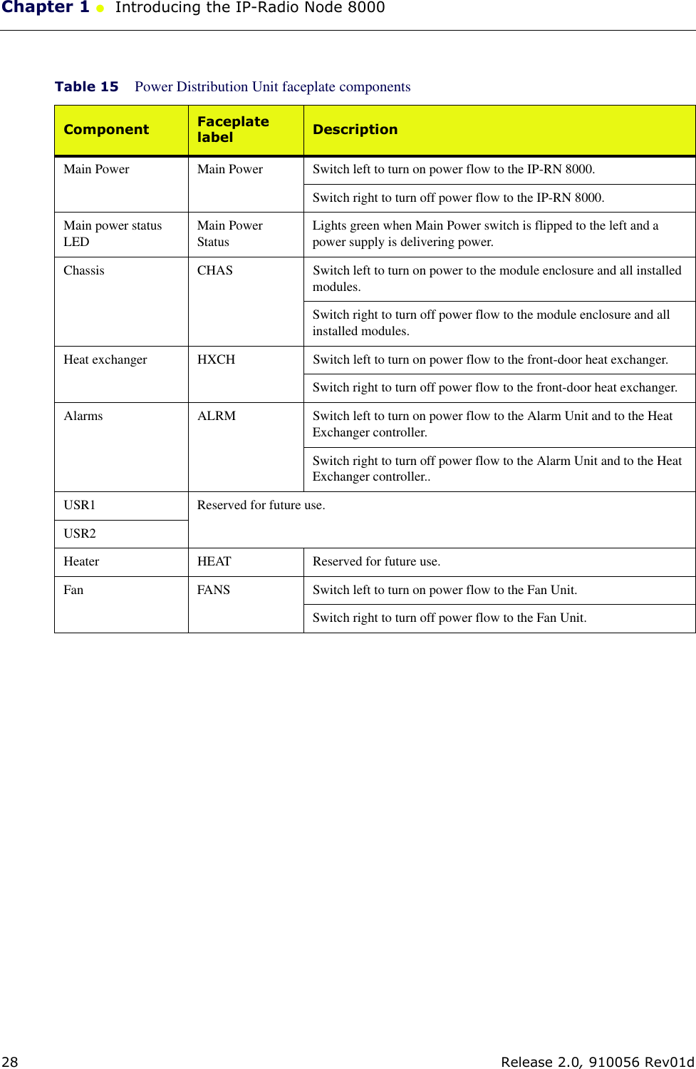
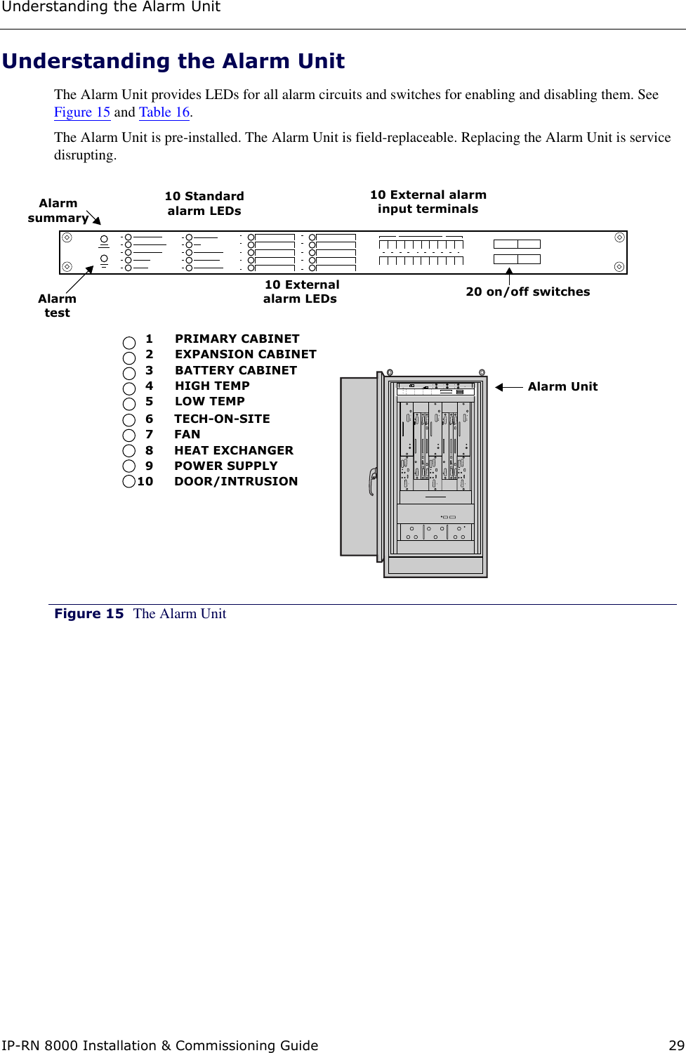
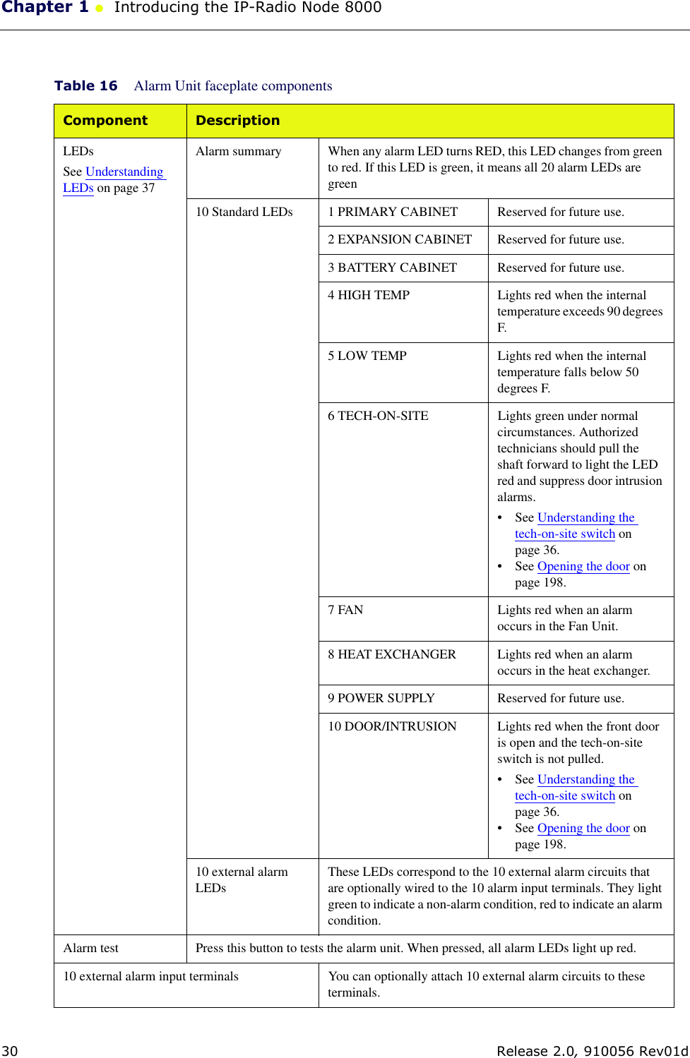
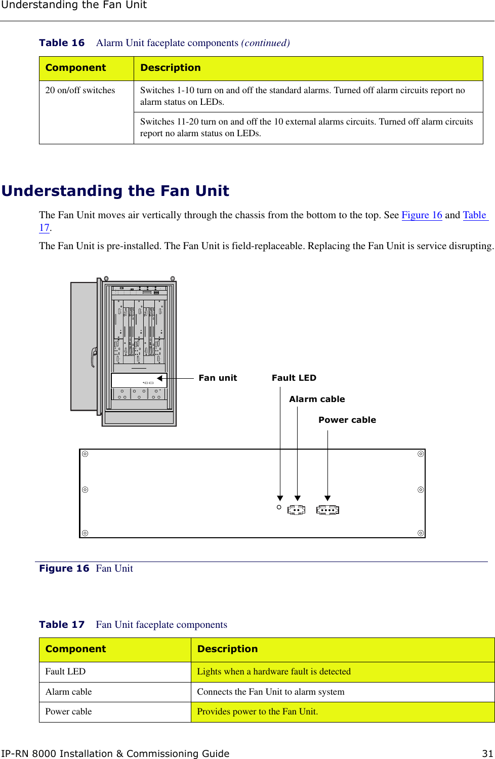
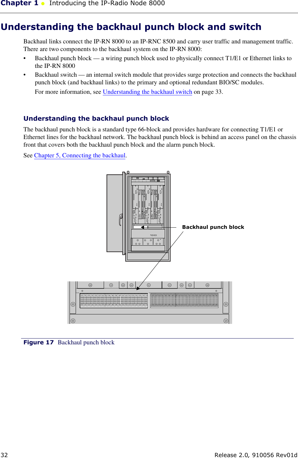
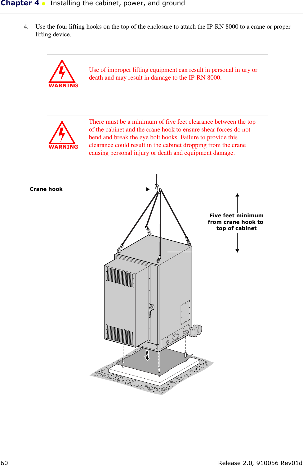
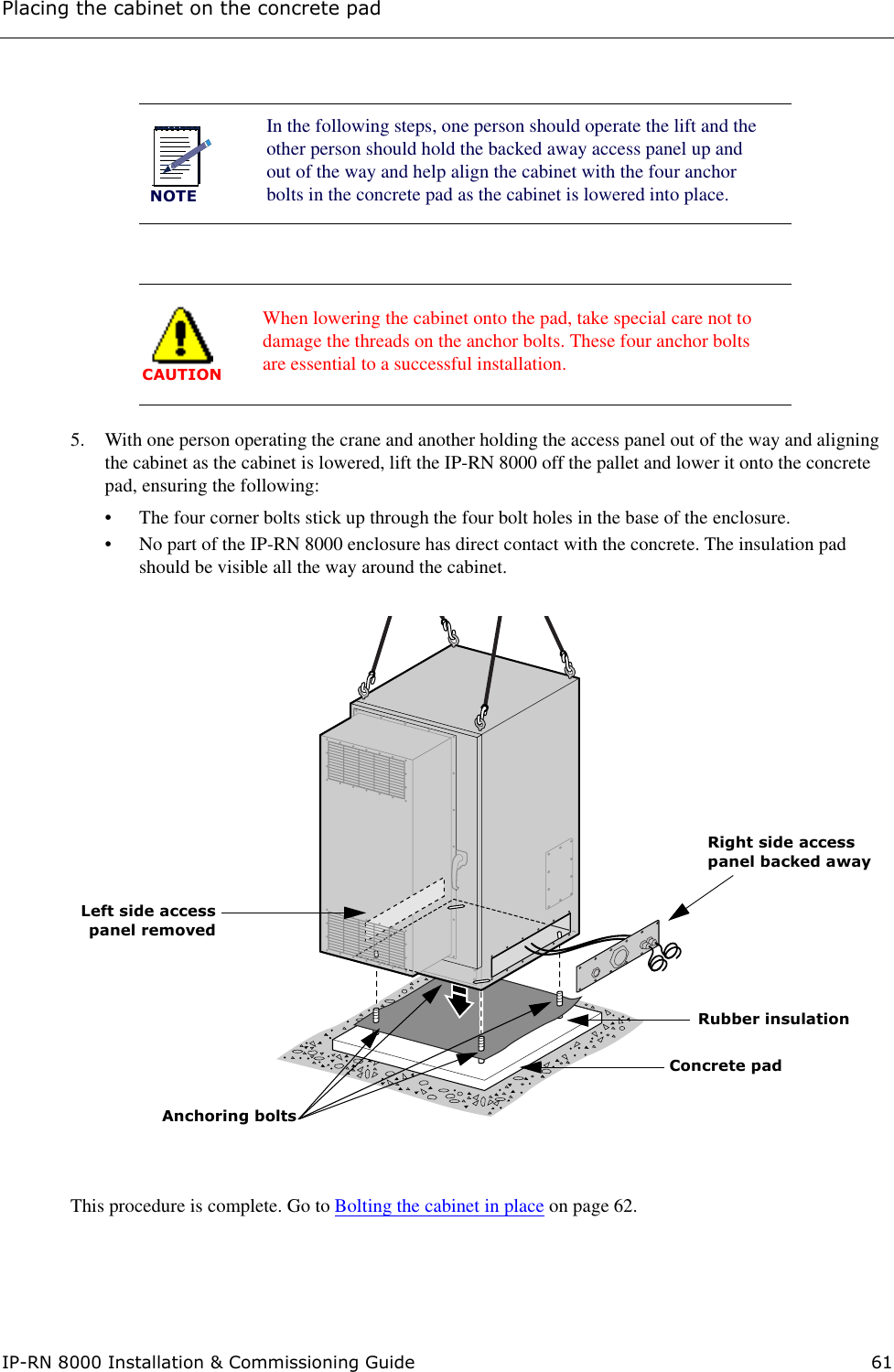
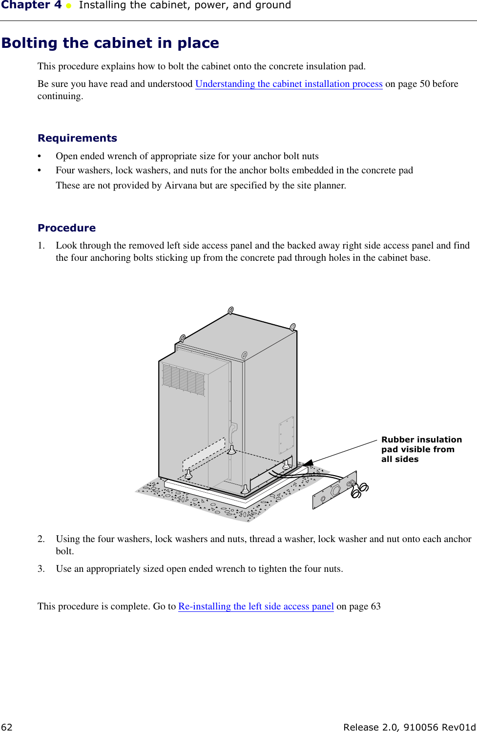
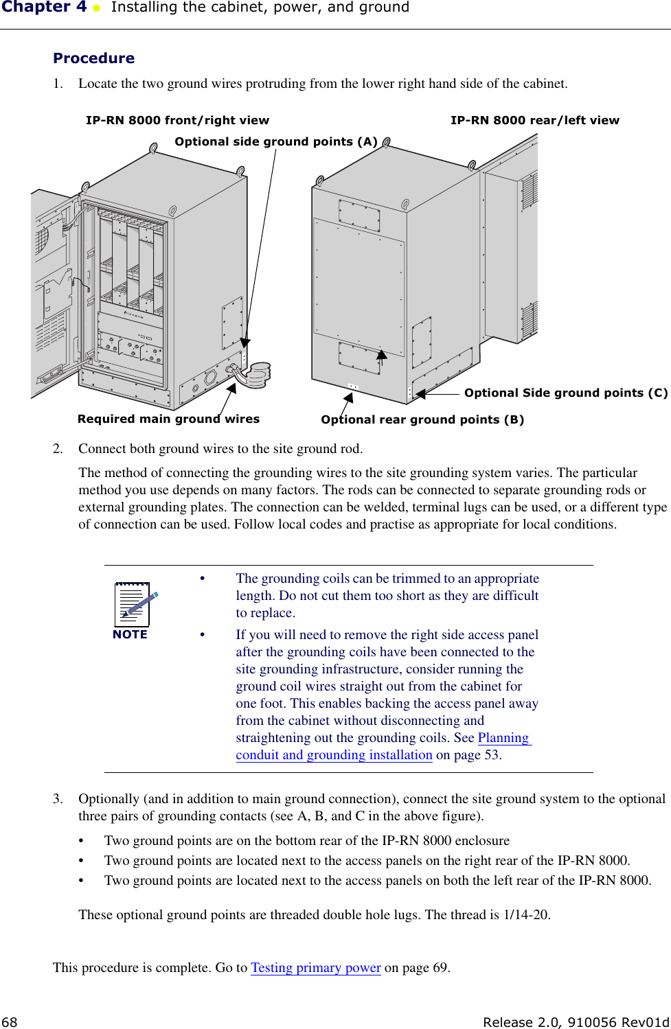
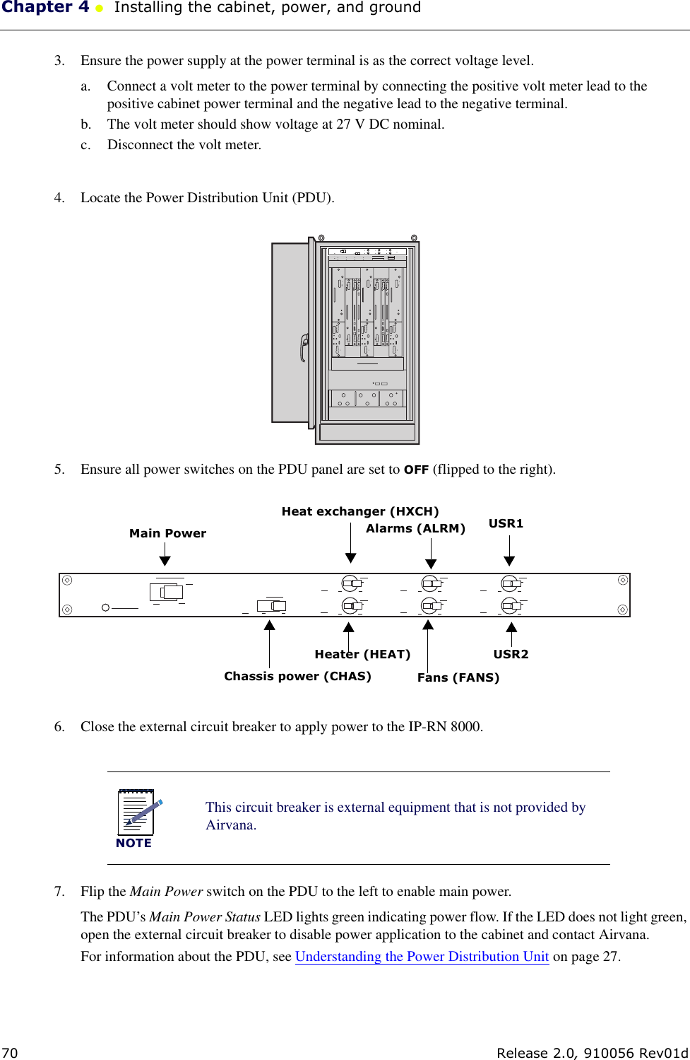
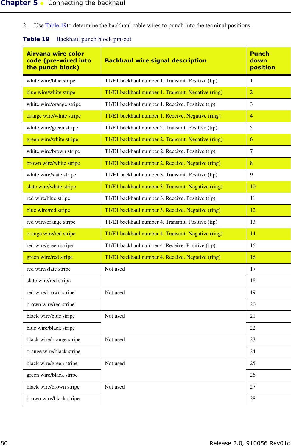
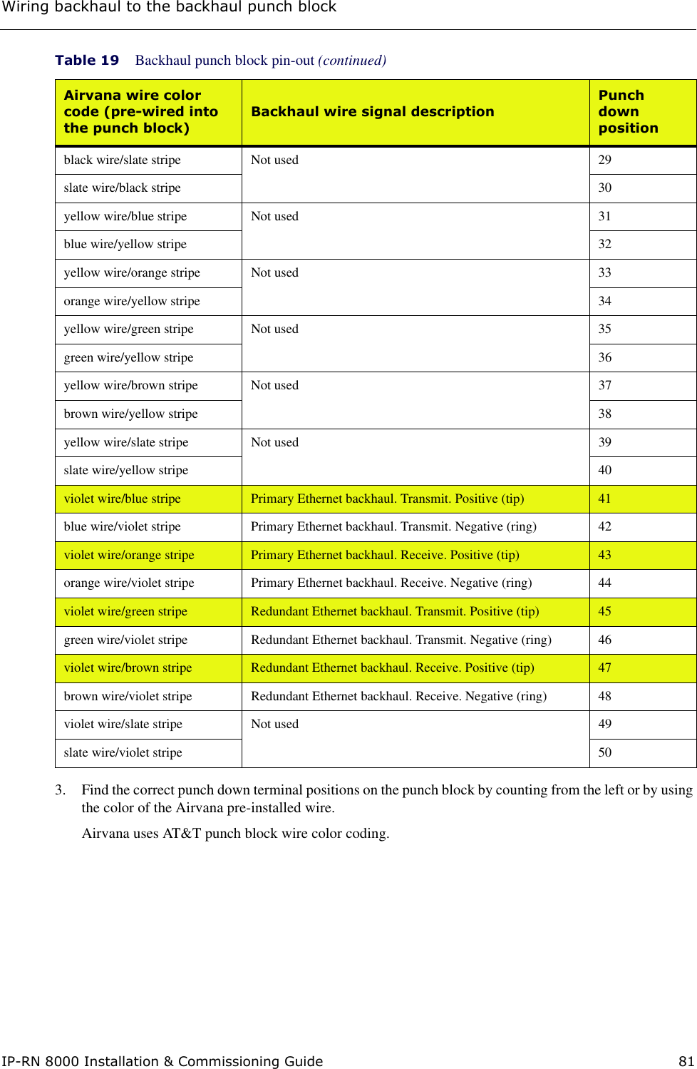
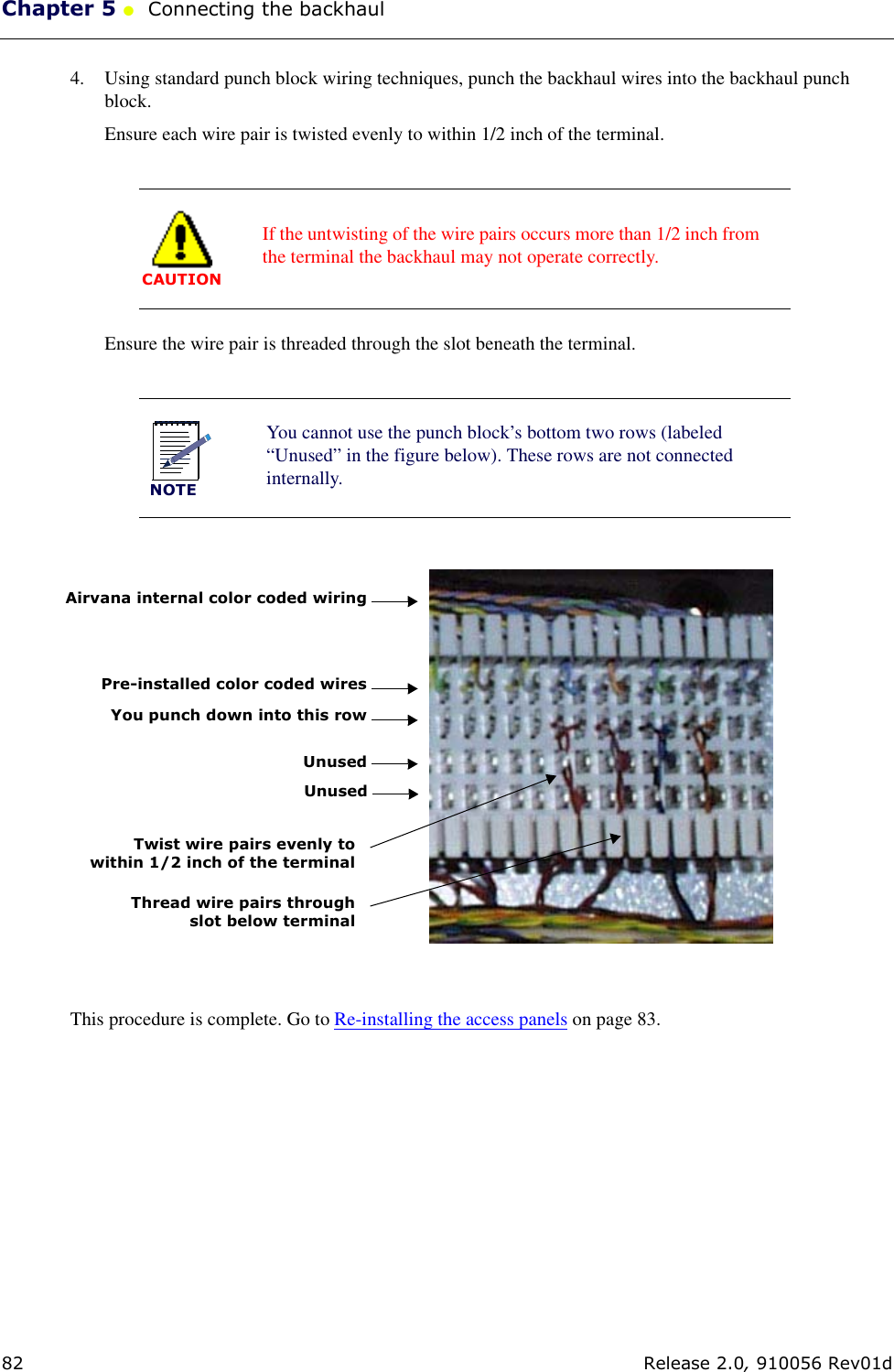
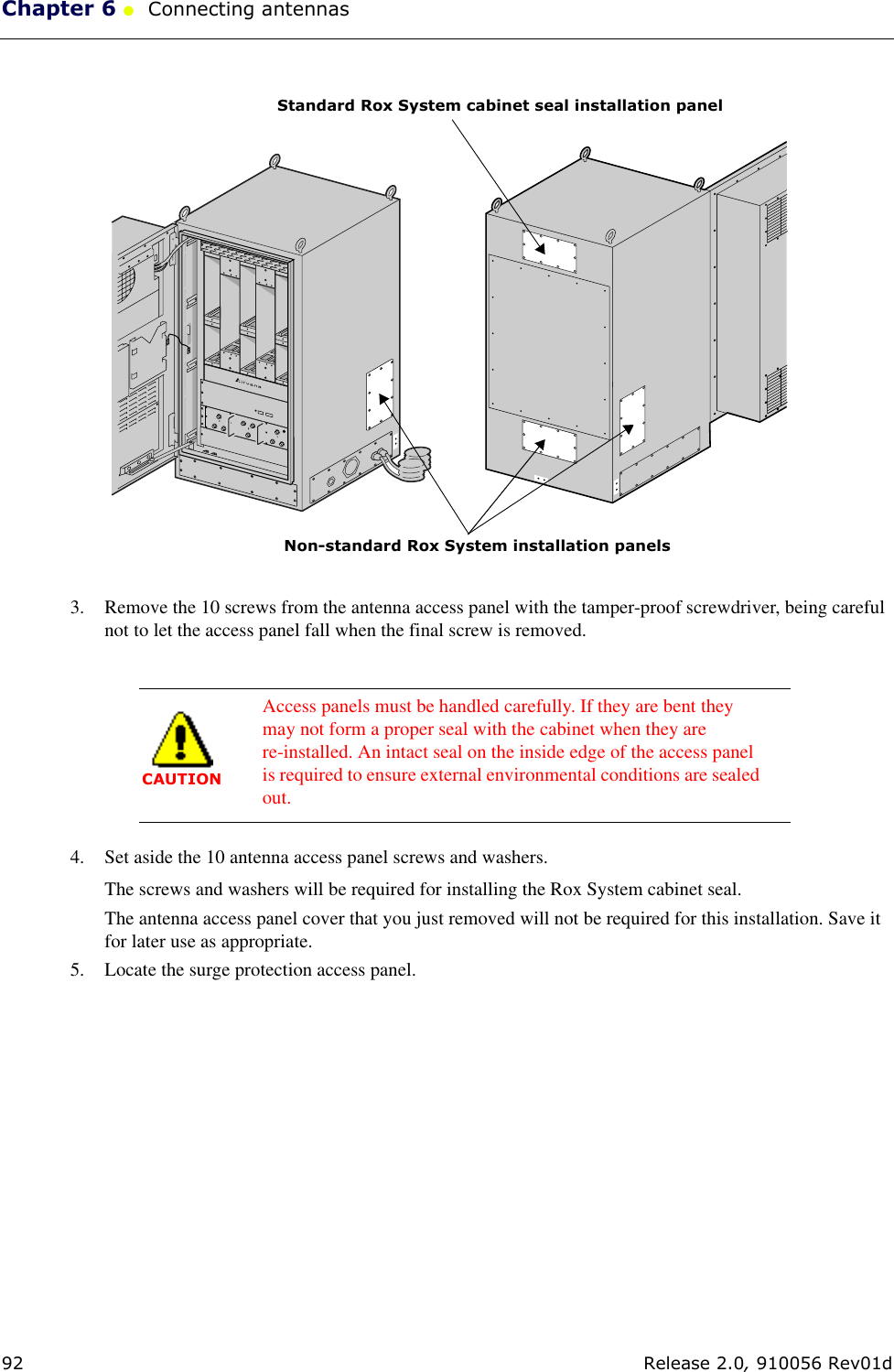
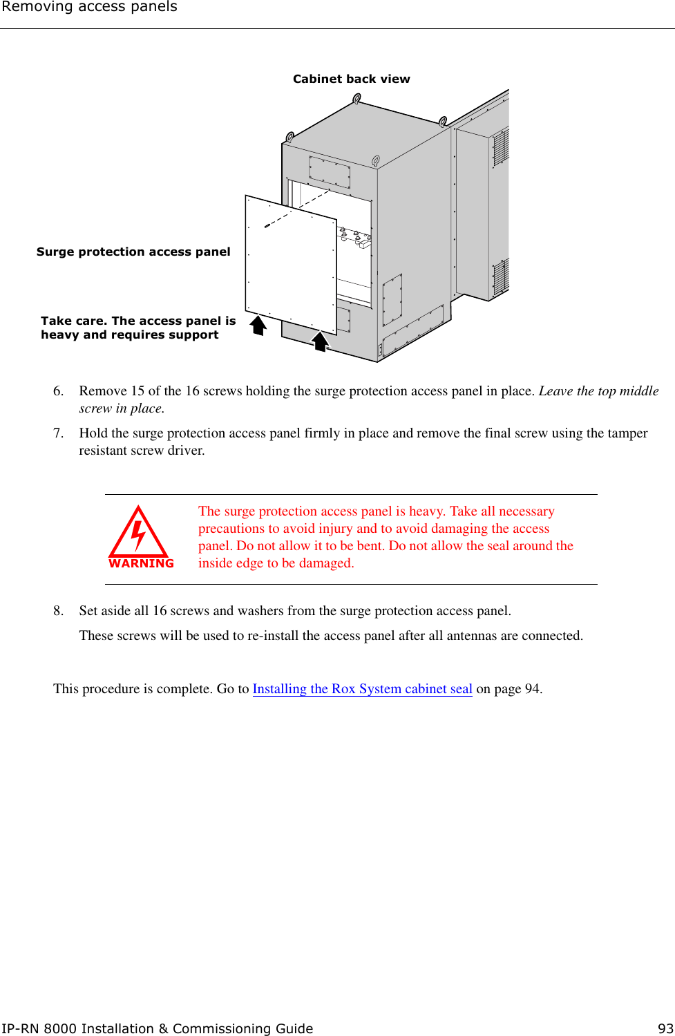
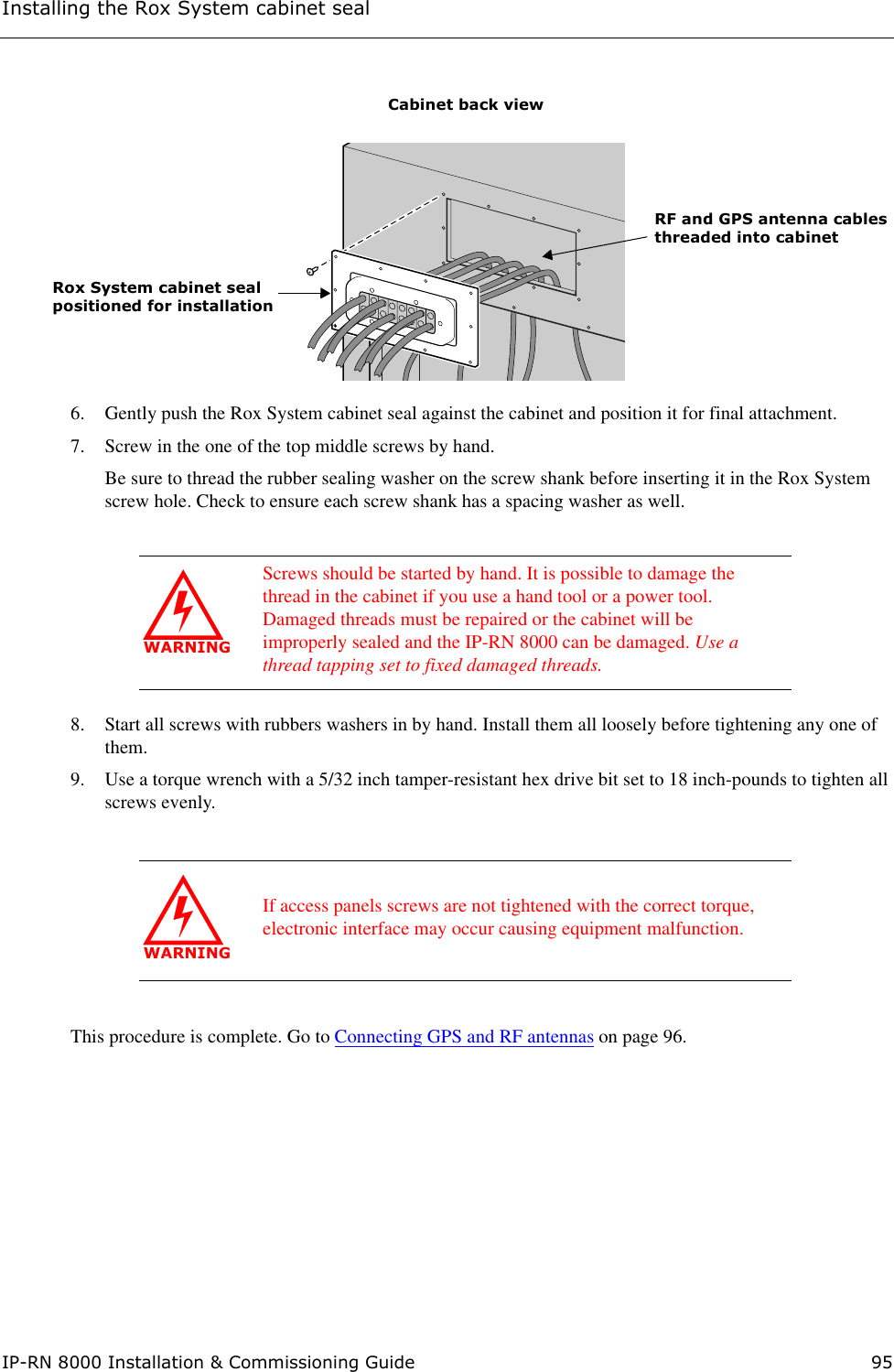
![ConventionsIP-RN 8000 Installation & Commissioning Guide xvConventionsThis section describes Airvana document conventions. It contains these sections:•Text conventions on page xv•Icon conventions on page xvii Text conventionsTable 1 lists and describes the text conventions in Airvana guides.Table 1 Airvana text conventionsConvention Descriptionbold face angle brackets< > Indicate a required parameter in a Command Line Interface (CLI) command. For example:>band-class <class>In the above example, <class> is a required parameter that happens to be a variable parameter (indicated by the italics) with a range of 1 to 3. A valid command in this syntax is:>band-class 3Indicate that you press the keyboard character enclosed in the brackets. For example:• Press <ENTER> to continue.In the above example, you press the Enter key to continue.• Press <CTRL><ALT><DELETE> to reboot your computer. In the above example, you press the Ctrl, Alt, and Delete keys simultaneously to reboot your computer.boldface screen font Indicates text that must be entered exactly as shown. For example:•Enter ping 192.23.10.12 at the CLI prompt.•Enter 255.255.255.0 in the Net Mask field.In both examples above, you must enter the bold text exactly as shown.italic screen font Indicates a variable parameter in a CLI command. For example:>authentication key <aukey>In the above example, <aukey> is a variable parameter that specifies the authentication key for which you must enter a value, containing up to 16 numbers. A valid command in this syntax is:>authentication key 9782503000boldface square brackets[ ]Indicates an optional parameter in a CLI command. For example:>activate image <version> [reboot]In the above example, [reboot] is an optional parameter. A valid command in this syntax is:>activate image rnc8500.2.0.0boldface pipe character|Indicates you enter one or the other of the identified parameter options. For example:>channel-included <yes | no>A valid command in this syntax is:>channel-included yes](https://usermanual.wiki/CommScope-Technologies/800002-1.Manual-1/User-Guide-360236-Page-15.png)