CommScope Technologies 800002-1 Licensed Base Station User Manual IP RN 8000 I C Guide
Airvana, LP Licensed Base Station IP RN 8000 I C Guide
Contents
- 1. Manual 1
- 2. Manual 2
Manual 1

®
Cover
IP-RN 8000 Installation and
Commissioning Guide
Release 2.0
910056 Rev01d

IP-RN 8000 Installation & Commissioning Guide iii
IP-RN 8000 Installation and Commissioning
Guide

iv Release 2.0, 910056 Rev01d
Copyright
2002 and 2003 Airvana, Inc. All rights reserved.
A
irvana is a registered trademark of Airvana. AirVista is a trademark of Airvana. All other trademarks ar
e
t
rademarks of their respective owners.
T
his document contains information that is the property of Airvana, Inc. This document may not be
c
opied, reproduced, reduced to any electronic medium or machine readable form, or otherwise duplicated
,
a
nd the information herein may not be used, disseminated or otherwise disclosed, except with the prior
w
ritten consent of Airvana, Inc.
T
HE SPECIFICATIONS AND INFORMATION REGARDING THE PRODUCTS IN THIS MANUAL
A
RE SUBJECT TO CHANGE WITHOUT NOTICE. ALL STATEMENTS, INFORMATION, AND
R
ECOMMENDATIONS IN THIS MANUAL ARE BELIEVED TO BE ACCURATE BUT ARE
P
RESENTED WITHOUT WARRANTY OF ANY KIND, EXPRESS OR IMPLIED. USERS MUST
T
AKE FULL RESPONSIBILITY FOR THEIR APPLICATION OF ANY PRODUCTS.
T
HE SOFTWARE LICENSE AND LIMITED WARRANTY FOR THE ACCOMPANYING PRODUC
T
A
RE SET FORTH IN THE INFORMATION PACKET THAT SHIPPED WITH THE PRODUCT AND
A
RE INCORPORATED HEREIN BY REFERENCE. IF YOU ARE UNABLE TO LOCATE THE
S
OFTWARE LICENSE OR LIMITED WARRANTY, CONTACT YOUR AIRVANA SALES
R
EPRESENTATIVE FOR A COPY.

IP-RN 8000 Installation & Commissioning Guide v
Contents
About this guide
About this chapter........................................................................................................................................... xiii
Purpose............................................................................................................................................................. xiv
Audience.......................................................................................................................................................... xiv
Conventions...................................................................................................................................................... xv
Text conventions....................................................................................................................................... xv
Icon conventions..................................................................................................................................... xvii
Related documentation ................................................................................................................................. xviii
Release 2.0 document set...................................................................................................................... xviii
Documentation CD-ROM......................................................................................................................... xx
Release 2.0 online documentation ............................................................................................................ xx
Airvana contact information............................................................................................................................. xx
Chapter 1
Introducing the IP-Radio Node 8000
Understanding the network................................................................................................................................. 2
Understanding IP-RN 8000 front, side and back views...................................................................................... 3
Understanding the cabinet font view ......................................................................................................... 3
Understanding cabinet right side view........................................................................................................ 5
Understanding the cabinet back view......................................................................................................... 7
Understanding access panels ...................................................................................................................... 9
Understanding module slot numbering............................................................................................................. 11
Understanding replaceability terms .................................................................................................................. 12
Understanding the Sector Radio Kit and the Antenna Interface Unit............................................................... 13
Understanding radio sectors...................................................................................................................... 13
Understanding the Sector Radio Kit......................................................................................................... 14
Understanding the Radio Module............................................................................................................. 14
Understanding the Power Amplifier module............................................................................................ 16
Understanding the Antenna Interface Unit module .................................................................................. 17
Understanding the Digital Module Kit ............................................................................................................. 19
Understanding Digital Module Kit modules............................................................................................. 19
Understanding Digital Module Kit redundancy........................................................................................ 20
Understanding the Timing Frequency Unit module ................................................................................. 21
Understanding the Base Input Output/System Controller module ........................................................... 22
Understanding the 1xDOM module.......................................................................................................... 25
Understanding the Power Distribution Unit ..................................................................................................... 27
Understanding the Alarm Unit.......................................................................................................................... 29
Understanding the Fan Unit.............................................................................................................................. 31
Understanding the backhaul punch block and switch....................................................................................... 32
Understanding the backhaul punch block................................................................................................. 32
Understanding the backhaul switch.......................................................................................................... 33
Understanding surge protection and grounding................................................................................................ 33
Understanding the secondary surge protection system............................................................................. 33
Understanding grounding requirements.................................................................................................... 34
Understanding external connections................................................................................................................. 34
Understanding the tech-on-site switch.............................................................................................................. 36
Understanding LEDs......................................................................................................................................... 37
Understanding cabinet air flow......................................................................................................................... 37
Chapter 2
Installation process
About this chapter............................................................................................................................................. 39
Understanding installation and commissioning................................................................................................ 40
Understanding the installation process............................................................................................................. 40
Understanding alternative installation.............................................................................................................. 41

Contents
vi Release 2.0, 910056 Rev01d
Chapter 3
Before you install
About this chapter............................................................................................................................................. 43
Site planning and construction.......................................................................................................................... 44
Planning the network ........................................................................................................................................ 44
Receiving all shipping and materials................................................................................................................ 44
Electro static discharge and GR-1089 compliance........................................................................................... 44
Safety Recommendations and Warnings.......................................................................................................... 45
Radio frequency radiation exposure limits ............................................................................................... 45
Lithium battery warning ........................................................................................................................... 45
Maintaining Safety With Electricity......................................................................................................... 45
Warning Definition................................................................................................................................... 46
Product Disposal....................................................................................................................................... 46
Lightning Activity Warning...................................................................................................................... 46
Jewelry Removal Warning........................................................................................................................ 46
Power Supply Warning............................................................................................................................. 46
Power Supply Disconnection Warning..................................................................................................... 46
Power Disconnection Warning................................................................................................................. 46
Grounded Equipment Warning................................................................................................................. 47
Installation Warning ................................................................................................................................. 47
Notices .............................................................................................................................................................. 47
Part-68 Notice........................................................................................................................................... 47
Chapter 4
Installing the cabinet, power, and ground
About this chapter............................................................................................................................................. 49
Understanding the cabinet installation process................................................................................................. 50
Understanding outdoor installation................................................................................................................... 51
Mounting pad............................................................................................................................................ 51
Loading..................................................................................................................................................... 51
Lifting - overhead space ........................................................................................................................... 51
Earthquakes............................................................................................................................................... 51
Mounting hardware................................................................................................................................... 51
Understanding indoor installation..................................................................................................................... 52
Loading..................................................................................................................................................... 52
Lifting - overhead space ........................................................................................................................... 52
Earthquakes............................................................................................................................................... 52
Mounting................................................................................................................................................... 52
Planning conduit and grounding installation .................................................................................................... 53
Unpacking the cabinet from its shipping container .......................................................................................... 54
Requirements ............................................................................................................................................ 54
Procedure .................................................................................................................................................. 54
Removing access panels ................................................................................................................................... 56
Requirements ............................................................................................................................................ 56
Procedure .................................................................................................................................................. 56
Unbolting the cabinet from its palette............................................................................................................... 57
Requirements ............................................................................................................................................ 57
Procedure .................................................................................................................................................. 57
Placing the cabinet on the concrete pad............................................................................................................ 58
Requirements ............................................................................................................................................ 58
Procedure .................................................................................................................................................. 59
Bolting the cabinet in place .............................................................................................................................. 62
Requirements ............................................................................................................................................ 62
Procedure .................................................................................................................................................. 62
Re-installing the left side access panel ............................................................................................................. 63
Requirements ............................................................................................................................................ 63
Procedure .................................................................................................................................................. 63
Routing power and backhaul cables into cabinet and closing right side access panel ..................................... 64

Contents
IP-RN 8000 Installation & Commissioning Guide vii
Requirements ............................................................................................................................................ 64
Procedure .................................................................................................................................................. 64
Connecting the power supply ........................................................................................................................... 65
Requirements ............................................................................................................................................ 65
Procedure .................................................................................................................................................. 66
Grounding the cabinet....................................................................................................................................... 67
Requirements ............................................................................................................................................ 67
Procedure .................................................................................................................................................. 68
Testing primary power...................................................................................................................................... 69
Requirements ............................................................................................................................................ 69
Procedure .................................................................................................................................................. 69
Chapter 5
Connecting the backhaul
About this chapter............................................................................................................................................. 73
Understanding the backhaul installation process.............................................................................................. 74
Understanding backhaul links........................................................................................................................... 75
Removing the punch block access panel .......................................................................................................... 76
Requirements ............................................................................................................................................ 76
Procedure .................................................................................................................................................. 76
Routing backhaul to the backhaul punch block................................................................................................ 77
Requirements ............................................................................................................................................ 77
Procedure .................................................................................................................................................. 77
Wiring backhaul to the backhaul punch block.................................................................................................. 79
Requirements ............................................................................................................................................ 79
Procedure .................................................................................................................................................. 79
Re-installing the access panels ......................................................................................................................... 83
Requirements ............................................................................................................................................ 83
Procedure .................................................................................................................................................. 83
Chapter 6
Connecting antennas
About this chapter............................................................................................................................................. 85
Understanding the antenna installation process................................................................................................ 86
Understanding warnings and cautions.............................................................................................................. 87
Understanding the pre-assembled Rox System ................................................................................................ 87
Optionally assembling your own Rox .............................................................................................................. 89
Airvana Rox kits....................................................................................................................................... 89
Assembly requirements............................................................................................................................. 89
RF and GPS cable locations...................................................................................................................... 90
Removing access panels ................................................................................................................................... 91
Requirements ............................................................................................................................................ 91
Procedure .................................................................................................................................................. 91
Installing the Rox System cabinet seal ............................................................................................................. 94
Requirements ............................................................................................................................................ 94
Procedure .................................................................................................................................................. 94
Connecting GPS and RF antennas.................................................................................................................... 96
Requirements ............................................................................................................................................ 96
Procedure .................................................................................................................................................. 96
Chapter 7
Installing modules
About this chapter........................................................................................................................................... 103
Understanding the module installation process .............................................................................................. 104
Installing a Power Amplifier........................................................................................................................... 105
Requirements .......................................................................................................................................... 105

Contents
viii Release 2.0, 910056 Rev01d
Procedure ................................................................................................................................................ 106
Installing a Radio Module............................................................................................................................... 108
Requirements .......................................................................................................................................... 108
Procedure ................................................................................................................................................ 108
Connecting the RM to the PA with the RF cable ........................................................................................... 111
Requirements .......................................................................................................................................... 111
Procedure ................................................................................................................................................ 111
Connecting the Sector Radio Kit to the Antenna Interface Unit .................................................................... 113
Requirements .......................................................................................................................................... 113
Procedure ................................................................................................................................................ 113
Installing a Timing Frequency Unit................................................................................................................ 116
Requirements .......................................................................................................................................... 116
Procedure ................................................................................................................................................ 116
Installing a Base Input Output/System Controller.......................................................................................... 119
Requirements .......................................................................................................................................... 119
Procedure ................................................................................................................................................ 119
Installing a 1xDOM ........................................................................................................................................ 122
Requirements .......................................................................................................................................... 122
Procedure ................................................................................................................................................ 122
Chapter 8
Applying primary power
About this chapter........................................................................................................................................... 125
Powering the node .......................................................................................................................................... 126
Requirements .......................................................................................................................................... 126
Procedure ................................................................................................................................................ 126
Chapter 9
Commissioning process
About this chapter........................................................................................................................................... 127
Understanding the commissioning process..................................................................................................... 128
Understanding commissioning requirements.................................................................................................. 129
Requirements .......................................................................................................................................... 129
Other requirements ................................................................................................................................. 129
Software update requirements ................................................................................................................ 129
Chapter 10
Establishing CLI connections
About this chapter........................................................................................................................................... 131
Understanding the CLI connection process.................................................................................................... 132
Understanding CLI/serial connections............................................................................................................ 132
CLI/serial ................................................................................................................................................ 132
CLI/serial on redundant systems..................................................................................................... 132
CLI/telnet/craft Ethernet......................................................................................................................... 133
CLI/telnet/backhaul ................................................................................................................................ 133
Understanding craft Ethernet connection to the node..................................................................................... 133
Establishing the CLI/serial connection........................................................................................................... 135
Requirements .......................................................................................................................................... 135
Procedure ................................................................................................................................................ 135
Configuring IP on the craft Ethernet and laptop............................................................................................. 137
Establishing the CLI/telnet/Ethernet connection............................................................................................ 138
Requirements .......................................................................................................................................... 138
Procedure ................................................................................................................................................ 138

Contents
IP-RN 8000 Installation & Commissioning Guide ix
Chapter 11
Updating node software
About this chapter........................................................................................................................................... 139
Understanding the software update process.................................................................................................... 140
Checking the active release and free disk space............................................................................................. 140
Requirements .......................................................................................................................................... 140
Procedure ................................................................................................................................................ 141
Transferring the node software from the laptop to the node........................................................................... 142
Requirements .......................................................................................................................................... 142
Procedure ................................................................................................................................................ 142
Activating the release...................................................................................................................................... 144
Chapter 12
Running the commissioning script
About this chapter........................................................................................................................................... 145
Understanding the scripting process............................................................................................................... 146
Understanding scripts ..................................................................................................................................... 146
Understanding script transfer options............................................................................................................. 147
Serial link requires less configuration .................................................................................................... 147
Remote file transfer requires FTP........................................................................................................... 147
Use FTP to transfer large files such as software releases....................................................................... 147
Initializing the node to receive a file with kermit........................................................................................... 147
Transmitting a script from a laptop to the network element........................................................................... 148
Verifying the script file is on the node ........................................................................................................... 154
Running the script........................................................................................................................................... 155
Chapter 13
Loopback testing backhaul links
About this chapter........................................................................................................................................... 157
Understanding the backhaul link loopback test process................................................................................. 158
Understanding backhaul loopback testing...................................................................................................... 159
Understanding a typical T1/E1 backhaul network.......................................................................................... 160
Understanding Ethernet loopbacks................................................................................................................. 160
Looping back T1/E1 backhaul links............................................................................................................... 161
Looping back Ethernet backhaul links............................................................................................................ 162
Entering diagnostic mode and configuring test parameters............................................................................ 163
Requirements .......................................................................................................................................... 163
Procedure ................................................................................................................................................ 163
Performing external loopback tests on backhaul links ................................................................................... 164
Troubleshooting failed backhaul links............................................................................................................ 166
Removing physical loopbacks ........................................................................................................................ 168
Chapter 14
Calibrating transmit power
About this chapter........................................................................................................................................... 169
Understanding the transmit power calibration process................................................................................... 170
Understanding calibration purpose................................................................................................................. 171
Understanding requirements........................................................................................................................... 171
Understanding the need for simultaneous CLI sessions................................................................................. 171
Enabling the base station and checking the IP-RNC 8500............................................................................. 172
Requirements .......................................................................................................................................... 172
Procedure ................................................................................................................................................ 172
Verifying GPS status ...................................................................................................................................... 172
Requirements .......................................................................................................................................... 172
Procedure ................................................................................................................................................ 173
Disabling all sectors........................................................................................................................................ 174

Contents
xRelease 2.0, 910056 Rev01d
Requirements .......................................................................................................................................... 174
Procedure ................................................................................................................................................ 174
Attaching the sector’s test equipment............................................................................................................. 176
Required tools......................................................................................................................................... 176
Warnings................................................................................................................................................. 176
Procedure ................................................................................................................................................ 177
Enabling and blossoming the sector to be calibrated...................................................................................... 178
Requirements .......................................................................................................................................... 178
Procedure ................................................................................................................................................ 178
Starting FTAP for the sector........................................................................................................................... 179
Requirements .......................................................................................................................................... 179
Procedure ................................................................................................................................................ 179
Measuring power loss for the sector............................................................................................................... 180
Requirements .......................................................................................................................................... 180
Procedure ................................................................................................................................................ 180
Setting the sector’s transmit power................................................................................................................. 181
Requirements .......................................................................................................................................... 181
Procedure ................................................................................................................................................ 181
Verifying the sector’s power level.................................................................................................................. 182
Requirements .......................................................................................................................................... 182
Procedure ................................................................................................................................................ 182
Completing the sector’s transmit power calibration process.......................................................................... 183
Requirements .......................................................................................................................................... 183
Warnings................................................................................................................................................. 183
Procedure ................................................................................................................................................ 184
Blossoming and enabling all sectors............................................................................................................... 185
Requirements .......................................................................................................................................... 185
Procedure ................................................................................................................................................ 185
Chapter 15
Completing commissioning
About this chapter........................................................................................................................................... 187
Understanding the commissioning completion process.................................................................................. 188
Checking the modules with CLI..................................................................................................................... 188
Disconnecting the laptop ................................................................................................................................ 189
Preparing the cabinet for your departure ........................................................................................................ 189
Preparing the site for your departure .............................................................................................................. 190
Appendix A
IP-RN 8000 Specifications
About this appendix........................................................................................................................................ 191
Appendix B
Using the door
About this appendix........................................................................................................................................ 197
Opening the door ............................................................................................................................................ 198
Closing the door.............................................................................................................................................. 199
Padlocking the door ........................................................................................................................................ 200
Opening the PC shelf...................................................................................................................................... 201
Closing the PC shelf ....................................................................................................................................... 202
Appendix C
Using access panels
About this appendix........................................................................................................................................ 203
Removing the power terminal access panel.................................................................................................... 204
Requirements .......................................................................................................................................... 204
Re-installing the power terminal access panel................................................................................................ 205

Contents
IP-RN 8000 Installation & Commissioning Guide xi
Requirements:......................................................................................................................................... 205
Re-installing the right side cable access panel................................................................................................ 207
Glossary
Acronyms
Index

Contents
xii Release 2.0, 910056 Rev01d

IP-RN 8000 Installation & Commissioning Guide xiii
About this guide
About this chapter
This chapter provides information you need to use the IP-RN 8000 Installation and Commissioning
Guide effectively. Specifically, it contains the following sections:
•Purpose on page xiv
•Audience on page xiv
•Conventions on page xv
•Related documentation on page xviii
•Airvana contact information on page xx

About this guide
xiv Release 2.0, 910056 Rev01d
Purpose
This guide provides detailed processes and procedures required to install and commission an IP-RN 8000.
Audience
This guide should be read by network planners in order to understand the installation and commissioning
process and requirements. This guide should be used by field technicians to install and commission nodes at
cell sites.
Field technicians installing nodes must be able to use the following:
• Common tools such as screwdrivers and wrenches
• Torque wrench
• Thread tapping kits
• Crane for lifting the cabinet onto the concrete pad
• 66-punch blocks
Field technicians commissioning nodes must use a variety of software applications, including:
• Window 98 (at least)
•FTP
• HyperTerminal or an equivalent terminal emulation program.
They must also be able to understand serial connections, CLI node management, telnet, and Ethernet
connections.

Conventions
IP-RN 8000 Installation & Commissioning Guide xv
Conventions
This section describes Airvana document conventions. It contains these sections:
•Text conventions on page xv
•Icon conventions on page xvii
Text conventions
Table 1 lists and describes the text conventions in Airvana guides.
Table 1 Airvana text conventions
Convention Description
bold face angle brackets
< > Indicate a required parameter in a Command Line Interface (CLI) command.
For example:
>band-class <class>
In the above example, <class> is a required parameter that happens to be a
variable parameter (indicated by the italics) with a range of 1 to 3. A valid
command in this syntax is:
>band-class 3
Indicate that you press the keyboard character enclosed in the brackets. For
example:
• Press <ENTER> to continue.
In the above example, you press the Enter key to continue.
• Press <CTRL><ALT><DELETE> to reboot your computer.
In the above example, you press the Ctrl, Alt, and Delete keys
simultaneously to reboot your computer.
boldface screen font Indicates text that must be entered exactly as shown. For example:
•Enter ping 192.23.10.12 at the CLI prompt.
•Enter 255.255.255.0 in the Net Mask field.
In both examples above, you must enter the bold text exactly as shown.
italic screen font Indicates a variable parameter in a CLI command. For example:
>authentication key <aukey>
In the above example, <aukey> is a variable parameter that specifies the
authentication key for which you must enter a value, containing up to 16
numbers. A valid command in this syntax is:
>authentication key 9782503000
boldface square brackets
[ ]
Indicates an optional parameter in a CLI command. For example:
>activate image <version> [reboot]
In the above example, [reboot] is an optional parameter. A valid
command in this syntax is:
>activate image rnc8500.2.0.0
boldface pipe character
|
Indicates you enter one or the other of the identified parameter options. For
example:
>channel-included <yes | no>
A valid command in this syntax is:
>channel-included yes

About this guide
xvi Release 2.0, 910056 Rev01d
A.B.C.D Indicates a standard IP address. For example:
>telnet <A.B.C.D>
A valid command in this syntax is:
>telnet 10.0.0.1
/bit-length-mask Indicates an IP mask in bit-length format. For example:
>ip address <A.B.C.D/bit-length-mask>
A valid command in this syntax is:
>ip address 10.1.1.1/24
AA:BB:CC:DD:EE:FF Indicates a Media Access Control (MAC) hardware address specified as six
pairs of hexadecimal characters separated by colons. For example:
>ip address <A.B.C.D> <AA:BB:CC:DD:EE:FF>
A valid command in this syntax is:
>ip address 10.1.1.1 11:22:33:DD:EE:FF
arrow icon (⇒)Indicates the Graphical User Interface (GUI) menu path. For example:
Select Edit ⇒ Add Network to open the Add Network screen.
In the above example, you select the Add Network option from the Edit
menu to open the Add Network screen.
blue underline text Indicates a hypertext link in a PDF file to the cross-referenced text. For
example:
See Audience on page xiv.
In the above example, clicking on Audience brings you to the appropriate
section and page in a PDF file for the Audience section.
plain screen font Indicates system output in a command line or system-generated file. For
example:
IP address 192.23.10.12 is alive.
The above example shows the system’s response after you successfully ping
the identified IP address.
boldface font Indicates GUI menu options, drop-down lists, and buttons. For example:
1. Select Edit ⇒ Delete Node.
The system prompts you to confirm the request.
2. Click OK.
plain italic font Indicates file and directory names, book titles, and emphasized words.
Table 1 Airvana text conventions (continued)
Convention Description
Conventions
IP-RN 8000 Installation & Commissioning Guide xvii
Icon conventions
Airvana documents use the following icons:
CAUTION
The caution icon appears in procedures, that, if performed
incorrectly, can damage equipment or lose data.
NOTE
The note icon appears in text that provides additional or helpful
information.
TIP The tip icon appears in text that describes procedure shortcuts.
WARNING
The warning icon appears in procedures, that, if performed
incorrectly, can physically harm you. Before you perform the
procedure, you must be aware of electrical circuitry hazards and
be familiar with standard practices for preventing accidents.
WRIST
STRAP
The wrist strap icon appears in procedures that require you to
wear a wrist strap.

About this guide
xviii Release 2.0, 910056 Rev01d
Related documentation
This section describes documentation related to the IP-RN 8000 Installation and Commissioning Guide. It
contains these sections:
•Release 2.0 document set on page xviii
•Documentation CD-ROM on page xx
•Release 2.0 online documentation on page xx
Release 2.0 document set
Table 2 lists and briefly describes each guide in the Airvana Release 2.0 Customer Documentation set.
Table 2 Release 2.0 document set
Guide title Brief description
Airvana Release 2.0 Notes Introduces Release 2.0 features and identifies known
anomalies and any workarounds.
Airvana Release 2.0 Documentation Road Map Single-page document graphically depicting Airvana
IP-RAN deployment steps, with pointers to the
appropriate Airvana Release 2.0 guide documenting
each step.
Airvana IP-RAN RF and 1xEV-DO Planning Guide Provides a comprehensive understanding of the Airvana
IP-RAN planning process, identifying the information a
qualified network engineer needs to design the radio
frequency (RF) portion of a new IP-RAN to meet an
operator’s service quality, coverage, and capacity
requirements. This information enables the network
engineer to determine cell site locations and the number
of carriers each cell site requires.
Additionally, identifies the information a qualified
network engineer needs to design the 1xEV-DO portion
of a new IP-RAN, focusing on how to:
• Determine the number of IP-RNC 8500s required to
support the IP-RN 8000s
• Associate IP-RN 8000s with IP-RNC 8500s
• Implement fault tolerance in the IP-RAN
• Configure the PDSN
• Configure any AN-AAAs on the IP-RAN
• Overlay an IP-RAN on a cdma-2000 network
Airvana IP-RAN Network Planning Guide Provides a comprehensive understanding of the IP
planning portion of designing a new IP-RAN. Discusses
IP address/subnet design and network element IP
requirements, as well as load balancing and static route/
RIP recommendations. Includes a chapter on AirVista
Management System planning, including remote-access
options and fault-tolerance planning.

Related documentation
IP-RN 8000 Installation & Commissioning Guide xix
Airvana Cell Site Planning Guide Provides professionals responsible for the wireless
operator's planning, cell-site acquisition/zoning, and
architecture/civil engineering functions, the
specifications they need to select and prepare cell sites
for Airvana IP-RN 8000 (IP Radio Node 8000)
installations that are greenfield deployments. The guide
focuses on the IP-RN 8000 standard configuration.
Airvana Script Generation Guide Describes how to use the Airvana Merge Tool and Script
Generation Tool to produce customized configuration
scripts for commissioning IP-RN 8000s and
IP-RNC 8500s.
Airvana 1xEV-DO Parameters Reference Guide Provides parameter details for configurable 1xEV-DO
parameters. This guide is available post Release 2.0.
Getting Started with the AirVista Management System Printed guide shipped with the AirVista Management
System software CD. Contains AirVista licensing
information, software and hardware requirements, and
describes how to install AirVista server software,
including guidelines or installing the Oracle® and
VERITAS® software required to support AirVista.
IP-RNC 8500 Installation and Commissioning Guide Describes how to physically install the IP-RNC 8500 at
the data center, including: rack-mounting instructions,
backhaul network connections, the Packet Data Serving
Node (PDSN) connection, and CLI management station
connection. Describes the power-on process and how to
use the CLI to run the configuration script to
commission the device. Lists physical and
environmental specifications, agency approvals, and
cable specifications and pinouts.
IP-RN 8000 Installation and Commissioning Guide Describes how to physically install the IP-RN 8000,
including how to physically secure the IP-RN 8000 at
the cell site, connect the IP-RN 8000 to the backhaul
network, cell-site antenna, cell-site grounding system,
GPS antenna, and CLI management station. Describes
how to power on the IP-RN 8000 and use the CLI to run
the configuration script to commission the device.
Covers physical and environmental specifications,
agency approvals, cable specifications, pinouts, voltage
power requirements, and concrete and crane
installations.
AirVista Management System Administrator Guide Describes how to administer, configure, and maintain the
AirVista server.
AirVista Management System User Guide Describes how to use AirVista client software to manage
an Airvana IP-RAN.
Airvana Network Integration Guide Describes the steps to integrate various pieces of
equipment and test connectivity in the IP-RAN prior to
going operational. This guide is available post Release
2.0.
Table 2 Release 2.0 document set (continued)
Guide title Brief description

About this guide
xx Release 2.0, 910056 Rev01d
Documentation CD-ROM
The Airvana Release 2.0 document set and additional literature are available in a CD-ROM package.
Airvana updates the documentation CD-ROM with every software release, as well as periodically between
releases. To order an Airvana Release 2.0 Documentation CD-ROM, contact your local sales representative
or Airvana customer support.
Release 2.0 online documentation
The entire Airvana Release 2.0 document set is available as HTML online documentation integrated with
the AirVista Management System. The Release 2.0 online documentation features:
• Context-sensitive help support for all AirVista screens
• Integrated email support for contacting Airvana customer support
• Access to PDF files of all Release 2.0 documents
• Full-text search support and bookmarks
Airvana contact information
To contact Airvana by:
• Phone:
+ 1 (866) 344-7437
+ 1 (866) 3G IS HERE
+ 1 (978) 250-3000 (International)
• Email:
support@airvananet.com
Airvana Command Line Interface (CLI) Reference Guide Provides a CLI overview and describes the function of
every CLI command.
Airvana Logging Message Reference Guide Provides a logging overview and describes each log
message, identifying what each message means, possible
causes, and guidelines for responding to each error
message.
IP-RN 8000 Hardware Maintenance Guide Provides instructions for maintaining IP-RN 8000
hardware. This guide is available post Release 2.0.
IP-RNC 8500 Hardware Maintenance Guide Provides instructions for maintaining IP-RNC 8500
hardware. This guide is available post Release 2.0.
Table 2 Release 2.0 document set (continued)
Guide title Brief description

IP-RN 8000 Installation & Commissioning Guide 1
Chapter 1
Introducing the IP-Radio Node 8000
This chapter provides an overview of the IP-RN 8000 from a hardware perspective. This chapter
contains the following sections:
•Understanding the network on page 2
•Understanding IP-RN 8000 front, side and back views on page 3
•Understanding module slot numbering on page 11
•Understanding the Sector Radio Kit and the Antenna Interface Unit on page 13
•Understanding the Digital Module Kit on page 19
•Understanding the Power Distribution Unit on page 27
•Understanding the Alarm Unit on page 29
•Understanding the Fan Unit on page 31
•Understanding the backhaul punch block and switch on page 32
•Understanding surge protection and grounding on page 33
•Understanding external connections on page 34
•Understanding LEDs on page 37
•Understanding the tech-on-site switch on page 36
•Understanding cabinet air flow on page 37
Chapter 1 ● Introducing the IP-Radio Node 8000
2Release 2.0, 910056 Rev01d
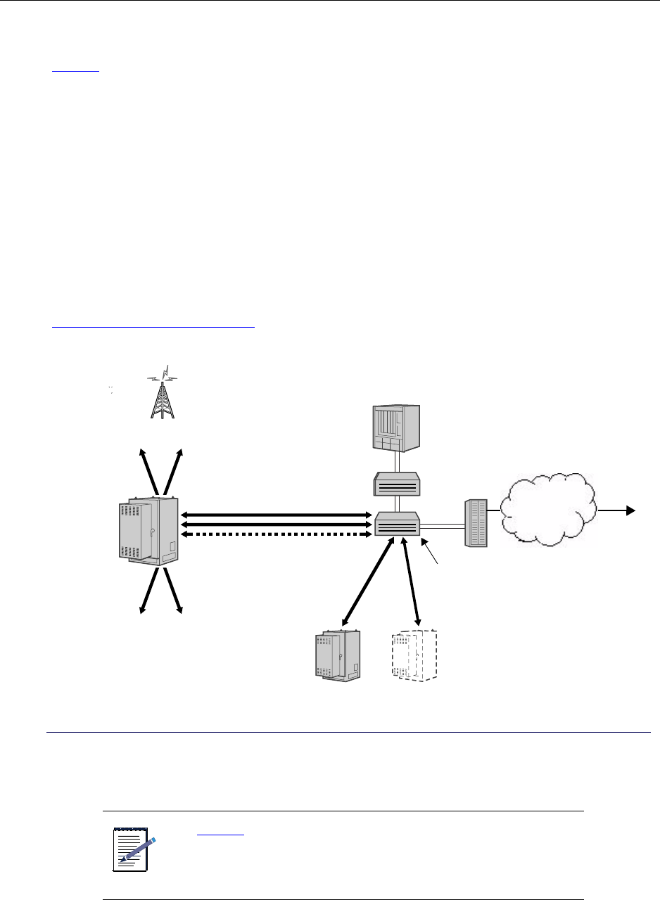
Understanding the network
Figure 1 shows a typical deployment of the IP Radio Node 8000 (IP-RN 8000).
• The IP-RN 8000 is installed at the base of a cell tower and achieves two-way radio communications
with access terminals through RF antennas as appropriate.
• The IP-RN 8000 receives timing signals through primary and optional redundant Global Positioning
System (GPS) antennas.
• The IP-RN 8000 is grounded and connected to a power source.
• Each IP-RN 8000 is connected through backhaul links (up to four T1/E1s or a primary and optional
redundant 10/100 Mbit/sec Ethernet) to an IP Radio Network Controller 8500 (IP-RNC 8500).
These backhaul links carry access terminal data communications and IP-RN 8000 management
communications.
• The IP-RNC 8500 is connected to the Internet through a packet data serving node (PDSN). This link
carries all data communications between the access terminals and the Internet.
For more information on IP-RN 8000 backhaul, antenna, power, ground and other connections, see
Understanding external connections on page 34.
Figure 1 Typical network topology with IP-RN 8000(s), IP-RNC 8500, and other devices and links
NOTE
Figure 1 shows the network connections and devices in a typical
IP-RN 8000 deployment. As with all networks, there are many
variations of deployment and connectivity options. For more
information, see the IP-RAN Network Planning Guide.
IP-RN 8000
Power Ground
RF and GPS antennas
IP-RNC 8500
Ethernet switch
IP router
Other IP-RN 8000s
Backhaul links
PDSN
Internet
Understanding IP-RN 8000 front, side and back views
IP-RN 8000 Installation & Commissioning Guide 3
Understanding IP-RN 8000 front, side and back views
This section introduces the main IP-RN 8000 hardware components and contains the following sections:
•Understanding the cabinet font view on page 3
•Understanding cabinet right side view on page 5
•Understanding the cabinet back view on page 7
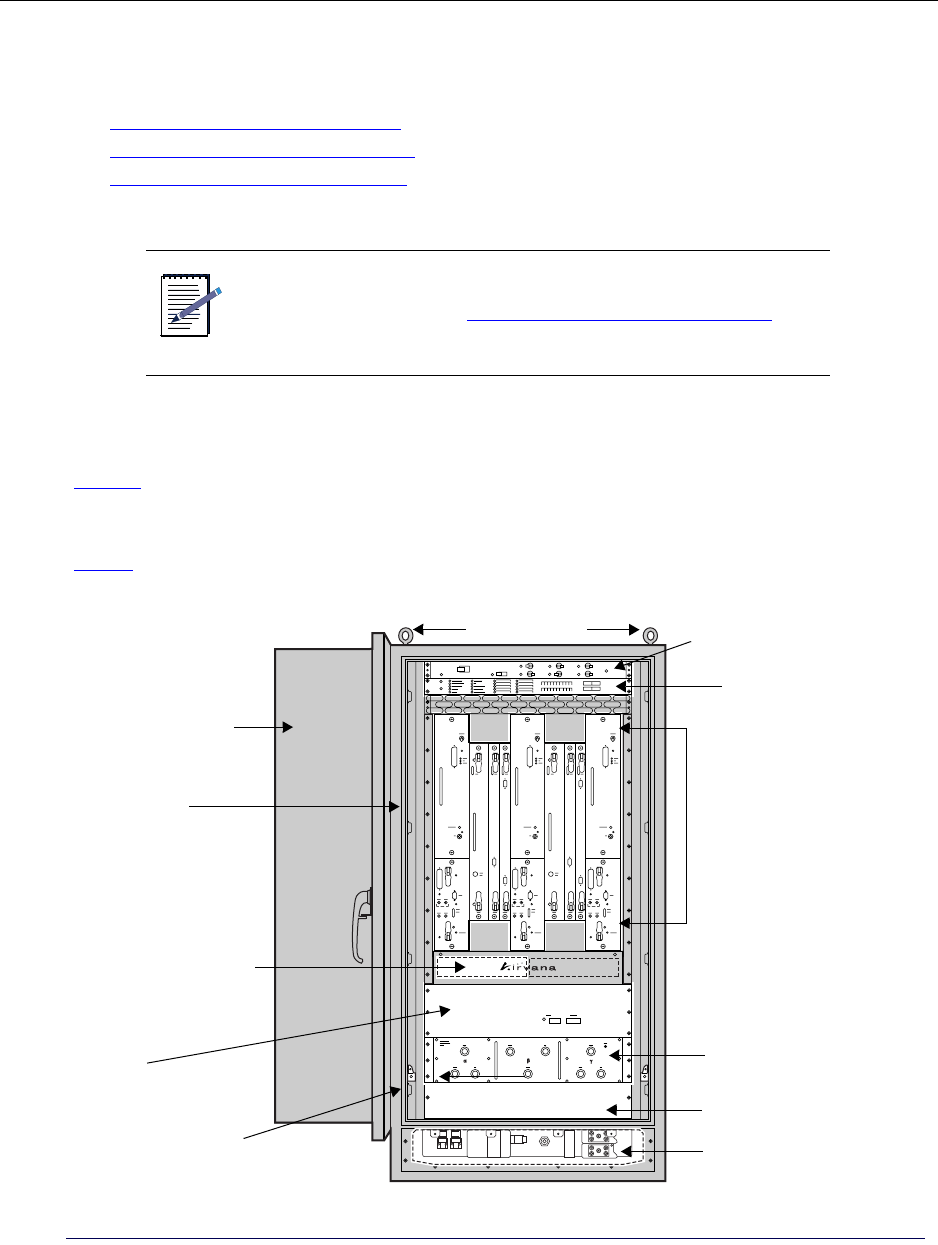
Understanding the cabinet font view
Figure 2 shows the hardware components that are visible when the IP-RN 8000 is viewed from the front
with the door open. This IP-RN 8000 has three Sector Radio Kits and two Digital Module Kits for fail-safe
operation and redundancy.
Table 3 explains all labeled components.
Figure 2 Front view
NOTE
For information about the overall installation processes and
related procedures, see Understanding the installation process on
page 40.
Lifting hooks
Alarm Unit
Power Distribution Unit
Backhaul punch block
Fan unit Antenna Interface Unit
Power terminal access panel (cover removed)
Tech-on-site switch
Door
(behind access panel)
(AIU)
(open)
Module slots for
Sector Radio Kits and
Digital Module Kits
Cabinet
Blank 2U for user
equipment
Power terminal

Chapter 1 ● Introducing the IP-Radio Node 8000
4Release 2.0, 910056 Rev01d
Table 3 Front view components
Component Description
Cabinet The cabinet is the entire node, including the frame, the sheet metal exterior, all modules and
units, etc.
Door (open) The front door features a latching handle that can be padlocked from the outside. The door
also has a locking bar for propping the door open during configuration and maintenance. The
door contains an exhaust vent an intake vent, and a heat exchanger, as well as a laptop shelf
and a container for holding documents and cables.
• See Appendix B, Using the door
Lifting hooks (eye
bolts)
There are four lifting hooks (eye bolts) that you screw into 1/2 inch diameter holes in the four
corners of the top of the cabinet during installation. After the cabinet has been removed from
its shipping palette, the only way to lift it is with these lifting hooks.
Power Distribution
Unit
The Power Distribution Unit (PDU) contains the main power switches and circuits breakers
and other switches and circuit breakers that control power flow to various components.
• See Understanding the Power Distribution Unit on page 27.
Alarm Unit Has LED’s that display the status of 20 alarm circuits, 10 of which are hard wired, 10 of
which can be attached to contact screws on the Alarm Unit. Has 20 on/off switches
controlling all alarms.
• See Understanding the Alarm Unit on page 29.
Module slots Sector Radio Kit modules and Digital Module Kit modules are inserted into these slots. All
modules are field replaceable.
• See Understanding the Sector Radio Kit and the Antenna Interface Unit on page 13.
• See Understanding the Digital Module Kit on page 19
Antenna Interface
Unit (AIU)
Connects Sector Radio Kit modules on the cabinet front side to the RF antenna cables on the
cabinet backside.
• See Understanding the Sector Radio Kit and the Antenna Interface Unit on page 13
Blank 2U for user
equipment
You can install additional equipment into the chassis behind this access panel. The slot
provides 2U space.
Power terminal The terminal to which the power cables are attached.
Tech-on-site switch Used by authorized technicians to suppress door intrusion alarms during normal servicing.
When the switch shaft is pulled forward, the tech-on-site LED lights red and the door/
intrusion alarm is suppressed and its LED remains green.
• See Understanding the tech-on-site switch on page 36
• See Opening the door on page 198
Power terminal
access panel
Contains the power/ground terminal to which the power cables are connected during
installation. Also contains the space through which backhaul cables are fed on the way to the
backhaul punch block. This section is normally hidden behind an access panel cover.
• See Connecting the power supply on page 65.
• See Understanding surge protection and grounding on page 33
Fan Unit Moves air vertically through the chassis from the bottom to the top.
• See Understanding the Fan Unit on page 31
Understanding IP-RN 8000 front, side and back views
IP-RN 8000 Installation & Commissioning Guide 5
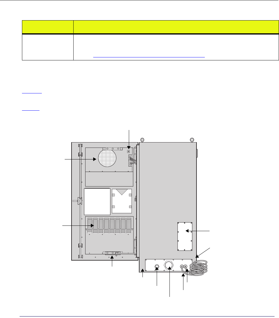
Understanding cabinet right side view
Figure 3 shows the hardware components that are visible when you view the IP-RN 8000 from the right side
with the front door open.
Table 4 explains all labeled components.
Figure 3 Right side view with the front door open
Backhaul punch
block
A punch block for connecting the T1/E1 and Ethernet physical lines for the backhaul network
after they have been routed through the backhaul conduit and through cabinet.
• See Understanding the backhaul punch block and switch on page 32
Table 3 Front view components (continued)
Component Description
Doc.
Air flow vent
holder
PC shelf
Door lock-open bar
Power cable access port
Backhaul cable access port Lightning ground wire
Optional antenna
antenna access panel
Door (open) Lifting hooks
Side ground connectors
(closed)
Air flow vent
Cabinet ground wire
(behind coils)
Heat exchanger LEDs

Chapter 1 ● Introducing the IP-Radio Node 8000
6Release 2.0, 910056 Rev01d
Table 4 Right side view components
Hardware feature Description
Door (open) The front door is shown all the way open.
See Appendix B, Using the door
Heat exchanger LEDs Four LEDs that indicate heat exchanger status.
Lifting hooks (eye bolts) There are four lifting hooks (eye bolts) that you screw into 1/2 inch diameter
holes in the four corners of the top of the cabinet during installation. After
the cabinet has been removed from its shipping palette, the only way to lift it
is with these lifting hooks.
Optional antenna cable access panel One of four possible access panels into which the Rox SystemTM cabinet seal
can be installed. The Rox System Cabinet seal threads RF and GPS antenna
cables into the IP-RN 8000 chassis and seals off external environmental
conditions. You can perform the installation using an access panel at the
bottom of either side, at the bottom of the back, or at the top of the back. The
standard installation uses the top-back antenna access panel.
See Installing the Rox System cabinet seal on page 94
Side ground connectors Connect to site grounding infrastructure for additional grounding protection
as needed. These are dual threaded lug holes with 1/4-20 threads.
See Understanding surge protection and grounding on page 33
Cabinet ground wire A copper coil that provides the main grounding connection for the
cabinet.The coil must be connected to an earth ground system that meets all
local codes and requirements.
See Understanding surge protection and grounding on page 33
Lightning ground wire A copper coil that provides the grounding connection for the RF and GPS
antennas. This is a secondary surge suppression system; an external primary
surge suppression system is required. The coil must be connected to an earth
ground system that meets all local codes and requirements.
See Understanding surge protection and grounding on page 33
Power cable access port Feed power cable through this port for internal connection into the power
terminals. Optionally attach 3 inch conduit as appropriate and required.
See Connecting the power supply on page 65.
Backhaul cable access port Feed T1/E1 or Ethernet backhaul cables through this port for internal
connection into the Backhaul Punch Block. Backhaul cables can optionally
be combined with power cable and be fed with the power cable through the
power cable access port. Optionally attach 1 inch conduit as appropriate and
required.
See Chapter 5, Connecting the backhaul.
Door lock-open bar Locks the door into an open position.
See Opening the door on page 198
Air flow vents Vents for the internal air flow loop.
See Understanding cabinet air flow on page 37
Doc. holder A holder for documents and extra cables.
Understanding IP-RN 8000 front, side and back views
IP-RN 8000 Installation & Commissioning Guide 7
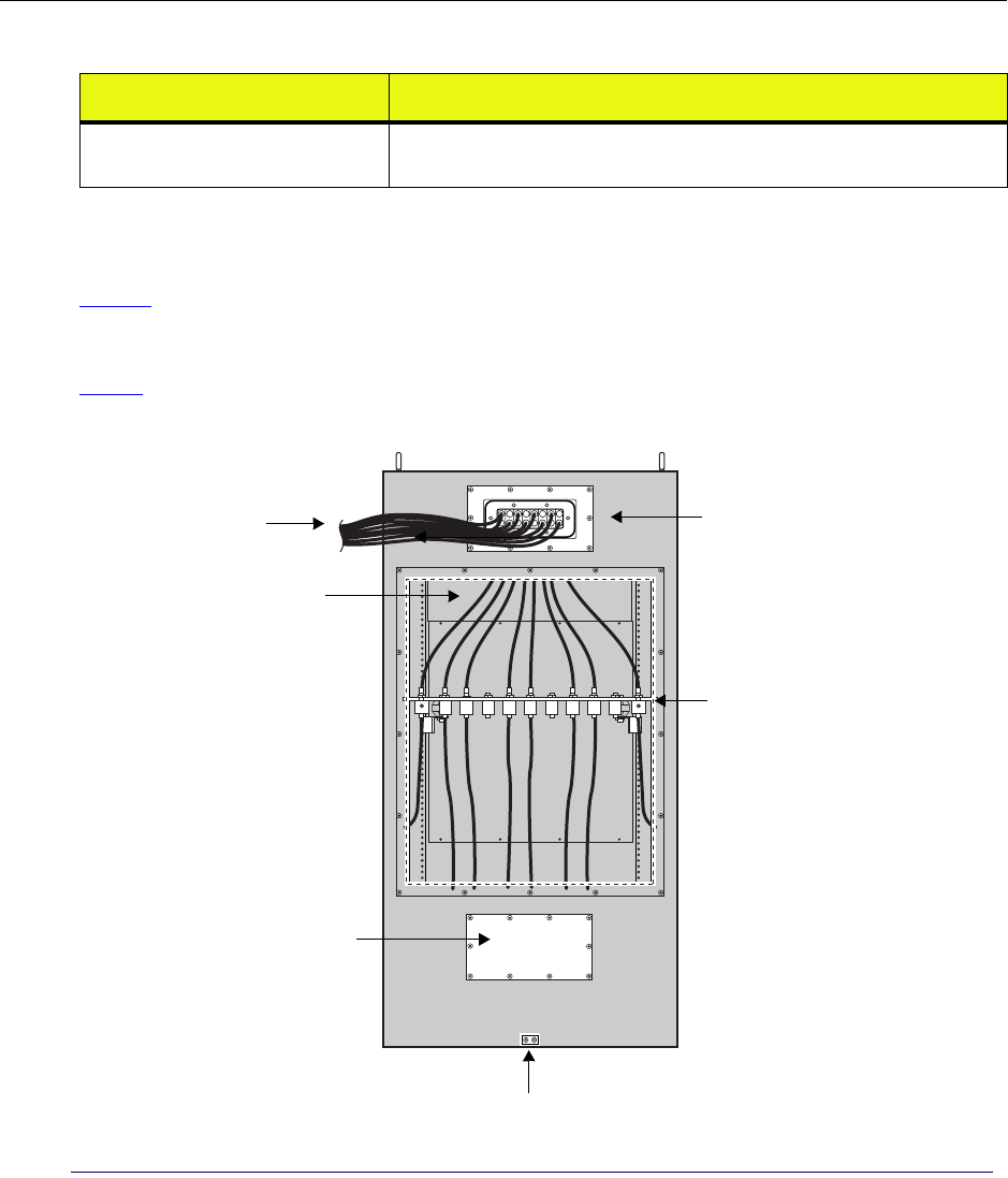
Understanding the cabinet back view
Figure 4 shows the hardware components that are visible when you view the IP-RN 8000 from back side.
This view shows the Rox System cabinet seal already installed and the surge suppressor access panel
removed.
Table 5 explains all labeled components.
Figure 4 Rear view with the Rox System cabinet seal and antenna cables installed and with the surge
suppressor access panel removed
PC shelf (closed) A shelf for holding a laptop PC used for a terminal connection to the node.
Shown in the closed position.
Table 4 Right side view components (continued)
Hardware feature Description
Rox System cabinet
Lifting hooks
Surge suppression bar
Optional antenna access panel
Rear ground connectors
RF and GPS antenna cables
exiting cabinet after
RF and GPS antenna cables
seal (installed)
(inside cabinet)
(access panel removed)
installation

Chapter 1 ● Introducing the IP-Radio Node 8000
8Release 2.0, 910056 Rev01d
Table 5 Rear view
Item Description
RF and GPS antenna cables The bundle of Global Positioning System (GPS) and radio frequency (RF)
transmit/receive antenna cables exiting the IP-RN 8000.
•See Chapter 6, Connecting antennas
Lifting hooks (eye bolts) There are four lifting hooks (eye bolts) that you screw into 1/2 inch diameter
holes in the four corners of the top of the cabinet during installation. After
the cabinet has been removed from its shipping palette, the only way to lift it
is with these lifting hooks.
Rox System cabinet seal (installed) The Rox System Cabinet seal threads antenna cables into the IP-RN 8000
chassis and seals off external environmental conditions. The Rox System
cabinet seal is installed during IP-RN 8000 installation.
•See Installing the Rox System cabinet seal on page 94.
Surge suppression bar (access panel
removed)
External antenna cables are attached to the connectors on the surge
suppression bar. This grounded bar and its surge suppressor connectors
constitute a secondary surge protection system that provides additional
protection from power surges and lightening strikes. A primary external
surge protection equipment is required.
•See Understanding the antenna installation process on page 86
Rear ground connectors Connect to site grounding infrastructure for additional grounding protection
as needed.
•See Understanding surge protection and grounding on page 33
Antenna access panel One of four possible access panels into which the Rox System cabinet seal
can be installed. The Rox System Cabinet seal threads antenna cables into
the IP-RN 8000 chassis and seals off external environmental conditions. You
can perform the installation using an access panel at the bottom of either
side, at the bottom of the back, or at the top of the back. The standard
installation uses the top-back antenna access panel.
•See Installing the Rox System cabinet seal on page 94v
RF and GPS antenna cables (inside
cabinet)
The number of RF (transmit and receive) and GPS antenna cables depends
on the particular installation. This part of the figure shows the cables routing
down from the Rox System cabinet seal and connecting to the surge
protection bar.
•See Understanding surge protection and grounding on page 33.
•See Connecting GPS and RF antennas on page 96
RF and GPS antenna cables (exiting
cabinet)
The number of RF (transmit and receive) and GPS antenna cables depends
on the particular installation. This part of the figure shows the antenna cables
exiting the cabinet through the Rox System cabinet seal, on their way to
connection with antenna cables on the cell tower.
•See Connecting GPS and RF antennas on page 96
Understanding IP-RN 8000 front, side and back views
IP-RN 8000 Installation & Commissioning Guide 9
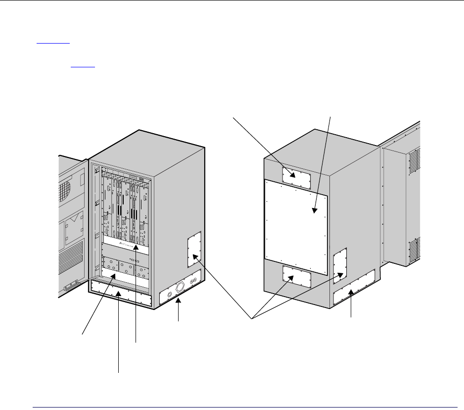
Understanding access panels
Figure 5 shows the 10 access panels. There are three access panels on the front, two on each side, and three
on the back. These access panels provide access to internal components and allow for different installation
options. Table provides descriptions of each access panel and the explains the standard installation
documented in this guide.
Figure 5 Access panels
Standard antenna
access panel
Right side cable
access panel
Left side
cable access panel
Optional antenna
access panels
Power terminal
Surge Protection Bar
access panel
Punch block
access panel
access panel
User equipment
access panel

Chapter 1 ● Introducing the IP-Radio Node 8000
10 Release 2.0, 910056 Rev01d
Table 6 Access panels
Access panel Description
Standard antenna cable access panel There are four access panels into which the Rox System Cabinet Seal can be
installed. (The Rox System Cabinet Seal is the environmentally sealed unit
through which RF and GPS antenna cables enter the cabinet.) This
installation guide explains how to install the Rox System Cabinet seal into
the standard antenna cable access panel at the top of the back of the cabinet.
Optional antenna cable access
panels
The Rox System Cabinet Seal can optionally be installed into any of three
other antenna access panels. However, these installation options required
non-standard configurations of internal components, and in these cases the
cabinet must be special ordered.
Right side cable access panel There are two access panels through which the power cable, the the backhaul
cable(s), and the alarm cables (if any) can enter the cabinet, one on the right
side, one on the left side. The right side is the standard configuration.This
installation guide explains how to install all systems using the right side
access panel. You can optionally route the backhauls and the power cables
through the left side access panel without special ordering the cabinet as the
internal configurations are identical. This access panel also provides access
to cabinet mounting bolts.
Left side cable access panel The left side has an optional access panel through which the power,
backhaul, and alarms cables can optionally enter the cabinet. This access
panel also provides access to cabinet mounting bolts.
Power terminal access panel Provides access to the power cable terminals and the routing harness for the
backhaul cables.
User equipment access panel Behind this access panel is a chassis placeholder for optional installation of
customer equipment. There is 2U space.
Surge Protection Bar access panel Provides access to the surge Protection bar. All antennas (RF and GPS) must
be connected to the surge protection bar during installation.
Punch block access panel Provides access to the Backhaul Punch Block and the Alarm Punch Block
(reserved for future use). Backhaul connections must be wired to the
Backhaul Punch Block during installation.
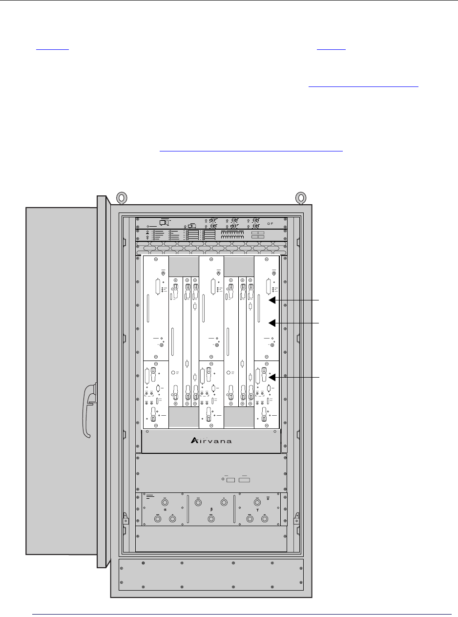
Understanding module slot numbering
IP-RN 8000 Installation & Commissioning Guide 11
Understanding module slot numbering
Figure 6 shows the nine vertical slots for field replaceable modules. See Table 7 on page 12 for details about
which modules are installed into which slots for various system configurations.
• Slots 1, 5, and 9 are horizontally divided into a top part and a bottom part and contain the two modules
that make up the Sector Radio Kit: the RM and PA modules. See Understanding radio sectors on
page 13.
You can install one, two or three Sector Radio Kits.Each Sector Radio Kit corresponds to a radio sector.
Radio sectors are named alpha, beta, and gamma.
• Slots 2, 3, 4, 6, 7, and 8 contain the modules that make up the Digital Module Kit: the TFU, BIO/SC,
and 1xDOM modules. See Understanding Digital Module Kit redundancy on page 20.
You can install one or two Digital Module Kits. Two Digital Module Kits provide additionally hardware
and software redundancy for service continuity through failures.
Figure 6 Slot numbers
1234 56789 Slot numbers
Top slots (1, 5 and 9 only)
Bottom slots (1, 5 and 9 only)

Chapter 1 ● Introducing the IP-Radio Node 8000
12 Release 2.0, 910056 Rev01d
Understanding replaceability terms
This guide describes whether modules and other items are “field replaceable,” “hot-swappable,” and
whether replacing them entails any service disruption. Here are the definitions of these terms:
• “Field-replaceable” means the item can be replaced without returning the entire network element to
Airvana. Field-replaceable items may or may not be hot-swappable.
• “Hot-swappable” means the item can be replaced without powering down other modules or the cabinet
as a whole. Hot swappable items may or may not cause service disruption when swapped out.
• “Service disrupting” means replacing the item causes some break in the continuity of service to at least
some user sessions.
Table 7 IP-RN 8000 slot numbering
Install Module(s) In this slot
Sector Radio Kit for alpha sector PA 1— top *
RM 1 — bottom *
Primary Digital Module TFU 2
BIO/SC 3
1xDOM 4
Sector Radio Kit for beta sector PA 5 — top *
RM 5 — bottom *
Redundant Digital Module TFU 6
BIO/SC 7
1xDOM 8
Sector Radio Kit for gamma sector PA 9 — top *
RM 9 — bottom *
* Slots 1, 5 and 9 are divided by a horizontal separator into a top part and a bottom part.

Understanding the Sector Radio Kit and the Antenna Interface Unit
IP-RN 8000 Installation & Commissioning Guide 13
Understanding the Sector Radio Kit and the Antenna
Interface Unit
This section describes the Sector Radio Kit and the Antenna Interface Unit (AIU). This section contains the
following subsections:
•Understanding radio sectors on page 13
•Understanding the Sector Radio Kit on page 14
•Understanding the Radio Module on page 14
•Understanding the Power Amplifier module on page 16
•Understanding the Antenna Interface Unit module on page 17
Understanding radio sectors
The 360 degrees of horizontal radio transmission/reception is often divided into three 120 degree radio
sectors labeled: alpha, beta, and gamma. Different deployments may use a different numbers of sectors, and
each sector can provide a different amount of radio coverage. For example, an omni antenna can provide 360
degrees of radio coverage and only uses a single sector. Each sector requires:
• Installation of a Sector Radio Kit.
• Connection of the Sector Radio Kit RF transmit and receive antennas to the cell tower antenna cables
through the Antenna Interface Unit (AIU)
You can install one, two, or three Sector Radio Kits depending on deployment requirements. Typical
deployments use all three sectors and provide 360 degree radio coverage.
There is no requirement that single-sector deployments must use the alpha sector. Sectors can be installed
and deployed in any order. However, as a convention in this guide, single sector deployments always use the
alpha sector.
Table 8 shows the slots into which you install Sector Radio Kits for one, two, and three sectors of radio
coverage.
NOTE
For information about installation processes and procedures, see
Understanding the installation process on page 40.
Table 8 Radio sector installation guidelines
Sectors utilized Install Radio Sector Kits into these slots
Alpha 1
Beta 5
Gamma 9
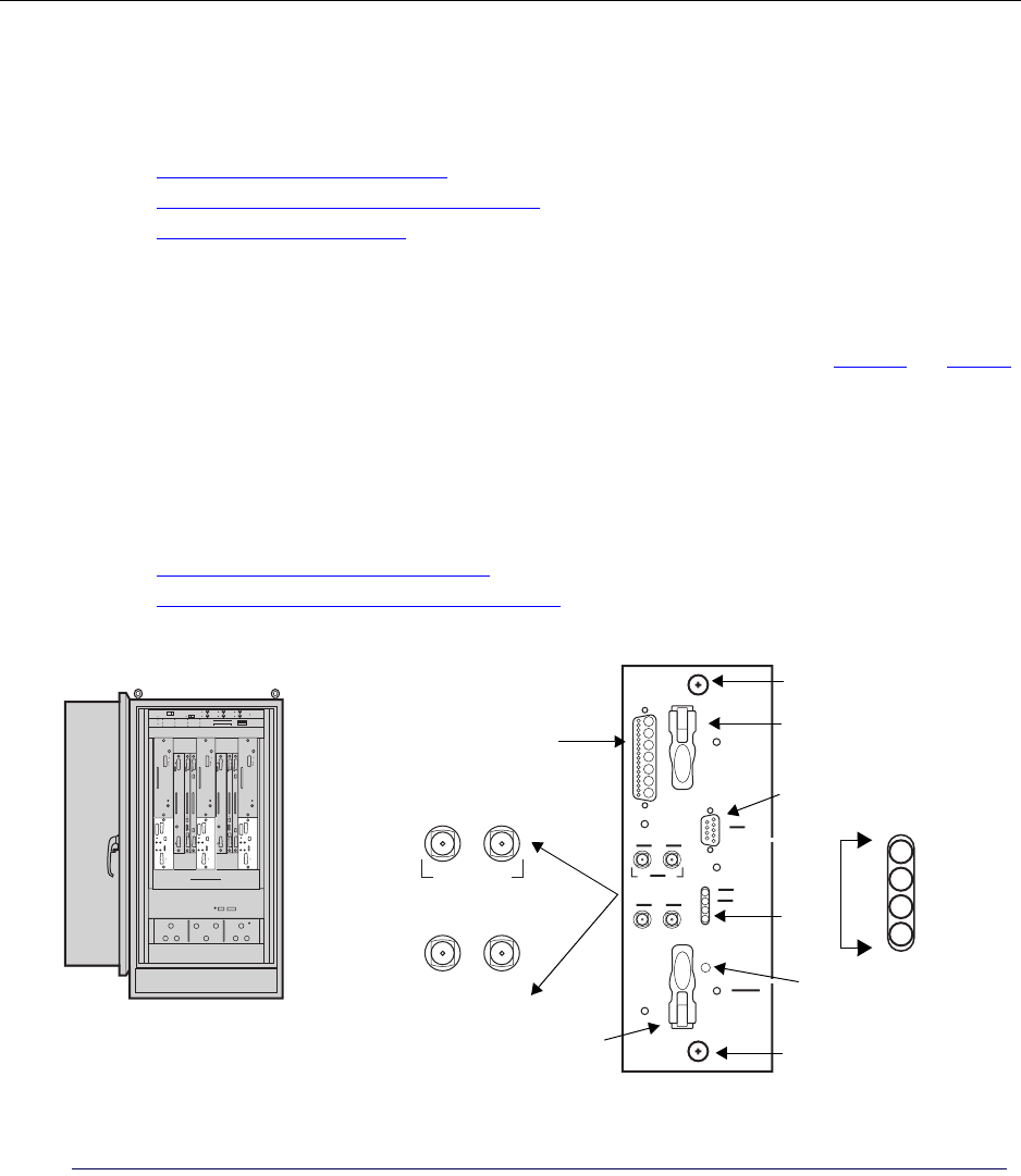
Chapter 1 ● Introducing the IP-Radio Node 8000
14 Release 2.0, 910056 Rev01d
Understanding the Sector Radio Kit
The Sector Radio Kit consists of two field-replaceable modules, the Radio Module (RM) and the Power
Amplifier (PA). The two modules are installed in the appropriate cabinet slots and cable connections must be
completed.
• See Understanding the Radio Module on page 14.
• See Understanding the Power Amplifier module on page 16.
• See Installing a Power Amplifier on page 105.
Understanding the Radio Module
The Radio Module (RM) is one of two modules that make up the Sector Radio Kit. See Figure 7 and Table 9.
The RM provides modulation, demodulation, and radio frequency conversion services for a single radio
sector. Typical deployments supporting 360 degree radio coverage require three RMs. The RM is installed in
the bottom part of slots 1, 5, or 9, depending on the sector.
The RM is field-replaceable and hot swappable. Replacing an active RM in the field is service disrupting for
its sector.
For information about installing the RM module:
• See Understanding the installation process on page 40.
• See Understanding the module installation process on page 104.
Figure 7 Radio Module
TX output to PA
Top latch
LEDs
Power
Alarm
Sample
RX0 RX1
RX0 RX1
Craft/serial port
Captive screw
Captive screw
RMs (Radio Modules)
bottom of slots 1, 5, and 9 Bottom latch
Reset button

Understanding the Sector Radio Kit and the Antenna Interface Unit
IP-RN 8000 Installation & Commissioning Guide 15
Table 9 Radio Module (RM) faceplate components
Component Description
Latches and screws Top and bottom latches Close to insert the RM in its slot.
Open to remove the RM from its slot.
Captive screws Tighten to secure the module into its slot.
Loosen before removing the RM from its slot.
LEDs Power Lights green when the RM is receiving power. Flashes during
module initialization.
Alarm Lights red when the RM is in an alarm state.
Interfaces RX0 Connects to the RX0 interface for this radio sector on the
AIU. Carries one of two received RF signals. Connector type:
SMA receptacle (female).
RX1 Connects to the RX1 interface for this radio sector on the
AIU. Carries one of two received RF signals. Connector type:
SMA receptacle (female).
RX0 (Sample) Provides a receiver injection port for use with externally
connected mobile test radios or test equipment. Connector
type: SMA receptacle (female).
RX1 (Sample) Provides a receiver injection port for use with externally
connected mobile test radios or test equipment. Connector
type: SMA receptacle (female).
TX output to PA Connects transient RF signals to/from the PA module using
Airvana cable installed during the installation process. Also
carries control information to the PA and status information
from the PA to the RM. Connector type: SMA receptacle.
Contour type: blind mate.
Craft/serial port Connects to a management PC for CLI access to the RM.
DB-9 interface. The serial port speed is 115,200 bit/second.
For information on the DB-9 pin-out, see Table 35 on
page 196.
Reset button Recessed button Pressing this recessed button resets the RM processor.
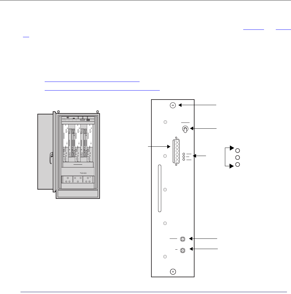
Chapter 1 ● Introducing the IP-Radio Node 8000
16 Release 2.0, 910056 Rev01d
Understanding the Power Amplifier module
The Power Amplifier (PA) is one of two modules that make up the Sector Radio Kit. See Figure 8 and Table
10. PAs install in upper slots 1, 5, and 9, depending on the radio sector. The PA supports a single sector and
a single corresponding antenna. Typical deployments support three sectors and use three PAs.
The PA is field-replaceable and hot swappable. Replacing an active PA in the field is service disrupting for
its sector.
For information about installing the PA module:
• See Understanding the installation process on page 40.
• See Understanding the module installation process on page 104.
Figure 8 Power Amplifier
Power Amplifier (PA) Modules
LEDs
Power
Fail
RF On
TX sample
TX to AIU
TX input
Captive screw
Power switch
from RM
Top of slots 1, 5, and 9

Understanding the Sector Radio Kit and the Antenna Interface Unit
IP-RN 8000 Installation & Commissioning Guide 17
Understanding the Antenna Interface Unit module
The Antenna Interface Unit (AIU) is a pre-installed unit residing in the lower part of the front of the cabinet.
See Figure 9 and Table 11.
The AIU contains filters and duplexors.
The AIU is divided into three sectors, one for each radio sector, from left to right: alpha, beta, and gamma.
Each radio sector has two receive antenna connectors and one transmit antenna connector that connect to
corresponding connectors on the appropriate Sector Radio Kit.
This AIU has nine ports on the faceplate, three for each sector. During installation, you connect these
faceplate ports Sector Radio Kits.
The AIU also has ports on the rear side that you cannot see. There are two versions of the AIU that differ in
the number of rear-facing ports: the 6-port AIU and the 9-port AIU. The rear-facing ports are connected to
the surge suppression bar, and then to RF antenna cables. The 6-port AIU is the standard configuration.
The AIU is field-replaceable but it is not hot swappable. Therefore, replacing the AIU is service disrupting
for all sectors.
Table 10 Power Amplifier faceplate components
Component Description
Captive screw(s) Tighten to secure the PA in its slot.
Loosen to remove the PA from its slot.
Power switch Flip up to turn on power to the PA.
Push down to turn off power to the PA.
LEDs Power Lights green when the PA receives power.
Fail Lights red when the PA has failed.
RF On Lights green when the RF is applied.
Interfaces TX (Sample) Connects to an external spectrum analyzer. Carries a duplicate of
the TX signal for sampling purposes. Connector type: SMA
receptacle
TX (to AIU) Connects to the TX interface on the AIU using a cable installed
during the installation process. Transmits the radio signal from the
PA to the AIU for filtering and transmission from the cell tower
antenna. Connector type: SMA receptacle.
TX input from RM Receives the transmit radio signal generated by RM. The PA
amplifies the signal and transmits it to the AIU over the TX (to
AIU) interface. Also carries control information from the RM to
the PA and status information from the PA to the RM. Connector
type: blind mate.
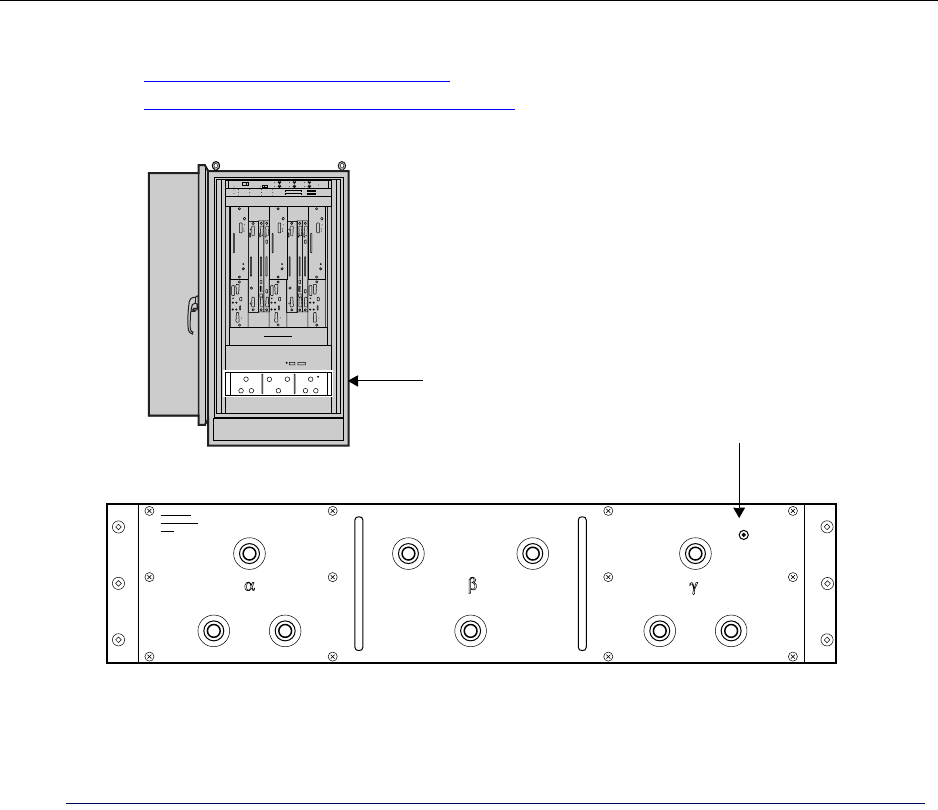
Chapter 1 ● Introducing the IP-Radio Node 8000
18 Release 2.0, 910056 Rev01d
For information about installing the AIU:
• See Understanding the installation process on page 40.
• See Understanding the module installation process on page 104.
Figure 9 Antenna Interface Unit
AIU (Antenna Interface Unit)
RX1
RX0 TX
RX1
RX0 TX
RX0
RX1
TX
Alpha sector
Beta sector
Gamma sector
ESD jack
Connects to
slot 1 Sector
Connects to
slot 5 Sector
Connects to
slot 9 Sector
Radio Kit Radio Kit Radio Kit

Understanding the Digital Module Kit
IP-RN 8000 Installation & Commissioning Guide 19
Understanding the Digital Module Kit
This section describes the Digital Module Kit and contains the following sections:
•Understanding Digital Module Kit modules on page 19
•Understanding Digital Module Kit redundancy on page 20
•Understanding the Timing Frequency Unit module on page 21
•Understanding the Base Input Output/System Controller module on page 22
•Understanding the 1xDOM module on page 25
Understanding Digital Module Kit modules
The Digital Module Kit consists of three modules:
• Timing Frequency Unit (TFU)
See Understanding the Timing Frequency Unit module on page 21.
• Base Input Output/System Controller (BIO/SC)
See Understanding the Base Input Output/System Controller module on page 22
• 1xDOM
See Understanding the 1xDOM module on page 25.
All three modules must be installed for each Digital Module Kit. One or two Digital Module Kits can be
installed depending on the need for system redundancy.
• See Understanding Digital Module Kit redundancy on page 20
Table 11 Antenna Interface Unit faceplate components
Component Description
Interfaces Alpha
sector
RX 0 Connects to the RX0 connector on the RM in slot 1.
RX 1 Connects to the RX1 connector on the RM in slot 1.
TX Connects to the TX connector on the PA in slot 1.
Beta
sector
RX 0 Connects to the RX0 connector on the RM in slot 5.
RX 1 Connects to the RX1 connector on the RM in slot 5.
TX Connects to the TX connector on the PA in slot 5.
Gamma
sector
RX 0 Connects to the RX0 connector on the RM in slot 9.
RX 1 Connects to the RX1 connector on the RM in slot 9.
TX Connects to the TX connector on the PA in slot 9.
ESD jack This is the jack for the electric static discharge wrist strap that must be worn and plugged in here at all
times when installing, servicing, or touching the inside of the IP-RN 8000. Warning: Failure to wear
a wrist strap that is plugged into this jack can result in service outages and equipment damage.
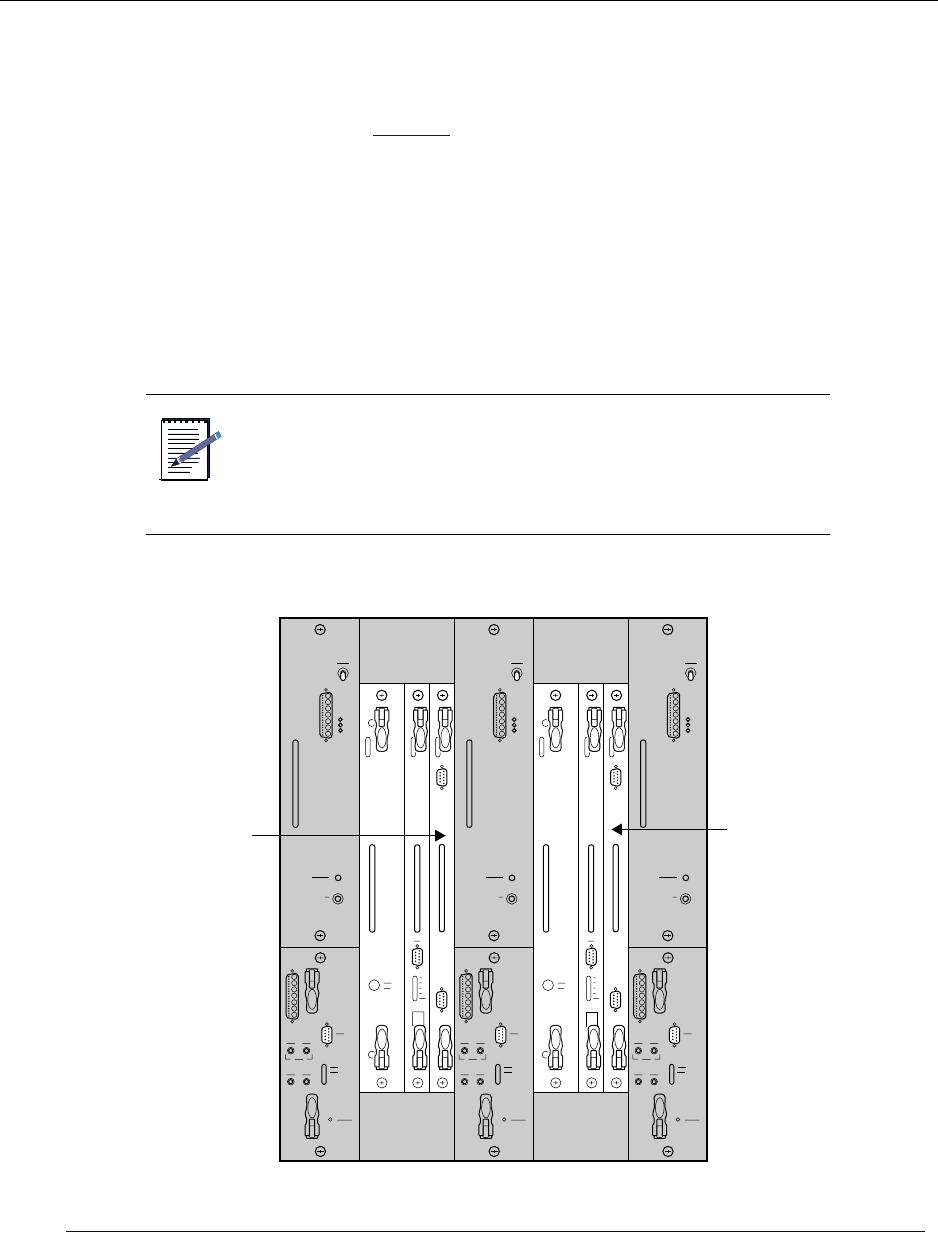
Chapter 1 ● Introducing the IP-Radio Node 8000
20 Release 2.0, 910056 Rev01d
Understanding Digital Module Kit redundancy
You can install one or two Digital Module Kits. Only a single (primary) Digital Module Kit is required for
non-redundant operation. This non-redundant configuration provides less protection from potential faults in
Digital Module Kit components. See Figure 10.
For non-redundant systems, use the following installation guidelines:
• The primary Digital Module Kit modules install in slots 2, 3, and 4.
• The primary GPS antenna cable connects to a GPS antenna.
For redundancy, install two Digital Module Kits.
• The secondary Digital Module Kit modules install in slots 6, 7 and 8
• The secondary GPS antenna cable connects to a second GPS antenna.
Figure 10 Primary and redundant Digital Module Kits with slot numbers for each module
NOTE
There is no hardware or software requirement that the primary
Digital Module Kit is installed in slots 2, 3, and 4 and secondary
in 6, 7, and 8. The primary can be installed in slots 6, 7, and 8,
and the secondary in slots 2, 3, and 4. However, this guideline is
followed throughout this guide for clarity.
TFU BIO/SC txDOM TFU BIO/SC txDOM
Slot 1
24
Slot 5 Slot 9
6783
Primary Redundant
TFU
BIO/SC
TFU
BIO/SC
Digital
Digital
Module Module
1xDOM
1xDOM
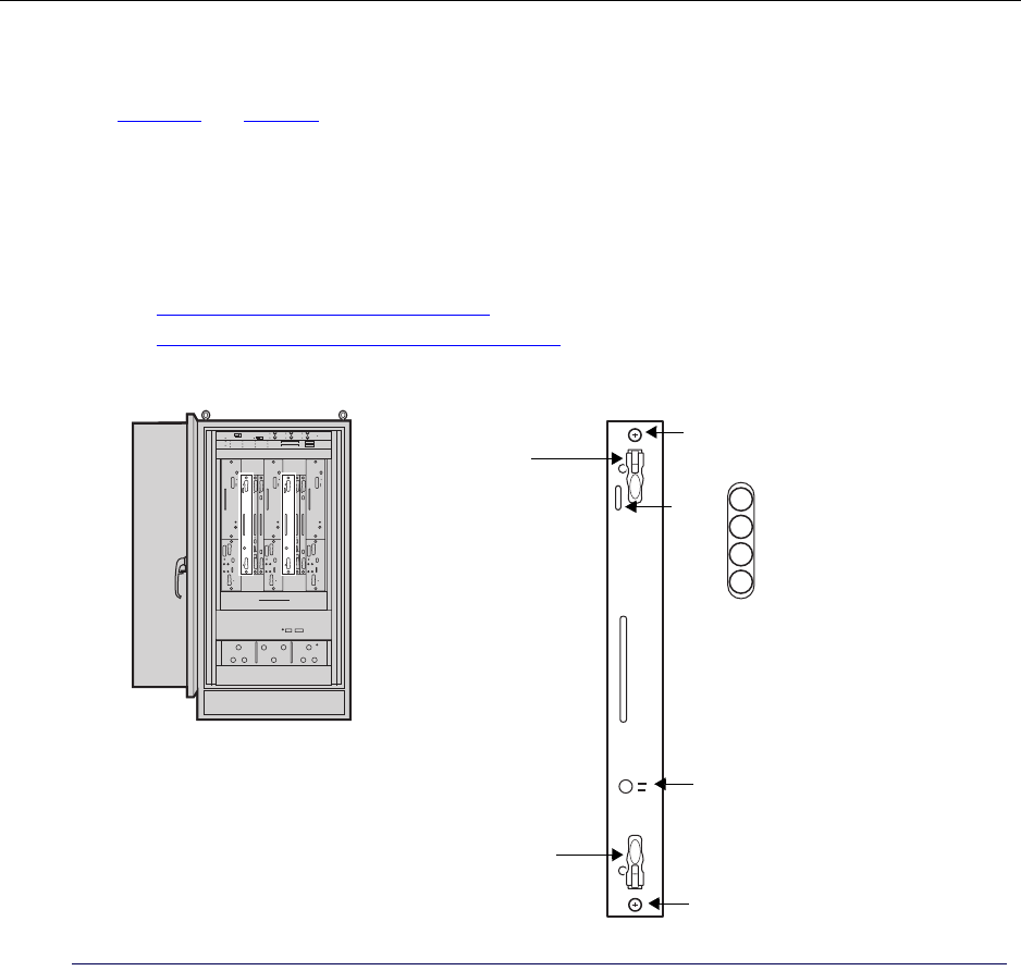
Understanding the Digital Module Kit
IP-RN 8000 Installation & Commissioning Guide 21
Understanding the Timing Frequency Unit module
The Timing Frequency Unit (TFU) provides system timing from Global Positioning System (GPS) antenna.
See Figure 11 and Table 12.
The primary TFU module installs in slot 2. The optional redundant TFU installs in slot 6.
The TFU is field-replaceable and hot swappable. Hot swapping a TFU is service disrupting if it is the active
TFU in a redundant configuration. Therefore switching service to the standby TFU in redundant systems
before replacing the module is recommended.
For information about installing the TFU:
• See Understanding the installation process on page 40.
• See Understanding the module installation process on page 104.
Figure 11 Timing Frequency Unit
TFU
Power
Alarm
Standby
Active
Timing Frequency Units (TFUs)
slot 2 (primary) & slot 6 (redundant)
Captive screw
Captive screw
Top latch
Bottom latch
LEDs
10 Mhz Out

Chapter 1 ● Introducing the IP-Radio Node 8000
22 Release 2.0, 910056 Rev01d
Understanding the Base Input Output/System Controller module
The Base Input Output/System Controller (BIO/SC) provides backhaul support, system control services, and
timing distribution to internal IP-RN 8000 components. See Figure 12 and Table 13.
The primary BIO/SC installs in slot 3. The optional redundant BIO/SC installs in slot 7.
The BIO/SC is field-replaceable and hot swappable. Hot swapping a BIO/SC is service disrupting if it is the
active BIO/SC in a redundant configuration. Therefore switching service to the standby BIO/SC in
redundant systems before replacing the module is recommended.
For information about installing the BIO/SC module:
• See Understanding the installation process on page 40.
• See Understanding the module installation process on page 104.
Table 12 TFU faceplate components
Component Description
Latches and screws Top and bottom latches Close to insert the TFU in its slot.
Open to remove the TFU from its slot.
Captive screw(s) Tighten to secure the TFU in its slot.
Loosen before removing the TFU from its slot.
LEDs Power Lights green when the TFU receives power.
Alarm Lights red when the TFU is in an alarm state.
Standby Lights amber when the TFU is in standby mode in a
redundant configuration.
Active Lights green when the TFU is in active mode in a redundant
configuration.
10 MHz Out This is a 10 MHz sample port for connecting external test equipment.
Connector type: BNC.
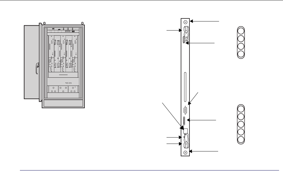
Understanding the Digital Module Kit
IP-RN 8000 Installation & Commissioning Guide 23
Figure 12 BIO/SC module
BIO/SC
Power
Alarm
Standby
Active
L1
L2
L3
L4
DB-9 craft/serial port
BIO/SCs in slot 3 (primary)
Top latch
and slot 7 (redundant)
Enet
Ethernet craft port
LEDs
Captive screw
LEDs
Bottom latch
Captive screw
Reset button

Chapter 1 ● Introducing the IP-Radio Node 8000
24 Release 2.0, 910056 Rev01d
Table 13 BIO/SC faceplate components
Component Description
Latches and screws Top and bottom latches Close when inserting the BIO/SC in its slot
Open when removing the BIO/SC from its slot
Captive screw(s) Tighten when securing the BIO/SC in its slot
Loosen removing the BIO/SC from its slot
LEDs Power Lights green when the BIO/SC receives power.
Alarm Lights red when the BIO/SC is in an alarm state.
Standby Lights amber when the BIO/SC is in standby mode in a
redundant configuration.
Active Lights green when the BIO/SC is in active mode in a
redundant configuration.
L1 Lights when the first of up to four T1/E1 backhaul links has a
“link up” status
L2 Lights when the second of up to four T1/E1 backhaul links
has a “link up” status.
L3 Lights when the third of up to four T1/E1 backhaul links has a
“link up” status
L4 Lights when the fourth of up to four T1/E1 backhaul links has
a “link up” status.
Enet Lights when the Ethernet backhaul has a “link up” status.
Craft ports Serial craft, Female DB-9 Serial port for terminal connection and Command Line
Interface (CLI) control of the node. Speed 38,400 bit/second.
For information on the DB-9 pin-out, see Table 35 on
page 196.
Ethernet craft An RJ-45 modular jack Ethernet interface for local craft
Ethernet connectivity.
Reset button Recessed button Pressing this button resets the BIO/SC processor.
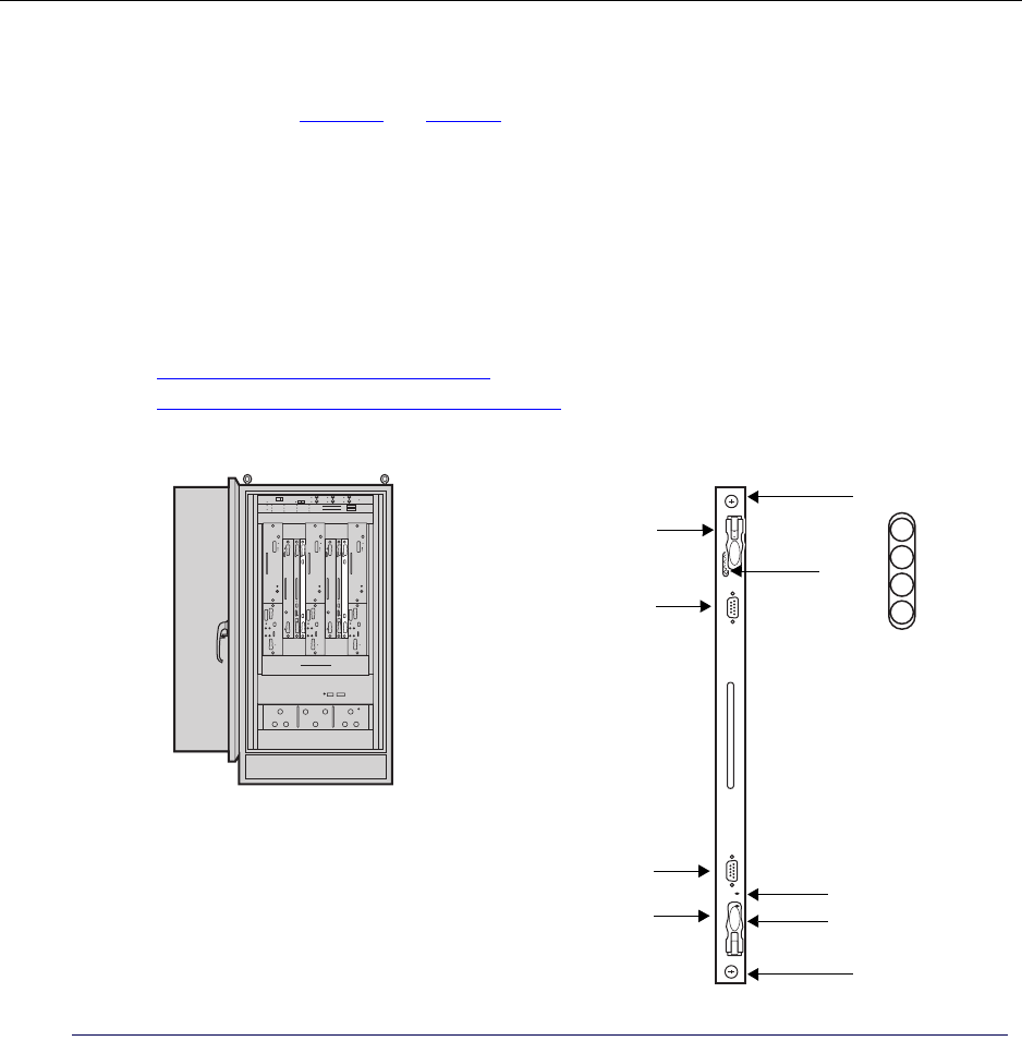
Understanding the Digital Module Kit
IP-RN 8000 Installation & Commissioning Guide 25
Understanding the 1xDOM module
The 1xDOM (1xEV Data Only Modem) processes packets between the backhaul network and the 1xEV-DO
baseband interfaces. See Figure 13 and Table 14.
The 1xDOM uses Qualcomm technology and features FLM (Forward Link Module) and RLM (Reverse
Link Module) processors. The 1xDOM receives timing synchronization from the TFU and the BIO/SC.
The primary 1xDOM installs in slot 4. The optional redundant 1xDOM installs in slot 8.
The 1xDOM is field-replaceable and hot swappable. Hot swapping a 1xDOM is service disrupting if it is the
active 1xDOM in a redundant configuration. Therefore switching service to the standby 1xDOM in
redundant systems before replacing the module is recommended.
For information about installing the 1xDOM module:
• See Understanding the installation process on page 40.
• See Understanding the module installation process on page 104.
Figure 13 1xDOM module
txDOM
1xDOM
Power
Alarm
Standby
Active
FLM craft/serial port
slot 4 (primary) & slot 8 (redundant)
Top latch
LEDs
RLM craft/serial port
Bottom latch
Captive screw
Captive screw
FLM reset button
RLM reset button

Chapter 1 ● Introducing the IP-Radio Node 8000
26 Release 2.0, 910056 Rev01d
Table 14 1xDOM faceplate components
Component Description
Latches and screws Top and bottom latches Close when installing the 1xDOM in its slot.
Open when removing the 1xDOM from its slot.
Captive screw(s) Tighten when securing the 1xDOM in its slot.
Loosen when removing the 1xDOM from the slot.
LEDs Power Lights green when the 1xDOM receives power.
Alarm Lights red when the 1xDOM is in an alarm state.
Standby Lights amber when the 1xDOM is in standby mode in a
redundant configuration.
Active Lights green when the 1xDOM is in active mode in a
redundant configuration.
Interfaces FLM craft/serial DB-9
port
Provides CLI/terminal access to the Forward Link
processor for debugging purposes only. Speed 38,400
bit/second.
RLM craft/serial DB-9
port
Provides CLI/terminal access to the Reverse Link
processor for debugging purposes only. Speed 38,400
bit/second.
Reset buttons FLM reset button Pressing this recessed button resets the FLM processor.
RLM reset button Pressing this recessed button resets the RLM processor.
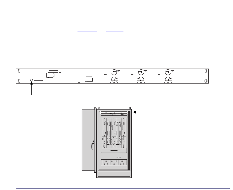
Understanding the Power Distribution Unit
IP-RN 8000 Installation & Commissioning Guide 27
Understanding the Power Distribution Unit
The Power Distribution Unit (PDU) contains control switches and circuit breakers that control power flow
through the IP-RN 8000. See Figure 14 and Table 15.
The PDU is pre-installed. The PDU is field-replaceable. Replacing the PDU is service disrupting.
For information about power the node on, see Powering the node on page 126.
Figure 14 Power Distribution Unit
Power Distribution Unit
Main Power
CHAS HEAT FANS USR2
ALRM USR1
HXCH
Main Power Status (LED)

Chapter 1 ● Introducing the IP-Radio Node 8000
28 Release 2.0, 910056 Rev01d
Table 15 Power Distribution Unit faceplate components
Component Faceplate
label Description
Main Power Main Power Switch left to turn on power flow to the IP-RN 8000.
Switch right to turn off power flow to the IP-RN 8000.
Main power status
LED
Main Power
Status
Lights green when Main Power switch is flipped to the left and a
power supply is delivering power.
Chassis CHAS Switch left to turn on power to the module enclosure and all installed
modules.
Switch right to turn off power flow to the module enclosure and all
installed modules.
Heat exchanger HXCH Switch left to turn on power flow to the front-door heat exchanger.
Switch right to turn off power flow to the front-door heat exchanger.
Alarms ALRM Switch left to turn on power flow to the Alarm Unit and to the Heat
Exchanger controller.
Switch right to turn off power flow to the Alarm Unit and to the Heat
Exchanger controller..
USR1 Reserved for future use.
USR2
Heater HEAT Reserved for future use.
Fan FANS Switch left to turn on power flow to the Fan Unit.
Switch right to turn off power flow to the Fan Unit.
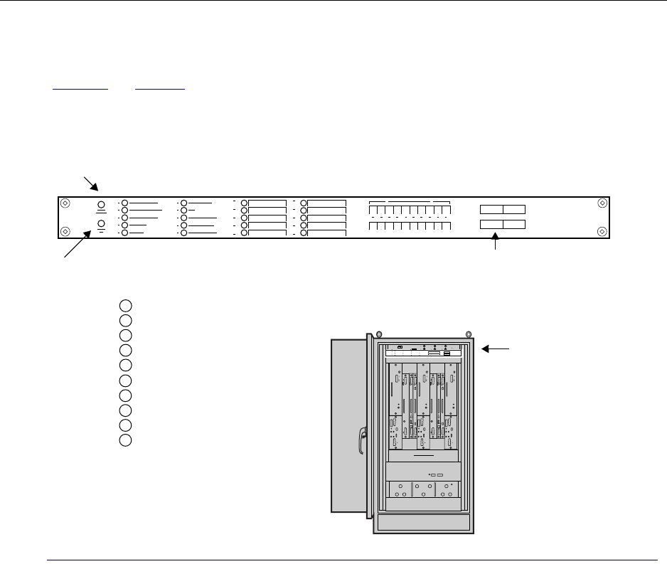
Understanding the Alarm Unit
IP-RN 8000 Installation & Commissioning Guide 29
Understanding the Alarm Unit
The Alarm Unit provides LEDs for all alarm circuits and switches for enabling and disabling them. See
Figure 15 and Table 16.
The Alarm Unit is pre-installed. The Alarm Unit is field-replaceable. Replacing the Alarm Unit is service
disrupting.
Figure 15 The Alarm Unit
Alarm Unit
Alarm
summary
PRIMARY CABINET
EXPANSION CABINET
BATTERY CABINET
HIGH TEMP
LOW TEMP
TECH-ON-SITE
FAN
HEAT EXCHANGER
POWER SUPPLY
DOOR/INTRUSION
6
7
8
9
10
1
2
3
4
5
Alarm
test
10 Standard 10 External alarm
10 External
alarm LEDs
alarm LEDs
input terminals
20 on/off switches

Chapter 1 ● Introducing the IP-Radio Node 8000
30 Release 2.0, 910056 Rev01d
Table 16 Alarm Unit faceplate components
Component Description
LEDs
See Understanding
LEDs on page 37
Alarm summary When any alarm LED turns RED, this LED changes from green
to red. If this LED is green, it means all 20 alarm LEDs are
green
10 Standard LEDs 1 PRIMARY CABINET Reserved for future use.
2 EXPANSION CABINET Reserved for future use.
3 BATTERY CABINET Reserved for future use.
4 HIGH TEMP Lights red when the internal
temperature exceeds 90 degrees
F.
5 LOW TEMP Lights red when the internal
temperature falls below 50
degrees F.
6 TECH-ON-SITE Lights green under normal
circumstances. Authorized
technicians should pull the
shaft forward to light the LED
red and suppress door intrusion
alarms.
• See Understanding the
tech-on-site switch on
page 36.
• See Opening the door on
page 198.
7 FAN Lights red when an alarm
occurs in the Fan Unit.
8 HEAT EXCHANGER Lights red when an alarm
occurs in the heat exchanger.
9 POWER SUPPLY Reserved for future use.
10 DOOR/INTRUSION Lights red when the front door
is open and the tech-on-site
switch is not pulled.
• See Understanding the
tech-on-site switch on
page 36.
• See Opening the door on
page 198.
10 external alarm
LEDs
These LEDs correspond to the 10 external alarm circuits that
are optionally wired to the 10 alarm input terminals. They light
green to indicate a non-alarm condition, red to indicate an alarm
condition.
Alarm test Press this button to tests the alarm unit. When pressed, all alarm LEDs light up red.
10 external alarm input terminals You can optionally attach 10 external alarm circuits to these
terminals.
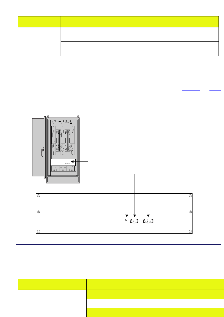
Understanding the Fan Unit
IP-RN 8000 Installation & Commissioning Guide 31
Understanding the Fan Unit
The Fan Unit moves air vertically through the chassis from the bottom to the top. See Figure 16 and Table
17.
The Fan Unit is pre-installed. The Fan Unit is field-replaceable. Replacing the Fan Unit is service disrupting.
Figure 16 Fan Unit
20 on/off switches Switches 1-10 turn on and off the standard alarms. Turned off alarm circuits report no
alarm status on LEDs.
Switches 11-20 turn on and off the 10 external alarms circuits. Turned off alarm circuits
report no alarm status on LEDs.
Table 17 Fan Unit faceplate components
Component Description
Fault LED Lights when a hardware fault is detected
Alarm cable Connects the Fan Unit to alarm system
Power cable Provides power to the Fan Unit.
Table 16 Alarm Unit faceplate components (continued)
Component Description
Fan unit
Power cable
Alarm cable
Fault LED
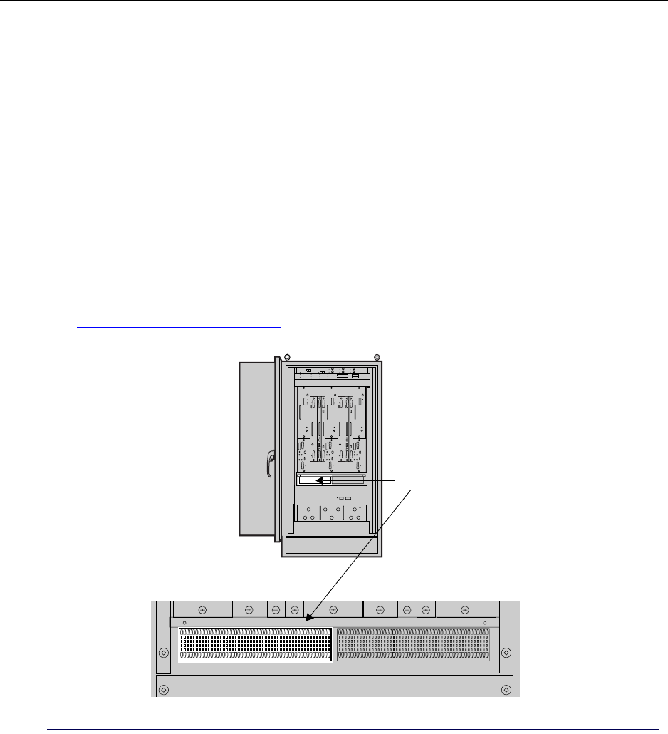
Chapter 1 ● Introducing the IP-Radio Node 8000
32 Release 2.0, 910056 Rev01d
Understanding the backhaul punch block and switch
Backhaul links connect the IP-RN 8000 to an IP-RNC 8500 and carry user traffic and management traffic.
There are two components to the backhaul system on the IP-RN 8000:
• Backhaul punch block — a wiring punch block used to physically connect T1/E1 or Ethernet links to
the IP-RN 8000
• Backhaul switch — an internal switch module that provides surge protection and connects the backhaul
punch block (and backhaul links) to the primary and optional redundant BIO/SC modules.
For more information, see Understanding the backhaul switch on page 33.
Understanding the backhaul punch block
The backhaul punch block is a standard type 66-block and provides hardware for connecting T1/E1 or
Ethernet lines for the backhaul network. The backhaul punch block is behind an access panel on the chassis
front that covers both the backhaul punch block and the alarm punch block.
See Chapter 5, Connecting the backhaul.
Figure 17 Backhaul punch block
Backhaul punch block
Understanding surge protection and grounding
IP-RN 8000 Installation & Commissioning Guide 33
Understanding the backhaul switch
The backhaul switch is pre-installed. The backhaul switch is field-replaceable. Replacing the backhaul
switch is service disrupting.
The backhaul switch is inside the cabinet and is not visible. It performs two important functions:
• Secondary surge protection
The IP-RN 8000 is protected from system transients on the backhaul caused by lightning and power
cross conditions.
• T1/E1 backhauls are switched and connected with the BIO/SC that is currently active.
For example, if your backhaul is a single T1 and you have a redundant IP-RN 8000 (with two Digital
Module Kits), you only need to provision a single T1 and wire it to the backhaul punch block. If the
redundant Digital Module Kit become active, the backhaul switch switches the T1 from the primary to
the redundant Digital Module Kit.
Ethernets are not switched. If you are deploying an Ethernet backhaul and you have a redundant
IP-RN 8000 (with two Digital Module Kits), you must provision and connect two Ethernets to the
backhaul punch block. One Ethernet is used as the backhaul by the primary Digital Module Kit and the
other Ethernet is used by the redundant Digital Module Kit.
Understanding surge protection and grounding
The IP-RN 8000 has multiple connections for attachment to the site’s grounding infrastructure. The
IP-RN 8000 has a secondary surge protection system for additional protection against lightning strikes
beyond the protection provided by a required primary external surge suppression system. A primary surge
protection system must be designed by qualified personnel for each site and must be installed accordingly to
prevent equipment damage and to minimize danger to nearby persons during lightning strikes.
Understanding the secondary surge protection system
The secondary surge protection system consists of surge suppressors for each antenna and surge suppressors
for the T1/E1 backhaul links that are electrically connected to the lighting ground coil. (For information
about the lightning ground coil, see Figure 3.) The lightning ground coil must be connected to an external
earth ground infrastructure.
The secondary surge protection system is designed to supplement a required external primary surge
protection system. Both must be in place to protect equipment and persons against lightning strikes traveling
down the cell tower along the RF and GPS antennas to the IP-RN 8000. Any surge that passes the required
external primary surge protection system is expected to take the following path to the earth ground
infrastructure:
• From the RF and GPS antennas through the surge suppressors onto the surge protection bar
• From the surge protection bar to the directly connected lead to the lightening ground coil
• From the lightning ground coil to the required external earth ground infrastructure
WARNING
Installation of a primary surge protection system and proper
grounding of the IP-RN 8000 according to all relevant codes and
requirements is necessary to avoid potential damage to the
equipment and to minimize danger persons near the equipment
during surges. Lightning protection design must be performed by
qualified personnel for each IP-RN 8000 installation.
Chapter 1 ● Introducing the IP-Radio Node 8000
34 Release 2.0, 910056 Rev01d
Understanding grounding requirements
Connection of the cabinet ground wire and the lightening ground wire to external earth ground systems that
meet all relevant codes and requirements is required.
Beyond the lightning ground wire and the cabinet ground wire, the following additional and optional ground
connections are available and may be utilized as required and appropriate at each site:
• Three pairs of dual lug holes with 1/4-20 threads. See Figure 3 on page 5 and Figure 4 on page 7,
• A third wire ground connected at the power terminal to provide a grounded link to an external power
cabinet.
Understanding external connections
During installation, you must connect the IP-RN 8000 to a range of external cables. Procedures for making
these cable connections are spread throughout this book. For an overview of the complete installation
procedure, see Chapter 2, Installation process.
Table 18 lists all connections that must be made and provides additional information.
WARNING
Grounding must be performed according to all relevant electrical
codes and requirements. The site planner must review grounding
requirements and determine the grounding plan accordingly.
Failure to provide adequate grounding can result in damage to
equipment and danger to personnel.
Table 18 IP-RN 8000 cable connections
Cable Description
Power cable External input ranging from 24 V DC to 29 V DC, 27 V DC nominal at the
cabinet power terminal
See Table 28 on page 193 for power specifications.
Ground connections Provides grounding for safety and equipment protection.
A main ground is required.
Additional optional grounding connections can also be installed.
See Understanding surge protection and grounding on page 33
See Table 29 on page 193 for grounding specifications.
RF antenna cables There are two basic antenna configurations per sector.
• The main receive (RX0) and the transmit (TX) can be combined on a
single antenna cable and the diversity receive (RX1) can be on a second
antenna cable
• The main receive, the transmit, and the diversity receive can be on
separate cables.
Antenna cables feed into the IP-RN 8000 through the Rox System cabinet
seal and must be connected internally to RF surge suppressors.
See Table 32 on page 194 for cable specifications.

Understanding external connections
IP-RN 8000 Installation & Commissioning Guide 35
Global Positioning System (GPS)
antenna cables
The Global Positioning System (GPS) provides the IP-RN 8000 with an
accurate clock source to synchronize network functions.
Two GPS antennas are required for redundancy and service continuity; if you
are installing a non-redundant system, only a single GPS antenna is required.
The far end of the GPS cable(s) typically use an “N-type” connector,
although other options are available.
The GPS antenna cables feed into the IP-RN 8000 through the Rox System
cabinet seal and must be connected internally to GPS surge suppressors.
See Table 32 on page 194 for cable specifications.
Backhaul connections Connect the IP-RN 8000 to the IP-RNC 8500 through a backhaul network.
Carry user data (AT to Internet) and management data between the
IP-RN 8000 to the IP-RNC 8500
Can install one, two, three, or four T1/E1 backhaul connections or one or two
10/100 Mbit/sec Ethernet backhaul connections as appropriate for the
deployment’s bandwidth and connectivity needs. the T1/E1 backhaul links
are used simultaneously providing all combined bandwidth; only a single
Ethernet backhaul link is used at a time, depending on which BIO/SC
module is active on a redundant system.
See Table 30 on page 193 for backhaul specifications.
Antenna Interface Unit (AIU) cables There are two antenna configurations that correspond to two versions of the
Antenna Interface Unit (AIU): the 6-port AIU and the 9-port AIU. This
installation guide provides procedures for installation of the 6-port AIU. In
this configuration, each radio sector has two antenna cables. One cable
carries one transmit and one receive signal. The other cable carries the
diversity receive signal that leads to a second antenna. With the 9-port AIU,
each sector has three antenna cables, two for receive and one for transmit.
Terminal cable for CLI access A COM port on a laptop PC is connected to the female DB-9 craft interface
on the active BIO/SC module to provide terminal access to the node.
Terminal access is required to complete the commissioning of the node.For
information on the DB-9 pin-out, see Table 35 on page 196.
Ethernet cable for software update at
the site
A craft Ethernet port on the BIO/SC module allows a technician to use FTP
to transfer node software releases from a laptop to the node. IP
configurations on the laptop and the Ethernet port must be made first.
Table 18 IP-RN 8000 cable connections (continued)
Cable Description
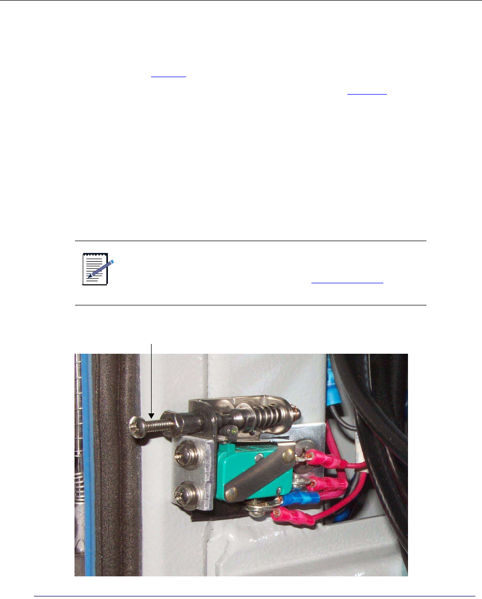
Chapter 1 ● Introducing the IP-Radio Node 8000
36 Release 2.0, 910056 Rev01d
Understanding the tech-on-site switch
The tech-on-site switch is a security feature that enables detection of unauthorized entry into the cabinet
through the door. The switch is located at the lower left of the front side of the cabinet and is only visible
when the door is open. See Figure 2.
The state of the switch is determined by the position of the main shaft. See Figure 18. The main shaft has
three positions:
• Normal — The shaft is spring loaded to take this position when the door opens causing the Tech-on-site
LED to light green.
In this position, opening the door triggers a Door/intrusion alarm. The Door/intrusion LED lights red
and the alarm is reported through software to the AirVista management system.
• Pulled forward— Technicians must pull the shaft of the switch forward to set the switch to this position,
which lights the Tech-on-site LED red and suppresses Door/intrusion alarms.
This position indicates an authorized technician has the door open. The Tech-on-site alarm LED lights
red and the Door/intrusion alarm is disabled and its LED lights green.
Figure 18 The tech-on-site switch
NOTE
Whenever an authorized technician opens the door, they must
pull the shaft of the switch forward into the tech-on-site position
to disable the Door/intrusion alarm. See Opening the door on
page 198
Main shaft

Understanding LEDs
IP-RN 8000 Installation & Commissioning Guide 37
Understanding LEDs
LEDs (light emitting diodes) on the faceplates of modules and units provide status information.
LEDs can take three states:
• Unlit — Indicates the LED or corresponding component is turned off
• Green — Indicates normal operation (or TRUE)
• Red — Indicates a condition that may require attention (or FALSE).
The states of LEDs are documented in relevant sections of this chapter.
The current status of LEDs is remotely available through the AirVista network management system.
Understanding cabinet air flow
Temperature is maintained in the cabinet using a heat exchanger in the front door and a fan unit in the
cabinet. There are two loops of air flow:
• The ambient loop provides air to the heat exchanger at ambient (external) temperature.
• The closed internal loop moves air through the inside of the cabinet.
The heat exchanger controls the temperature of the closed internal loop.
The heat exchanger is pre-installed. The heat exchanger is field-replaceable. Replacing the heat exchanger is
not service disrupting.
See Figure 19.
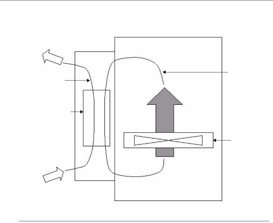
Chapter 1 ● Introducing the IP-Radio Node 8000
38 Release 2.0, 910056 Rev01d
Figure 19 Two loops of air flow for temperature control
Cabinet side view with the front door closed
Front door
Cabinet
Heat exchanger
Fan
Internal closed
air loop
Ambient loop

IP-RN 8000 Installation & Commissioning Guide 39
Chapter 2
Installation process
About this chapter
This chapter explains installation and commissioning and provides the process for installing the
IP-RN 8000. This chapter contains the following section.
•Understanding installation and commissioning on page 40
•Understanding the installation process on page 40

Chapter 2 ● Installation process
40 Release 2.0, 910056 Rev01d
Understanding installation and commissioning
This book explains how to physically install an IP-RN 8000 and how to commission it.
• Installation covers all physical tasks, such as attaching the cabinet to the concrete pad, inserting
modules, connecting power, connecting antennas, and so forth.
Installation is performed first. See Understanding the installation process on page 40.
•Commissioning covers all configuration and testing that must be performed by a technician at the site.
Commissioning is performed after installation is complete.
Commissioning is performed second. See Understanding the commissioning process on page 128.
Understanding the installation process
This process explains the steps to follow when installing the IP-RN 8000. Each step consists of one or more
procedures that must be performed in order and to completion before proceeding with the next step.
1. Planning and constructing the site
The site planner or installation manager must read the Airvana Cell Site Planning Guide and plan and
construct the site accordingly, ensuring that all site requirements are met. Site planning and construction
must be completed before installation starts.
2. Preparing for the installation
Before installation, you must read and understand all safety warnings and recommendations, and
understand IP-RN 8000 GR-1089 electrostatic discharge compliance and warnings.
See Understanding alternative installation on page 41.
See Chapter 3, Before you install.
3. Installing the cabinet
Plan the installation, prepare the cabinet, place and anchor the cabinet on the concrete pad, install power
and ground conduit as appropriate for you site, and connect power and ground.
See Chapter 4, Understanding the cabinet installation process on page 50.
4. Connecting the backhaul
Thread the backhaul cables through the cabinet and wire them into the backhaul punch block.
See Chapter 5, Understanding the backhaul installation process on page 74
5. Installing the antennas
Install the Rox System cabinet seal and connect all RF and GPS antennas.
See Chapter 6, Understanding the antenna installation process on page 86
6. Installing the modules
Install all modules into the cabinet.
See Chapter 7, Understanding the module installation process on page 104.
7. Powering on the IP-RN 8000
Power on the IP-RN 8000.
See Chapter 8, Powering the node on page 126.
The installation process is complete. You are now ready to continue with commissioning the
IP-RN 8000. Go to Chapter 9, Understanding the commissioning process on page 128

Understanding alternative installation
IP-RN 8000 Installation & Commissioning Guide 41
Understanding alternative installation
The order of events in the installation process are flexible to some degree. For example:
• You can install the modules before connecting the antennas
• You can install the antennas before the backhaul links.
CAUTION
If you install antennas before the modules, power spikes could
damage the modules.

Chapter 2 ● Installation process
42 Release 2.0, 910056 Rev01d

IP-RN 8000 Installation & Commissioning Guide 43
Chapter 3
Before you install
About this chapter
This chapter explains steps to take, warnings to follow, and notices to read, before installation. This
chapter contains the following sections:
•Site planning and construction on page 44
•Planning the network on page 44
•Receiving all shipping and materials on page 44
•Electro static discharge and GR-1089 compliance on page 44
•Safety Recommendations and Warnings on page 45
•Notices on page 47

Chapter 3 ● Before you install
44 Release 2.0, 910056 Rev01d
Site planning and construction
Before installation, the site planner or installation manager must read the Airvana Cell Site Planning Guide.
This guide explains all site requirements that must be met for a successful installation. These requirements
include the following:
• Site construction, including the concrete pad or equivalent pad or floor that meets loading requirements
• Power supply
• Grounding infrastructure
• Backhaul link(s)
• Power and backhaul conduits
• Antenna configuration
• Global Positioning System (GPS) antenna(s)
• Primary external lightening/surge protection equipment
Planning the network
The network has to be planned. Network planning includes radio network planning, backhaul infrastructure
planning, and IP address/network planning.
Receiving all shipping and materials
All expected crates and packages associated with the installation must be received at the installation site.
• All shipping containers must be present and accounted for.
• All shipping containers must be undamaged
Electro static discharge and GR-1089 compliance
The IP-RN 8000 complies with GR-1089 System Level Electrostatic Discharge with the door closed.
When the front door is open, an electro static discharge wrist strap must be worn and connected to the ESD
jack on the Antenna Interface Unit prevent potential service disruption.
WRIST
STRAP
Wear an ESD strap () and connect the strap to the ESD jack in the
Antenna Interface Unit whenever the front door is open. See
Understanding the Antenna Interface Unit module on page 17.

Safety Recommendations and Warnings
IP-RN 8000 Installation & Commissioning Guide 45
Safety Recommendations and Warnings
The guidelines that follow help to ensure your safety and to protect the IP-RN 8000. These guidelines may
not address all potentially hazardous situations in your working environment, so be alert, and exercise good
judgement at all times.
• Keep the chassis area clear and dust-free before, during, and after installation.
• Keep tools away from walk areas where people could fall over them.
• Do not wear loose clothing or jewelry, such as rings, bracelets, or chains, which may become caught in
the chassis.
• Wear safety glasses if you are working under any conditions that may be hazardous to your eyes.
• Do not perform any actions that create a potential hazard to people or make the equipment unsafe.
• Never attempt to lift an object that is too heavy for one person to handle.
Radio frequency radiation exposure limits
Upon installation, this product is required to comply with the requirements of Federal Communications
Commission 47CFR 1.1310, Radio frequency radiation exposure limits. Care must be taken by the installer
to insure that the antenna chosen along with its installation position and orientation does not violate these
limits.
Lithium battery warning
The BIO/SC module contains a lithium battery to which the following warning applies:
Caution: there is a danger of explosion if the battery is incorrectly replaced. Replace the batter only with the
same type or with an equivalent type that is recommended by the manufacturer. Discard used batteries
according to the manufacturer’s instructions.
The same warning in French:
Attention: Il y a danger d’explosion s’il y a remplacement incorrect de la batterie. Remplacer uniquement
avec une batterie du même type ou d’un type recommandé par le constructeur. Mettre au rébut les batteries
usagées conformément aux instructions du fabricant.
Maintaining Safety With Electricity
Before working on a chassis or working near power supplies, unplug the power cords on an AC-powered
system. On a DC-powered system, disconnect the power at the circuit breakers. Follow these guidelines
when working on equipment powered by electricity:
• Locate the emergency power-off switch for the area in which you are working. If an electrical accident
occurs, you can quickly turn off the power.
• Do not work alone if potentially hazardous conditions exist anywhere in your work space.
• Never assume that power is disconnected from a circuit: always check the circuit.
• Carefully look for possible hazards in your work area, such as moist floors, ungrounded power
extension cords, or missing safety grounds.
• If an electrical accident occurs:
— Use caution. Do not let yourself become a victim.
— Disconnect power from the system.
— If possible, send another person to get medical aid. Otherwise, assess the condition of the victim
then call for help.

Chapter 3 ● Before you install
46 Release 2.0, 910056 Rev01d
Install the IP-RN 8000 following local, national, or international electrical codes:
• United States — National Fire Protection Association (NFPA70), United States National Electrical
Code.
• Canada — Canadian Electrical Code, Part 1, CSA C22.1.
• Other countries — International Electromechanical Commission (IEC) 364, Part 1 through Part 7.
Warning Definition
Product Disposal
Ultimate disposal of this product should be handled according to all national laws and regulations.
Lightning Activity Warning
Do not work on the system or connect or disconnect cables during periods of lightning activity.
Jewelry Removal Warning
Before working on equipment that is connected to power lines, remove jewelry (including rings, necklaces,
and watches). Metal objects will heat up when connected to power and ground and can cause serious burns
or weld the metal object to the terminals.
Power Supply Warning
Do not touch the power supply when the power cord is connected. Line voltages are present within the
power supply even when the power switch is off and the power cord is connected.
Power Supply Disconnection Warning
Before working on a chassis or working near power supplies, unplug the power cord on AC units;
disconnect the power at the circuit breaker on DC units.
Power Disconnection Warning
Before working on a system that has an On/Off switch, turn OFF the power and unplug the power cord.
WARNING
Warning means danger. You are in a situation that could cause
bodily injury or death. Before you work on any equipment, be
aware of the hazards involved with electrical circuitry and be
familiar with standard practices for preventing accidents.

Notices
IP-RN 8000 Installation & Commissioning Guide 47
Grounded Equipment Warning
This equipment is intended to be grounded. Ensure that the IP-RN 8000 is connected to earth ground during
normal use.
Installation Warning
Read the installation instructions before you connect the system to its power source.
Notices
Part-68 Notice
This equipment complies with Part 68 of the FCC rules and the requirements adopted by the ACTA. On the
right hand side of the Backhaul Switch Panel of this equipment is a label that contains, among other
information, a product identifier in the format US: ARVDENANRN8000. If requested, this number must be
provided to the telephone company.
If this equipment causes harm to the telephone network, the telephone company will notify you in advance
that temporary discontinuance of service might be required. If advance notice is not practical, the telephone
company notifies you as soon as possible. Also, you are advised of your right to file a complaint with the
FCC if you believe it is necessary.
The telephone company may make changes in its facilities, equipment, operations, or procedures that could
affect the operation of the equipment. If this happens, the telephone company will provide advance notice so
you can make the necessary modifications to maintain uninterrupted service.
If trouble is experienced with this equipment, please contact Airvana at 1-866-344-7437 for repair and
warranty information. If the equipment is causing harm to the telephone network, the telephone company
may request that you disconnect the equipment from the network until the problem is resolved.
This equipment uses Uniform Service Order Code (USOC) jack number RJ48H.

Chapter 3 ● Before you install
48 Release 2.0, 910056 Rev01d

IP-RN 8000 Installation & Commissioning Guide 49
Chapter 4
Installing the cabinet, power, and ground
About this chapter
This chapter explains in the procedures for installing the chassis and contains the following
sections:
•Understanding the cabinet installation process on page 50
•Understanding outdoor installation on page 51
•Understanding indoor installation on page 52
•Planning conduit and grounding installation on page 53
•Unpacking the cabinet from its shipping container on page 54
•Removing access panels on page 56
•Unbolting the cabinet from its palette on page 57
•Placing the cabinet on the concrete pad on page 58
•Bolting the cabinet in place on page 62
•Re-installing the left side access panel on page 63
•Routing power and backhaul cables into cabinet and closing right side access panel on page 64
•Connecting the power supply on page 65
•Understanding the cabinet installation process on page 50
•Testing primary power on page 69

Chapter 4 ● Installing the cabinet, power, and ground
50 Release 2.0, 910056 Rev01d
Understanding the cabinet installation process
This process explains all steps and procedures to follow when installing the IP-RN 8000 cabinet at the cell
site, connecting the main ground rods, and connecting power. Two people are required for cabinet
installation.
1. Understanding outdoor and indoor installation
Read these sections to understand outdoor and indoor installation requirements.
• See Understanding outdoor installation on page 51.
• See Understanding indoor installation on page 52.
2. Planning conduit and grounding installation order
Plan the order in which you install conduit and connect the grounding wires.
See Planning conduit and grounding installation on page 53
3. Preparing for cabinet installation
Unpack the cabinet, remove two access panels, and unbolt the cabinet from its shipping palette.
a. See Unpacking the cabinet from its shipping container on page 54.
b. See Removing access panels on page 56.
c. See Unbolting the cabinet from its palette on page 57.
4. Anchoring the cabinet
Place the cabinet onto its concrete pad, bolt it in place, and reinstall the left side cable access panel.
a. See Placing the cabinet on the concrete pad on page 58.
b. See Bolting the cabinet in place on page 62.
c. See Re-installing the left side access panel on page 63
5. Removing the power terminal access panel
See Removing the power terminal access panel on page 204.
6. Installing power and backhaul cables/conduit and closing right side access panel
This section provides general instructions for routing power and backhaul cables into the cabinet and
installing external conduit. Cable and conduit installation methods and materials vary from site to site
and must be performed according to all local codes and practises.
See Routing power and backhaul cables into cabinet and closing right side access panel on page 64
7. Connecting power and grounding
Connect site power to the IP-RN 8000, grounding the IP-RN 8000, and testing power flow to the
IP-RN 8000 and to its internal components.
a. See Connecting the power supply on page 65
b. See Grounding the cabinet on page 67
c. See Testing primary power on page 69
This process is complete. You must connect the backhaul link(s). Go to Understanding the backhaul
installation process on page 74.

Understanding outdoor installation
IP-RN 8000 Installation & Commissioning Guide 51
Understanding outdoor installation
This chapter provides a detailed process for outdoor cabinet installation. Additional detailed site planning
and construction requirements are provided in the Airvana Cell Site Planning Guide. Also adhere to the
following when planning the site.
Mounting pad
The procedures in this chapter refer to constructing a concrete pad onto which the cabinet is installed.
Concrete is recommended, but you can also install the cabinet onto other suitable pads or frameworks. For
example, you can install onto steel rails. You must ensure the mounting pad/structure meets all loading and
seismic requirements.
Airvana supplies a rubber insulation pad in the cabinet shipping crate that must be installed between the
mounting surface and the cabinet.
Loading
The mounting pad/structure must be able to support the load of the cabinet when fully populated with all
optional equipment. Loading is a function of the weight and the footprint dimensions.
• A fully populated cabinet weighs 630 pounds.
• The footprint dimensions are: width: 30.5 inches; depth 39 inches.
Lifting - overhead space
There must be sufficient space above the cabinet to lift it into place. The cabinet is 59.5 inches in height.
Once the cabinet is disconnected from its shipping palette, it can only be moved by attaching a sling to the
lifting hooks on the top and using a crane (or other lifting device capable of handling the cabinet’s unloaded
weight of 500 pounds). There must be sufficient headroom above the cabinet to attach a sling and a crane
and then to lift the cabinet into place. The sling must allow five feet between the crane hook and the cabinet
top. See Placing the cabinet on the concrete pad on page 58.
Earthquakes
The mounting surface onto which the cabinet is installed must able to withstand local earthquakes. The
surface must be constructed according to local earthquake codes to withstand seismic events of the local
seismic zone (seismic zone 1, 2, 3, or 4).
Mounting hardware
You must supply the mounting hardware:
• Four anchor bolts — 1/2 inch bolts that comply with the ASTM specification with a minimum
protrusion above the floor of 1 1/8 inches
• Four flat washers, lock washers, and nuts
Airvana supplies a cardboard template that indicates the position of the anchor bolts. This template is
included in the cabinet’s shipping crate.

Chapter 4 ● Installing the cabinet, power, and ground
52 Release 2.0, 910056 Rev01d
Understanding indoor installation
For indoor installation, you can follow the outdoor installation process, but you must adhere to the following
requirements.
Loading
The building and floor must be able to support the load of the cabinet when fully populated with all optional
equipment. The loading is a function of the weight and the footprint dimensions.
• A fully populated cabinet weighs about 630 pounds.
• The footprint dimensions are: width: 30.5 inches; depth 39: inches.
Lifting - overhead space
There must be sufficient space above the cabinet to lift it into place. The cabinet is 59.5 inches in height.
Once the cabinet is disconnected from its shipping palette, it can only be moved by attaching a sling to the
lifting hooks on the top and using a crane (or other lifting device capable of handling the cabinet’s unloaded
weight of 500 pounds). There must be sufficient headroom above the cabinet to attach a sling and a crane
and then to lift the cabinet into place. The sling must allow five feet between the crane hook and the cabinet
top. See Placing the cabinet on the concrete pad on page 58.
Earthquakes
The building/structure in which the cabinet is installed must able to withstand local earthquakes. The
building/structure must be constructed according to local earthquake codes to withstand seismic events of
the local seismic zone (seismic zone 1, 2, 3, or 4).
Mounting
You must supply the mounting hardware:
• Four anchor bolts — 1/2 inch bolts that comply with the ASTM specification with a minimum
protrusion above the floor of 1 1/8 inches
• Four flat washers, lock washers, and nuts
Airvana supplies a cardboard template that indicates the position of the anchor bolts. This template is
included in the cabinet’s shipping crate.
Planning conduit and grounding installation
IP-RN 8000 Installation & Commissioning Guide 53
Planning conduit and grounding installation
It is important to plan the order in which you install conduit and connect the grounding coils to prevent
difficulty.
The difficulty could arise when:
• Installing the second conduit after the first conduit is in place. The access panel could be difficult to
remove if inflexible conduit is already installed.
• Installing any conduit after the grounding coils are connected without slack. If the grounding coils are
installed without slack, it may be difficult to back the access panel away from the cabinet in order to
attach the conduit.
The installation process documented here assumes that you can install power cables and conduit and
backhaul cables and conduit at the same time. This only requires removing the access panel once. If you
need to install these items at different times, you might want to take the following steps:
• When you connect the grounding coils, run the wires straight out from the cabinet side for about one
foot to enable the access panel to be backed away from the cabinet later for conduit installation.
• When you install the first conduit, install a stub conduit for the second opening. Make sure the stub
conduit is plugged properly to seal the inside of the cabinet from damage from the environment. This
prevents the need to open the access panel later, which might requiring disassembling the first conduit.
NOTE
This installation process does not specify the type of conduit you
use or the manner of installation. The site planner must specify
all conduit according to local standards and codes.
CAUTION
Improper selection or installation of conduit may compromise the
EMI/RFI integrity of the system.
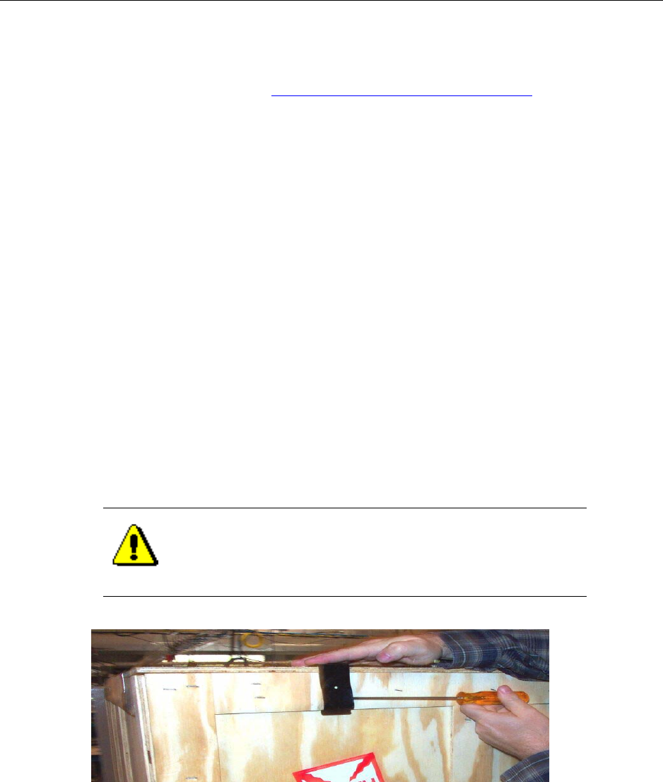
Chapter 4 ● Installing the cabinet, power, and ground
54 Release 2.0, 910056 Rev01d
Unpacking the cabinet from its shipping container
This procedure explains how to unpack the cabinet from its shipping container.
Be sure you have read and understood Understanding the cabinet installation process on page 50 before
continuing.
Requirements
• 5/8 inch open ended wrench
• Slotted screwdriver
Procedure
1. Familiarize yourself with the shipping crate.
The IP-RN 8000 is shipped as follows: it is bolted to a palette, covered with a plastic bag, and wooden
sides and a top are attached with metal snaps. Additional material may be shipped in boxes tucked
beneath the cabinet door.
2. Using a slotted screwdriver, remove the metal snaps that hold the wooden top of the shipping cabinet in
place.
To remove the snaps:
a. Insert the screwdriver behind the half of the snap that has a wedge shaped relief for it, and hold the
other half of the snap against the cabinet with your open hand.
b. Gently pry the snap away from the cabinet until it releases.
3. Lift the wooden top off.
CAUTION
Hold the snap as you pry it off. Otherwise, the snap may fly into
the air when it is pried off.
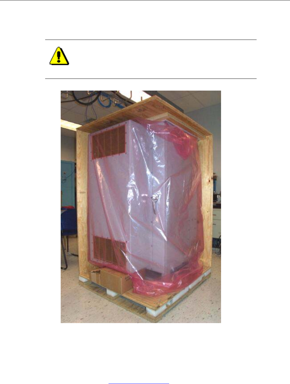
Unpacking the cabinet from its shipping container
IP-RN 8000 Installation & Commissioning Guide 55
4. Using the same procedure, carefully remove the snaps holding the shipping crate’s wooden sides in
place.
5. Remove the plastic bag covering the cabinet.
6. Remove any boxes that may have been tucked beneath the cabinet front door.
A cardboard template is tucked in the crate that can be used to locate the anchor bolts you embed in the
concrete pad when the pad is poured.
This procedure is complete. Go to Removing access panels on page 56
CAUTION
As you remove the snaps, the wooden sides will fall off. Hold the
sides in place as you remove the snaps.

Chapter 4 ● Installing the cabinet, power, and ground
56 Release 2.0, 910056 Rev01d
Removing access panels
This procedure explains how to remove the left-side access panel and to back the right side cable access
panel away from the cabinet. Be sure you have read and understood Understanding the cabinet installation
process on page 50 before continuing.
Requirements
• 5/32 inch, tamper-resistant hex driver
• 17 mm open ended wrench
Procedure
1. Locate the left side access panel. See Figure 3 on page 5.
2. Using a 5/32 inch, tamper-resistant hex driver, remove the 12 screws and rubber washers holding the left
side access panel in place, being careful not to let the access panel fall when the final screws are
removed.
3. Set aside the 12 access panel screws and washers.
The screws and washers will be required for re-installing the access panel after the cabinet is bolted to
the concrete installation pad.
4. Locate the right side cable access panel. See Figure 3 on page 5.
5. Remove the bubble wrap covers from the two grounding coils. See Figure 3 on page 5.
6. Uncoil about one foot of each grounding coil starting at the cabinet end of the coil.
Straightening out the cabinet end of the coils will enable the right side access panel to be backed away
from the cabinet.
7. Use an 17 mm open ended wrench to loosen the two nuts where the coils feed through the access panel.
Loosening these nuts enables the access panel to slide down the coils as it is backed away from the
cabinet.
8. Using a 5/32 inch, tamper-resistant hex driver, remove the 12 screws and rubber washers holding the
right side access panel in place.
9. Set aside the 12 access panel screws and washers.
The screws and washers will be required for re-installing the access panel after the cabinet is bolted to
the concrete installation pad.
10. Carefully pull the access panel away from the cabinet, feeding the straightened grounding coils through
their holes in the access panel.
This procedure is complete. Go to Unbolting the cabinet from its palette on page 57.
CAUTION
Access panels must be handled carefully. If they are bent they
may not form a proper seal with the cabinet when they are
re-installed. An intact seal on the inside edge of the access panel
is required to ensure external environmental conditions are sealed
out.
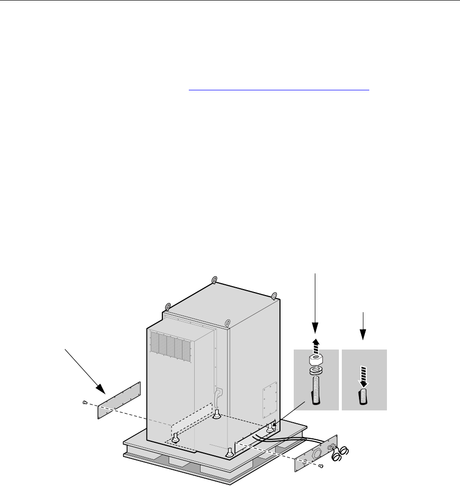
Unbolting the cabinet from its palette
IP-RN 8000 Installation & Commissioning Guide 57
Unbolting the cabinet from its palette
This procedure explains how to unbolt the cabinet from its shipping palette. At this point, the left side access
panel is removed and the right side access panel is backed away from the cabinet. You now have access to
the four bolts that attach the cabinet to the palette.
Be sure you have read and understood Understanding the cabinet installation process on page 50 before
continuing.
Requirements
• 5/8 inch open ended wrench
Procedure
1. Using a 5/8 inch open-end wrench, remove the four nuts, lock washers and washers that secure the
cabinet to the pallet.
Access the nuts through the side access panels you have just removed.
2. Set the four nuts, washers, and lock washers aside.
These may be used to bolt the cabinet to the concrete pad. You may also use other nuts and washers that
are appropriate for the type of anchor bolts you have embedded in the concrete pad.
Nut and washers removed
panel removed
Right side access panel
backed away
Bolt pressed down
Left side access

Chapter 4 ● Installing the cabinet, power, and ground
58 Release 2.0, 910056 Rev01d
3. Physically push down on each bolt forcing it out of the bottom of the pallet.
This procedure is complete. Go to Placing the cabinet on the concrete pad on page 58.
Placing the cabinet on the concrete pad
This procedure explains how to place the cabinet on its insulation pad and concrete pad or floor.
Be sure you have read and understood Understanding the cabinet installation process on page 50 before
continuing.
Requirements
• Insulation pad shipped with the IP-RN 8000
• Four eye bolts that were shipped with the IP-RN 8000 (used to lift the cabinet)
• Crane sufficient to safely lift the 500 pound IP-RN 8000
CAUTION
Do not open the door, or push on, or lean against the cabinet. The
cabinet cab can tip over and cause death, injury, and equipment
damage. Do not move the palette after removing the anchor bolts.
NOTE
This step requires two people to ensure safety and to protect
equipment from damage.
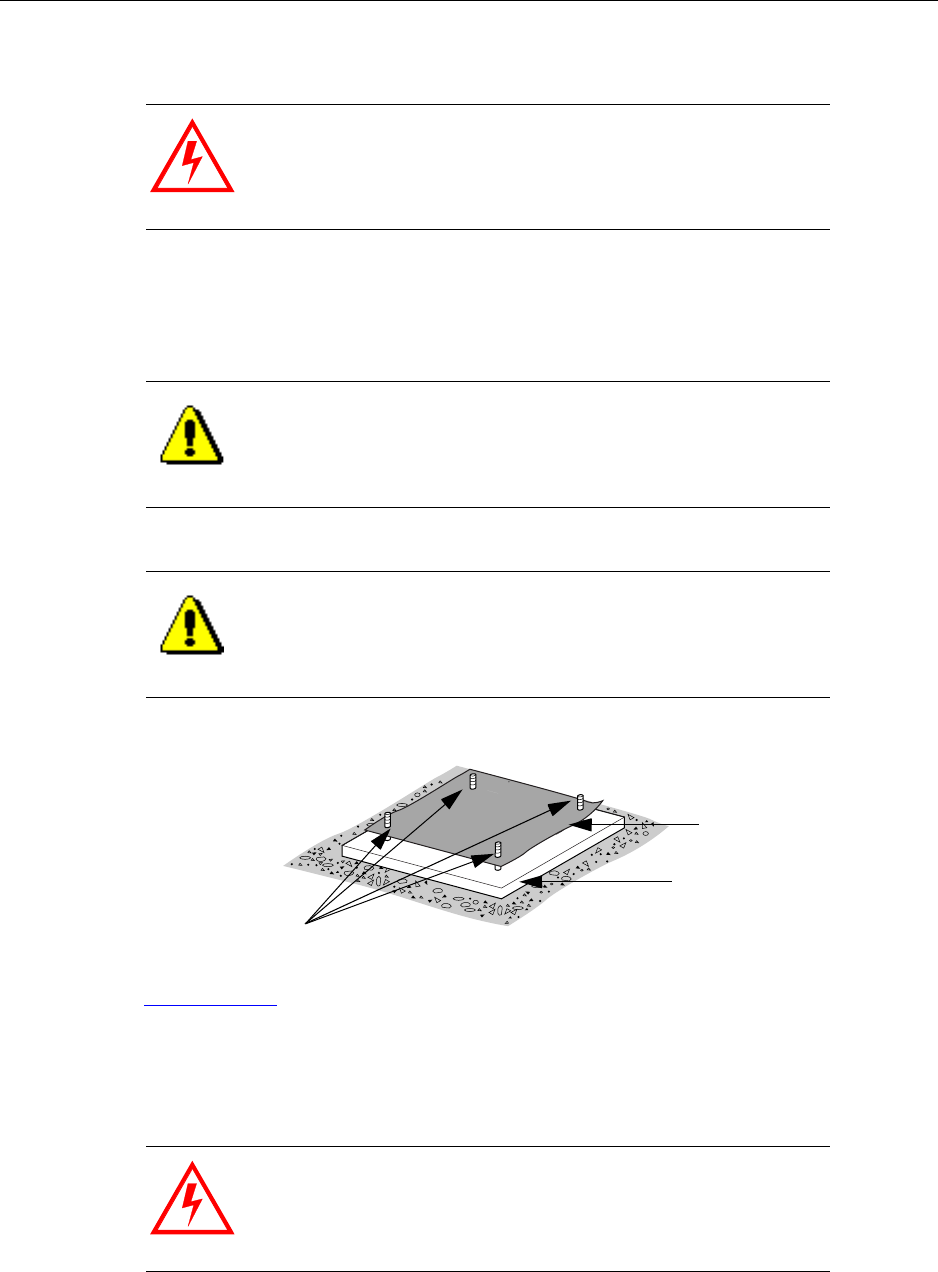
Placing the cabinet on the concrete pad
IP-RN 8000 Installation & Commissioning Guide 59
Procedure
1. Lay the insulation pad that was shipped with the IP-RN 8000 on the concrete pad.
Ensure the four bolts embedded in the concrete pad or floor stick up through the holes at the corners of
the insulation pad. Ensure the pad lays flat and is not wrinkled or folded.
2. Ensure the cabinet door is closed and latched.
See Closing the door on page 199.
3. Screw the four eye bolts into the top of the cabinet.
Ensure the eye bolts are screwed in snugly.
The eye bolts are shipped with the cabinet.
WARNING
The IP-RN 8000 is now disconnected from the palette. Do not
open the door, or push on or lean against the cabinet as it may tip
over causing equipment damage, injury, or death. Do not move
the palette.
CAUTION
Proper placement of this pad is essential to prevent corrosion.
CAUTION
The quality of the concrete must meet 3000-pound per square
inch (psi) concrete specifications and should be at least 8 inches
thick to achieve the design requirement for wind and seismic
loading.
WARNING
Failure to screw the eye bolts in all the way could cause them to
fall out during lifting and this could cause death, injury, or
equipment damage.
Rubber insulation
Concrete pad
Anchoring bolts
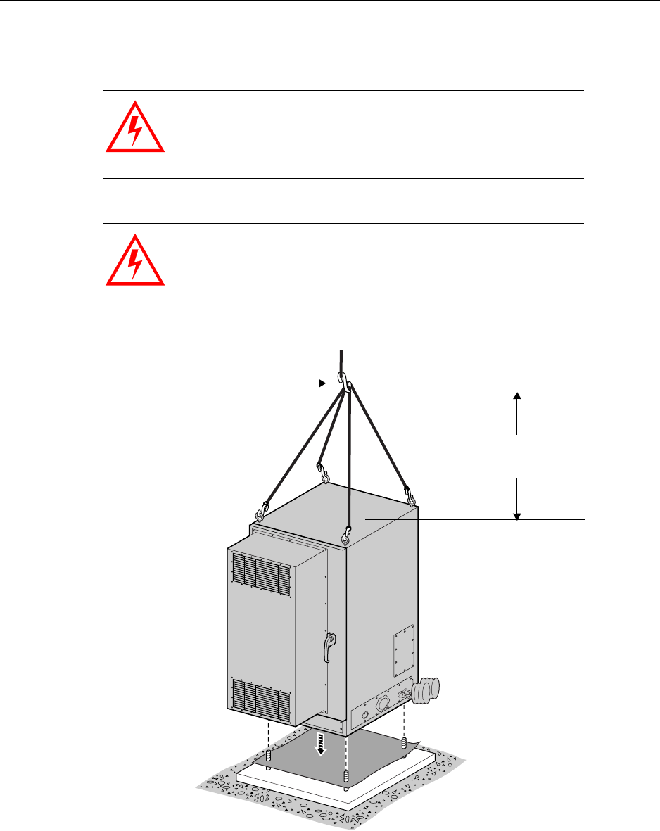
Chapter 4 ● Installing the cabinet, power, and ground
60 Release 2.0, 910056 Rev01d
4. Use the four lifting hooks on the top of the enclosure to attach the IP-RN 8000 to a crane or proper
lifting device.
WARNING
Use of improper lifting equipment can result in personal injury or
death and may result in damage to the IP-RN 8000.
WARNING
There must be a minimum of five feet clearance between the top
of the cabinet and the crane hook to ensure shear forces do not
bend and break the eye bolt hooks. Failure to provide this
clearance could result in the cabinet dropping from the crane
causing personal injury or death and equipment damage.
Five feet minimum
from crane hook to
top of cabinet
Crane hook
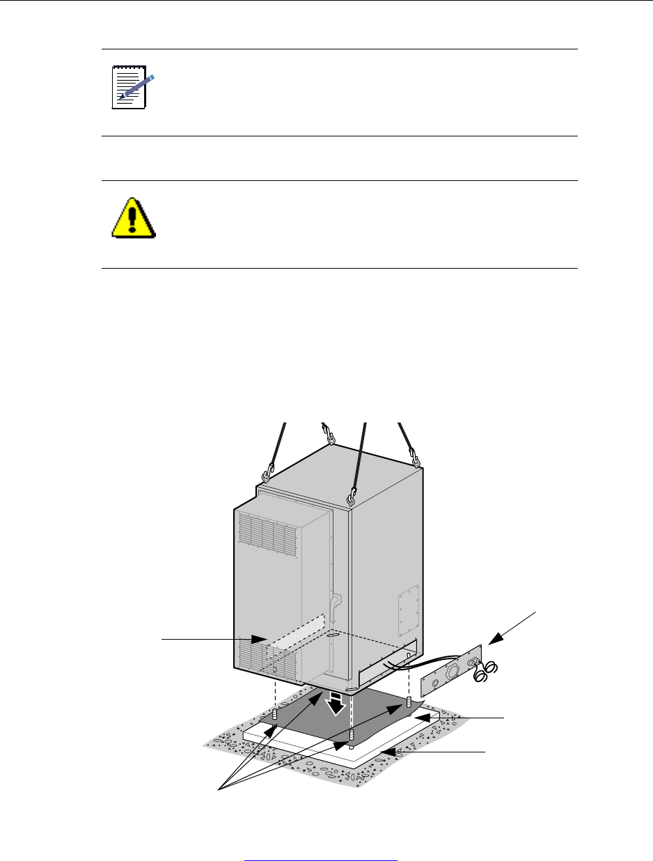
Placing the cabinet on the concrete pad
IP-RN 8000 Installation & Commissioning Guide 61
5. With one person operating the crane and another holding the access panel out of the way and aligning
the cabinet as the cabinet is lowered, lift the IP-RN 8000 off the pallet and lower it onto the concrete
pad, ensuring the following:
• The four corner bolts stick up through the four bolt holes in the base of the enclosure.
• No part of the IP-RN 8000 enclosure has direct contact with the concrete. The insulation pad
should be visible all the way around the cabinet.
This procedure is complete. Go to Bolting the cabinet in place on page 62.
NOTE
In the following steps, one person should operate the lift and the
other person should hold the backed away access panel up and
out of the way and help align the cabinet with the four anchor
bolts in the concrete pad as the cabinet is lowered into place.
CAUTION
When lowering the cabinet onto the pad, take special care not to
damage the threads on the anchor bolts. These four anchor bolts
are essential to a successful installation.
Rubber insulation
Concrete pad
Anchoring bolts
Left side access
panel removed
Right side access
panel backed away
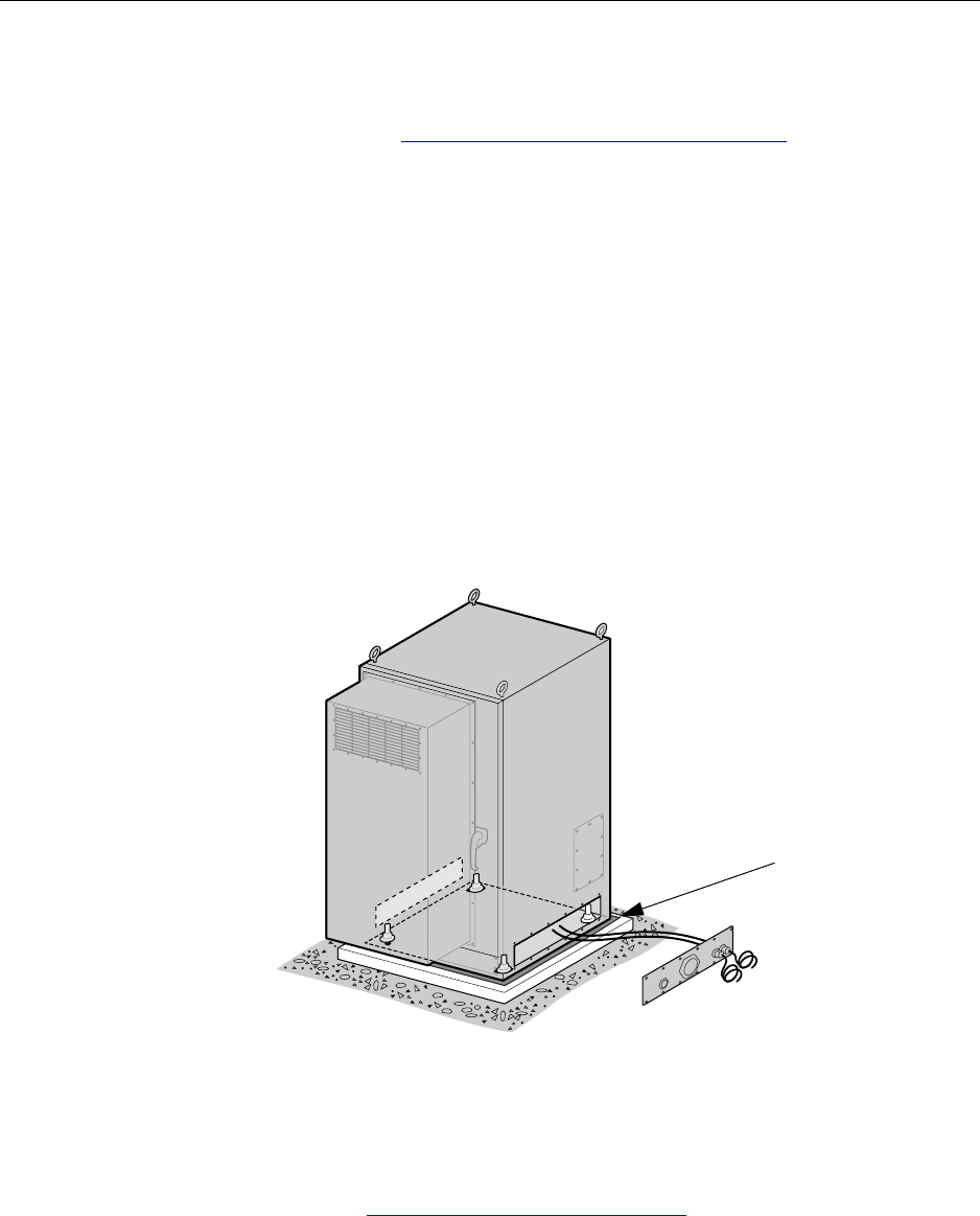
Chapter 4 ● Installing the cabinet, power, and ground
62 Release 2.0, 910056 Rev01d
Bolting the cabinet in place
This procedure explains how to bolt the cabinet onto the concrete insulation pad.
Be sure you have read and understood Understanding the cabinet installation process on page 50 before
continuing.
Requirements
• Open ended wrench of appropriate size for your anchor bolt nuts
• Four washers, lock washers, and nuts for the anchor bolts embedded in the concrete pad
These are not provided by Airvana but are specified by the site planner.
Procedure
1. Look through the removed left side access panel and the backed away right side access panel and find
the four anchoring bolts sticking up from the concrete pad through holes in the cabinet base.
2. Using the four washers, lock washers and nuts, thread a washer, lock washer and nut onto each anchor
bolt.
3. Use an appropriately sized open ended wrench to tighten the four nuts.
This procedure is complete. Go to Re-installing the left side access panel on page 63
Rubber insulation
pad visible from
all sides
Re-installing the left side access panel
IP-RN 8000 Installation & Commissioning Guide 63
Re-installing the left side access panel
This procedure explains how to re-install the left side access panel. Be sure you have read and
understood Understanding the cabinet installation process on page 50 before continuing.
Requirements
• 5/32 inch tamper-resistant hex driver
• Thread tapping set with 1/4-20 bit for 3/4 depth
Procedure
1. Retrieve the 12 tamper-proof screws and rubber washers that you set aside when removing the panel.
2. Ensure the left side access panel is undamaged:
Examine the inside edge of the access panel. The gasket on the inside edge must be intact to ensure a
proper seal.
3. Position the access panel and start all screws by hand. See Understanding access panels on page 9.
Thread the rubber sealing washer on the screw shank before inserting it in the access panel screw hole.
4. Use a torque wrench with a 5/32 inch tamper-resistant hex drive bit set to 18 inch-pounds to tighten all
screws evenly.
At this point, the cabinet is installed on the concrete pad and the left access panel is re-installed.
This procedure is complete. Go to Routing power and backhaul cables into cabinet and closing right side
access panel on page 64.
NOTE
The right side access panel will remain backed away from the
cabinet in order to install power and backhaul cables and conduit.
WARNING
Screws should be started by hand. It is possible to damage the
thread in the cabinet if you use a hand tool or a power tool.
Damaged threads must be repaired or the cabinet will be
improperly sealed and the IP-RN 8000 can be damaged. Use a
thread tapping set to fixed damaged threads. If the thread is
damaged beyond repair, contact Airvana.
WARNING
If access panels screws are not tightened with the correct torque,
water intrusion may occur causing equipment malfunction.
Chapter 4 ● Installing the cabinet, power, and ground
64 Release 2.0, 910056 Rev01d
Routing power and backhaul cables into cabinet and closing
right side access panel
At this point the cabinet is secured to its concrete pad, and the right side cable access panel is backed away
from the cabinet. This is an appropriate time to thread the power cable into the cabinet and install the power
conduit and to thread the backhaul cable into the cabinet and install its conduit according to your site
planner’s specifications. This procedure explains in general how to perform these steps, but the details of
conduit installation are dependent on your site planner’s specifications.
Be sure you have read and understood Understanding the cabinet installation process on page 50 before
continuing.
Requirements
Tools required depend on the particular grounding methods and materials specified by the site planner for
this particular site.
Procedure
1. Remove the power terminal access panel. See Removing the power terminal access panel on page 204.
2. Thread the power cable through its conduit and attach the power conduit to the power cable access port
on the right side access panel. To locate the power cable access port, see Right side view with the front
door open on page 5.
3. From the front of the cabinet, reach through the power terminal access panel area and grip the power
cable.
4. Pull enough power cable forward to the front of the cabinet so that you will be able to attach the cable to
the power terminal.
For information on the power terminal, see Understanding the cabinet font view on page 3.
NOTE
•If it is not possible to schedule technicians to install
power and backhaul cables at this time, you must
re-install the right side access panel to ensure the
cabinet is sealed. See Re-installing the right side
cable access panel on page 207.
•Later procedures assume the power and backhaul
cables are available inside the cabinet.
WARNING
Power supply must meet IP-RN 8000 specifications. See Power
specifications on page 193.

Connecting the power supply
IP-RN 8000 Installation & Commissioning Guide 65
5. Thread the backhaul cable through its conduit and attach the backhaul conduit to backhaul cable port on
the right side cable access panel. To locate the backhaul cable port, see Right side view with the front
door open on page 5.
6. Reach through the power terminal access panel area and grip the backhaul cable(s).
7. Pull five feet of backhaul cable(s) forward to the front of the cabinet.
8. Re-install the right side cable access panel. See Re-installing the right side cable access panel on
page 207.
This procedure is complete. Go to Connecting the power supply on page 65.
Connecting the power supply
This procedure explains how to connect the power wires to the power terminals.
You can optionally connect a third wire ground if your site planner specifies it. See Understanding surge
protection and grounding on page 33.
Be sure you have read and understood Understanding the cabinet installation process on page 50 before
continuing.
Requirements
• 3/16 inch hex wrench
NOTE
The backhaul cable could consist of one to four separate cables.
See Understanding the backhaul installation process on page 74
NOTE
This procedure assumes the power cables are already threaded
inside the cabinet. See Routing power and backhaul cables into
cabinet and closing right side access panel on page 64.
WARNING
Power supply must meet IP-RN 8000 specifications. See Power
specifications on page 193.
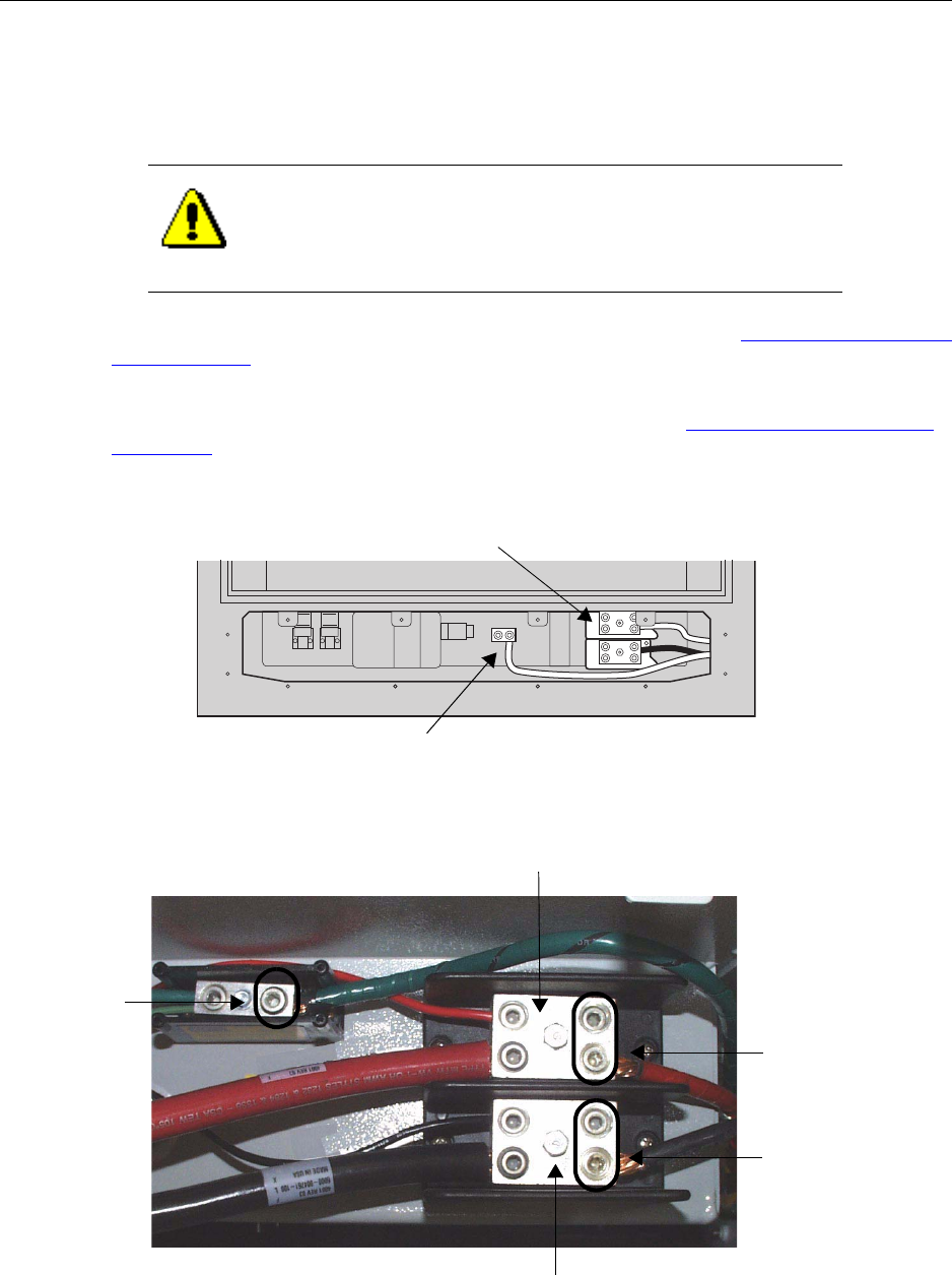
Chapter 4 ● Installing the cabinet, power, and ground
66 Release 2.0, 910056 Rev01d
Procedure
1. Open the main circuit breaker to disable power flow through the power cable. Break the circuit so that
there is no power on the power cable.
2. Flip all power switches on the power distribution unit (PDU) to the right. See Understanding the Power
Distribution Unit on page 27.
This turns off power to the IP-RN 8000
3. Remove the power terminal access panel, if it is not already open. See Removing the power terminal
access panel on page 204.
4. Locate the power terminal and optional third-wire ground terminal.
5. Examine the power terminal to determine where to connect power wires.
CAUTION
Failure disconnect the power from the power cable before
connecting the power cable to the IP-RN 8000 can result in injury
or death.
Optional third-wire ground connector
Power terminal
Power Return (black)
Connect
single/dual
feed(s) here
Connect
single/dual
return(s) here
Connect
optional
third-wire
ground here
Power feed (red)
(green)
+ 27 V DC nominal
+ 27 V DC return
+
-
Grounding the cabinet
IP-RN 8000 Installation & Commissioning Guide 67
6. Strip the insulation from the power cable wires or prepare the wire ends as appropriate for the cable type
and following all relevant codes and practices.
7. Using the 3/16 inch hex wrench, open the hex nuts on the power feed and return terminals.
Open two hex nuts on each terminal if you are using a dual-wire cable.
(Optionally, if you are using a three wire cable with a ground wire, use the hex wrench to open the
ground hex nut.)
8. Insert the power wires (and optional ground wire if appropriate) and tighten the hex nuts snugly.
9. Visually inspect the power terminal access area for any loose connections or components.
This procedure is complete. Go to Grounding the cabinet on page 67
Grounding the cabinet
This procedure explains how to connect the two main grounding coil wires to a required external grounding
infrastructure.
Be sure you have read and understood Understanding the cabinet installation process on page 50 before
continuing.
Requirements
Tools required depend on the particular grounding methods and materials specified by the site planner for
this particular site.
CAUTION
All connections must be tight and all components secured before
continuing. Loose connections or components can cause short
circuits and injure or kill nearby persons and damage equipment.
WARNING
Grounding the IP-RN 8000 correctly according to local
conditions and following all applicable codes is required. Failure
to ground correctly can result in damage to the IP-RN 8000 and
danger to nearby person. See Understanding surge protection and
grounding on page 33.
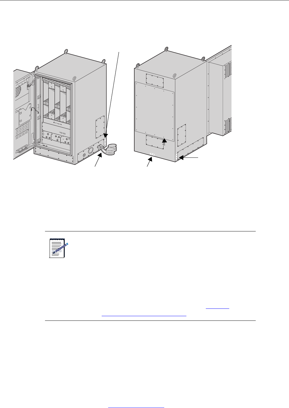
Chapter 4 ● Installing the cabinet, power, and ground
68 Release 2.0, 910056 Rev01d
Procedure
1. Locate the two ground wires protruding from the lower right hand side of the cabinet.
2. Connect both ground wires to the site ground rod.
The method of connecting the grounding wires to the site grounding system varies. The particular
method you use depends on many factors. The rods can be connected to separate grounding rods or
external grounding plates. The connection can be welded, terminal lugs can be used, or a different type
of connection can be used. Follow local codes and practise as appropriate for local conditions.
3. Optionally (and in addition to main ground connection), connect the site ground system to the optional
three pairs of grounding contacts (see A, B, and C in the above figure).
• Two ground points are on the bottom rear of the IP-RN 8000 enclosure
• Two ground points are located next to the access panels on the right rear of the IP-RN 8000.
• Two ground points are located next to the access panels on both the left rear of the IP-RN 8000.
These optional ground points are threaded double hole lugs. The thread is 1/14-20.
This procedure is complete. Go to Testing primary power on page 69.
NOTE
• The grounding coils can be trimmed to an appropriate
length. Do not cut them too short as they are difficult
to replace.
• If you will need to remove the right side access panel
after the grounding coils have been connected to the
site grounding infrastructure, consider running the
ground coil wires straight out from the cabinet for
one foot. This enables backing the access panel away
from the cabinet without disconnecting and
straightening out the grounding coils. See Planning
conduit and grounding installation on page 53.
Required main ground wires
Optional side ground points (A)
Optional rear ground points (B)
Optional Side ground points (C)
IP-RN 8000 front/right view IP-RN 8000 rear/left view
Testing primary power
IP-RN 8000 Installation & Commissioning Guide 69
Testing primary power
This procedure explains how to test whether power is applied to the IP-RN 8000, whether the voltage is at
the correct nominal level at the cabinet’s power terminals, and whether power is distributed internally.
Be sure you have read and understood Understanding the cabinet installation process on page 50 before
continuing.
Requirements
No tools are required.
Procedure
1. Open the front door and visually examine the compartment for loose wires or components.
2. Pull the backhaul cable(s) ends forward and through the power terminal access panel.
CAUTION
Take all appropriate safety precautions before closing the main
circuit breaker and turning on power. Failure to do so can result in
personal injury and equipment damage.
CAUTION
Do not perform this procedure in the raid or injury or death may
occur.
CAUTION
All connections must be tight and all components secured before
continuing. Loose connections or components can cause short
circuits and injure or kill nearby persons and damage equipment.
WARNING
Pulling the backhaul cable ends out of the cabinet through the
power terminal access panel is necessary to prevent short circuits,
to prevent danger, and protect equipment.
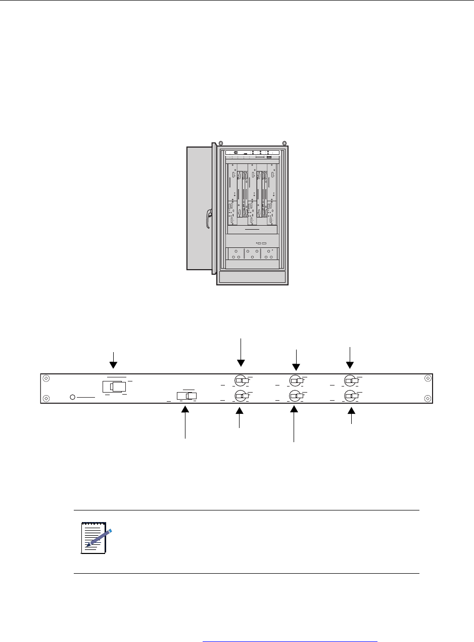
Chapter 4 ● Installing the cabinet, power, and ground
70 Release 2.0, 910056 Rev01d
3. Ensure the power supply at the power terminal is as the correct voltage level.
a. Connect a volt meter to the power terminal by connecting the positive volt meter lead to the
positive cabinet power terminal and the negative lead to the negative terminal.
b. The volt meter should show voltage at 27 V DC nominal.
c. Disconnect the volt meter.
4. Locate the Power Distribution Unit (PDU).
5. Ensure all power switches on the PDU panel are set to OFF (flipped to the right).
6. Close the external circuit breaker to apply power to the IP-RN 8000.
7. Flip the Main Power switch on the PDU to the left to enable main power.
The PDU’s Main Power Status LED lights green indicating power flow. If the LED does not light green,
open the external circuit breaker to disable power application to the cabinet and contact Airvana.
For information about the PDU, see Understanding the Power Distribution Unit on page 27.
NOTE
This circuit breaker is external equipment that is not provided by
Airvana.
Main Power
Chassis power (CHAS)
Heat exchanger (HXCH)
Alarms (ALRM) USR1
Heater (HEAT)
Fans (FANS)
USR2
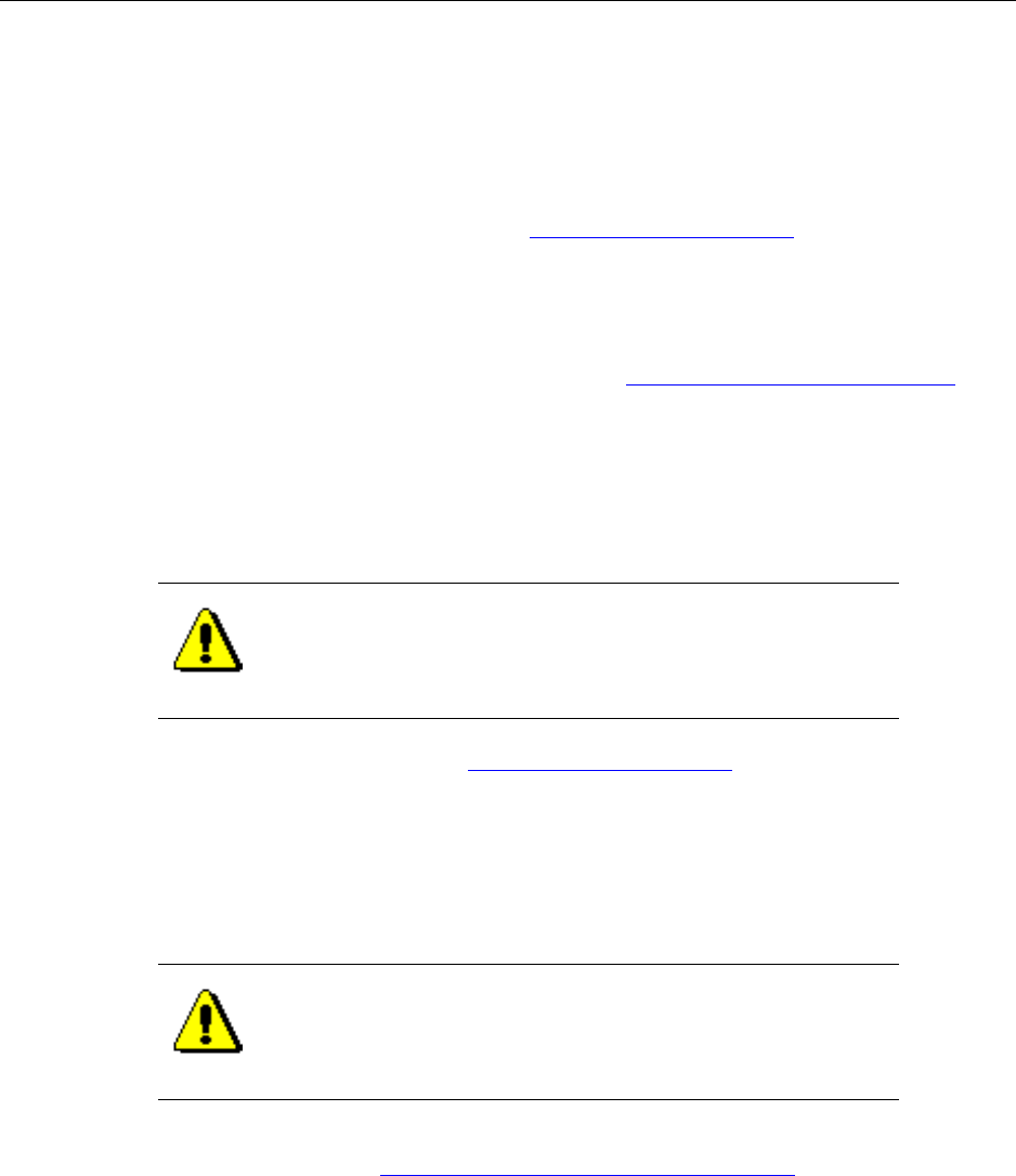
Testing primary power
IP-RN 8000 Installation & Commissioning Guide 71
8. Flip the ALRM power switch on the PDU to the left to enable power application to the Alarm Unit and
to the Heat Exchanger controller.
a. To test whether power is applied to the Alarm Unit, press in the Alarm Test button at the lower left
corner of the Alarm Unit.
All 20 alarm LEDs light red indicating power application. If the LEDs do not light red, contact
Airvana.
For information about the Alarm Unit, see Understanding the Alarm Unit on page 29.
b. To test whether power is applied to the Heat Exchanger controller, watch the Heat Exchanger
LEDS.
During a period of initialization that may last several minutes, the LEDs blink. Then the top two
LEDs light green and the bottom two light RED. Contact Airvana if the LEDs do not light.
For information about the Heat Exchanger LEDs, see Understanding cabinet right side view on
page 5.
9. Flip the FANS switch to the left on the Power Distribution Unit.
To test whether power is applied to the Fan Unit, listen for the sound of the fan and/or carefully insert
your hand into a module slot and feel a breeze moving upwards. If the Fan Unit is not operative, contact
Airvana.
For information about the Fan Unit, see Understanding the Alarm Unit on page 29.
10. Flip the HXCH switch to the left to apply power to the heat exchanger.
All four Heat Exchanger LEDs light green.
11. Flip the Main Power switch to the right to turn off power application to the IP-RN 8000.
12. Open the main circuit breaker to disconnect the IP-RN 8000 from its power source.
This procedure is complete. Go to Understanding the backhaul installation process on page 74.
CAUTION
If you place your hand in an empty module slot to try to feel a
breeze to verify that the fan is operating, do not allow your fingers
or hand to move below the module slots or you may touch
moving fan blades and injury can occur.
CAUTION
Ensure you disconnect the IP-RN 8000 from its power source by
opening its external main circuit breaker before doing anything
else. Failure to do so could result in personal injury or equipment
damage.

Chapter 4 ● Installing the cabinet, power, and ground
72 Release 2.0, 910056 Rev01d

IP-RN 8000 Installation & Commissioning Guide 73
Chapter 5
Connecting the backhaul
About this chapter
This chapter explains how to thread the backhaul link(s) through the cabinet and wire the
backhaul(s) into the backhaul punch block. This chapter has the following sections:
•Understanding the backhaul installation process on page 74
•Understanding backhaul links on page 75
•Removing the punch block access panel on page 76
•Routing backhaul to the backhaul punch block on page 77
•Wiring backhaul to the backhaul punch block on page 79
•Re-installing the access panels on page 83

Chapter 5 ● Connecting the backhaul
74 Release 2.0, 910056 Rev01d
Understanding the backhaul installation process
This process explains all steps and procedures to follow when installing the backhaul.
1. Ensuring all grounding and surge protection equipment is in place
Do not perform any work on the IP-RN 8000 until you have installed grounding and external surge
protection equipment.
See Understanding surge protection and grounding on page 33.
2. Ensuring the backhaul cable is already installed into the cabinet base
See Routing power and backhaul cables into cabinet and closing right side access panel on page 64.
3. Removing the punch block access panel
The punch block access panel and the power terminal access panel must be removed to gain access to
the punch block.
See Removing the punch block access panel on page 76.
4. Routing backhaul to the backhaul punch block
The backhaul is threaded from the bottom of the cabinet in the power terminal access panel area,
through cinch blocks, and up the inside of the left side of the cabinet to the backhaul punch block.
See Routing backhaul to the backhaul punch block on page 77.
5. Connecting backhaul to backhaul punch block
The backhaul is wired into the backhaul punch block.
See Wiring backhaul to the backhaul punch block on page 79.
6. Re-installing access panels
The backhaul punch block access panel and the power terminal access panel are re-installed.
See Re-installing the access panels on page 83.
This procedure is complete. This process is complete. You must connect the antennas. Go to Understanding
the antenna installation process on page 86.
TIP
During the commissioning phase, backhaul links are tested with
loopback tests. These tests require installing an external loopback
on each link. If you plan to install the loopback into the punch
block itself, the backhaul will have to be un-installed, then
re-installed after the loopback test. In this case, it may make sense
to postpone backhaul installation until after the loopback tests are
performed. For more information, see Chapter 13, Loopback
testing backhaul links.

Understanding backhaul links
IP-RN 8000 Installation & Commissioning Guide 75
Understanding backhaul links
The backhaul connects the IP-RN 8000 to the IP-RNC 8500 and carries user traffic (access terminal to
Internet) and management traffic (AirVista to IP-RN 8000). See Understanding the backhaul punch block
and switch on page 32.
Backhaul deployment/installation options are as follows:
• One to four T1/E1 leased lines
The combined total bandwidth of the T1/E1 leased lines is available for backhaul traffic.
The backhaul switch makes the total T1/E1 backhaul bandwidth available to whichever BIO/SC is
currently active. (In non-redundant systems, there is only one BIO/SC, typically in slot 3).
• Or, one or two 10/100 Mbit/sec Ethernet links
The bandwidth of a single Ethernet is available at a time for backhaul traffic because the Ethernets are
not switched between the BIO/SCs like T1/E1s Instead the Ethernet link(s) pass directly through the
backhaul switch and are directly connected to each BIO/SC module(s).
If you are using Ethernet backhauls on a redundant system with two Digital Module Kits, you must
install two Ethernet backhauls.
Non-redundant digital module kits require only a single Ethernet backhaul.
Backhaul cable specifications are as follows:
• T1 — 100 ohm twisted pair cable complying with ANSI/EIA/TIA 568
• E1 — 120 ohm twisted pair cable
• Ethernet— Cat5 cable or better. Ensure the cable can withstand the temperature range inside the
cabinet.
NOTE
The backhaul cable(s) installed should have connectors on the far
end that are appropriate for the application. For example, if
Ethernet backhauls are used, the far end of the cables should have
Ethernet connectors that are appropriate for the Ethernet switch,
patch panel, router, or other device that the cables will connect to
(typically RJ-45 modular jacks).
CAUTION
Make sure that temperature specification of the Ethernet cable
you provide is within the expected operational temperature limits
of the inside of the cabinet. See Table 27 on page 192.

Chapter 5 ● Connecting the backhaul
76 Release 2.0, 910056 Rev01d
Removing the punch block access panel
This procedure explains how to remove the punch block access panel.
Be sure you have read and understood Understanding the backhaul installation process on page 74 before
continuing.
Requirements
• Number 2 Phillips head screwdriver
Procedure
1. Ensure that power is not being delivered to the IP-RN 8000.
a. Ensure the Main Power switch on the Power Distribution Unit is flipped to the right.
See Understanding the Power Distribution Unit on page 27.
b. Ensure the external circuit breaker that controls power flow to the IP-RN 8000 is opened,
eliminating power on the IP-RN 8000 circuit.
2. Locate the punch block access panel.
See Understanding access panels on page 9.
3. Using a number 2 Phillips head screw driver, remove the three screws that hold the access panel in
place.
4. Set the access panel and the three screws aside for later re-installation
5. Ensure the power terminal access panel has been removed.
If the power terminal access panel is not currently removed, follow the procedure explained in
Removing the power terminal access panel on page 204.
This procedure is complete. Go to Routing backhaul to the backhaul punch block on page 77.
WRIST
STRAP
Wear an ESD strap and connect the strap to the ESD jack in the
Antenna Interface Unit when performing any installation
procedure. See Understanding the Antenna Interface Unit module
on page 17.
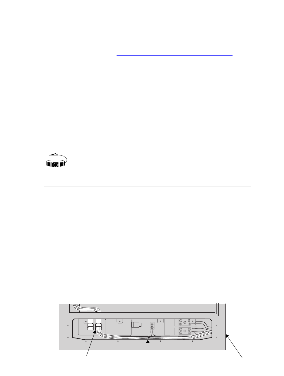
Routing backhaul to the backhaul punch block
IP-RN 8000 Installation & Commissioning Guide 77
Routing backhaul to the backhaul punch block
This procedure explains how to thread the backhaul cable(s) from the base of the cabinet up to the backhaul
punch block in preparation for wiring the cables to the punch block. This procedure assumes that power is
not being delivered to the cabinet.
Be sure you have read and understood Understanding the backhaul installation process on page 74 before
continuing.
Requirements
• Small slotted screw driver
• Cable ties to wrap cables into a single bunch. (Ties are unnecessary if there is only a single cable.)
Procedure
1. Ensure there is five feet of backhaul cable inside the cabinet for each backhaul link.
If there is not five feet of cable inside the cabinet, reach into the cabinet base through the power terminal
access area and pull five feet of backhaul cable into the cabinet.
2. Thread the backhaul cable(s) through one of the cinch blocks in the left of the power terminal access
area.
Use the small slotted screwdriver to loosen the two screws in the cinch block as needed to make room
for the cable.
If the cable bunch does not fit through one of the cinch blocks, split it into two groups and thread the
cables through both cinch blocks, then re-tie the cables into a single bunch using cable ties.
WRIST
STRAP
Wear an ESD strap and connect the strap to the ESD jack in he
Antenna Interface Unit when performing any installation
procedure. See Understanding the Antenna Interface Unit module
on page 17.
Feed backhaul through power
Lowest part of cabinet front with
Backhaul enters
on right side of cabinet
terminal access area
Thread backhaul through
cinch block and tighten screws
power terminal access panel removed
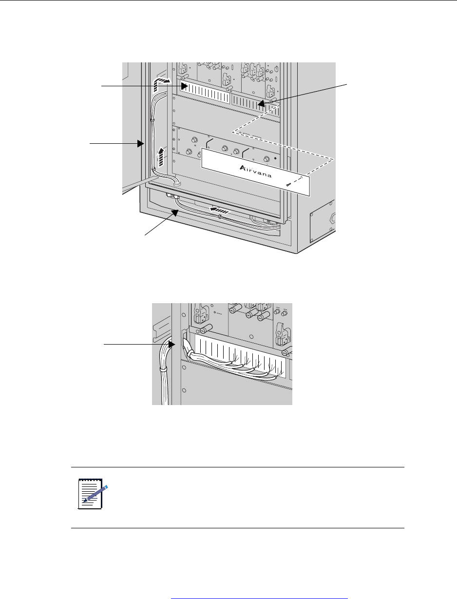
Chapter 5 ● Connecting the backhaul
78 Release 2.0, 910056 Rev01d
3. Thread the backhaul from the cinch block up the left side of the cabinet between the cabinet and the
chassis frame.
4. Pull the end of the backhaul through the opening at the left side of the backhaul punch block
.
5. Tie and dress the backhaul to secure it along its length inside the cabinet and adjust the position of the
cable with regard to the cinch blocks.
6. When the cable is in its final position, tighten the two screws on the cinch block to hold it securely in
place.
This procedure is complete. Go to Wiring backhaul to the backhaul punch block on page 79.
NOTE
Be sure to tie the backhaul cables securely to the frame to the left
of the punch block to provide stain relief for the wiring into the
punch block.
Backhaul
punch block
Backhaul cable
Punch block
access panel
Tie and dress
backhaul and thread
through cabinet side
Alarm punch block
(right half)
Pull cable end
through opening
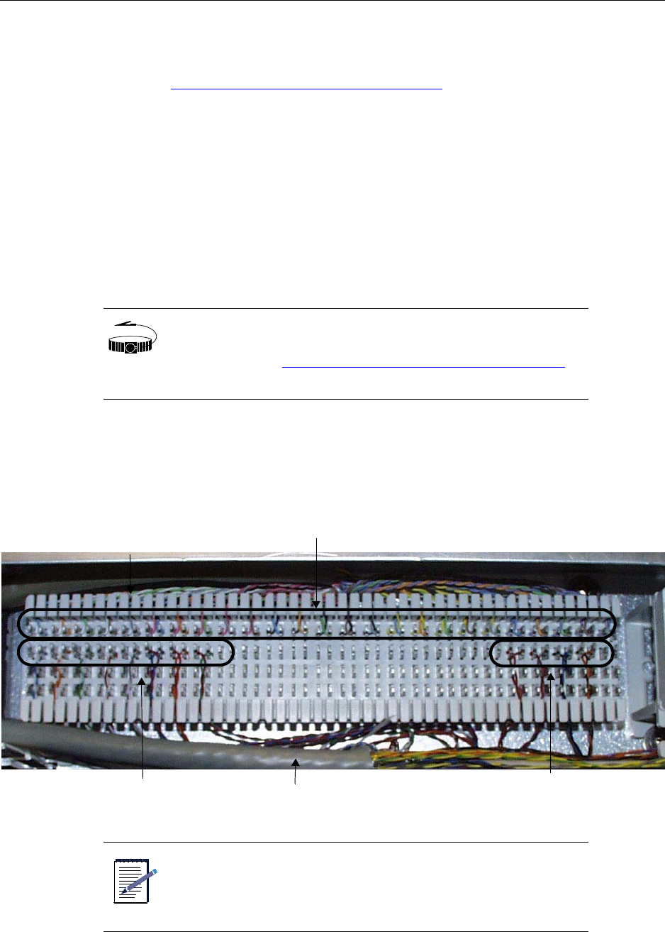
Wiring backhaul to the backhaul punch block
IP-RN 8000 Installation & Commissioning Guide 79
Wiring backhaul to the backhaul punch block
This procedure explains how to connect the backhaul wires to the backhaul punch block. Be sure you have
read and understood Understanding the backhaul installation process on page 74 before continuing.
Requirements
• Wire cutters
• Electrician’s tool or knife to peel back wire coatings
• Standard punch down tool for type 66-Block punch block.
Procedure
1. Familiarize yourself with the backhaul punch block.
The punch block is of type 66-Block. The punch block terminal positions onto which you punch down
wires are numbered from left to right, from 1 to 50. V-shaped notches in the plastic below and above the
punch block terminals separate the terminal positions into groups of 10 to make it easier to find the
correct terminal to punch into.
WRIST
STRAP
Wear an ESD strap and connect the strap to the ESD jack in he
Antenna Interface Unit when performing any installation
procedure. See Understanding the Antenna Interface Unit module
on page 17.
NOTE
Simultaneous use of Ethernet and T1/E1 backhauls as shown in is
not supported in software. You can only enable use one type or
the other type at any one time.
Four T1s/E1s punched into
positions 1 through 16
Airvana pre-installed internal wiring with AT&T color codes
Two Ethernets punched into
positions 41 through 48
Backhaul cable(s)
V-shaped notches separate
groups of 10 terminals

Chapter 5 ● Connecting the backhaul
80 Release 2.0, 910056 Rev01d
2. Use Table 19to determine the backhaul cable wires to punch into the terminal positions.
Table 19 Backhaul punch block pin-out
Airvana wire color
code (pre-wired into
the punch block)
Backhaul wire signal description
Punch
down
position
white wire/blue stripe T1/E1 backhaul number 1. Transmit. Positive (tip) 1
blue wire/white stripe T1/E1 backhaul number 1. Transmit. Negative (ring) 2
white wire/orange stripe T1/E1 backhaul number 1. Receive. Positive (tip) 3
orange wire/white stripe T1/E1 backhaul number 1. Receive. Negative (ring) 4
white wire/green stripe T1/E1 backhaul number 2. Transmit. Positive (tip) 5
green wire/white stripe T1/E1 backhaul number 2. Transmit. Negative (ring) 6
white wire/brown stripe T1/E1 backhaul number 2. Receive. Positive (tip) 7
brown wire/white stripe T1/E1 backhaul number 2. Receive. Negative (ring) 8
white wire/slate stripe T1/E1 backhaul number 3. Transmit. Positive (tip) 9
slate wire/white stripe T1/E1 backhaul number 3. Transmit. Negative (ring) 10
red wire/blue stripe T1/E1 backhaul number 3. Receive. Positive (tip) 11
blue wire/red stripe T1/E1 backhaul number 3. Receive. Negative (ring) 12
red wire/orange stripe T1/E1 backhaul number 4. Transmit. Positive (tip) 13
orange wire/red stripe T1/E1 backhaul number 4. Transmit. Negative (ring) 14
red wire/green stripe T1/E1 backhaul number 4. Receive. Positive (tip) 15
green wire/red stripe T1/E1 backhaul number 4. Receive. Negative (ring) 16
red wire/slate stripe Not used 17
slate wire/red stripe 18
red wire/brown stripe Not used 19
brown wire/red stripe 20
black wire/blue stripe Not used 21
blue wire/black stripe 22
black wire/orange stripe Not used 23
orange wire/black stripe 24
black wire/green stripe Not used 25
green wire/black stripe 26
black wire/brown stripe Not used 27
brown wire/black stripe 28

Wiring backhaul to the backhaul punch block
IP-RN 8000 Installation & Commissioning Guide 81
3. Find the correct punch down terminal positions on the punch block by counting from the left or by using
the color of the Airvana pre-installed wire.
Airvana uses AT&T punch block wire color coding.
black wire/slate stripe Not used 29
slate wire/black stripe 30
yellow wire/blue stripe Not used 31
blue wire/yellow stripe 32
yellow wire/orange stripe Not used 33
orange wire/yellow stripe 34
yellow wire/green stripe Not used 35
green wire/yellow stripe 36
yellow wire/brown stripe Not used 37
brown wire/yellow stripe 38
yellow wire/slate stripe Not used 39
slate wire/yellow stripe 40
violet wire/blue stripe Primary Ethernet backhaul. Transmit. Positive (tip) 41
blue wire/violet stripe Primary Ethernet backhaul. Transmit. Negative (ring) 42
violet wire/orange stripe Primary Ethernet backhaul. Receive. Positive (tip) 43
orange wire/violet stripe Primary Ethernet backhaul. Receive. Negative (ring) 44
violet wire/green stripe Redundant Ethernet backhaul. Transmit. Positive (tip) 45
green wire/violet stripe Redundant Ethernet backhaul. Transmit. Negative (ring) 46
violet wire/brown stripe Redundant Ethernet backhaul. Receive. Positive (tip) 47
brown wire/violet stripe Redundant Ethernet backhaul. Receive. Negative (ring) 48
violet wire/slate stripe Not used 49
slate wire/violet stripe 50
Table 19 Backhaul punch block pin-out (continued)
Airvana wire color
code (pre-wired into
the punch block)
Backhaul wire signal description
Punch
down
position
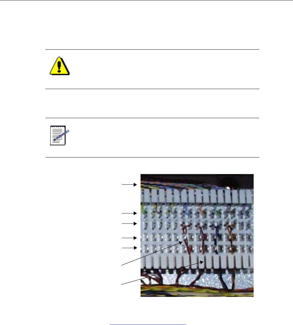
Chapter 5 ● Connecting the backhaul
82 Release 2.0, 910056 Rev01d
4. Using standard punch block wiring techniques, punch the backhaul wires into the backhaul punch
block.
Ensure each wire pair is twisted evenly to within 1/2 inch of the terminal.
Ensure the wire pair is threaded through the slot beneath the terminal.
This procedure is complete. Go to Re-installing the access panels on page 83.
CAUTION
If the untwisting of the wire pairs occurs more than 1/2 inch from
the terminal the backhaul may not operate correctly.
NOTE
You cannot use the punch block’s bottom two rows (labeled
“Unused” in the figure below). These rows are not connected
internally.
Airvana internal color coded wiring
Pre-installed color coded wires
You punch down into this row
Unused
Twist wire pairs evenly to
Unused
within 1/2 inch of the terminal
Thread wire pairs through
slot below terminal

Re-installing the access panels
IP-RN 8000 Installation & Commissioning Guide 83
Re-installing the access panels
This procedure explains how to re-install the backhaul access panel and the power terminal access panel.
Be sure you have read and understood Understanding the backhaul installation process on page 74 before
continuing.
Requirements
• Number 2 Phillips head screwdriver
Procedure
1. Retrieve the three Phillips head screws and the punch block access panel previously set aside.
2. Hold the panel in place over the back haul punch block and start the three screws by hand.
3. Tighten the three screws snugly. Do not over tighten or you might strip the screw threads.
4. Re-install the power cable access panel.
Go to Re-installing the power terminal access panel on page 205.
This procedure is complete. Go to Understanding the antenna installation process on page 86.
WRIST
STRAP
Wear an ESD strap and connect the strap to the ESD jack in he
Antenna Interface Unit when performing any installation
procedure. See Understanding the Antenna Interface Unit module
on page 17.

Chapter 5 ● Connecting the backhaul
84 Release 2.0, 910056 Rev01d

IP-RN 8000 Installation & Commissioning Guide 85
Chapter 6
Connecting antennas
About this chapter
This chapter explains how to install the Rox System cabinet seal and how to connect RF and GPS
antennas internally and externally. This chapter has the following sections:
•Understanding the antenna installation process on page 86
•Understanding the antenna installation process on page 86
•Removing access panels on page 91
•Installing the Rox System cabinet seal on page 94
•Connecting GPS and RF antennas on page 96

Chapter 6 ● Connecting antennas
86 Release 2.0, 910056 Rev01d
Understanding the antenna installation process
This process explains all steps and procedures to follow when connecting RF and GPS antenna cables.
1. Understanding cautions and warnings
Understand and follow all warnings and cautions or injury, death, or damage to equipment can occur.
See Understanding warnings and cautions on page 87.
2. Understanding the Rox System
This section explains the pre-assembled configuration in which the Rox System ships.
See Understanding the pre-assembled Rox System on page 87.
You can optionally assemble your own Rox System.
See Optionally assembling your own Rox on page 89.
3. Removing access panels
Remove the antenna access panel in order to install the Rox System cabinet seal. You must also remove
the surge protection access panel in order to connect Rox System antenna cables internally to the surge
protection bar.
See Removing access panels on page 91
4. Installing the Rox System cabinet seal
The Rox System cabinet seal must be installed into the cabinet opening created when you remove the
antenna access panel on the top back of the cabinet. Installation involves routing the cables into the
cabinet and screwing the Rox System cabinet seal into place.
See Installing the Rox System cabinet seal on page 94.
5. Connecting GPS and RF antennas
All antenna cables routed through the Rox System cabinet seal must be connected to the surge
protection bar on the inside of the cabinet and to external antenna cables/surge protection equipment on
the outside of the cabinet. The surge protection access panel must be re-installed.
See Connecting GPS and RF antennas on page 96.
This procedure is complete. This process is complete. You must install modules. Go to Understanding the
module installation process on page 104.
Understanding warnings and cautions
IP-RN 8000 Installation & Commissioning Guide 87
Understanding warnings and cautions
This section contains warnings and cautions that apply to all procedures in this chapter.
Be sure you have read and understood Understanding the antenna installation process on page 86 before
continuing.
Understanding the pre-assembled Rox System
The Rox System cabinet seal typically ships pre-assembled and is ready to install. The pre-assembled Rox
System cabinet seal supports:
• Three radio sectors
• Each radio sector has two RF antenna cables. One cable carries two signals, a transmit signal and a
receive signal. The second contains a single receive antenna cable.
• Two GPS antenna cables — one primary GPS antenna and one redundant GPS antenna
WARNING
Do not perform any of these procedures when there is a
possibility of lightning strikes. Death or injury could occur if
lightning strikes during installation.
WARNING
Upon installation, this product is required to comply with the
requirements of Federal Communications Commission 47CFR
1.1310, Radiofrequency radiation exposure limits. Care must be
taken by the installer to insure that the antenna chosen along with
its installation position and orientation does not violate these
limits.
WARNING
Do not perform any of these procedures if the IP-RN 8000 has not
been properly grounded.
WRIST
STRAP
Wear an ESD strap and connect the strap to the ESD jack in the
Antenna Interface Unit when performing any installation
procedure. See Understanding the Antenna Interface Unit module
on page 17.
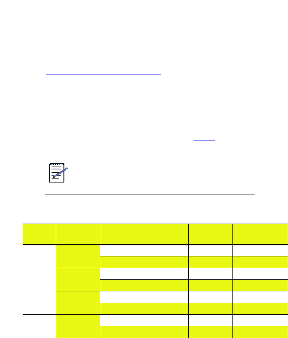
Chapter 6 ● Connecting antennas
88 Release 2.0, 910056 Rev01d
The pre-assembled Rox System can be used on installations with:
• One, two, or three radio sectors. See Understanding radio sectors on page 13.
If fewer than three radio sectors are used at a particular installation, the unused RF antenna cables
exiting through the Rox System cabinet seal must be connected to external surge suppression equipment
to prevent equipment damage from lightning strikes.
• Redundant and non-redundant Digital Module Kits.
Redundant installations use two GPS antennas; non-redundant installations use a single GPS antenna.
(See Understanding Digital Module Kit redundancy on page 20.) In non-redundant installations, the
secondary GPS antenna cable must be connected to external surge suppression equipment to prevent
damage from lightning strikes.
The pre-assembled Rox System cannot be used for installations that have three separate RF antenna cables
for each radio sector. In this case, you must use a specially-ordered Rox System cabinet seal with nine RF
cables.
The pre-assembled Rox System is shipped fully assembled with cables that are 8 feet long, 3/8 inch or 1/2
inch in diameter, and have male N-Type connectors at both ends. See Table 20.
NOTE
If you special ordered a Rox System cabinet seal, or assembled it
yourself, you might have a different number of cables and
different connector types.
Table 20 The standard Rox System cabinet seal assembly
Type Sector Use label Connector
(both ends)
RF alpha Receive antenna cable α RX1 male N-type
Transmit and receive antenna cable α TX/RX0 male N-type
beta Receive antenna cable β RX1 male N-type
Transmit and receive antenna cable β TX/RX0 male N-type
gamma Receive antenna cable χ RX1 male N-type
Transmit and receive antenna cable χ TX/RX0 male N-type
GPS not applicable primary GPS antenna cable GPS_P male N-type
secondary GPS antenna cable GPS_R male N-type

Optionally assembling your own Rox
IP-RN 8000 Installation & Commissioning Guide 89
Optionally assembling your own Rox
You can optionally assemble your own Rox System cabinet seal. If you are not assembling your Rox System
cabinet seal, you can skip this section.
With this option, Airvana provides the Rox System cabinet seal and related components, but you must
provide the antenna cables and cable connectors.
Airvana Rox kits
This Airvana Rox Kit consists of the following:
• RoxTec Frame Kit, ES-CF-16, quantity: 1
• RoxTec Module Kit, ES-CM-20 w40, quantity: 8
• Mounting Plate with gaskets, quantity: 1
For more additional information about the Rox Kit, you can contact RoxTec. The Rox Kit is identified by
part number 6000-004652-100
Assembly requirements
When assembling Rox System cabinet seals, you must adhere to the following requirements. These
requirements are for installation in the top rear antenna access panel opening.
Requirements:
• Internal connectors: N-type, male, straight, hex
• External connectors: site specific, defined by customer
• Length of internal cables: 21 inches, measured from inside edge of Rox System to the end of connector
• Overall cable length: site specific, defined by customer (21 inches internal length + 1.5 inches Rox
thickness + user defined external length)
• Cable size: maximum overall diameter (OD) of 14.5mm (0.571 inches) including sheath; minimum OD
of 4 mm (0.157 inches) of cable screen
• Cable type: defined by customer (suggested type: Andrew Corporation Part #FSJ4-50B, 1/2 inch 50
ohm Superflex or Times Microwave LMR400DB with EZ connectors)
CAUTION
If you assemble the Rox System cabinet seals, you are responsible
for any damage resulting from improper assembly. Ensure that
only qualified personnel perform the assembly.
Chapter 6 ● Connecting antennas
90 Release 2.0, 910056 Rev01d
RF and GPS cable locations
Airvana recommends installing the RF and GPS cables into the positions in the Rox System cabinet seal that
are shown in Figure 20. This enables determination of which cable serves which function after the Rox
System cabinet seal has been installed even if cable labels are missing. This recommendation is for a three
sector node, with two RF antennas per sector, and in a redundant configuration requiring two GPS cables.
Figure 20 Recommended cable positions in Rox System viewed from the external side of the Rox
TIP Cables should be labeled as to their function on both the internal
side and the external side of the Rox System cabinet seal.
Table 21 Recommended cable positions in Rox System cabinet seal
Position Cable description
1 Redundant GPS cable
3 TX/RX0 cable for gamma sector
5 TX/RX0 cable for beta sector
7 TX/RX0 cable for alpha sector
10 RX1 cable for gamma sector
12 RX1 cable for beta sector
14 RX1 cable for alpha sector
16 Primary GPS cable
View from the outside of the cabinet
13 57
10 12 14 16
Key:
Position numbers refer to table below
Gray circles show unused cable positions

Removing access panels
IP-RN 8000 Installation & Commissioning Guide 91
Removing access panels
This procedure explains how to remove the two required access panels in order to install the Rox System
Cabinet seal and connect all antennas.
Be sure you have read and understood Understanding the antenna installation process on page 86 before
continuing.
Requirements
• 5/32 tamper-resistant screw driver
• Thread tapping kit with 1/4-20 thread bit at 3/4 inch depth
Procedure
1. Ensure that power is not being delivered to the IP-RN 8000.
a. Ensure the Main Power switch on the Power Distribution Unit is flipped to the right.
See Understanding the Power Distribution Unit on page 27.
b. Ensure the external circuit breaker that controls power flow to the IP-RN 8000 is opened,
eliminating power on the IP-RN 8000 circuit.
2. Locate the antenna access panel on the cabinet where you will install the Rox System.
There are four antenna access panels. The Rox System can be installed into any one of the cabinet
openings created when the access panels are removed.
The standard configuration requires installing the Rox System into the access panel on the top of the
back of the cabinet.
NOTE
Installing the Rox System cabinet seal into any of the three
non-standard access panels requires a different internal
configuration of the cabinet, and it must have been specially
ordered.
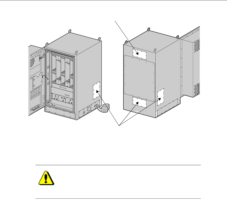
Chapter 6 ● Connecting antennas
92 Release 2.0, 910056 Rev01d
3. Remove the 10 screws from the antenna access panel with the tamper-proof screwdriver, being careful
not to let the access panel fall when the final screw is removed.
4. Set aside the 10 antenna access panel screws and washers.
The screws and washers will be required for installing the Rox System cabinet seal.
The antenna access panel cover that you just removed will not be required for this installation. Save it
for later use as appropriate.
5. Locate the surge protection access panel.
CAUTION
Access panels must be handled carefully. If they are bent they
may not form a proper seal with the cabinet when they are
re-installed. An intact seal on the inside edge of the access panel
is required to ensure external environmental conditions are sealed
out.
Non-standard Rox System installation panels
Standard Rox System cabinet seal installation panel
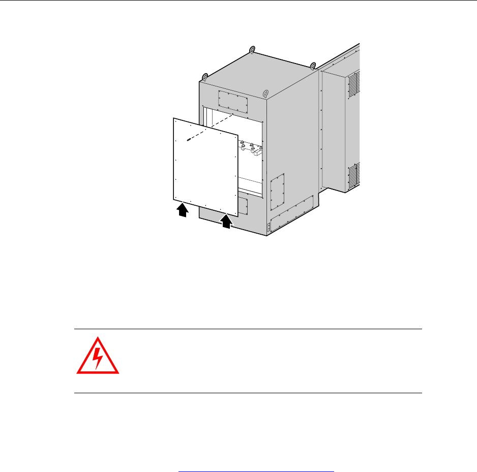
Removing access panels
IP-RN 8000 Installation & Commissioning Guide 93
6. Remove 15 of the 16 screws holding the surge protection access panel in place. Leave the top middle
screw in place.
7. Hold the surge protection access panel firmly in place and remove the final screw using the tamper
resistant screw driver.
8. Set aside all 16 screws and washers from the surge protection access panel.
These screws will be used to re-install the access panel after all antennas are connected.
This procedure is complete. Go to Installing the Rox System cabinet seal on page 94.
WARNING
The surge protection access panel is heavy. Take all necessary
precautions to avoid injury and to avoid damaging the access
panel. Do not allow it to be bent. Do not allow the seal around the
inside edge to be damaged.
Surge protection access panel
Cabinet back view
Take care. The access panel is
heavy and requires support

Chapter 6 ● Connecting antennas
94 Release 2.0, 910056 Rev01d
Installing the Rox System cabinet seal
This procedure explains how to install the Rox System cabinet seal. This procedure assumes that the power
supply has been turned off and that power is not flowing to the cabinet.
Be sure you have read and understood Understanding the antenna installation process on page 86 before
continuing.
Requirements
• 5/32 inch tamper-resistant screw driver
• Torque wrench with bit for 5/32 inch tamper-resistant screw driver
• Thread tapping kit with 1/4-20 thread bit at 3/4 inch depth
Procedure
1. Remove the Rox System cabinet seal from its box and remove all packing materials.
2. Retrieve the 10 access panel screws and the corresponding rubber washers that you set aside when you
removed the antenna access panel.
3. Examine the back side of the Rox System cabinet seal.
• The gasket along the edge must be undamaged to ensure a proper seal.
• A spacing washer must be embedded in the gasket for each screw. See Connectors, screws, nuts,
washers on page 194.
4. Examine all cable labels. Each cable should be labeled at both ends.
If any label is not present, trace the cable through the Rox System cabinet seal and attach a label to both
ends of the cable. You must be able to determine which cable on the outside of the Rox System cabinet
seal is associated with which cable on the inside of the Rox System cabinet seal.
5. Hold the Rox System cabinet seal near the open antenna access panel so that its back side faces the
cabinet and thread the 21 inch internal ends of the antenna cables into the top back cabinet hole.
WRIST
STRAP
Wear an ESD strap and connect the strap to the ESD jack in the
Antenna Interface Unit when performing any installation
procedure. See Understanding the Antenna Interface Unit module
on page 17.
NOTE
Be sure not to knock any of the spacer washers off the gasket on
the inside edge of the Rox system cabinet seal. These spacer
washers are required to ensure proper installation and EMI/RF
shielding.
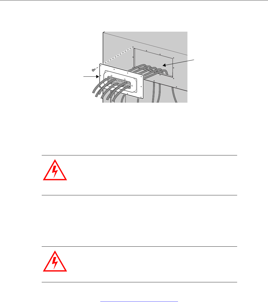
Installing the Rox System cabinet seal
IP-RN 8000 Installation & Commissioning Guide 95
6. Gently push the Rox System cabinet seal against the cabinet and position it for final attachment.
7. Screw in the one of the top middle screws by hand.
Be sure to thread the rubber sealing washer on the screw shank before inserting it in the Rox System
screw hole. Check to ensure each screw shank has a spacing washer as well.
8. Start all screws with rubbers washers in by hand. Install them all loosely before tightening any one of
them.
9. Use a torque wrench with a 5/32 inch tamper-resistant hex drive bit set to 18 inch-pounds to tighten all
screws evenly.
This procedure is complete. Go to Connecting GPS and RF antennas on page 96.
WARNING
Screws should be started by hand. It is possible to damage the
thread in the cabinet if you use a hand tool or a power tool.
Damaged threads must be repaired or the cabinet will be
improperly sealed and the IP-RN 8000 can be damaged. Use a
thread tapping set to fixed damaged threads.
WARNING
If access panels screws are not tightened with the correct torque,
electronic interface may occur causing equipment malfunction.
Rox System cabinet seal
Cabinet back view
positioned for installation
RF and GPS antenna cables
threaded into cabinet
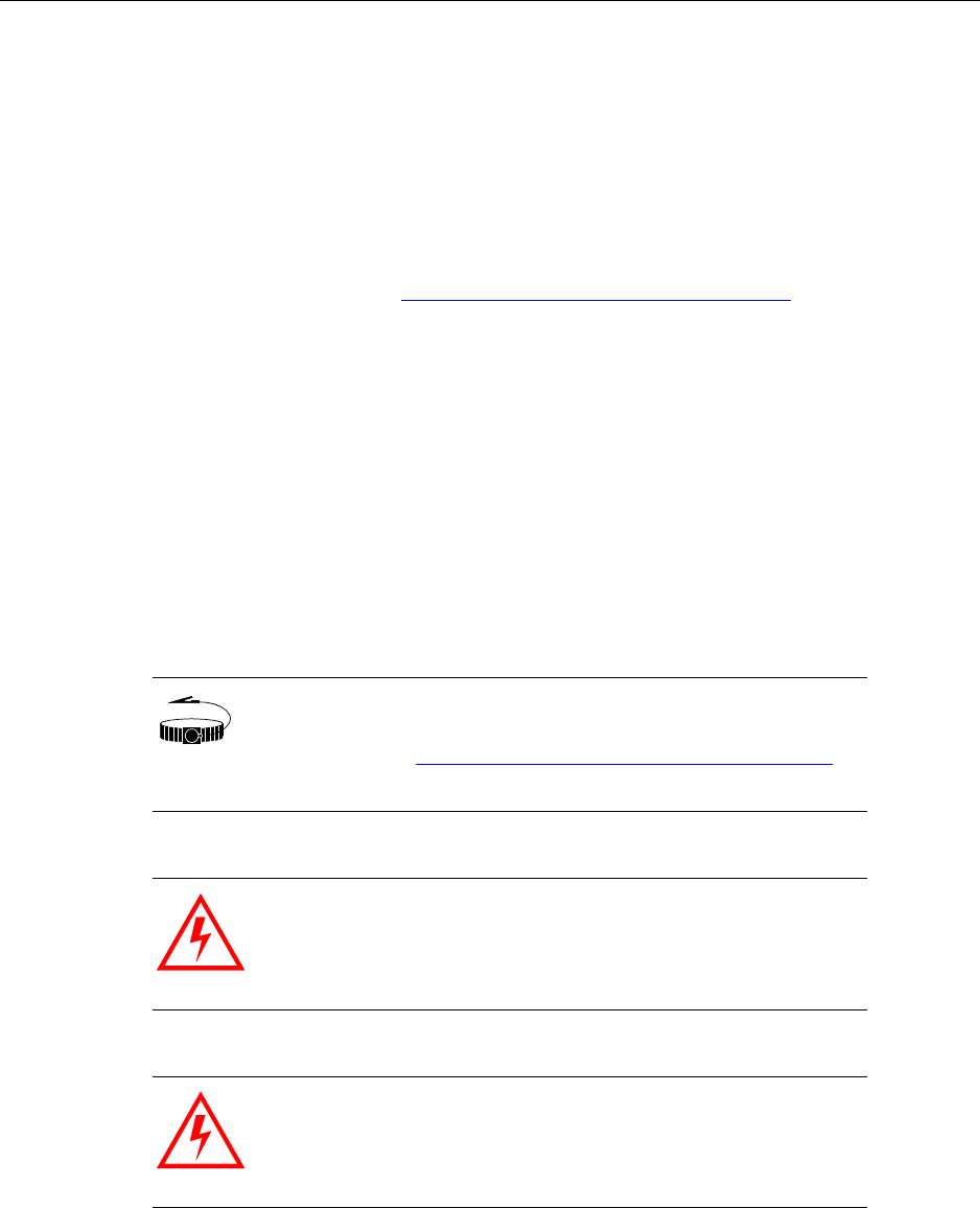
Chapter 6 ● Connecting antennas
96 Release 2.0, 910056 Rev01d
Connecting GPS and RF antennas
This procedure explains how to:
• Connect the GPS and the RF antenna cables to the surge protection bar on the inside of the cabinet and
to a required surge protection system/antenna cables system on the outside of the cabinet
• Re-install the surge protection access panel.
This procedure assumes that the power supply has been turned off and that power is not flowing to the
cabinet.
Be sure you have read and understood Understanding the antenna installation process on page 86 before
continuing.
Requirements
• 13/16 inch open ended wrench
• Torque wrench with 13/16 inch open ended bit
• 5/32 tamper-resistant screw driver
• Thread tapping kit with 1/4-20 thread bit at 3/4 inch depth
Procedure
WRIST
STRAP
Wear an ESD strap and connect the strap to the ESD jack in the
Antenna Interface Unit when performing any installation
procedure. See Understanding the Antenna Interface Unit module
on page 17.
WARNING
Do not touch or connect antennas when there is any chance of a
lightning strike. Injury or death can occur if lightning strikes an
antenna during installation.
WARNING
Antenna cables emit radio frequency energy. Exposure to radio
frequency energy can cause burns or other health problems. Take
all appropriate precautions to avoid risk and danger.
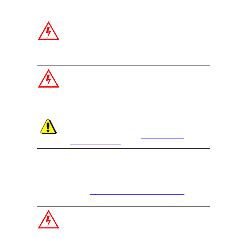
Connecting GPS and RF antennas
IP-RN 8000 Installation & Commissioning Guide 97
1. Look at the surge suppression bar in the cabinet and compare it with that shown in the following figure.
Use the label on each cable to plan which cables dangling from the inside of the Rox System cabinet
seal will connect to which connectors on the surge protection bar.
It is essential that the proper cables are connected to the proper surge suppressors. Each cable on the
Rox System cabinet seal is labeled on both ends, both the end that dangles inside the cabinet and the end
that is outside the cabinet. See Understanding the antenna installation process on page 86.
If your deployment uses two antenna cables per sector, connect the cables to the connectors as follows:
WARNING
Power to the IP-RN 8000 must be turned off.
WARNING
The IP-RN 8000 must be properly grounded before antennas are
installed. Failure to properly ground the IP-RN 8000 can result in
danger to nearby persons and damage to equipment. See
Understanding surge protection and grounding on page 33.
CAUTION
The IP-RN 8000 has a secondary surge suppression system. A
primary external surge suppression system is required to protect
nearby persons from danger should a surge occur and to protect
the IP-RN 8000 from damage. See Understanding surge
protection and grounding on page 33.
WARNING
If you connect cables to the wrong surge suppressors, damage to
equipment may occur and the equipment may not operate
correctly.
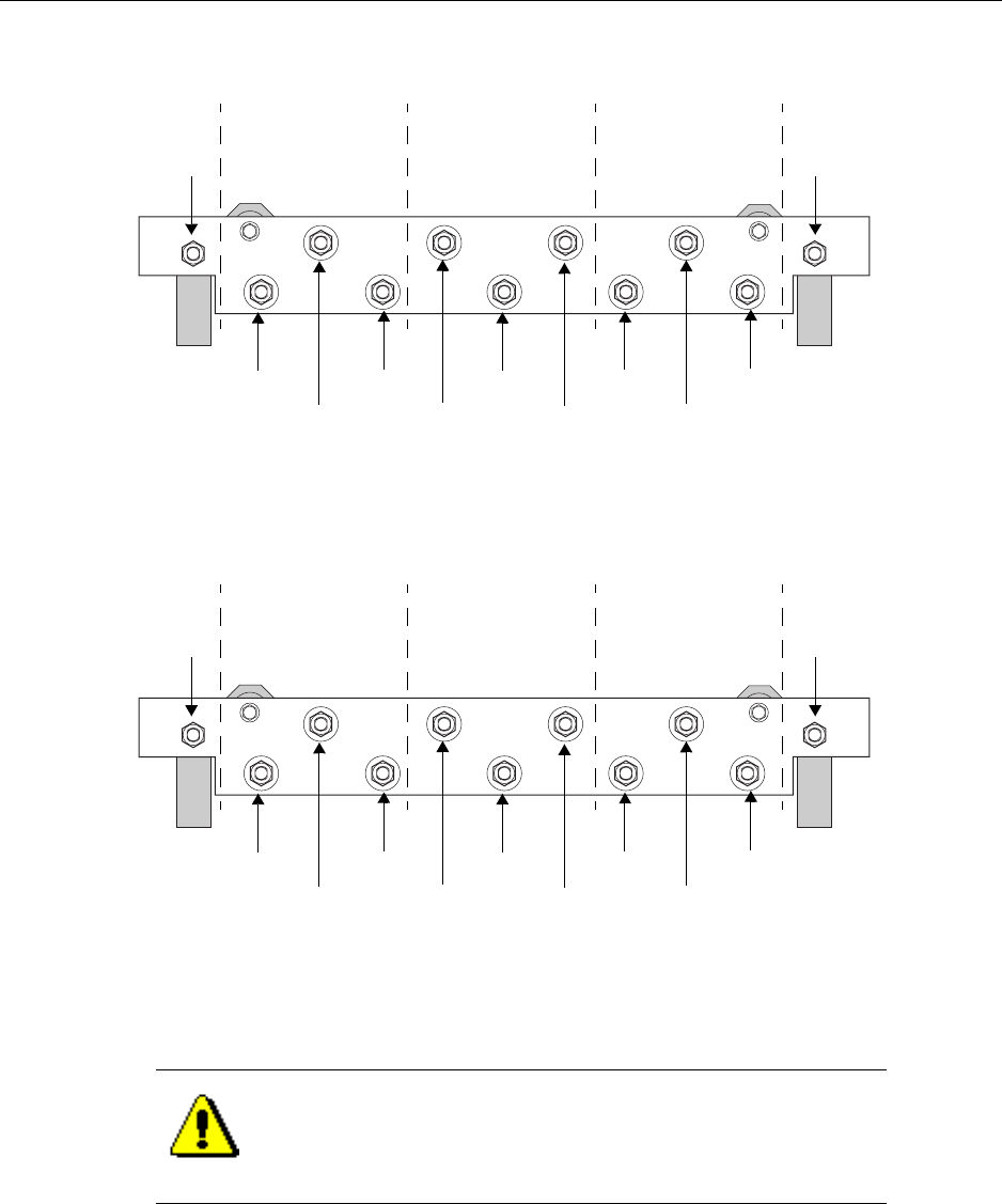
Chapter 6 ● Connecting antennas
98 Release 2.0, 910056 Rev01d
If your deployment uses three antenna cables per sector, connect the cables to the connectors as follows:
2. First finger tighten the RF and GPS antenna cables to the correct surge suppressor connectors on the top
side of the surge protection bar inside the cabinet.
CAUTION
All antenna cables dangling inside the cabinet must be connected
to the surge suppressor connectors, even if they are not connected
to antennas externally. Failure to connect all cables could result in
equipment damage and loss of EMI protection.
Surge suppression bar — top view from the rear
Gamma (χ)
sector
Beta (β)
sector
Alpha (α)
sector
RX1 Unused
TX/RX0 RX1 Unused
TX/RX0 RX1 Unused
TX/RX0
Primary GPSSecondary GPS
Cable connections with two RF cables per sector
Gamma (χ)
sector
Beta (β)
sector
Alpha (α)
sector
RX1 RX0
TX RX1 RX0
TX RX1 RX0
TX
Primary GPSSecondary GPS
Surge suppression bar — top view from the rear
Cable connections with three RF cables per sector
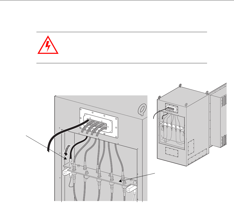
Connecting GPS and RF antennas
IP-RN 8000 Installation & Commissioning Guide 99
3. Use the torque wrench set to 10 inch pounds with the 13/16 inch open ended wrench bit to tighten every
antenna cable connection on the surge suppression bar.
4. After all internal antenna cables are connected to the correct surge suppressors, the cabinet appears as
shown in the following figure.
WARNING
Tightening the connectors to more than 15 inch pounds can
damage the equipment.
Rear view - Attaching antenna cables internally
Attach antenna
cables to top of
surge suppression
bar
Ensure the correct
cable is attached to
the right connector
Surge suppression bar
Ensure all cables are
attached
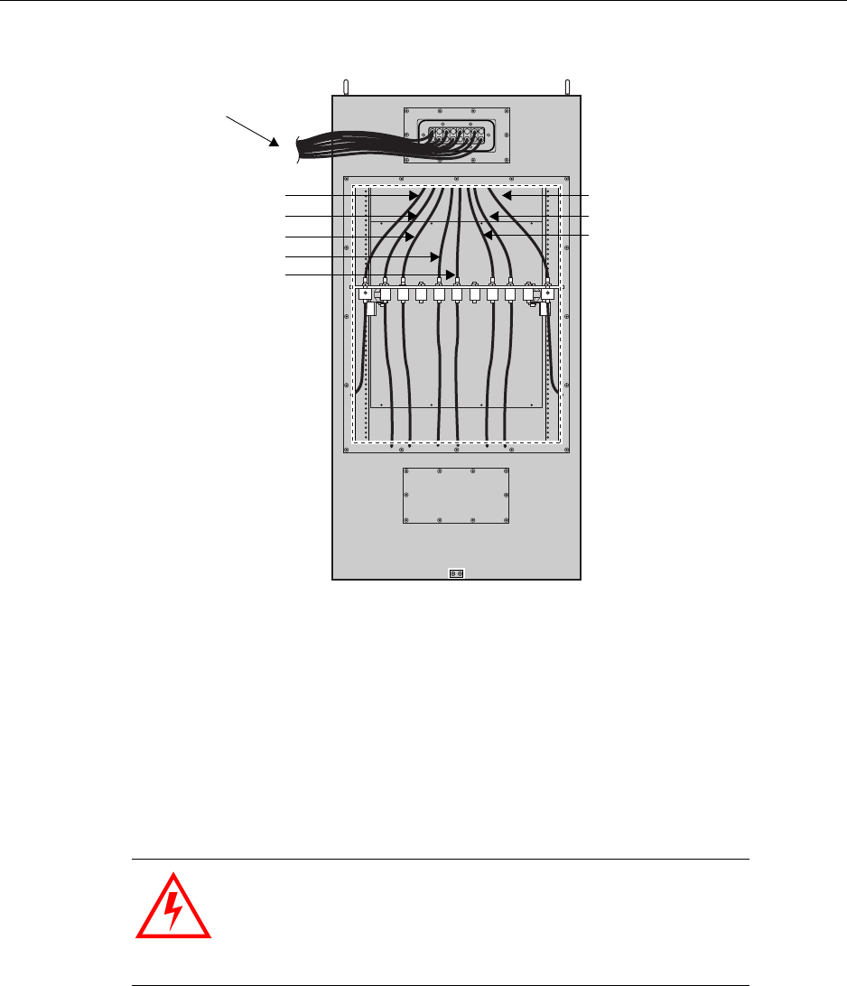
Chapter 6 ● Connecting antennas
100 Release 2.0, 910056 Rev01d
5. Retrieve the 16 tamper-proof screws and rubber washers that you set aside when removing the panel.
6. Ensure the access panel is undamaged:
• Examine the inside edge of the access panel. The gasket on the inside edge must be intact to ensure
a proper seal.
• A spacing washer must be embedded in the gasket for each screw.
7. Position the surge protection access panel and screw in the top middle screw by hand.
Be sure to thread the rubber sealing washer on the screw shank before inserting it in the access panel
screw hole.
8. Start the remaining 15 screws (with washers) by hand. Install them loosely before tightening any one of
them.
WARNING
Screws should be started by hand. It is possible to damage the
thread in the cabinet if you use hand tool or a power tool.
Damaged threads must be repaired or the cabinet will be
improperly sealed and the IP-RN 8000 can be damaged. Use a
thread tapping set to fixed damaged threads.
RF and GPS antennas
Secondary GPS
leading to external
surge suppression equipment
Gamma sector RX1
Gamma sector TX/RX0
Beta sector RX1
Beta sector TX/RX0
Primary GPS
Alpha sector TX/RX0
Alpha sector RX1
Rear view - 6 RF/2 GPS cable configuration

Connecting GPS and RF antennas
IP-RN 8000 Installation & Commissioning Guide 101
9. Use a torque wrench with a 5/32 inch tamper-resistant hex drive bit set to 18 inch-pounds to tighten all
screws evenly.
10. Connect all antenna cables to the proper external antennas/surge protection equipment.
The connections are typically N-type and require a 13/16 inch open ended wrench.
Tighten connections snugly. Do not overtighten.
This procedure is complete. Go to Understanding the module installation process on page 104.
WARNING
If access panels screws are not tightened with the correct torque,
electronic interface may occur causing equipment malfunction.
CAUTION
All external antenna cables exiting the Rox System cabinet seal
must be connected to an external surge suppression system, even
if the cables are not used. Failure to connect unused cables to a
surge suppression system leaves them open to lightning strikes,
which could damage the IP-RN 8000.

Chapter 6 ● Connecting antennas
102 Release 2.0, 910056 Rev01d