CommScope Technologies 800002-1 Licensed Base Station User Manual IP RN 8000 I C Guide
Airvana, LP Licensed Base Station IP RN 8000 I C Guide
Contents
- 1. Manual 1
- 2. Manual 2
Manual 2

IP-RN 8000 Installation & Commissioning Guide 103
Chapter 7
Installing modules
About this chapter
This chapter describes how to install all modules and contains these sections:
•Understanding the module installation process on page 104
•Installing a Power Amplifier on page 105
•Installing a Radio Module on page 108
•Connecting the RM to the PA with the RF cable on page 111
•Connecting the Sector Radio Kit to the Antenna Interface Unit on page 113
•Installing a Timing Frequency Unit on page 116
•Installing a Base Input Output/System Controller on page 119
•Installing a 1xDOM on page 122
WRIST
STRAP
Wear an ESD strap when handling IP-RN 8000 modules.

Chapter 7 ● Installing modules
104 Release 2.0, 910056 Rev01d
Understanding the module installation process
This process explains all steps and procedures to follow when installing modules into the cabinet.
1. Installing Sector Radio Kit(s)
These procedures explain how to install the two modules in a Sector Radio Kit. Repeat the procedures
in this section for each sector in your installation. Typical installations support three sectors, but one or
two sector installations are possible. In addition, several cable connections need to be made involving
the Radio Module, the Power Amplifier module and the Antenna Interface Unit for each sector. Follow
these steps for each Sector Radio Kit you install:
a. See Installing a Power Amplifier on page 105.
b. See Installing a Radio Module on page 108.
c. See Connecting the RM to the PA with the RF cable on page 111.
d. See Connecting the Sector Radio Kit to the Antenna Interface Unit on page 113.
2. Installing Digital Module Kit(s)
These procedures explain how to install the three modules in a Digital Module Kit.
• If you are installing a non-redundant node, follow these procedures once for the primary Digital
Module Kit.
• For redundant installations, follow these procedures twice, once for the primary Digital Module Kit
and once for the redundant Digital Module Kit.
a. See Installing a Timing Frequency Unit on page 116.
b. See Installing a Base Input Output/System Controller on page 119.
c. See Installing a 1xDOM on page 122.
This procedure is complete. You must power the system on. Go to Powering the node on page 126.
Installing a Power Amplifier
IP-RN 8000 Installation & Commissioning Guide 105
Installing a Power Amplifier
This procedure explains how to install a Power Amplifier (PA) module.
Be sure you have read and understood Understanding the module installation process on page 104 before
continuing.
Requirements
• ESD wrist strap
• Slotted screwdriver
WARNING
The PA weighs 22 pounds (10 kg). To avoid injury, use both
hands when handling. Hold the module handle with one hand and
place the other hand under the bottom module slide.
WRIST
STRAP
Wear an ESD strap and plug it into the ESD jack in the AIU when
handling modules or equipment damage can occur. See Figure 9
on page 18.
CAUTION
Ensure that you install the PA module into the proper slot (either
slot 1 top part, slot 5 top part, or slot 9 top part). Installation into a
slot reserved for a different module type can cause equipment
damage.
Chapter 7 ● Installing modules
106 Release 2.0, 910056 Rev01d
Procedure
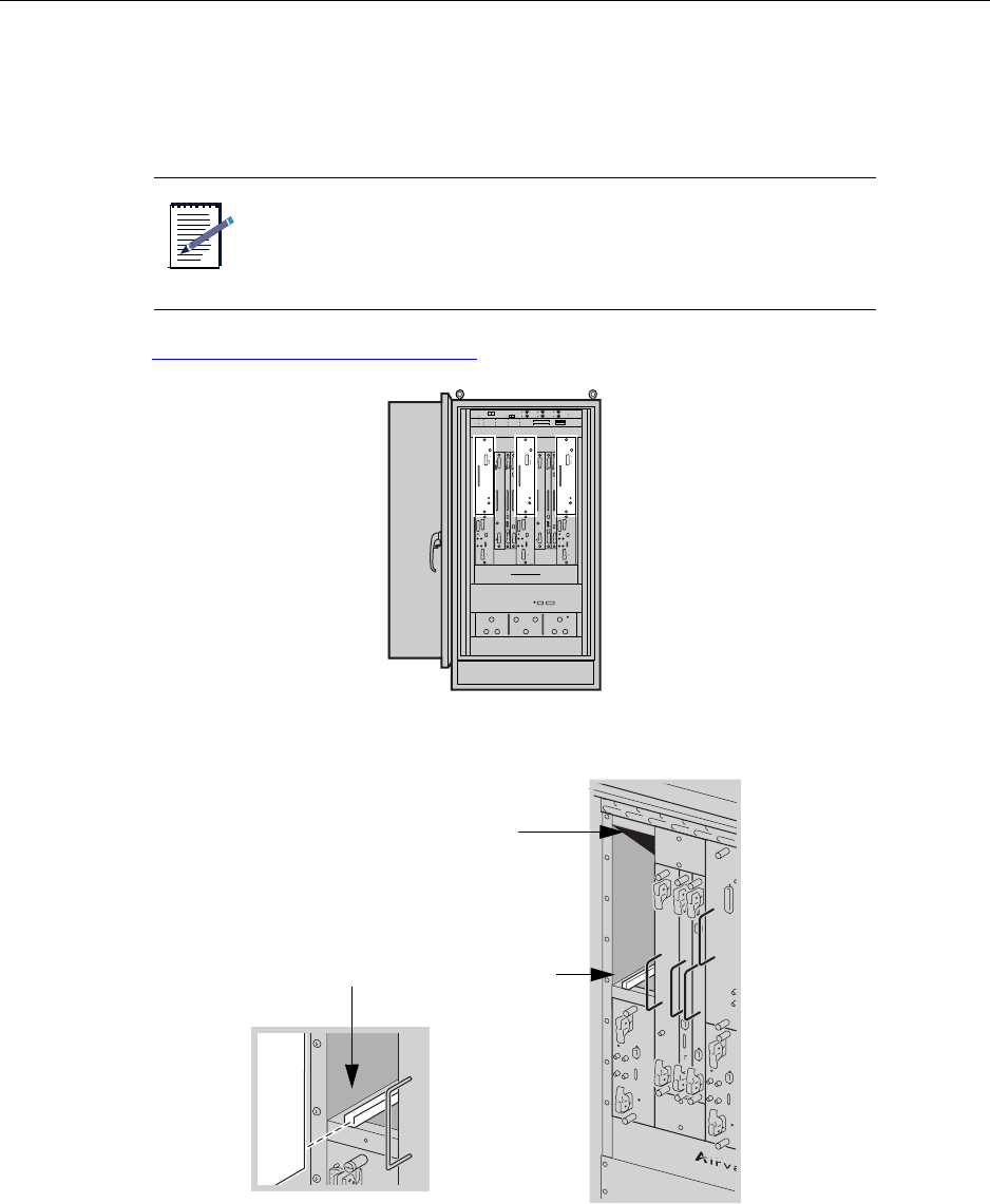
1. Locate the slot into which you will install the PA module.
The PA installs in the top part of slots 1, 5, and 9.
See Understanding module slot numbering on page 11 for more information.
2. Align the PA with the module guides in the top and bottom of the slot of the appropriate sector.
3. Use the module handle to push the PA through the module guides and into the slot until you feel it touch
the backplane.
NOTE
PA modules and RM modules pairs are installed in the top and
bottom of the same vertical module slot.
Top module guide
Bottom module guide
Installing a Power Amplifier
IP-RN 8000 Installation & Commissioning Guide 107
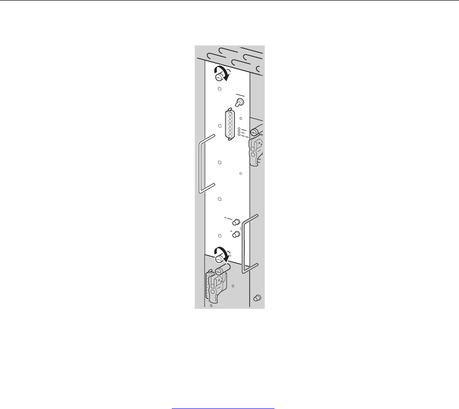
4. Hand tighten the top and bottom captive screws.
5. Use a slotted screwdriver to tighten the two captive screws to secure the PA into the chassis.
Tighten screws snugly, but do not overtighten them or you might strip the threads.
This procedure is complete. Go to Installing a Radio Module on page 108.
Chapter 7 ● Installing modules
108 Release 2.0, 910056 Rev01d
Installing a Radio Module
This procedure explains how to install a Radio Module (RM).
Be sure you have read and understood Understanding the module installation process on page 104 before
continuing.
Requirements
•ESD wrist strap
• Slotted screwdriver
Procedure
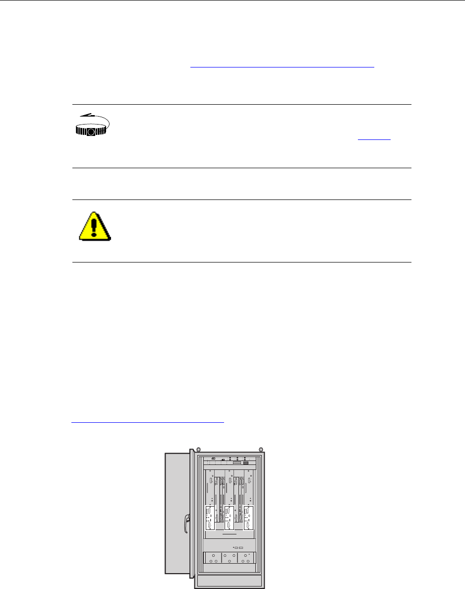
1. Locate the slot into which you will install the RM module.
The RM installs in the bottom part of slots 1, 5, and 9.
See Understanding module slot numbering on page 11 for more information.
WRIST
STRAP
Wear an ESD strap and plug it into the ESD jack in the AIU when
handling modules or equipment damage can occur. See Figure 9
on page 18.
CAUTION
Ensure that you install the RM module into the proper slot (either
slot 1 bottom part, slot 5 bottom part, or slot 9 bottom part).
Installation into a slot reserved for a different module type can
cause equipment damage.
Installing a Radio Module
IP-RN 8000 Installation & Commissioning Guide 109
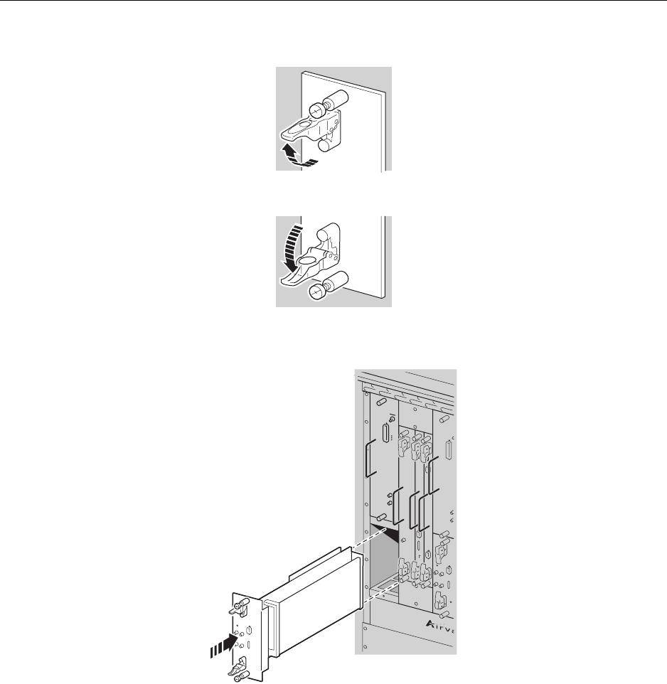
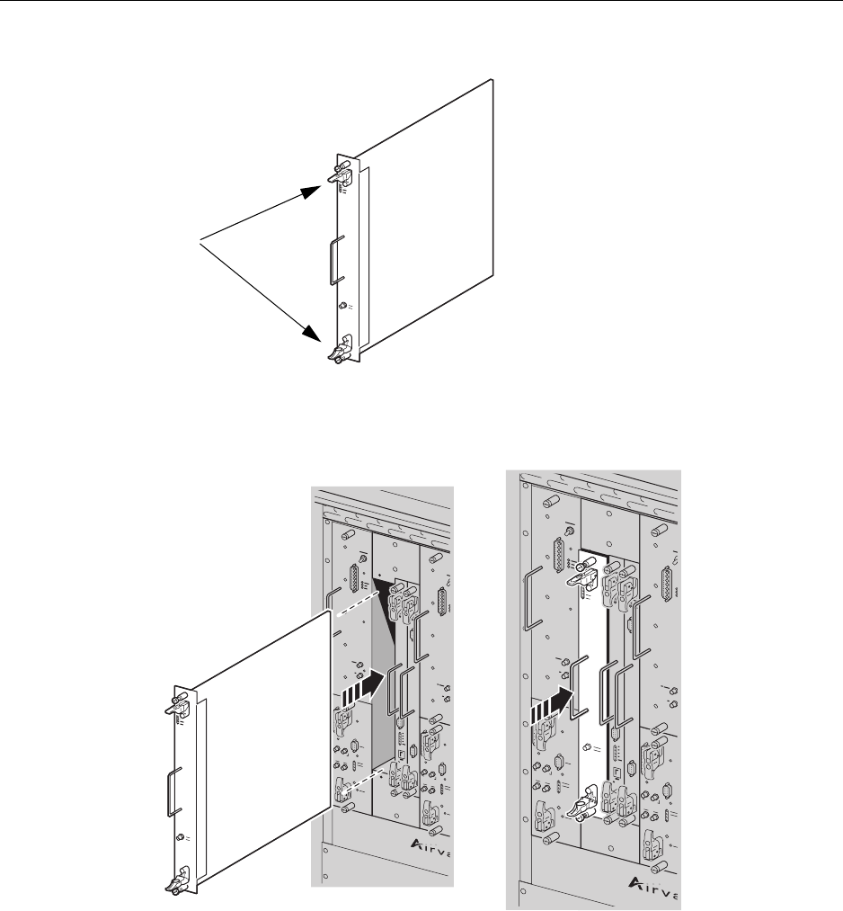
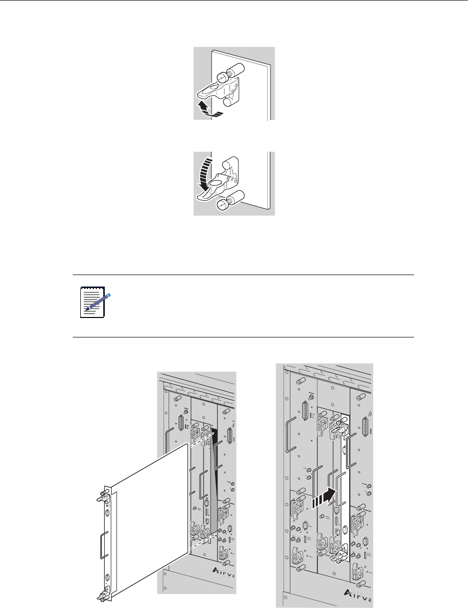
2. Open the top and bottom latches on the RM module faceplate.
3. Align the RM with the module guides in the top and bottom of the slot of the appropriate sector.
4. Push the RM into the slot until you feel it touch the backplane.
Chapter 7 ● Installing modules
110 Release 2.0, 910056 Rev01d
5. Simultaneously, slowly close the top and bottom latches.
As you close the latches, the RM module is drawn snugly into the chassis. Be sure the RM faceplate
does not overlap the PA module. An overlap prevents proper module seating.
6. Hand tighten the top and bottom captive screws.
7. Use a slotted screwdriver to tighten the two captive screws to secure the RM into the chassis.
Tighten screws snugly, but do not overtighten them or you might strip the threads.
This procedure is complete. Go to Connecting the RM to the PA with the RF cable on page 111.
Connecting the RM to the PA with the RF cable
IP-RN 8000 Installation & Commissioning Guide 111
Connecting the RM to the PA with the RF cable
The transmit signal generated in the RM is sent to the PA for amplification before being transmitted. This
procedure explains how to connect the RF port on the RM to the RF port on the PA module using an external
cable provided by Airvana for the sector.
Be sure you have read and understood Understanding the module installation process on page 104 before
continuing.
Requirements
• ESD wrist strap
• Slotted screwdriver
Procedure
1. Retrieve the RF cable for the sector.
The cable is shipped with the modules and is labeled with its part number: 600334.
2. Examine the cable to determine which end is connected to the RM and which is connected to the PA.
The cable has a natural curve to it that makes it easy to install because it makes both connectors face the
same way. However, you have to be sure the right cable ends are connected to the RM and to the PA. So,
hold the cable in place and compare the cable connectors to the connectors on the RM and PA modules.
If the connectors do not fit, reverse the cable 180 degrees and the connectors should fit.
WRIST
STRAP
Wear an ESD strap and plug it into the ESD jack in the AIU when
performing this procedure or equipment damage can occur. See
Figure 9 on page 18.
Chapter 7 ● Installing modules
112 Release 2.0, 910056 Rev01d
3. Gently press one end of the cable to the PA’s RF connector.
4. Gently press the other end of the cable to the RM RF connector.
5. Use the small slotted screwdriver to tighten both screws on both connectors to secure the ends of the
cable into the module connectors.
Tighten snugly but do no over tighten or you can strip the threads.
This procedure is complete. Go to Connecting the Sector Radio Kit to the Antenna Interface Unit on
page 113.
PA
RM
PA RF connector
RF cable
RM RF connector

Connecting the Sector Radio Kit to the Antenna Interface Unit
IP-RN 8000 Installation & Commissioning Guide 113
Connecting the Sector Radio Kit to the Antenna Interface
Unit
This procedure explains how to connect the transmit and receive signals on the Antenna Interface Unit
(AIU) to the Radio Module (RM) and to the Power Amplifier (PA) module for a single sector. The two AIU
receive signals (RX0 and RX 1) are connected to the RM module and the single AIU transmit (TX) signal is
connected to the PA module.
Be sure you have read and understood Understanding the module installation process on page 104 before
continuing.
Requirements
• ESD wrist strap
• Six cable ties
• 13/16 inch open ended torque wrench
• 5/16 inch open ended torque wrench
Procedure
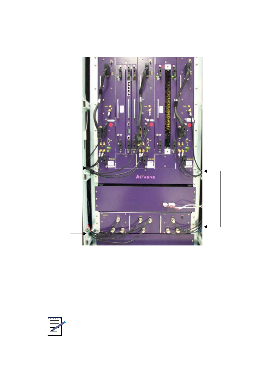
1. Examine the AIU.
The cabinet is shipped with nine cables attached, three cables for each the sector.
Each cable is labeled with its sector (alpha, beta, or gamma) and its use (TX, RX0, or RX1).
2. for each sector, tie the three cables into a bunch with one cable tie near the AIU, and the other cable tie
about two feet short of the other end.
WRIST
STRAP
Wear an ESD strap and plug it into the ESD jack in the AIU when
performing this procedure or equipment damage can occur. See
Figure 9 on page 18.
Chapter 7 ● Installing modules
114 Release 2.0, 910056 Rev01d
3. For each sector, thread the cable bunch between the cabinet housing and the chassis.
Bring the cable bunch back in front of the modules just above the horizontal cabinet frame piece.
• If you are installing the alpha or beta sector, thread the cable bunch to the left.
• If you are installing the gamma sector, thread the cable bunch to the right.
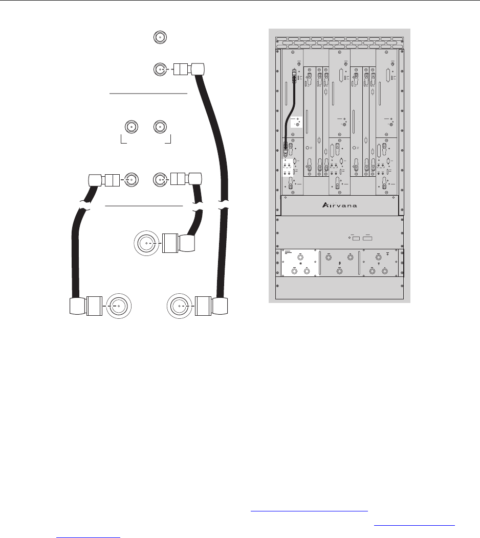
4. For each sector, hand attach the three sector cables to the appropriate connectors on the RM and PA
modules according to their labels.
• Connect the TX cable to the PA TX connector.
• Connect the RX0 cable to the RM RX0 connector.
• Connect the RX1 cable to the RM RX1 connector.
NOTE
• The cables must be attached to the correct connectors
of the equipment will not work. Also, the AIU’s
sector cables must be attached to the correct Sector
Radio Kits.
• The three connectors on the beta sector are in
different locations than is shown in the left half of the
following figure. For the beta sector, the top left
connector is RX0, the top right connector is TX, and
the bottom connector is RX1.
Alpha and beta sector
cables threaded through
cabinet housing
Gamma sector
cables
Connecting the Sector Radio Kit to the Antenna Interface Unit
IP-RN 8000 Installation & Commissioning Guide 115
5. For each sector, tighten all cable connections.
a. Using a 5/16 inch open-ended torque wrench set to seven inch-pounds, tighten the three cable
connections to the RM and PA.
b. Using a 13/16 inch open-ended torque wrench set to seven inch-pounds, tighten the three cable
connections AIU.
6. If you are not deploying any of the three sectors, remove the sector’s cables from the AIU and save
them or dispose of them properly.
This procedure is complete.
• If you have not completed installation of all Sector Radio Kits in this node, you must repeat these
procedures for the next Sector Radio Kit. go to Installing a Power Amplifier on page 105.
• If you have completed installation of all Sector Radio Kits in this node, go to Installing a Timing
Frequency Unit on page 116.
Sample
RX0 RX1
RX0 RX1
TX Sample
TX
RX1
RX0 TX
PA module
RM module
AUI
Chapter 7 ● Installing modules
116 Release 2.0, 910056 Rev01d
Installing a Timing Frequency Unit
This procedure explains how to install a Timing Frequency Unit (TFU) module.
Be sure you have read and understood Understanding the module installation process on page 104 before
continuing.
Requirements
•ESD wrist strap
• Slotted screwdriver
Procedure
1. Locate the slot into which you will install the TFU module.
The primary TFU installs in slot 2. The redundant TFU installs in slot 6.
See Understanding module slot numbering on page 11 for more information.
WRIST
STRAP
Wear an ESD strap and plug it into the ESD jack in the AIU when
handling modules or equipment damage can occur. See Figure 9
on page 18.
CAUTION
Ensure that you install the TFU module into the proper slot (either
slot 2 or slot 6). Installation into a slot reserved for a different
module type can cause equipment damage.
Installing a Timing Frequency Unit
IP-RN 8000 Installation & Commissioning Guide 117
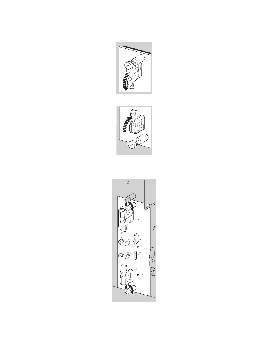
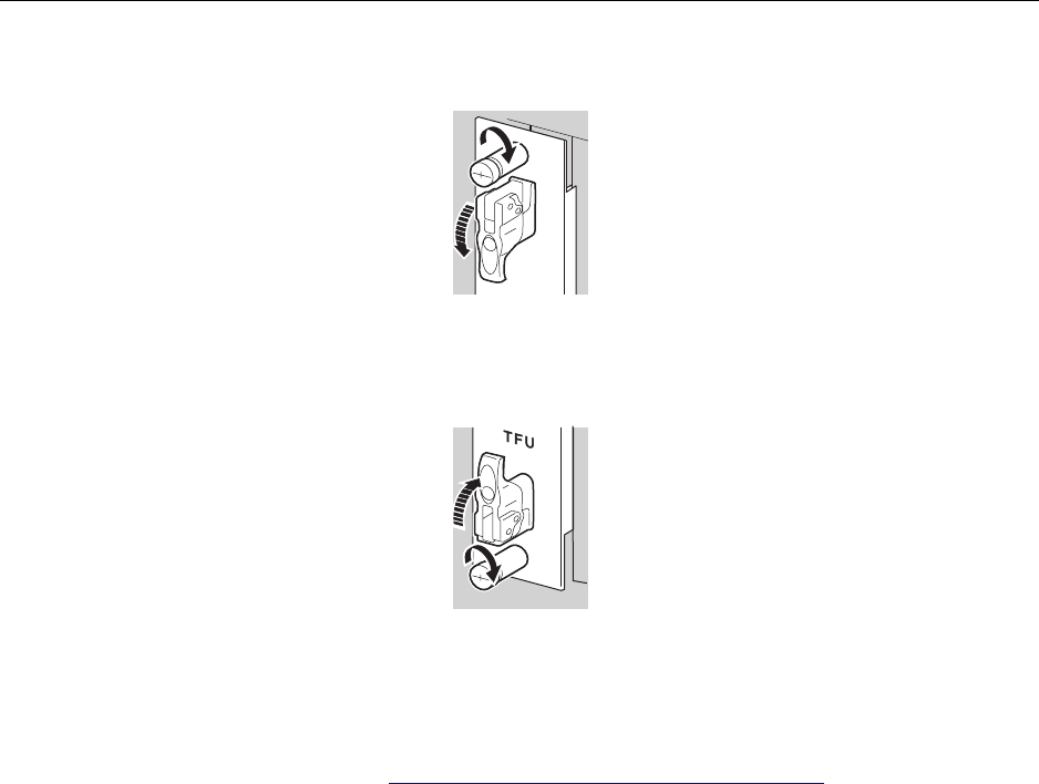
2. Open the top and bottom latches on the TFU module faceplate.
3. Align the TFU module with the module guides in the top and bottom of the appropriate slot and gently
push the TFU into the slot until you feel it touch the backplane.
TFU
Open latches
TFU
Chapter 7 ● Installing modules
118 Release 2.0, 910056 Rev01d
4. Simultaneously, close the top and bottom latches and hand tighten the top and bottom captive screws.
5. Use a slotted screwdriver to tighten the two captive screws to secure the TFU module into the chassis.
Tighten screws snugly, but do not overtighten them or you might strip the threads.
This procedure is complete. Go to Installing a Base Input Output/System Controller on page 119.
Installing a Base Input Output/System Controller
IP-RN 8000 Installation & Commissioning Guide 119
Installing a Base Input Output/System Controller
This procedure explains how to install a Base Input Output/System Controller (BIO/SC) module.
Be sure you have read and understood Understanding the module installation process on page 104 before
continuing.
Requirements
• ESD wrist strap
• Slotted screwdriver
Procedure
1. Identify the slot in which you will install the BIO/SC module.
The primary BIO/SC installs in slot 3. The redundant BIO/SC installs in slot 7.
See Understanding module slot numbering on page 11 for more information.
WRIST
STRAP
Wear an ESD strap and plug it into the ESD jack in the AIU when
handling modules or equipment damage can occur. See Figure 9
on page 18.
CAUTION
Ensure that you install the BIO/SC module into the proper slot
(either slot 3 or slot 7). Installation into a slot reserved for a
different module type can cause equipment damage.
Chapter 7 ● Installing modules
120 Release 2.0, 910056 Rev01d
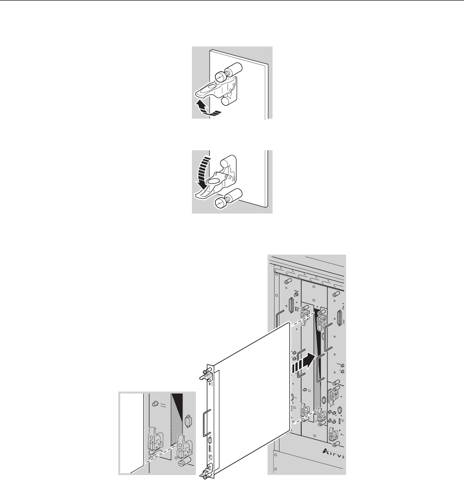
2. Open the top and bottom latches on the BIO/SC module faceplate.
3. Align the BIO/SC with the module guides in the appropriate slot.
BIO/SC
Installing a Base Input Output/System Controller
IP-RN 8000 Installation & Commissioning Guide 121
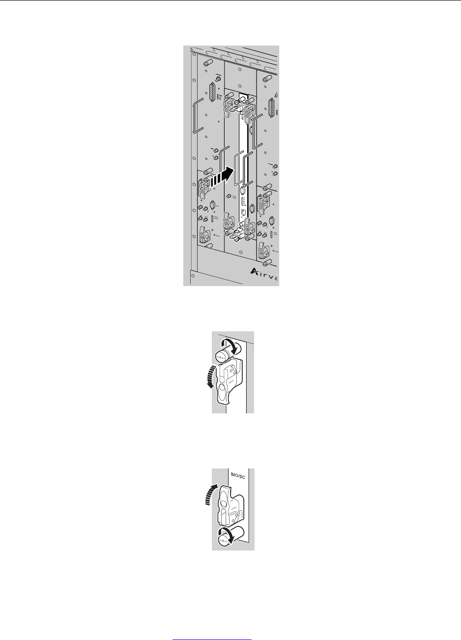
4. Gently push the BIO/SC until it touches the backplane.
5. Simultaneously, close the latches and hand tighten the top and bottom captive screws.
6. Use a slotted screwdriver to tighten the two captive screws to secure the BIO/SC module into the
chassis.
Tighten screws snugly. Do not overtighten them or you might strip the threads.
This procedure is complete. Go to Installing a 1xDOM on page 122.

Chapter 7 ● Installing modules
122 Release 2.0, 910056 Rev01d
Installing a 1xDOM
This procedure explains how to install a 1xDOM module.
Be sure you have read and understood Understanding the module installation process on page 104 before
continuing.
Requirements
•ESD wrist strap
• Slotted screwdriver
Procedure
1. Identify the slot in which you will install the 1xDOM module.
The primary 1xDOM installs in slot 4. The redundant 1xDOM installs in slot 8.
See Understanding module slot numbering on page 11 for more information.
WRIST
STRAP
Wear an ESD strap and plug it into the ESD jack in the AIU when
handling modules or equipment damage can occur. See Figure 9
on page 18.
CAUTION
Ensure that you install the 1xDOM module into the proper slot
(either slot 4 or slot 8). Installing a 1xDOM module into a slot
reserved for a different module type can cause equipment
damage.
Installing a 1xDOM
IP-RN 8000 Installation & Commissioning Guide 123
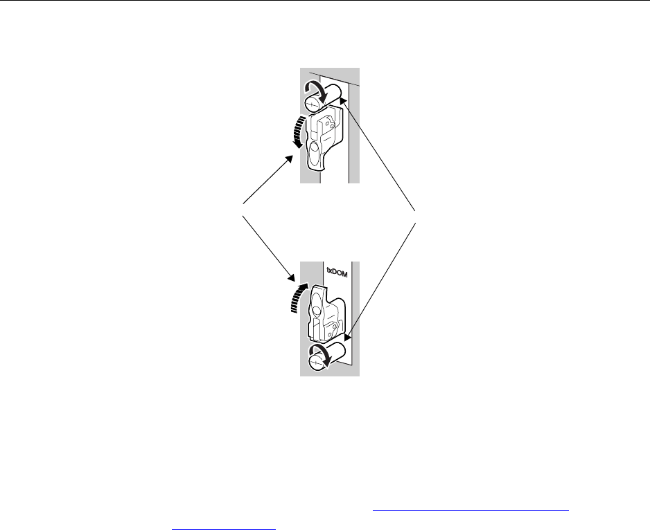
2. Open the top and bottom latches on the 1xDOM module faceplate.
3. Align the 1xDOM with the module guides in the appropriate slot and gently push the module into the
chassis until it touches the backplane.
NOTE
Be careful inserting this module. Take care to avoid collisions
with neighboring modules that could damage either module.
BIO/SC
Chapter 7 ● Installing modules
124 Release 2.0, 910056 Rev01d
4. Simultaneously, close the latches and hand tighten the top and bottom captive screws.
5. Use a slotted screwdriver to tighten the two captive screws to secure the TFU module into the chassis.
Tighten screws snugly, but do not overtighten them or you might strip the threads.
This procedure is complete.
• If you still have a Digital Module Kit to install, go to Installing a Timing Frequency Unit on page 116.
• Otherwise, go to Powering the node on page 126.
Hand tighten
captive screws
Close top and
bottom latches

IP-RN 8000 Installation & Commissioning Guide 125
Chapter 8
Applying primary power
About this chapter
Now that physical installation is complete, this chapter explains how to power on the IP-RN 8000.
This chapter contains a single section:
•Powering the node on page 126.

Chapter 8 ● Applying primary power
126 Release 2.0, 910056 Rev01d
Powering the node
This procedure explains how to power on the IP-RN 8000.
Requirements
None
Procedure
1. Ensure all switches on the Power Distribution Unit (PDU) are flipped to the right and are set to the OFF
position.
For information about the switches on the power distribution unit, see Understanding the Power
Distribution Unit on page 27.
2. Ensure the external circuit breaker controlling power flow on the cabinet’s circuit is closed, enabling
power flow.
3. Flip the Main Power switch to the left to turn power ON.
The Main Power LED lights green.
4. Flip the ALRM switch to the left to power ON the alarm panel.
5. Flip the HXCH switch to the left to turn power ON for the heat exchanger.
As the heat exchanger initializes, LEDs on the heat exchanger on the inside front door blink.
6. Flip the FANS switch to the left to power ON power for the fans.
7. On each PA installed, flip the Power switch up to turn on power for the PA.
8. Flip the CHAS switch to the left to power ON the chassis.
This switch controls power flow to all modules.
Each module’s Power LED illuminates green.
If any of the LEDs do not illuminate as expected, contact Airvana.
This procedure is complete. Go to Understanding the commissioning process on page 128.
WARNING
At this point main power is on but you have not turned on power
to the heat exchanger or the fans. Do not leave the IP-RN 8000 in
this condition for more than a few minutes or over heating could
result. Be sure you continue with the power on procedure without
delay.

IP-RN 8000 Installation & Commissioning Guide 127
Chapter 9
Commissioning process
About this chapter
This chapter explains the main steps to follow when commissioning the IP-RN 8000. This chapter
contains the following sections:
•Understanding the commissioning process on page 128
•Understanding commissioning requirements on page 129

Chapter 9 ● Commissioning process
128 Release 2.0, 910056 Rev01d
Understanding the commissioning process
This process explains the steps to follow when commissioning the IP-RN 8000. Each step consists of one or
more procedures that must be performed in order and to completion before proceeding with the next step.
1. Understanding commissioning
A list of the materials, scripts, and information you need to commission the node.
See Understanding commissioning requirements on page 129.
See Understanding the scripting process on page 146 in Chapter 12, Running the commissioning script.
2. Establishing a serial CLI link to the node
Create a CLI/serial connection from the laptop and the node.
See Understanding the CLI connection process on page 132 in Chapter 10, Establishing CLI
connections.
3. Optionally updating node software
Ensure the node is running the correct software release and, if necessary, update the software release.
See Understanding the software update process on page 140 in Chapter 11, Updating node software.
4. Running the commissioning script
Configure the node to the normal operating configuration by running the commissioning script provided
by the network planner.
See Running the commissioning script on page 145 in Chapter 12, Running the commissioning script.
5. Performing backhaul loopback tests
Reboot the node to enter diagnostics mode and perform backhaul loopback tests.
See Chapter 13, Loopback testing backhaul links
6. Measuring and calibrating transmit power
See Understanding the transmit power calibration process on page 170 in Chapter 14, Calibrating
transmit power.
7. Completing commissioning
Ensure the node is operational and prepare the cell site for the technician’s departure.
See Understanding the commissioning completion process on page 188 in Chapter 15, Completing
commissioning.
This procedure is complete. Commissioning is complete. This is the end of the installation and
commissioning process.

Understanding commissioning requirements
IP-RN 8000 Installation & Commissioning Guide 129
Understanding commissioning requirements
Requirements
Installation must be complete
Commissioning cannot be performed until installation is complete. See Understanding installation and
commissioning on page 40.
Other requirements
Commissioning requires the following:
• A laptop running at least Microsoft Windows 98
• Terminal emulation software, such as HyperTerminal
• Serial cable with male DB-9 connector for attaching to the female DB-9 on the BIO/SC side and a
connector on the laptop side that is correct or the laptop’s serial port
For information on the DB-9 pin-out, see Table 35 on page 196.
• The commissioning script must have been created by network planning personnel and must have been
provided to the field technician.
The commissioning script comprehensively configures the node for normal operations.
• Power meter to test and set RF transmission power during commissioning with connector/adapter
appropriate for the antenna cables exiting the Rox System cabinet seal.
• 30 dB attenuator pad 30 dB attenuator pad with connector appropriate for antenna jumper cable rated
for a maximum of 50 watts
• A power splitter to split the transmit signal for use by the power meter and the AT, with appropriate
cables and connector adapters
• 1xEV-DO access terminal (AT)
Software update requirements
If the field technician is going to change the software release running on the node, the following are also
required:
• FTP client software (included with Windows 98 and later operating systems) to transfer the software
release to the node.
The BIO/SC software contains an FTP server that is also used to transfer the release.
• The laptop must have an Ethernet network interface card (NIC).
The software is transferred to the node over the Ethernet.
• A cross-over ethernet cable with standard RJ-45 connectors.
The cross over cable is required to connect the laptop Ethernet port directly to the BIO/SC craft
Ethernet port without going through an Ethernet switch. If you bring an Ethernet switch, then two
straight-through Ethernet cables are also required (laptop to switch, and switch to BIO/SC).
• The technician must know how to configure the IP address of the laptop Ethernet NIC.
IP must be configured on the laptop Ethernet NIC and on the BIO/SC craft Ethernet port in order to use
FTP to transfer the software release from the laptop to the BIO/SC.
• The software release that is transferred on to the node

Chapter 9 ● Commissioning process
130 Release 2.0, 910056 Rev01d

IP-RN 8000 Installation & Commissioning Guide 131
Chapter 10
Establishing CLI connections
About this chapter
This chapter explains how to establish CLI connections with node and contains the following:
•Understanding the CLI connection process on page 132
•Understanding CLI/serial connections on page 132
•Establishing the CLI/serial connection on page 135
•Understanding craft Ethernet connection to the node on page 133
•Configuring IP on the craft Ethernet and laptop on page 137
•Establishing the CLI/telnet/Ethernet connection on page 138

Chapter 10 ● Establishing CLI connections
132 Release 2.0, 910056 Rev01d
Understanding the CLI connection process
This section explains the process for making a CLI connection.
1. Understanding CLI options
See Understanding CLI/serial connections on page 132.
2. Establishing a CLI /serial link with the node
A serial link for CLI node management is created from the laptop to the node.
See Establishing the CLI/serial connection on page 135.
3. Optionally establishing a CLI/telnet/craft Ethernet session with the node.
CLI/telnet/craft Ethernet is required when you need multiple simultaneous CLI sessions with the node.
a. Configuring IP on the craft Ethernet and laptop on page 137
b. Establishing the CLI/telnet/Ethernet connection on page 138
This procedure is complete.
Understanding CLI/serial connections
The command line interface (CLI) enables text-based, command-oriented management of the IP-RN 8000.
The CLI can be accessed in three ways:
• CLI/serial — Direct connection to the craft serial port on the BIO/SC, RM, and TFU module serial craft
ports
• CLI/telnet/craft Ethernet — A laptop’s Ethernet adapter is connected to the craft Ethernet port on the
BIO/SC module, IP is configured on the laptop on the craft Ethernet, and a telnet session provides CLI
access.
• CLI/telnet/backhaul — When the node is fully configured and functional backhaul links, you can telnet
to the node’s node IP address from anyplace on the IP network.
CLI/serial
CLI/serial is the simplest form of CLI connection. It is only available when you are local to the serial port.
This form of CLI connection is required during initial phases of commissioning. For example, you must use
CLI/serial to set the craft Ethernet IP address if you then want to use CLI/telnet/craft Ethernet. You can only
have a single CLI/serial connection to a node at a time when using CLI/serial. CLI/serial connection requires
a cable to link the serial craft port on the network element to a serial port (typically a COM port) on a laptop
or other device. Launch a terminal emulation program on the laptop (such as Hyperterminal) and configure
the communications settings appropriately (see Establishing the CLI/serial connection on page 135).
CLI/serial on redundant systems
CLI/serial connection is made by connecting a laptop running terminal emulation software to the serial port
on the BIO/SC module. Redundant systems have two BIO/SC modules. In almost all cases, you should plug
the serial cable into the active BIO/SC module.
You can tell which BIO/SC module is active by examining the LEDs on the BIO/SC modules. See
Understanding the Base Input Output/System Controller module on page 22.

Understanding craft Ethernet connection to the node
IP-RN 8000 Installation & Commissioning Guide 133
When configuring the node from the active BIO/SC module, all configurations apply to the entire node.
However, there are some cases where you need to plug the serial cable into the serial port on the inactive
BIO/SC module. For example, if the node uses Ethernet backhauls, the only way to loopback test the
Ethernet link associated with the inactive module is to plug the serial cable into the serial port on the inactive
BIO/SC module.
CLI/telnet/craft Ethernet
CLI/telnet/craft Ethernet is made by connecting an Ethernet adapter on your laptop to the Ethernet craft port
on the BIO/SC module, either directly using a cross over cable or through a switch or hub using straight
through cables. You must configure appropriate IP addresses and masks on the BIO/SC Ethernet port (using
CLI/serial) and on the laptop Ethernet port. Then you launch telnet and open a CLI session with the node
using the node IP address or the craft Ethernet IP address.
Because you can open multiple CLI sessions at a time using telnet, this method is required during certain
phases of the commissioning procedure.
CLI/telnet/backhaul
CLI/telnet/backhaul is made through the existing backhaul network. This assumes a normally operating
network with backhaul links that are up and running and IP addressing that is fully configured and correct.
You can open a telnet session with the node’s node IP address from any location support by the IP network
design.
Understanding craft Ethernet connection to the node
The BIO/SC module has two craft ports:
• Female DB-9 for serial connections
• RJ-45 Ethernet
For information about BIO/SC craft ports, see Understanding the Base Input Output/System Controller
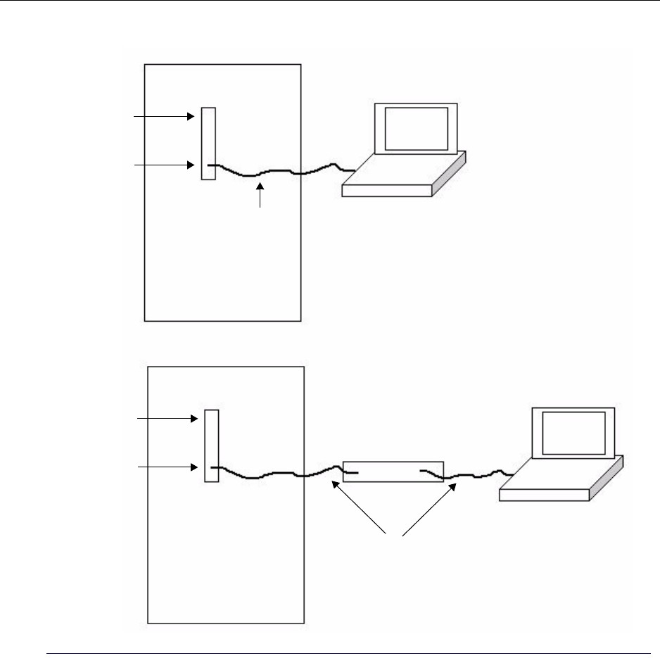
module on page 22. There are two ways to connect a laptop Ethernet to the BIO/SC craft Ethernet (see
Figure 21):
• Directly using a cross-over cable
• Indirectly using an Ethernet switch and two straight-through cables
Chapter 10 ● Establishing CLI connections
134 Release 2.0, 910056 Rev01d
Figure 21 Two craft Ethernet connectivity options
IP-RN 8000
IP-RN 8000
BIO/SC module
Cross-over cable
Craft Ethernet
BIO/SC module
Craft Ethernet
Straight-through cables
Ethernet switch
Establishing the CLI/serial connection
IP-RN 8000 Installation & Commissioning Guide 135
Establishing the CLI/serial connection
This procedure explains how to connect the laptop’s COM port to the active BIO/SC’s craft serial port and
how to start the CLI/serial session. It is assumed the IP-RN 8000 is powered on.
Requirements
• A laptop running at least Microsoft Windows 98
• The laptop must have either sufficient batteries to run throughout the commissioning process or it must
have a power source and appropriate power adapter
• Terminal emulation software, such as Hyperterminal, which comes with Windows
• Serial cable with male DB-9 connector for attaching to the female DB-9 on the BIO/SC side and a
connector on the laptop side that is appropriate for the laptop’s serial port
Procedure
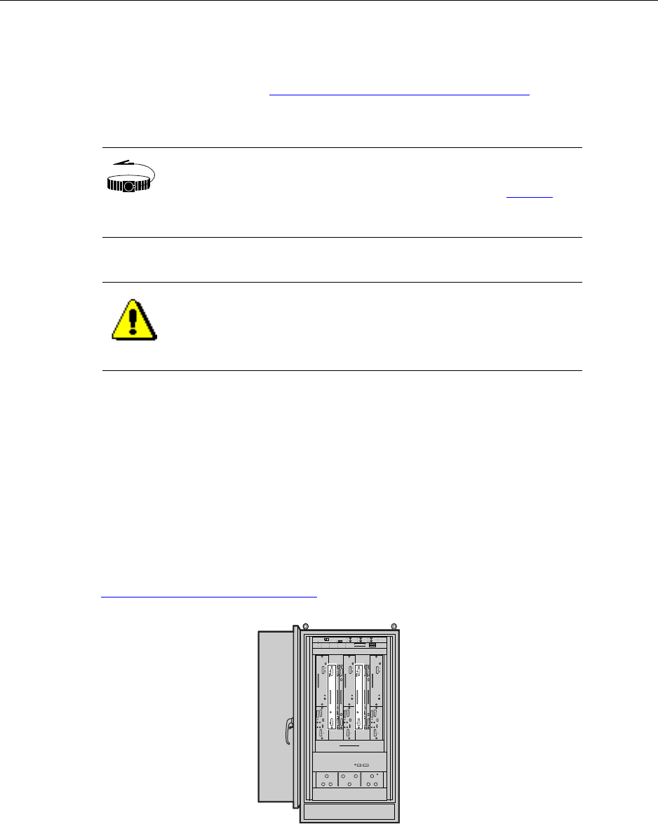
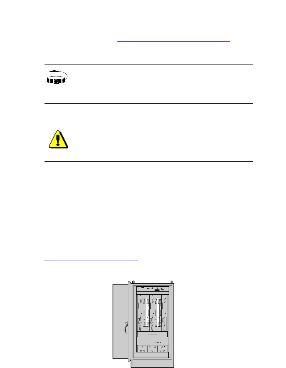
1. Open the PC shelf on the inside of the front door and place the laptop securely on the shelf.
See Opening the PC shelf on page 201.
2. Boot up the laptop.
3. Retrieve the CLI cable.
4. Determine which BIO/SC module is active.
If there is only a single BIO/SC installed, it is installed in slot 3 and is active.
If there are two BIO/SC modules installed, check the ACTIVE LEDs to determine which one is active
and which is standby. See Understanding the Base Input Output/System Controller module on page 22.
Typically the primary BIO/SC module in slot 3 is the active module and the redundant BIO/SC module
in slot 7 is the standby module.
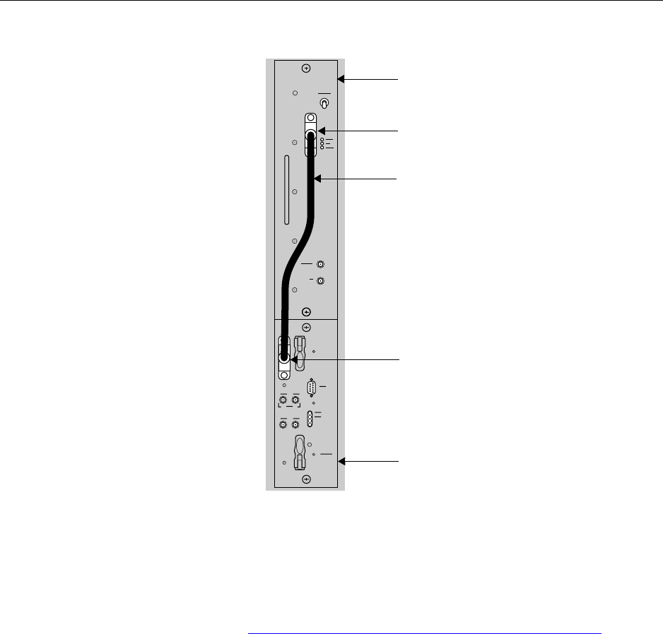
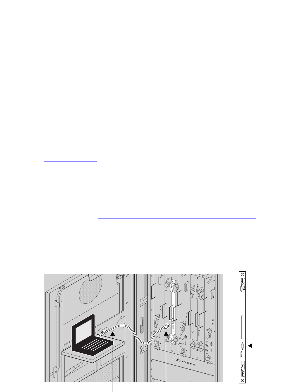
5. Plug the male DB-9 end of the serial cable into the female DB-9 craft port on the active BIO/SC
module.
6. Plug the other end of the serial cable into the COM port of the laptop.
BIO/SC
DB-9
connector
Connect to laptop
COM port
Connect to DB-9 serial port
on active BIO/SC
Chapter 10 ● Establishing CLI connections
136 Release 2.0, 910056 Rev01d
7. Launch the terminal emulation program.
You can use HyperTerminal, which comes with windows, or any terminal emulation program of your
choice.
8. Open a terminal connection as appropriate for the terminal emulation software.
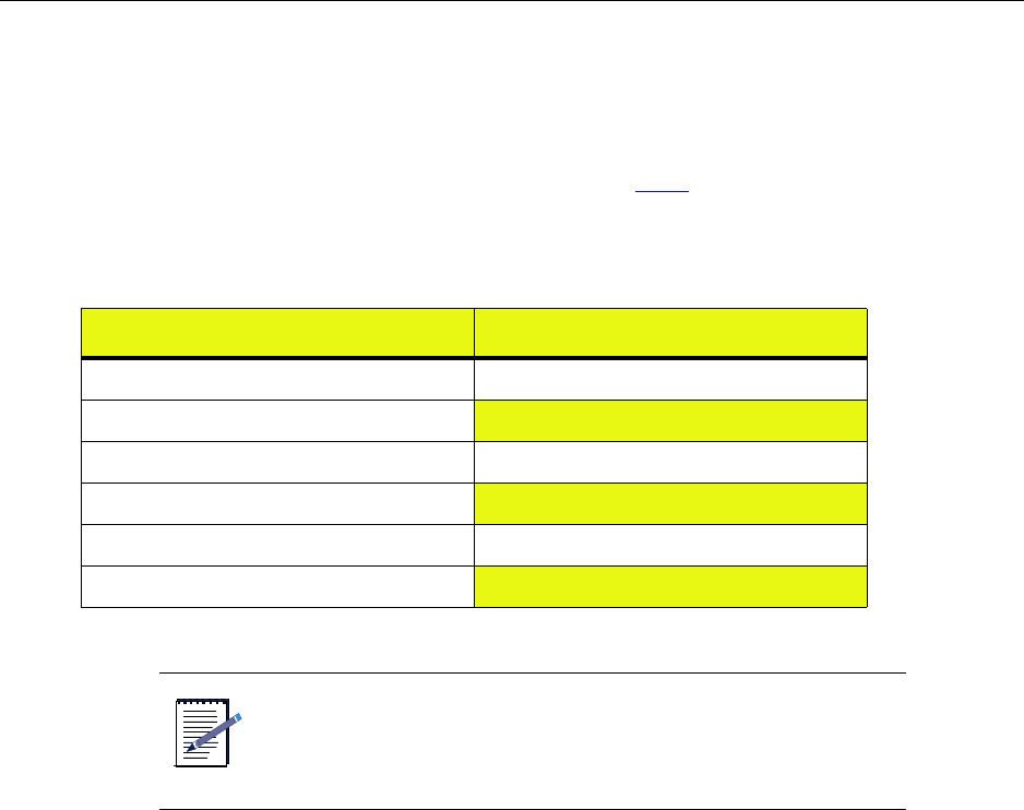
9. Configure the terminal connection parameters as shown in Table .
10. Press <ENTER> on the laptop.
The CLI command prompt displays as follows:
AIRVANA-03>
This procedure is complete.
Table 22 Terminal settings for CLI/serial connection
Setting Value
Terminal emulation type VT220 or VT100
Bits per second (BAUD) 38400
Data bits 8
Parity None
Stop bits 1
Flow control None
NOTE
If you are establishing CLI/serial connection the craft serial ports
on the RM or TFU modules, you must set the Bits per second to
112500.
Configuring IP on the craft Ethernet and laptop
IP-RN 8000 Installation & Commissioning Guide 137
Configuring IP on the craft Ethernet and laptop
This procedure explains how to configure IP addressing so that you can use FTP to transfer the new release
from the laptop Ethernet to the node over the active BIO/SC Ethernet craft port. This procedure requires an
active CLI/serial connection to the active BIO/SC.
1. Enter the following commands to set the IP address on the Ethernet craft port of the active BIO/SC:
AIRVANA-03>enable
AIRVANA-03#configure
AIRVANA-03(config)#interface ethernet1/3/2
AIRVANA-03(config-if)#ip address 10.0.0.1/24
AIRVANA-03(config-if)#no shutdown
AIRVANA-03(config-if)#exit
AIRVANA-03(config)#exit
AIRVANA-03#exit
2. Enter the following IP configuration into the Ethernet network interface card (NIC) on your laptop:
• IP address: 10.0.0.2
• Subnet mask: 255.255.255.0
• Default gateway: no default gateway is required — leave it blank.
This procedure is complete. Go to Establishing the CLI/telnet/Ethernet connection on page 138.
NOTE
• ethernet1/3/2 identifies the craft Ethernet interface on
the BIO/SC in slot 3 as follows: The “1” means this
node. The “3” means slot 3. The “2” means craft
Ethernet.
• This IP address and mask and the IP address and
mask configured in the next step form a subnet. You
can use any two IP addresses that are in the same
subnet.
NOTE
Airvana does not specify the laptop operating system and cannot
specify the exact steps you need to take to configure the IP
information for the Ethernet NIC.

Chapter 10 ● Establishing CLI connections
138 Release 2.0, 910056 Rev01d
Establishing the CLI/telnet/Ethernet connection
This procedure explains how to physically connect the laptop to the node through the craft Ethernet
Requirements
• Either a cross-over RJ-45 Ethernet cable
• Or two straight-through Ethernet RJ-45 cables and an Ethernet switch with a power supply
Procedure
1. Plug one end of your RJ-45 cable into the craft Ethernet port on the active BIO/SC module.
The Active LED is lit on the BIO/SC module. (On non-redundant systems there is only a single BIO/SC
module and it is always active.)
For information about the LEDs on the BIO/SC module, see Understanding the Base Input Output/
System Controller module on page 22.
2. If you are using a cross-over RJ-45 cable and no Ethernet switch to connect the laptop to the node:
a. Plug the free end of the cable into the laptop Ethernet.
b. Skip step 3 and go to step 4.
3. If you are using two straight-through cables and an Ethernet switch to connect the laptop to the node:
a. Connect the free end of the cable into a switch port
b. Connect one end of the second cable into another switch port
c. Connect the free end of the second cable into the laptop Ethernet port
d. Power on the Ethernet switch.
The switch LED for the Ethernet port lights indicating an operational Ethernet link.
4. On the laptop, open a telnet session to the node using the node’s craft Ethernet IP address (or to the IP
address of another Airvana device, for example the IP-RNC 8500 to which this node is homed), as
follows:
a. Open a command prompt window on the laptop by clicking Start ⇒ Run, entering CMD and
clicking OK.
b. At the command prompt in the new command window, type telnet <IPaddress>, where
<IPaddress> is the IP address you configured for the BIO/SC craft Ethernet using the CLI/
serial connection (or the IP address of another Airvana device, such as the management IP address
of an IP-RNC 8500).
The following displays indicating a CLI/telnet session is active:
AIRVANA-03>
This procedure is complete. Go to Updating node software on page 139 or Chapter 12, Running the
commissioning script as appropriate.

IP-RN 8000 Installation & Commissioning Guide 139
Chapter 11
Updating node software
About this chapter
This chapter describes how to check the node’s software release version and optionally update it.
This chapter contains the following sections:
•Understanding the software update process on page 140
•Checking the active release and free disk space on page 140
•Transferring the node software from the laptop to the node on page 142
•Activating the release on page 144

Chapter 11 ● Updating node software
140 Release 2.0, 910056 Rev01d
Understanding the software update process
The process explains how to check the version of the node’s currently executing software release, how to
transfer a new release to the node, and how to reboot the node using the new release.
1. Checking the current release and free disk space
This is optional and may not need to be performed during installation for some nodes. Consult your
network planner.
See Checking the active release and free disk space on page 140.
2. Transferring the new release to the node
The new release is transferred over the IP/Ethernet connection using FTP.
See Transferring the node software from the laptop to the node on page 142.
3. Activating the new release
The node is reset using the new release.
See Activating the release on page 144.
This procedure is complete. This process is complete. Go to Running the commissioning script on page 145.
Checking the active release and free disk space
This procedure explains how to use the CLI to check the currently active software release on the node, how
to check the amount of free disk space on the node, and how to delete files if more free space is needed
before transferring a new release to the node. It is assumed you have an active CLI session. This procedure is
unnecessary if you are not intending to update the node’s software release version.
Requirements
A CLI/serial connection to the node.
See Establishing CLI connections on page 131.
NOTE
The node’s software release version can be updated later from a
centralized location using AirVista or CLI/telnet.

Checking the active release and free disk space
IP-RN 8000 Installation & Commissioning Guide 141
Procedure
1. Enter the show version command as follows:
AIRVANA-03>show version
The CLI output displays the currently executing release. Make note of whether you need to update the
release.
2. Use the shell command to enter the CLI shell as follows:
AIRVANA-03>shell
The following prompt displays:
AIRVANA-03(shell)(disk0:/)>
3. Enter the ls command to check how much free space there is on the node’s disk as follows:
AIRVANA-03(shell)(disk0:/)>ls
The following displays with data values as appropriate for the node. Note the “Free MBytes” at the
bottom. This indicates the amount of free space on the disk.
size date time name
---------- ------ ----- ---------------
32768 May 23 14:43 active/
32768 May 23 14:18 images/
511 May 15 15:23 config.bin
32768 May 23 14:49 logs/
32768 May 20 12:56 backup/
32768 Apr 10 07:52 dcbackup/
524288 May 13 21:18 leofs
Free MBytes 38136
4. If there is less than 30 Mbytes free, use the xrm command as follows to delete all files in the
disk0:/images directory:
AIRVANA-03(shell)(disk0:/)>xrm images
The following displays, indicating the files being deleted from the c:\images directory.
deleting file images/rn8500.2.0.0.tar
deleting file images/version.txt
...
5. Enter the exit command to leave the shell and return to the normal CLI prompt.
The following prompt displays:
AIRVANA-03>
This procedure is complete.

Chapter 11 ● Updating node software
142 Release 2.0, 910056 Rev01d
Transferring the node software from the laptop to the node
This procedure explains how to use FTP to transfer the new software release from the laptop to the node
over the IP/Ethernet connection. The software release must be on the laptop.
Requirements
An CLI/telnet/craft Ethernet connection from the laptop to the node of the BIO/SC craft Ethernet.
• See Configuring IP on the craft Ethernet and laptop on page 137
• See Establishing the CLI/telnet/Ethernet connection on page 138
Procedure
1. On the laptop, open a command line window:
a. Select Start > Run
b. Type cmd in the text box
c. Click the OK button
The command line application window opens and the command prompt displays as follows:
C:\>
2. Launch the Windows FTP client in the command line window by entering the following
C:\>ftp
The following command prompt displays:
ftp>
3. Open an FTP connection with the node by entering the following:
ftp>open 10.0.0.1
The following displays:
Connected to 10.0.0.1:
220 VxWorks (5.4) FTP server ready
User (<IP ADDRESS):(none)):
4. Press the <ENTER> key.
The following displays:
Password required:
NOTE
This procedure requires a working IP connection from the laptop
Ethernet to the BIO/SC craft Ethernet port. It does not actually
require a CLI/telnet connection. Follow both procedures listed
above with the exception of launching the talent session (the
second part of the second procedure).

Transferring the node software from the laptop to the node
IP-RN 8000 Installation & Commissioning Guide 143
5. Press the <Enter> key.
The following displays:
ftp>
6. Enter the following to enable hash mark printing.
ftp>hash
7. Enter the following to change the FTP directory on the node to the images directory:
ftp>cd images
The following displays:
ftp>Hash mark printing On ftp: (2048 bytes/hash mark).
Now, FTP will output a number sign (#) to the DOS FTP command prompt for every 2048 bytes
transferred. This enables you to watch the progress of the file transfer.
8. Enter the following to change the FTP file transfer mode to binary:
ftp>binary
You are now ready to transfer the software release from the laptop to the node.
9. Enter the following to transfer the release from the laptop to the node disk0:/images directory:
ftp>put <path and release filename>
Where <path and release filename> is the complete path and filename for the release on your laptop.
For example, if the release is in the c:\releases\IPRN8000\ directory and if the release filename is
rn.2.0.0.tar, enter the following
ftp>put c:\releases\IPRN8000\rn.2.0.0.tar
FTP displays a long series of hash marks (“###########...) indicating the file transfer is
progressing.
The following displays to indicate a successful file transfer:
(line #): Transfer completed
The release is now on the node in the following directory: disk0:/images
This procedure is complete. Go to Activating the release on page 144

Chapter 11 ● Updating node software
144 Release 2.0, 910056 Rev01d
Activating the release
This procedure explains how to use the activate command to make the release you just transferred to the
node the current running release. This procedure assumes you have an active CLI/serial connection to the
active BIO/SC module.
1. Enter the following commands to enter Global Configuration Mode in the CLI:
AIRVANA-03>enable
AIRVANA-03#configure
2. Enter the following command to reset the node using the software release you just transferred to the
node:
AIRVANA-03(config)#activate image <release> reboot
Where <release> is the filename of the release that was transferred to the node.
For example:
AIRVANA-03(config)#activate image rn.2.0.0.tar reboot
This command:
• Copies the previous release (rn.2.0.0.tar) into the disk0:/backup directory
• Extracts the rn.2.0.0.0.tar release into the disk0:/active directory
• Reboots the node using the 2.0.0.0 release
This step takes about four minutes to complete.
This procedure is complete. Go to Chapter 12, Running the commissioning script.
NOTE
If you also need to update the boot code, add the updateboot
switch to the command as follows:
activate image <release> reboot updateboot.

IP-RN 8000 Installation & Commissioning Guide 145
Chapter 12
Running the commissioning script
About this chapter
This chapter describes how to run the commissioning script to configure the node for normal
operations. This chapter contains the following sections:
•Understanding the scripting process on page 146
•Initializing the node to receive a file with kermit on page 147
•Transmitting a script from a laptop to the network element on page 148
•Verifying the script file is on the node on page 154
•Running the script on page 155

Chapter 12 ● Running the commissioning script
146 Release 2.0, 910056 Rev01d
Understanding the scripting process
This process explains all steps and procedures to follow when transferring a script to a node and running the
script.
1. Understanding scripts and script transfer options
This procedure explains how to use the kermit protocol over a serial link to the node to transfer the
script file to the node. This is the simplest method. However, you can also use FTP to the node if you
have an IP connection.
See Understanding scripts on page 146.
See Understanding script transfer options on page 147.
2. Initializing the node to receive the script file with kermit
Using CLI, enter the node shell and prepare the node to receive the file from the laptop over the serial
connection using the kermit protocol.
See Initializing the node to receive a file with kermit on page 147.
3. Initializing the laptop and transmitting the script file with kermit
Launch HyperTerminal and send the file using the kermit protocol.
See Transmitting a script from a laptop to the network element on page 148
4. Verifying the script file is on the node
Verify the script file was transferred to the node.
See Verifying the script file is on the node on page 154.
5. Running the script file on the node
Run the script file on the node to update the node’s operating configuration
See Running the script on page 155.
This procedure is complete.
Understanding scripts
Scripts are collections of CLI commands stored in a text file. The script is created by centralized network
planners and provided to the installer/commissioner. The script is transferred to the node using
Hyperterminal (or any application that supports the kermit file transfer protocol) or FTP and executed with
the CLI copy command to update the node’s operating configuration. The write command should occur
at the beginning of the script to copy the current configuration to disk. If there is an error during script
execution and you reboot the network element, the configuration is restored.

Understanding script transfer options
IP-RN 8000 Installation & Commissioning Guide 147
Understanding script transfer options
There are two ways files can be transferred to a node:
• Through the BIO/SC craft serial port using the kermit protocol
• Through the craft Ethernet or the backhaul using FTP
There are typically two types of files you need to transfer to the node:
• A software release for upgrading node operating software
• A script file for updating the operating configuration of the node
Which method is used depends on the following considerations:
Serial link requires less configuration
The kermit over the serial connection requires less configuration than FTP. No connection to the craft
Ethernet is required, and no configuration of IP addresses is required. All that is required is a serial cable
connecting the laptop COM port to the BIO/SC craft serial port. However, if you already have an IP
connection to the node, then FTP is a straightforward and convenient way to transfer either script files or
software releases to the node.
Remote file transfer requires FTP
The serial link can only be used if you are at the same physical location as the node. If you are not at the
same physical location, you can transfer files using FTP.
Use FTP to transfer large files such as software releases
Large files such as software releases should be transferred to the node using FTP through the craft Ethernet
or through the backhaul because it can take hours to transfer such large files through the serial port.
Initializing the node to receive a file with kermit
This procedure explains how to initialize the node to receive a file transmitted from a laptop connected over
a serial connection using the kermit protocol.
The script file must be transferred to the node before it can be executed on the node.
This procedure assumes you have an operational CLI connection to the active BIO/SC module. For
information, see Establishing the CLI/serial connection on page 135.
You must also have the script file on your laptop.
1. Use shell to change to the command line shell as follows:
AIRVANA-03>shell
The following prompt displays:
AIRVANA-03(shell)(disk0:/)>
2. Use ls to check whether the config directory exists:
AIRVANA-03(shell)(disk0:/)>ls

Chapter 12 ● Running the commissioning script
148 Release 2.0, 910056 Rev01d
3. Examine the output from the ls command. If there is no config directory, create the config
directory by entering the following:
AIRVANA-03(shell)(disk0:/)>mkdir config
4. Move to the config directory by entering the following:
AIRVANA-03(shell)(disk0:/)>cd config
The following displays:
AIRVANA-03(shell)(disk0:config)>
5. Prepare the node to use kermit to receive the file by entering the following:
AIRVANA-03(shell)(disk0:config)>kermit receive <filename>
Where <filename> is the name you want the script file to have after it is received on the node
through kermit. This is not necessarily the same file name that the script file has on the laptop.
The CLI is now locked waiting to receive a file. Now you must prepare the laptop and transmit the
script file using kermit.
This procedure is complete. Go to Transmitting a script from a laptop to the network element on page 148.
Transmitting a script from a laptop to the network element
This procedure explains how to transmit a script file from the laptop to a node that is already initialized to
receive the file using kermit over the serial connection using kermit.
1. Launch HyperTerminal.
On the laptop on, click Windows Start ⇒Programs ⇒ Accessories ⇒ Communications ⇒
HyperTerminal.
NOTE
The click sequence to launch Hyperterminal is different on
different versions of Windows.
Transmitting a script from a laptop to the network element
IP-RN 8000 Installation & Commissioning Guide 149
The following splash screen displays while HyperTerminal launches:
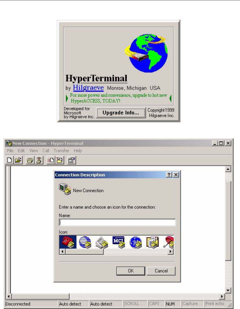
After a few seconds, the splash screen is replaced by the following:
Chapter 12 ● Running the commissioning script
150 Release 2.0, 910056 Rev01d
2. Enter a name for the connection, for example: ScriptFileTransferOverSerial and click OK.
By entering a name for this connection, you can optionally save the connection and open it later without
having to re-enter the connection parameters.
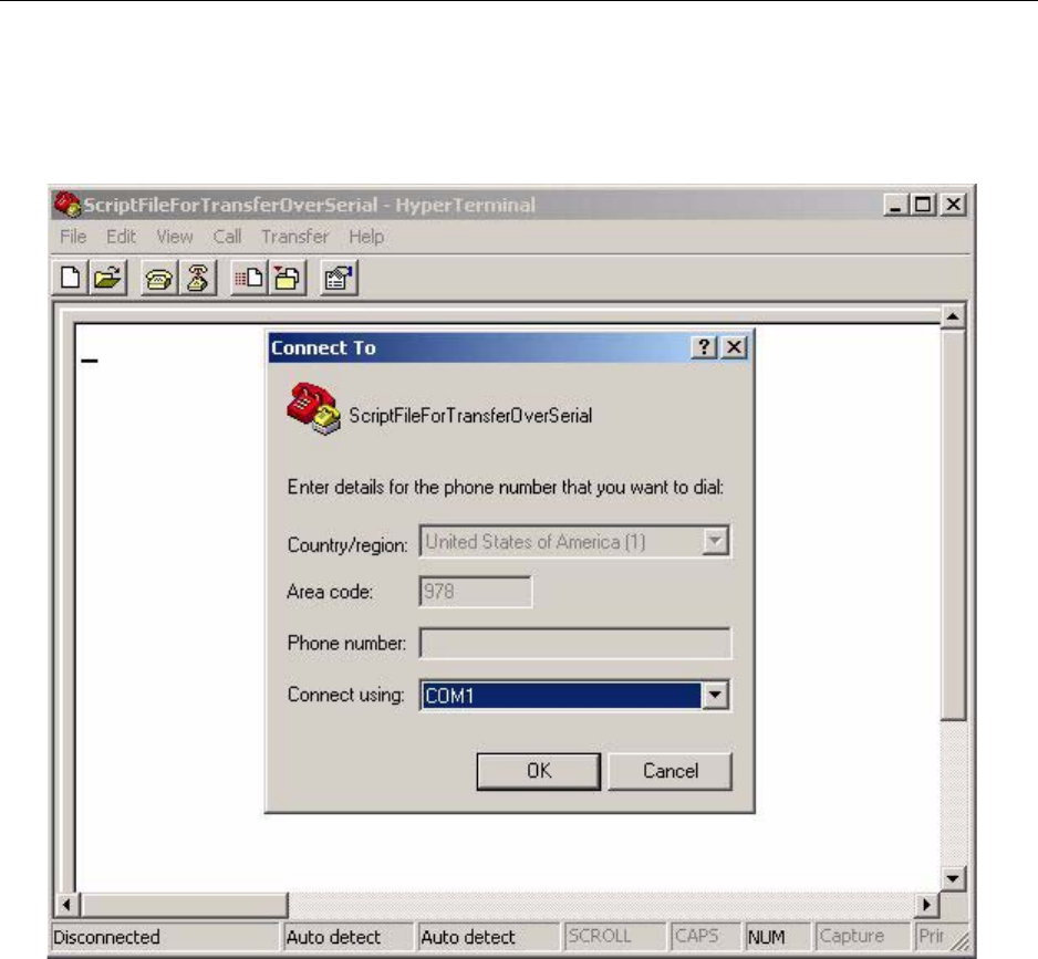
After clicking OK, the following window displays:
3. Ensure the proper COM port is selected in the Connect using pull down selection list.
The correct COM port is the one to which you have connected the serial cable.
Transmitting a script from a laptop to the network element
IP-RN 8000 Installation & Commissioning Guide 151
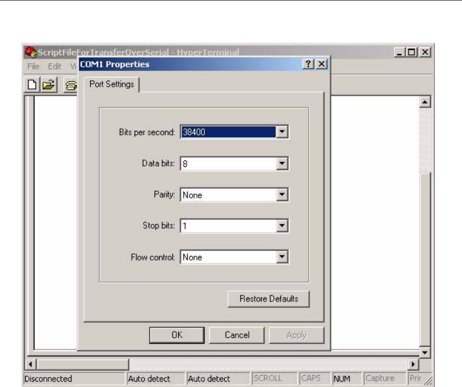
4. Click OK and the following COM1 properties window displays:
a. In the Bits per second pull down selection list, select 38400.
b. Ensure the Data bits selection is 8.
c. Ensure the Parity selection is None.
d. Ensure the Stop bits selection is 1.
e. In the Flow control pull down selection list, select None.
f. Click OK to close the COM Properties window.
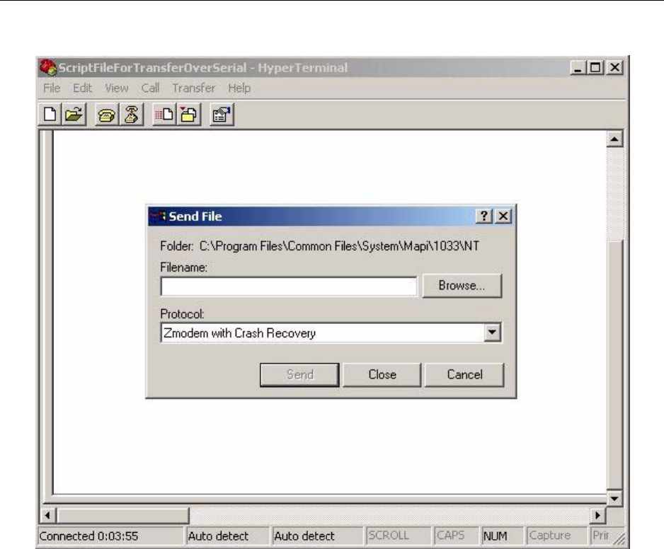
5. Open the Send File window.
Select Transfer ⇒ Send File...
Chapter 12 ● Running the commissioning script
152 Release 2.0, 910056 Rev01d
The following displays:
6. Click the Browse... button to find the script file to transfer, or, in the Filename text box, enter the path
and file name of the script file.
Transmitting a script from a laptop to the network element
IP-RN 8000 Installation & Commissioning Guide 153
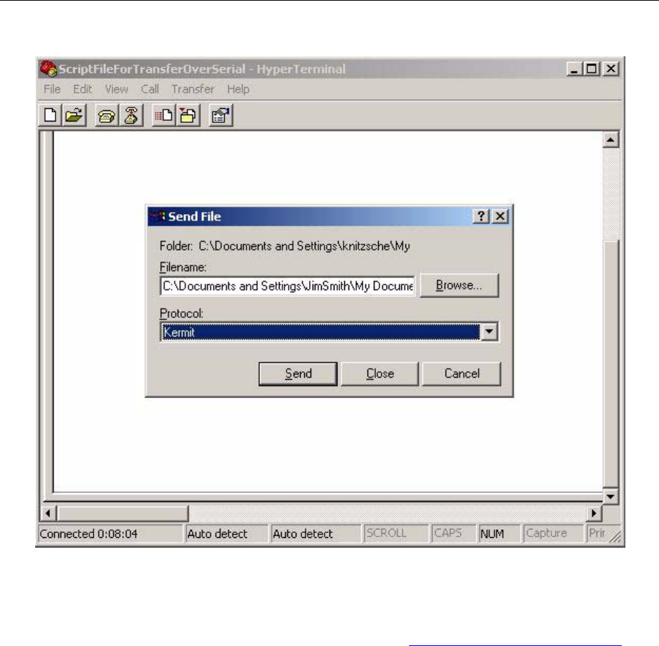
7. In the Protocol pull down selection list, select Kermit.
8. Click the Send button to send the designated script file to the node.
This procedure is complete. The script file is now transferred to the node. The next step is to return to the
node CLI shell and confirm the script file is on the node. Go to Verifying the script file is on the node on
page 154.

Chapter 12 ● Running the commissioning script
154 Release 2.0, 910056 Rev01d
Verifying the script file is on the node
This procedure explains how to verify the script file has been transferred successfully to the node and how to
leave the command shell.
1. Look at the CLI output.
If the kermit file transfer failed, an error message displays. If it has failed, attempt the transfer again by
going to Initializing the node to receive a file with kermit on page 147.
2. Check the contents of the disk0:/config directory with the ls command to see whether the script file is
present as follows:
AIRVANA-03(shell)(disk0:config)>ls
The list of files in the directory is displayed with the size of each file. Ensure the script file you
transferred is present and has a file size greater than 0.
Note that the file name is the name you entered in the CLI command kermit receive
<filename>, not the file name of the file before it was transmitted from the laptop.
If the file is not present, attempt the transfer again by going to Initializing the node to receive a file with
kermit on page 147.
3. Use the exit command to leave the command shell and return to the normal CLI prompt, as follows:
AIRVANA-03(shell)(disk0:config)>exit
The following prompt displays:
AIRVANA-03>
This procedure is complete. Go to Running the script on page 155.

Running the script
IP-RN 8000 Installation & Commissioning Guide 155
Running the script
This procedure explains how to run a configuration script.
1. Use the enable command to enter the privileged EXEC mode, as follows:
AIRVANA-03>enable
The CLI prompt changes to the Privilege EXEC prompt, as follows:
AIRVANA-03#
2. Run the commissioning script by using the CLI copy command to copy it to
system:running-config, as follows:
AIRVANA-03#copy disk0:/config/<scriptFileName> system:running-config
where:
•copy is the CLI copy command
•disk0:/config/ specifies the required path to the script
•<scriptFileName> is the name of the script file
•system:running-config is the required destination file name
Always specify system:running-config as the destination file when using the CLI copy
command to run the commissioning script.
For example: copy disk0:/config/nodea.txt system:running-config
The node runs the commissioning script you specified. When the script finishes executing, the CLI
displays the script done message, as follows:
AIRVANA-03#script done
If the script fails to execute successfully or encounters errors, the CLI displays an appropriate error
messages and the script stops running at the point where the faulty CLI command tried to execute.
3. Return to the base command prompt by typing exit followed by the <ENTER> key twice times, as
follows:
AIRVANA-03#exit
AIRVANA-03>
This procedure is complete.
WARNING
Running a configuration script changes the node’s current
configuration and can be service disrupting.

Chapter 12 ● Running the commissioning script
156 Release 2.0, 910056 Rev01d

IP-RN 8000 Installation & Commissioning Guide 157
Chapter 13
Loopback testing backhaul links
About this chapter
This chapter describes how to perform loopback tests on each backhaul cable and contains the
following sections:
•Understanding the backhaul link loopback test process on page 158
•Understanding backhaul loopback testing on page 159
•Understanding a typical T1/E1 backhaul network on page 160
•Understanding Ethernet loopbacks on page 160
•Looping back T1/E1 backhaul links on page 161
•Looping back Ethernet backhaul links on page 162
•Entering diagnostic mode and configuring test parameters on page 163
•Performing external loopback tests on backhaul links on page 164
•Troubleshooting failed backhaul links on page 166
•Removing physical loopbacks on page 168

Chapter 13 ● Loopback testing backhaul links
158 Release 2.0, 910056 Rev01d
Understanding the backhaul link loopback test process
This process explains the steps you should follow for performing loop back tests. Loopback testing each
backhaul link is recommended to ensure correct installation and operation at the physical layer.
1. Understanding the backhaul loopback process
This section explains the T1/E1 loopback testing process.
See Understanding backhaul loopback testing on page 159.
See Understanding a typical T1/E1 backhaul network on page 160.
See Understanding Ethernet loopbacks on page 160.
2. Install external loopbacks on each backhaul cable
• If the backhaul cables are T1 or E1, go to Looping back T1/E1 backhaul links on page 161
• If the backhaul link(s) are Ethernet, go to Looping back Ethernet backhaul links on page 162
3. Preparing for loopback tests
Enter CLI diagnostic mode and configure the test parameters.
See Entering diagnostic mode and configuring test parameters on page 163.
4. Running loopback tests on each backhaul
Perform the loopback test for all backhaul links.
See Performing external loopback tests on backhaul links on page 164.
5. Troubleshooting failed backhaul link(s)
Take additional steps to troubleshoot and correct any backhaul link(s) that failed the external loopback
tests.
See Troubleshooting failed backhaul links on page 166.
6. Removing physical loopbacks
The external loops at the far end of all cables must be removed.
See Removing physical loopbacks on page 168
This procedure is complete. You must complete the commissioning. Go to Understanding the
commissioning completion process on page 188.
Understanding backhaul loopback testing
IP-RN 8000 Installation & Commissioning Guide 159
Understanding backhaul loopback testing
Loopback testing each backhaul link verifies the backhaul installation was performed correctly and verifies
physical layer operation before the technician leaves the site. During manufacturing the backhaul interfaces
are loopback tested to the punch block, ensuring all internal components function properly. Loopback testing
during installation can be performed to verify the correct wiring into the punch block and the external
physical infrastructure.
The extent of the loopback test (the amount of equipment and cabling that is tested) depends on where the
physical loop back is installed. The farther away from the node the loop back is installed, the greater the
extent of the test.
Airvana recommends installing the loopback at least as far as the far end of each backhaul cable exiting the
cabinet. Installation at that point includes the backhaul cable’s wiring into the backhaul punch block and the
backhaul cable itself.
The technician must have appropriate equipment and materials for installing and performing loopbacks.
NOTE
The loop back testing described here does not include backhaul
circuits, only physical layer functionality at the cell site.
Backhaul circuits must undergo end-to-end testing and
acceptance at the time they are brought up by the service
provider.
NOTE
Ethernet loopbacks cannot be installed at the far side of a router,
switch, FRAD, or other edge device.
NOTE
Maximum cable lengths must be considered when installing
loopbacks. Loopbacks double the length of a cable (the cable
length now equals the outgoing leg plus the return leg, or twice
the physical cable length). Failure to consider this factor can
result in failed loopback tests for cables that are flawless.
Chapter 13 ● Loopback testing backhaul links
160 Release 2.0, 910056 Rev01d
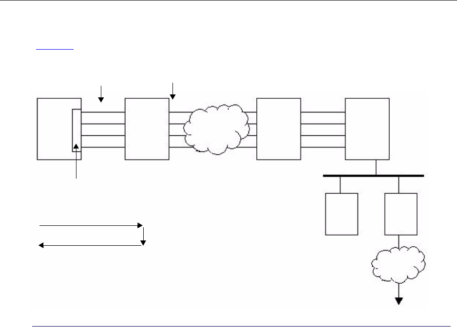
Understanding a typical T1/E1 backhaul network
Figure 22 shows a typical network in which T1s/E1s are used for backhaul link(s).
Figure 22 A typical T1/E1 backhaul network using DSXs (digital cross connects, T1/E1 multiplexors, or
similar)
Understanding Ethernet loopbacks
Like the T1/E1 loopback test, the Ethernet loopback test has two parts:
• Physically loopback the Ethernet
• Run the loopback test
The loopback can be done externally on the cable by physically connecting the receive wires (RXs) to the
transmit wires (TXs). The loopback can also be done internally on the hardware transceiver chip. Looping
back internally on the transceiver chip only tests limited hardware functionality and does not test the cable
connection or the punch down block. Looping back externally tests more. The Ethernet loopback test is not
a standard function of Ethernet but is a value-added proprietary feature.
Backhaul
1 to 4 T1s/E1s
IP-RN 8000 DSX DSX Router
RNC PDSN
Internet
TDM
backhaul
punch block
Ethernet
External test: T1/E1 loopback to
carrier demarcation point
Carrier demarcation point
Looping back T1/E1 backhaul links
IP-RN 8000 Installation & Commissioning Guide 161
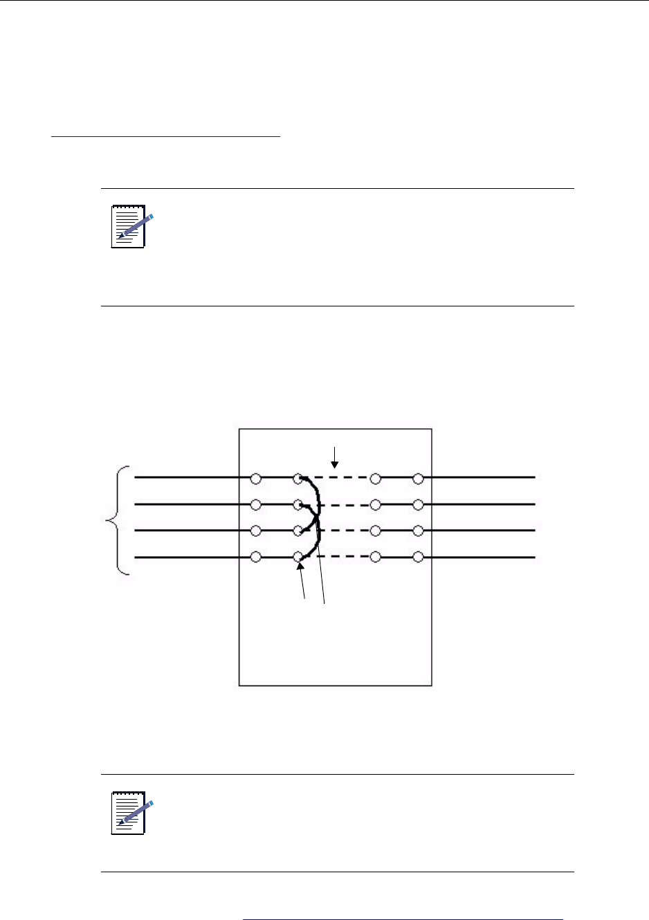
Looping back T1/E1 backhaul links
This section explains options for installing physical loopbacks when T1 or E1 backhaul link(s) are deployed
at the cell site. Because Airvana does not specify the external T1/E1 equipment used at cell sites, some
details of looping back the T1/E1 cables are site-dependent. Depending on the equipment deployed at the
site at the time of loopback testing, the location of the installed physical loopback will vary. (See also
Understanding backhaul loopback testing on page 159.) The technique used to create the loopback will also
vary depending on installed third-party equipment.
1. If the backhaul cables that exit the cabinet are connected to a DSX (or an equivalent type of equipment),
the physical loopback should be installed on the IP-RN 8000 side of the DSX (or equivalent of
equipment). Use methods and materials to install the loopback that are appropriate to the third-party
equipment.
2. If the T1/ E1 backhaul cables exiting the cabinet hang free at the far end, build a physical loopback
appropriate to the cable type and install it at the far end of the cable.
This procedure is complete. Go to Entering diagnostic mode and configuring test parameters on page 163.
NOTE
• Physical loopbacks are created by physically
connecting the positive transmit wire to the positive
receive wire and connecting the negative transmit
wire to the negative receive wire.
• Loopbacks must be installed on each and every T1/
E1 backhaul cable.
NOTE
Maximum cable lengths must be considered when installing
loopbacks. Loopbacks double the length of a cable (the outgoing
leg along the cable and the return leg). Failure to consider this
factor can result in failed loopback tests for cables that are
flawless.
DSX
TX positive
TX negative
RX positive
RX negative
IP-RN 8000 side Carrier side
Install physical loopbacks
Cross connects
A T1/E1
Chapter 13 ● Loopback testing backhaul links
162 Release 2.0, 910056 Rev01d
Looping back Ethernet backhaul links
This section explains how to install the physical loopbacks when Ethernet backhaul links are used. If the
Ethernet backhaul cable is connected to a patch panel (or another passive, pass-through device), you can
install the loopback at the far side of it and thereby include the patch panel in the test.
Because Airvana does not specify the Ethernet cable/connector types, the details of looping back the
Ethernet cables are site-dependent. Typically, Ethernet backhaul cables installed into the backhaul punch
block have an RJ-45 jack at the far-end. This section provides the pin-out for the RJ-45 jack.
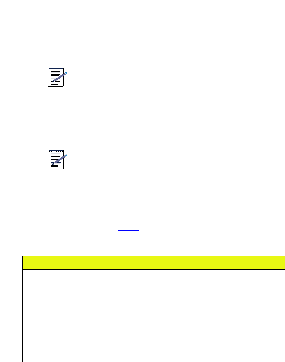
1. If the Ethernet at the point of the loopback installation has an RJ-45 connector on the far end, build a
loopback jack using the pin-out in Table 23.
2. If the Ethernet backhaul(s) have a different connector, build a loopback jack as appropriate.
3. Install the loopback connectors onto the far end of each Ethernet cable.
NOTE
You cannot loopback the Ethernet at the far side of most network
devices, including switches, routers, and FRADS.
NOTE
• Physical loopbacks are created by physically
connecting the positive transmit wire to the positive
receive wire and connecting the negative transmit
wire to the negative receive wire.
• Loopbacks must be installed on all Ethernet backhaul
cables. There is one Ethernet backhaul cable on
non-redundant systems; there are two on redundant
systems.
Table 23 RJ-45 Ethernet pin out for loopback
RJ-45 wire Description For loopback...
1 transmit, positive connect to wire 3
2 transmit, negative connect to wire 6
3 receive, positive connect to wire 1
4 unused
5 unused
6 receive, negative connect to wire 2
7 unused
8 unused

Entering diagnostic mode and configuring test parameters
IP-RN 8000 Installation & Commissioning Guide 163
This procedure is complete. Go to Entering diagnostic mode and configuring test parameters on page 163.
Entering diagnostic mode and configuring test parameters
This procedure explains how to initiate a hard reset and use the CLI to enter diagnostics mode, and how to
configure the diagnostics mode for E1 links, if E1 backhaul links are deployed (see step 4). It is assumed
that you already have a CLI link to the node through the serial port on the active BIO/SC module. (See
Establishing the CLI/serial connection on page 135.)
Requirements
No tools or materials are required.
Procedure
1. Ensure the CLI session is active by pressing the <ENTER> key on your CLI laptop. A new command
prompt appears indicating the session is active.
If the session is not active, see Establishing the CLI/serial connection on page 135.
2. Use the reset command to reboot the node as follows:
AIRVANA-03>enable
AIRVANA-03#reset
This causes the node to reboot and to run hardware diagnostics.
After hardware diagnostics run, a diagnostics countdown occurs. This countdown enables you to enter
diagnostics mode by pressing the <SPACE BAR> key three times during the countdown. The
countdown numbers are transmitted out the serial port and are visible in your CLI session.
3. During the countdown, press any the <SPACE BAR> key three times .
This causes the RN to enter diagnostics node. Loopback test commands are only available in
diagnostics mode. The diagnostic mode command prompt is”
BIOSC_3>
Where “3” is the slot number.
4. If the backhaul links are E1, enter the following three commands to configure the E1 diagnostic mode:
BIOSC_3>writeee 7FF 02
BIOSC_3>writeee 100 0
BIOSC_3>reset
Resetting the node causes another reboot. You must enter the diagnostics mode by pressing the
<SPACE BAR> key three times during that countdown as you did in step 3 in order to stay in
diagnostics mode and to continue with loopback testing.
This procedure is complete. Go to Performing external loopback tests on backhaul links on page 164.
Chapter 13 ● Loopback testing backhaul links
164 Release 2.0, 910056 Rev01d
Performing external loopback tests on backhaul links
This procedure explains how to perform loopback tests on backhaul links. It is assumed an external
loopback has already been installed on each backhaul. (See Looping back T1/E1 backhaul links on page 161
and Looping back Ethernet backhaul links on page 162). A CLI session must be active. (See Establishing the
CLI/serial connection on page 135.) The node must be in diagnostic mode. (See Entering diagnostic mode
and configuring test parameters on page 163.) If the backhaul is T1 or E1, diagnostic parameters must have
been set. (See Entering diagnostic mode and configuring test parameters on page 163.)
1. Enter the CLI command to start the loopback test.
The command is: commsend <number of tests> <ports>
Where:
•<number of tests> specifies the number times each port is to be tested. The valid range is
between (0 – 100000).
•<ports> specifies the names of the ports to be tested. See Table 24.
For example, the following command would start the loopback test for a system with two E1 backhaul
links: commsend 10 T1 T2
Table 24 Specifying the backhaul links to be tested
<ports>Indicates the following ports to be tested
T1 The first T1 or E1 backhaul
T2 The second T1 or E1 backhaul
T3 The third T1 or E1 backhaul
T4 The fourth T1 or E1 backhaul
FENET1 The primary Ethernet backhaul
NOTE
If your node uses two Ethernet backhaul links (a primary and a
redundant), you need to check them separately. First, establish a
CLI connection with the primary BIO/SC and run the loopback
test, then establish a CLI connection with the redundant BIO/SC
and run the loopback test. You can simply unplug the laptop CLI
cable from the primary BIO/SC craft port and plug it into the
redundant BIO/SC craft port. The CLI command to run the test is
the same: commsend <number of tests> fenet1.

Performing external loopback tests on backhaul links
IP-RN 8000 Installation & Commissioning Guide 165
2. Evaluate the results.
After the test is complete, the following table of data displays for each backhaul tested.
Number of Transmitted Frames : x
Number of Received Frames : x
Number of Error Frames : x
Frames without valid Test ID : x
Frames with invalid Data : x
Frame Error Rate : x
Error Counters
Rx Frame Length Violations ... x
Rx Non-octet alignment ... x
Rx Abort Frames ... x
Rx CRC Errors ... x
If the Number of Received Frames does not equal the Number of Transmitted
Frames, or if there are any errors counted, you need to troubleshoot the backhaul. Go to
Troubleshooting failed backhaul links on page 166.
This procedure is complete. Go to Removing physical loopbacks on page 168.
Chapter 13 ● Loopback testing backhaul links
166 Release 2.0, 910056 Rev01d
Troubleshooting failed backhaul links
This procedure explains how to run the internal loopback test on backhaul links that failed the external
loopback test. This section also outlines what to do based on the test results: If the internal loop back passes,
troubleshoot the cables and loopback devices. If the internal loopback fails, the node may be faulty and you
should call Airvana.
This procedure assumes the node is in diagnostic mode, a CLI session is active, and the preceding loopback
procedures have been completed.
1. If the backhaul links are T1 or E1, enter the following CLI command to specify the backhaul links you
want to set to internal loopback mode:
BIOSC>mmb <port memory locations> 04
Where:
•<port memory locations> are the backhaul links to place into internal loopback mode. See
Table 25.
For example, the following command sets the second T1 or E1 backhaul to internal loopback mode:
BIOSC>mmb f500010a 04
2. If the backhaul links are Ethernet, enter the following CLI command:
BIOSC>poke874 fenet1 13 803c
3. Run the internal backhaul test on the interface(s) you have set to internal loopback mode with the
following CLI command:
BIOSC>commsend <number of tests> <ports>
Where:
•<number of tests> specifies the number times each port is to be tested. The valid range is
between (0 – 100000).
•<ports> specifies the names of the ports to be tested. See Table 26.
Table 25 Specifying the backhaul links to be set to internal loopback mode
<port memory
location>Indicates the following ports to be set to internal loopback mode
f500000a The first T1 or E1 backhaul
f500010a The second T1 or E1 backhaul
f500020a The third T1 or E1 backhaul
f500030a The fourth T1 or E1 backhaul

Troubleshooting failed backhaul links
IP-RN 8000 Installation & Commissioning Guide 167
For example, the following command would start the loopback test for a system with two E1 backhaul
links:
BIOSC>commsend 10 T1 T2
4. Evaluate the results.
After the test is complete, the table of data displays for each backhaul tested.
Number of Transmitted Frames : x
Number of Received Frames : x
Number of Error Frames : x
Frames without valid Test ID : x
Frames with invalid Data : x
Frame Error Rate : x
Error Counters
Rx Frame Length Violations ... x
Rx Non-octet alignment ... x
Rx Abort Frames ... x
Rx CRC Errors ... x
If the Number of Received Frames does not equal the Number of Transmitted
Frames, or if there are any errors counted, the node has a fault and you need to contact Airvana. This
is the end of this procedure.
If the Number of Received Frames does equal the Number of Transmitted Frames
and there are no errors, you must troubleshoot the following:
• the backhaul cable
• the physical loopback installed earlier in the loopback testing process
• the backhaul wiring into the punch block
• any external equipment the backhaul cable is attached to, for example a digital cross connect
5. Exit diagnostics mode
Enter the following command to reset the node:
BIOSC>reset
Allow the node to reboot to completion, skipping the diagnostic mode required for loopback testing.
This procedure is complete. Go to Removing physical loopbacks on page 168.
Table 26 Specifying the backhaul links to be tested
<ports>Indicates the following ports to be tested
T1 The first T1 or E1 backhaul
T2 The second T1 or E1 backhaul
T3 The third T1 or E1 backhaul
T4 The fourth T1 or E1 backhaul
FENET1 The primary Ethernet backhaul

Chapter 13 ● Loopback testing backhaul links
168 Release 2.0, 910056 Rev01d
Removing physical loopbacks
This procedure explains the steps to restore the system to normal operational mode after loopback testing is
complete.
1. Remove all external, physical loopbacks installed earlier.
This procedure is complete. The loop back testing process is also complete. Go to Understanding the
commissioning completion process on page 188.
CAUTION
Failure to remove any loopbacks installed earlier results in failed
backhaul links.

IP-RN 8000 Installation & Commissioning Guide 169
Chapter 14
Calibrating transmit power
About this chapter
This chapter explains how to measure the transmit power budget and calibrate transmit power for
each sector. This chapter contains the following sections:
•Understanding the transmit power calibration process on page 170
•Understanding calibration purpose on page 171
•Understanding requirements on page 171
•Understanding the need for simultaneous CLI sessions on page 171
•Enabling the base station and checking the IP-RNC 8500 on page 172
•Verifying GPS status on page 172
•Disabling all sectors on page 174
•Attaching the sector’s test equipment on page 176
•Enabling and blossoming the sector to be calibrated on page 178
•Starting FTAP for the sector on page 179
•Measuring power loss for the sector on page 180
•Setting the sector’s transmit power on page 181
•Verifying the sector’s power level on page 182
•Completing the sector’s transmit power calibration process on page 183
•Blossoming and enabling all sectors on page 185

Chapter 14 ● Calibrating transmit power
170 Release 2.0, 910056 Rev01d
Understanding the transmit power calibration process
This process explains the procedures to measure antenna jumper attenuation and to calibrate transmit power
for each sector accordingly.
1. Understanding calibration purpose and requirements
See Understanding calibration purpose on page 171.
See Understanding requirements on page 171.
2. Opening two CLI/telnet sessions
Simultaneous CLI sessions are needed to the local IP-RN 8000 and the remote IP-RNC 8500. This
requires that the laptop is connected to the BIO/SC craft Ethernet and that IP is configured
appropriately.
See Understanding the need for simultaneous CLI sessions on page 171.
3. Enabling the BTS and checking the connection with the IP-RNC 8500
Enable the BTS function of the IP-RN 8000 and verify the connection with the IP-RNC 8500.
See Enabling the base station and checking the IP-RNC 8500 on page 172.
4. Verifying GPS status
Verify that GPS is locked and time is acquired.
See Verifying GPS status on page 172.
5. Disabling all sectors
All sectors must be disabled (transmission must be stopped) before continuing with the calibration.
See Disabling all sectors on page 174.
6. Calibrating each sector’s power transmission offset
Perform the following procedures in sequence for each sector deployed:
a. Attach the test equipment to the sector’s transmit jumper antenna cable
See Attaching the sector’s test equipment on page 176.
b. Enable and blossom the sector
See Enabling and blossoming the sector to be calibrated on page 178
c. Start the FTAP test for the sector
See Starting FTAP for the sector on page 179.
d. Measure the power loss at the end of the sector’s transmit antenna jumper cable at three levels and
find the average loss.
See Measuring power loss for the sector on page 180.
e. Set the sector’s transmit power.
See Setting the sector’s transmit power on page 181.
f. Verify the sector’s transmit power level
See Verifying the sector’s power level on page 182.
g. Shut the sector down, remove test equipment, and re-connect the antenna
See Completing the sector’s transmit power calibration process on page 183
This procedure is complete. You must run the commissioning script to configure the node for normal
operations. Go to Understanding the backhaul link loopback test process on page 158.

Understanding calibration purpose
IP-RN 8000 Installation & Commissioning Guide 171
Understanding calibration purpose
The purpose of the procedures in this chapter is to measure the power loss over the antenna jumper so that
you can adjust the transmission level for the sector appropriately to compensate.
Understanding requirements
The following are required to measure and calibrate the transmit power for each sector:
• The IP-RN 8000 must have been completely configured for normal operations with the commissioning
script.
• Backhaul links must be operative at the physical level and at the IP level providing connectivity to the
IP-RNC 8500 to which this IP-RN 8000 is homed.
• The IP-RNC 8500 to which this IP-RN 8000 is homed must be operating.
• You must know the management IP address of the IP-RNC 8500 to which the IP-RN 8000 is homed in
order to telnet to it.
Understanding the need for simultaneous CLI sessions
Calibrating transmit power requires two simultaneous CLI sessions, one to the local IP-RN 8000 and one to
the remote IP-RNC 8500. Simultaneous CLI sessions require a connection from the laptop to the BIO/SC
craft Ethernet port and that the appropriate IP configuration is completed. Once this connection is active,
you can open two CLI/telnet sessions, one to the local IP-RN 8000 and one to the remote IP-RNC 8500.
(Alternatively, you can use the CLI/serial connection to control the local IP-RN 8000 and use CLI/telnet to
control the remote IP-RNC 8500.)
Before proceeding, open these two CLI sessions. Opening the IP-RNC 8500 requires that you know and use
the IP-RNC 8500’s management IP address.
See Understanding the CLI connection process on page 132.

Chapter 14 ● Calibrating transmit power
172 Release 2.0, 910056 Rev01d
Enabling the base station and checking the IP-RNC 8500
This procedure explains how to enable the BTS function in the IP-RN 8000 and to verify the IP-RN 8000
has connectivity with the IP-RNC 8500 to which it is homed.
Requirements
CLI session with the IP-RN 8000
Procedure
1. Using the CLI session to the IP-RN 8000, enable the BTS function as follows:
AIRVANA-03>enable
AIRVANA-03#no shutdown
AIRVANA-03#exit
AIRVANA-03>
This configures the node to establish a connection with the IP-RNC 8500 to which it is homed.
2. Verify the node is communicating with the IP-RNC 8500, as follows:
AIRVANA-03>show abis peer
After several seconds, the following displays:
PeerAddressPortStateRxMsgsRxhellos
172.16.1.32602UP22648
If an IP address followed by a few digits and then “UP” is not displayed, the node does not have a
connection to the IP-RNC 8500. This connection is required for the test to proceed.
This procedure is complete. Go to Verifying GPS status on page 172.
Verifying GPS status
This procedure explains how to verify that the IP-RN 8000’s GPS system is operational and locked onto a
satellite.
Requirements
An IP-RN 8000 CLI session.

Verifying GPS status
IP-RN 8000 Installation & Commissioning Guide 173
Procedure
1. Verify GPS is locked to a satellite with the following:
AIRVANA-03>show gps-health
The following displays:
GPS module is present
GPS Lock Status: Locked
Even Second: Valid
If the display shows any other values, GPS is not functioning properly. Troubleshoot the following:
• The TFU module containing the GPS module. Ensure that it is properly inserted in the chassis and
that its LEDs indicate normal operations.
• Verify that the GPS antenna jumper cables exiting the cabinet through the Rox System cabinet seal
are properly connected to GPS antennas and that those antennas are functioning properly.
2. Enter the following command to display the current UTC (Universal Time Coordinated) time as
reported by the GPS module:
AIRVANA-03>show gps time
The GMT time displays:
Current UTC Time read from the GPS: 19:32:18 07/01/02
Even-second is valid.
Verify the time displayed is correct.
If the correct time does not display, troubleshoot the GPS antennas and receivers.
This procedure is complete. Disabling all sectors on page 174.
NOTE
It can take 10 minutes after the GPS antenna is connected and the
TFU module is powered on for the GPS to acquire and display
the correct time.
Chapter 14 ● Calibrating transmit power
174 Release 2.0, 910056 Rev01d
Disabling all sectors
This procedure explains how to ensure all sectors are disabled for transmission.
Requirements
• A CLI session to the IP-RN 8000
Procedure
1. Check the sector status with the following CLI command:
AIRVANA-03>show sector-element
Name Carrier Sector CAI Channel Power Admin Oper
--------------------------------------------------------------------
element1/4/1 carrier1 sector1 IS-856 850 35 dBm DOWN DOWN
element1/4/2 carrier1 sector2 IS-856 850 35 dBm DOWN DOWN
element1/4/3 carrier1 sector3 IS-856 850 35 dBm DOWN DOWN
The display shows all sectors. Before continuing, all sectors must have an Admin of DOWN and an
Oper of DOWN.
WARNING
Failure to disable sectors before proceeding can release EMI
radiation. This can cause injury and can results in interference
with other EMI devices.
NOTE
Terminology note: Sectors can be “enabled” (turned on) and
disabled (turned off). If a sector is enabled, the transmit power
can be “blossomed” (turned on) or “wilted” (turned off).

Disabling all sectors
IP-RN 8000 Installation & Commissioning Guide 175
2. If any sector does not have an Admin of DOWN and an Oper of DOWN, you must shut it down using
the following commands (this example shuts down all three sectors):
AIRVANA-03>enable
AIRVANA-03#configure
AIRVANA-03(config)#sector-element element1/4/1
AIRVANA-03(config-element)#shutdown
AIRVANA-03(config-element)#exit
AIRVANA-03(config)#sector-element element1/4/2
AIRVANA-03(config-element)#shutdown
AIRVANA-03(config-element)#exit
AIRVANA-03(config)#sector-element element1/4/3
AIRVANA-03(config-element)#shutdown
AIRVANA-03(config-element)#exit
AIRVANA-03(config)#exit
AIRVANA-03#exit
This procedure is complete. Go to Attaching the sector’s test equipment on page 176.
Chapter 14 ● Calibrating transmit power
176 Release 2.0, 910056 Rev01d
Attaching the sector’s test equipment
This procedure explains how to attach test equipment to the sector’s transmit antenna jumper cable exiting
the cabinet.
Required tools
The following tools are used if the antenna jumper cables exiting the cabinet used standard N-type
connectors to attach to external equipment. If you assembled your own jumper cables using different
connectors, you need appropriate tools.
• 13/16 inch open ended wrench
• Torque wrench with 13/16 inch open ended bit
• 30 dB attenuator pad with connector appropriate for antenna jumper cable rated for a maximum of 50
watts
• Power splitter to split the transmit signal for use by the power meter and the AT, with appropriate cables
and connector adapters
• Power meter with connector appropriate for coupler
• 1xEV-DO access terminal (AT)
Warnings
WARNING
You must have disabled the sector before continuing. Failure to
disable the sectors can result in EMI radiation that could cause
injury and could cause interference with other devices.
WARNING
Antenna cables emit radio frequency energy. Exposure to radio
frequency energy can cause burns or other health problems. Take
all appropriate precautions to avoid risk and danger.
WARNING
Do not touch or disconnect antennas when there is any chance of
a lightning strike. Injury or death can occur if lightning strikes an
antenna during installation.
Attaching the sector’s test equipment
IP-RN 8000 Installation & Commissioning Guide 177
Procedure
1. Identify the sector you are calibrating.
For information about sectors, see Understanding radio sectors on page 14.
2. Identify the transmit antenna jumper cable for the sector exiting the Rox System cabinet seal.
For information about identifying the transmit jumper cable for the sector, see RF and GPS cable
locations on page 101.
3. Use the 13/16 inch open ended wrench to disconnect the transmit antenna jumper cable for the sector
from external equipment.
4. Attach a 30 dB attenuator pad to the end of the antenna jumper cable.
5. Connect the power splitter to the attenuator, using appropriate adapters.
6. Connect the power meter to one branch of the power splitter using appropriate adapters.
7. Connect the AT to the other branch of the power splitter using appropriate adapters.
This procedure is complete. Go to Enabling and blossoming the sector to be calibrated on page 178.
WARNING
Failure to attach attenuator pad may result in damage to the power
meter and the access terminal.
NOTE
You must account for the attenuator when making power budget
calibrations later.
NOTE
You must account for the power splitter when making power
budget calibrations later.

Chapter 14 ● Calibrating transmit power
178 Release 2.0, 910056 Rev01d
Enabling and blossoming the sector to be calibrated
This procedure explains how to enable the sector being calibrated and turn on (blossom) transmission for the
sector. This is needed for the AT to establish an active 1xEV-DO session with the IP-RNC 8500.
Requirements
• CLI session to the IP-RN 8000
• CLI session to the IP-RNC 8500
• A turned on 1xEV-DO AT
• All sectors are disabled
Procedure
1. Use the CLI session to the IP-RN 8000 to enable and blossom the sector being calibrated, as follows:
AIRVANA-03>enable
AIRVANA-03#configure
AIRVANA-03(config)#sector-element <sector-element>
Where: <sector-element> is element1/4/1 for sector1/alpha, element1/4/2 for sector2/
beta, element1/4/3 for sector1/gamma
AIRVANA-03(config-element)#tx-power 25
AIRVANA-03(config-element)#no shutdown
AIRVANA-03(config-element)#exit
AIRVANA-03(config)#exit
AIRVANA-03#exit
2. Verify the sector is up as follows:
AIRVANA-03>show sector-element
Name Carrier Sector CAI Channel Power Admin Oper
--------------------------------------------------------------------
element1/4/1 carrier1 sector1 IS-856 850 25 dBm UP UP
element1/4/2 carrier1 sector2 IS-856 850 35 dBm DOWN DOWN
element1/4/3 carrier1 sector3 IS-856 850 35 dBm DOWN DOWN
The sector you blossomed should have an Admin of UP and an Oper of UP.
This procedure is complete. Go to Starting FTAP for the sector on page 179.

Starting FTAP for the sector
IP-RN 8000 Installation & Commissioning Guide 179
Starting FTAP for the sector
This procedure explains how to get the UATI identifier for the AT that is required for the FTAP test and how
to start the FTAP test. Starting FTAP cause the IP-RNC 8500 to transmit a steady stream of data to the
specified AT using the current sector (only one sector at a time is enabled). This causes the IP-RN 8000 to
transmit to the AT at a steady rate, enabling power measurement and calibration.
Requirements
• A 1xEV-DO access terminal (AT)
• A CLI session to the IP-RN 8000
• A CLI session to the IP-RNC 8500
Procedure
1. Ensure the AT is turned on and has establisedh a 1xEV-DO connection.
How to do this depends on the type of AT. It may just require turning the AT on, or additional steps may
be required.
2. Use the CLI session to the IP-RNC 8500 to find the AT’s UATI as follows:
AIRVANA-07>enable
AIRVANA-07#show 1xevdo session all 1001 40
The following displays (the complete table is not displayed here):
UATI List
Inst UATI24 RATI ...
(Dec) (Hex) ...
---------------------------------------------------------------------
1 10 000003F2 ...
The UATI in this case is 000003F2.
If no UATI is displayed, there may be a problem with the AT or with the network. This test requires a
completely configured and operational IP-RAN network and an operational 1xEV-DO AT.
3. Still using the CLI session to the IP-RNC 8500, enter TAP configuration mode, as follows
AIRVANA-07#tap
4. Configure the TAP session with the UATI of the AT discovered above, as follows:
AIRVANA-07(tap)#user 0x3f2
Where: 0x indicates hexadecimal and 3f2 is the UATI found above (leading zeros are not required)
5. Start the FTAP test as follows:
AIRVANA-07(tap-0x3f2)#at-tx-mode ftap-loopback
AIRVANA-07(tap-0x3f2)#start ftap 3600
Where 3600 is the number of seconds the FTAP test runs without being intentionally stopped.
Using 3600, the FTAP test will stop in one hour. If you have not completed the calibration for this sector
by then, you must restart the FTAP test.
This procedure is complete. Go to Measuring power loss for the sector on page 180.

Chapter 14 ● Calibrating transmit power
180 Release 2.0, 910056 Rev01d
Measuring power loss for the sector
This procedure explains how to measure the loss of transmit power over the sector’s transmit jumper cable
and test equipment at three different transmit power levels.
Requirements
A CLI session to the IP-RN 8000
Procedure
1. Using the CLI session to the IP-RN 8000, set the sector’s transmit power level to 25 dBm as follows:
AIRVANA-03>enable
AIRVANA-03#configure
AIRVANA-03(config)#sector-element element1/4/1
AIRVANA-03(config-element)#tx-power 25
AIRVANA-03(config-element)#no shutdown
These commands configure the first sector (identified by sector-element element1/4/1).
To configure sector 2, use: sector-element element1/4/2.
To configure sector 3, use: sector-element element1/4/3.
2. As a result of these commands, the sector transmission blossoms. Wait until the power meter shows a
stable power level. Find the differences between this detected power level and the configured transmit
power level (25 dB) and write it down. The detected power level should be somewhat less than the
transmit power level due to power lost over the antenna jumper cable and test equipment.
3. Change the transmit power level for the sector to 35 dBm using the following:
AIRVANA-03(config-element)#tx-power 35
4. The sector transmission blossoms. Wait until the power meter shows a stable power level. Find the
differences between this detected power level and the configured transmit power level (35 dB) and write
it down.
5. Change the transmit power level for the sector to 45 dBm using the following:
AIRVANA-03(config-element)#tx-power 45
6. The sector transmission blossoms. Wait until the power meter shows a stable power level. Find the
differences between this detected power level and the configured transmit power level (35 dB) and write
it down.
7. Find the average of the three numbers you calculated. Each of those calculations was the power loss at a
given transmit level. The average of those is the average power loss (without compensation for test
equipment) and is used to calibrate the power level of the transmission on this sector.
This procedure is complete. Go to Setting the sector’s transmit power on page 181.

Setting the sector’s transmit power
IP-RN 8000 Installation & Commissioning Guide 181
Setting the sector’s transmit power
This procedure explains how to calibrate the sector’s power transmission level using the results of the power
loss measurements taken in the previous procedure.
Requirements
• A CLI session to the IP-RN 8000
• The average dB loss for the sector calculated in the previous procedure
Procedure
1. Calculate the power loss parameter for the CLI command using the average power loss from the
previous procedure as follows:
a. Subtract the power loss of the power splitter and attenuator.
b. Round the result off to the nearest 1/8th (to the nearest 0.125)
For example, if the average dB power loss was 33.55 dB and the power splitter and attenuator have a
combined loss of 32 dB:
a. 33.55 — 32 = 1.55
b. 1.55 rounded to the nearest 1/8th is 1.625
So, the result is 1.625. This result is used in the next step.
2. Turn off the sector as follows:
AIRVANA-03>enable
AIRVANA-03#configure
AIRVANA-03(config)#sector-element element1/4/1
Use element1/4/2 for sector 2/beta and element1/4/3 for sector 3/gamma
AIRVANA-03(config-element)#shutdown
3. Set the transmit power level for the sector as follows:
AIRVANA-03(config-element)#pa-offset +1.625
Where +1.625 is the result calculated in step 1
4. Turn on the sector as follows:
AIRVANA-03(config-element)#no shutdown
AIRVANA-03(config-element)#exit
AIRVANA-03(config)#exit
AIRVANA-03#exit
This procedure is complete. Go to Verifying the sector’s power level on page 182.

Chapter 14 ● Calibrating transmit power
182 Release 2.0, 910056 Rev01d
Verifying the sector’s power level
This procedure explains how to verify the sector’s calibration.
Requirements
A CLI session to the IP-RN 8000
Procedure
1. At the CLI session to the IP-RN 8000, use the following commands to set the power level to 25 dBm:
AIRVANA-03>enable
AIRVANA-03#configure
AIRVANA-03(config)#sector-element element1/4/1
AIRVANA-03(config-element)#tx-power 25
AIRVANA-03(config-element)#no shutdown
These commands configure the first sector (identified by element1/4/1).
• To configure sector 2, use: sector-element element1/4/2.
• To configure sector 3, use: sector-element element1/4/3.
2. As a result of these commands, the sector transmission blossoms. Wait until the power meter shows a
stable power level and write it down.
3. Change the transmit power level for the sector to 35 dBm using the following:
AIRVANA-03(config-element)#tx-power 35
4. The sector transmission blossoms. Wait until the power meter shows a stable power level and write it
down.
5. Change the transmit power level for the sector to 45 dBm using the following:
AIRVANA-03(config-element)#tx-power 45
6. The sector transmission blossoms. Wait until the power meter shows a stable power level and write it
down.
7. Analyze the results to see if calibration is successful.
All three measurements should be within 1 dBm of the transmit power set with the tx-power
command after compensation for the power loss in the power coupler and attenuator pad.
• If all three results after compensating for the power splitter and attenuator pad are within 1 dB of
the power level set, the sector’s transmission power has been calibrated successfully.
• If any of the three results after compensating for the power splitter and attenuator pad are not within
0.5 dBm of the power level set, the sector’s transmission power has not been calibrated
successfully.
8. At this point you can optionally connect a radio frequency spectrum analyzer to the Tx sample port on
the PA module for the sector and analyze the wave form for correctness. For information about the Tx
sample port, see Understanding the Power Amplifier module on page 18.
This procedure is complete.
Completing the sector’s transmit power calibration process
IP-RN 8000 Installation & Commissioning Guide 183
• If the sector’s calibration is successful, go to Completing the sector’s transmit power calibration process
on page 183.
• If the sector’s calibration is not successful, go to Measuring power loss for the sector on page 180.
Completing the sector’s transmit power calibration process
This procedure explains how to stop FTAP for the sector and remove test equipment in preparation for
calibrating the next sector or completing the entire calibration process, as appropriate.
Requirements
If you assembled your own jumper cables using different connectors, you need appropriate, site-specific
tools.
• 13/16 inch open ended wrench
• Torque wrench with 13/16 inch open ended bit
• 30 dB attenuator pad with connector appropriate for antenna jumper cable
• Power meter with connector appropriate for antenna jumper cable
• An operational CLI/serial session to the active BIO/SC module
• See Establishing the CLI/serial connection on page 153.
Warnings
WARNING
Antenna cables emit radio frequency energy. Exposure to radio
frequency energy can cause burns or other health problems. Take
all appropriate precautions to avoid risk and danger.
Do not touch or disconnect antennas when there is any chance of
a lightning strike. Injury or death can occur if lightning strikes an
antenna during installation.
Chapter 14 ● Calibrating transmit power
184 Release 2.0, 910056 Rev01d
Procedure
1. Shut down the sector as follows (this example shuts down sector1):
AIRVANA-03>enable
AIRVANA-03#configure
AIRVANA-03(config)#sector-element element1/4/1
AIRVANA-03(config-element)#shutdown
• To shut down sector 2, use: sector-element element1/4/2.
• To shut down sector 3, use: sector-element element1/4/3.
AIRVANA-03(config-element)#exit
AIRVANA-03(config)#exit
AIRVANA-03#exit
AIRVANA-03>
2. Use the CLI session with the IP-RNC 8500 to stop the FTAP session as follows:
AIRVANA-07>(tap-0x3f2)#exit
AIRVANA-07>(tap)#exit
AIRVANA-07#exit
AIRVANA-07>
3. Disconnect the power meter, attenuator pad, and power splitter from the end of the transmit jumper
cable for the sector.
4. Connect the antenna jumper cable that was just attached to the test equipment to the proper external
antenna cable/surge protection equipment.
The connections are typically N-type and require a 13/16 inch open ended wrench. If you assembled
your own jumper cables, the connector type may be different
Tighten connections snugly. Do not overtighten.
This procedure is complete.
• If you have completed calibration of all sectors, go to Blossoming and enabling all sectors on page 185.
• If you still have sectors to calibrate, go to Starting FTAP for the sector on page 179.
CAUTION
All external antenna cables exiting the Rox System cabinet seal
must be connected to an external surge suppression system, even
if the cables are not used. Failure to connect unused cables to a
surge suppression system leaves them open to lightning strikes,
which could damage the IP-RN 8000.
Blossoming and enabling all sectors
IP-RN 8000 Installation & Commissioning Guide 185
Blossoming and enabling all sectors
This procedure explains how to restart transmission (blossom) for all sectors deployed on the node. This
procedure is only followed after all sectors have been calibrated and all test equipment is removed.
Requirements
• An operational CLI/serial session to the active BIO/SC module
• See Establishing the CLI/serial connection on page 153.
Procedure
1. If sector 1 (alpha) is deployed on the node, set the power transmission level to the figure specified by
network planners and blossom the transmission as follows:
AIRVANA-03>enable
AIRVANA-03#configure
AIRVANA-03(config)#sector-element element1/4/1
AIRVANA-03(config-element)#tx-power <specified by network planners>
AIRVANA-03(config-element)#no shutdown
AIRVANA-03(config-element)#exit
AIRVANA-03(config)#exit
AIRVANA-03#exit
AIRVANA-03>
2. If sector 2 (beta) is deployed on the node, set the power transmission level to the figure specified by
network planners and blossom the transmission as follows:
AIRVANA-03>enable
AIRVANA-03#configure
AIRVANA-03(config)#sector-element element1/4/2
AIRVANA-03(config-element)#tx-power <specified by network planners>
AIRVANA-03(config-element)#no shutdown
AIRVANA-03(config-element)#exit
AIRVANA-03(config)#exit
AIRVANA-03#exit
AIRVANA-03>
WARNING
Do not blossom and enable sectors unless all calibration is
complete, all test equipment is removed, and all antennas are
reconnected.

Chapter 14 ● Calibrating transmit power
186 Release 2.0, 910056 Rev01d
3. If sector 3 (gamma) is deployed on the node, set the power transmission level to the figure specified by
network planners and blossom the transmission as follows:
AIRVANA-03>enable
AIRVANA-03#configure
AIRVANA-03(config)#sector-element element1/4/3
AIRVANA-03(config-element)#tx-power <specified by network planners>
AIRVANA-03(config-element)#no shutdown
AIRVANA-03(config-element)#exit
AIRVANA-03(config)#exit
AIRVANA-03#exit
AIRVANA-03>
4. Verify all sectors are operational as follows.
AIRVANA-03>show sector-element
Name Carrier Sector CAI Channel Power Admin Oper
--------------------------------------------------------------------
element1/4/1 carrier1 sector1 IS-856 850 XX dBm UP UP
element1/4/2 carrier1 sector2 IS-856 850 XX dBm UP UP
element1/4/3 carrier1 sector3 IS-856 850 XX dBm UP UP
The sector you blossomed should have an Admin of UP and an Oper of UP
The Power is as you configured it for each sector.
This procedure is complete. Go to Chapter 15, Completing commissioning.

IP-RN 8000 Installation & Commissioning Guide 187
Chapter 15
Completing commissioning
About this chapter
This chapter explains how to complete the commissioning process. This chapter contains the
following sections:
•Understanding the commissioning completion process on page 188
•Checking the modules with CLI on page 188
•Disconnecting the laptop on page 189
•Preparing the cabinet for your departure on page 189
•Preparing the site for your departure on page 190

Chapter 15 ● Completing commissioning
188 Release 2.0, 910056 Rev01d
Understanding the commissioning completion process
This process explains the steps you must take to complete the commissioning process.
1. Checking the status of all modules with CLI
See Checking the modules with CLI on page 188
2. Disconnecting the Laptop
See Disconnecting the laptop on page 189
3. Ensuring the cabinet is prepared for your departure
See Preparing the cabinet for your departure on page 189
4. Ensuring the site is prepared for your departure
See Preparing the site for your departure on page 190
This is the end of the commissioning phase. Now that installation and commissioning is complete, you are
done with this book. The next phase is network integration, in which network-wide connectivity tests are
performed and other steps are taken to ensure network operation.
Checking the modules with CLI
This procedure explains how to check the node to ensure all modules are operational. It is assumed you have
an open CLI session to the active BIO/SC module.
1. Enter the following command to display a report showing the status of all modules:
AIRVANA-03>show module
The following displays:
Name Contains Status Up Time
slot1/1 radio1/1/1 Active 000d:00h:02m:14s
slot1/2 tfu1/2/1 Active 000d:00h:02m:14s
slot1/3 sc1/3/1 Active 000d:00h:02m:18s
slot1/4 modem1/4/1 Active 000d:00h:02m:14s
slot1/5 radio1/5/1 Active 000d:00h:02m:14s
slot1/6 tfu1/6/1 Active 000d:00h:02m:14s
slot1/7 sc1/3/1 Ative 000d:00h:02m:14s
slot1/8 modem1/8/1 Active 000d:00h:02m:14s
slot1/9 radio1/9/1 Active 000d:00h:02m:14s
Every module in the network element is listed with a status of Active.

Disconnecting the laptop
IP-RN 8000 Installation & Commissioning Guide 189
Disconnecting the laptop
This procedure explains how to disconnect the laptop and close it’s front door shelf in preparation for
departure.
1. Unplug the serial cable from the laptop’s COM port and from the BIO/SC module craft port.
2. If the laptop is connected to the node over Ethernet, disconnect all Ethernet cables.
3. Turn the laptop off.
4. Remove the laptop from the front door laptop shelf.
For information about the laptop front door shelf, see Figure 3 on page 5.
5. Close the front door laptop shelf.
See Closing the PC shelf on page 202.
6. Leave any pertinent notes or documents in the front door document holder.
This procedure is complete.
Preparing the cabinet for your departure
This procedure explains how to prepare the cabinet for the departure of the field technician.
1. Visually examine the cabinet’s interior and exterior from all sides and inspect for:
• Loose cables that might interfere with the front door closing
• Loose modules that should be inserted properly but are not inserted all the way
• Any access panels that are not installed properly
• Loose power or backhaul cables exiting the cabinet that are not properly enclosed in conduit
• Improperly installed conduit
• Loose or dangling antenna cables
• Check the gasket on the inside edge of the front door.
This gasket should be seated properly all the way around.
• Anything out of the ordinary
2. Press in the tech-on-site switch.
See Understanding the tech-on-site switch on page 36.
TIP
You might want to leave the cable in the document holder on the
inside of the front door. for information about the document
holder, see Figure 3 on page 5.
CAUTION
Failure to ensure the all aspects of the installation were properly
performed before leaving the site can result in damage to the
equipment or service interruption.

Chapter 15 ● Completing commissioning
190 Release 2.0, 910056 Rev01d
3. Close the front door.
See Closing the door on page 199.
4. Use a padlock to lock the cabinet front door.
This procedure is complete.
Preparing the site for your departure
This procedure explains how to prepare the site for the departure of the field technician.
1. Remove all packing containers or trash and dispose of it properly.
2. Visually inspect the site and fix any problems.
3. Close and lock any:
• Equipment boxes or pedestals
• Gates or fences
This is the end of the commissioning phase. Now that installation and commissioning is complete, you are
done with this book. The next phase is network integration, in which network-wide connectivity tests are
performed and other steps are taken to ensure network operation.

IP-RN 8000 Installation & Commissioning Guide 191
Appendix A
IP-RN 8000 Specifications
About this appendix
This appendix provides specifications for the IP-RN 8000. It contains a series of tables and sections
covering these specifications:
•IP-RN 8000 physical and environmental specifications on page 192
•Power specifications on page 193
•Grounding connection specifications on page 193
•Backhaul cable and power cable access ports on page 193
•Bell Core Earthquake Standards on page 194
•Connectors, screws, nuts, washers on page 194
•Module physical specifications on page 195
•Backhaul cable specifications on page 195
•DB-9 BIO/SC serial port pin-out on page 196
•Compliance with regulatory and industry standards on page 196

Appendix A ● IP-RN 8000 Specifications
192 Release 2.0, 910056 Rev01d
Table 27 IP-RN 8000 physical and environmental specifications
Specification Description
Weight Fully populated approximately 630 lbs (286 kg)
Dimensions Height 59.5 inches (1511.3 mm)
Width 30.5 inches (774.7 mm)
Depth 39 inches (990.5 mm)
Operating temperature range With heater -40°C to 46°C
Without heater -10°C to 46°C
Startup and operation is possible at temperatures as low
as -40°C, but the IP-RN 8000 may not satisfy all
specifications below -10°C.
Rate of temperature change Not to exceed a change of more than 15°C per hour.
Non-operating (storage) ranges Temperature -40°C to 70° C
Humidity 0 to 95% noncondensing
Loading Wind 150 miles per hour. Exp. D (241 kilometers per hour)
Snow 60 pounds per square foot (may be higher depending on
installation) (27.2 kilograms per square
Seismic Bellcore Zone 4 (GRE-CORE)
Ratings UL UL 1950 (UL60950)
Construction Aluminum structure and body
Lifting eyes 1/2 inch diameter
Heat exchanger Closed loop design for use outdoors
Standard alarms High temperature Set-point 70°C
Low temperature Set-point 14°C
Intrusion On front door (pull the tech-on-site switch to override
the door alarm)
Altitude Maximum 3000 meters
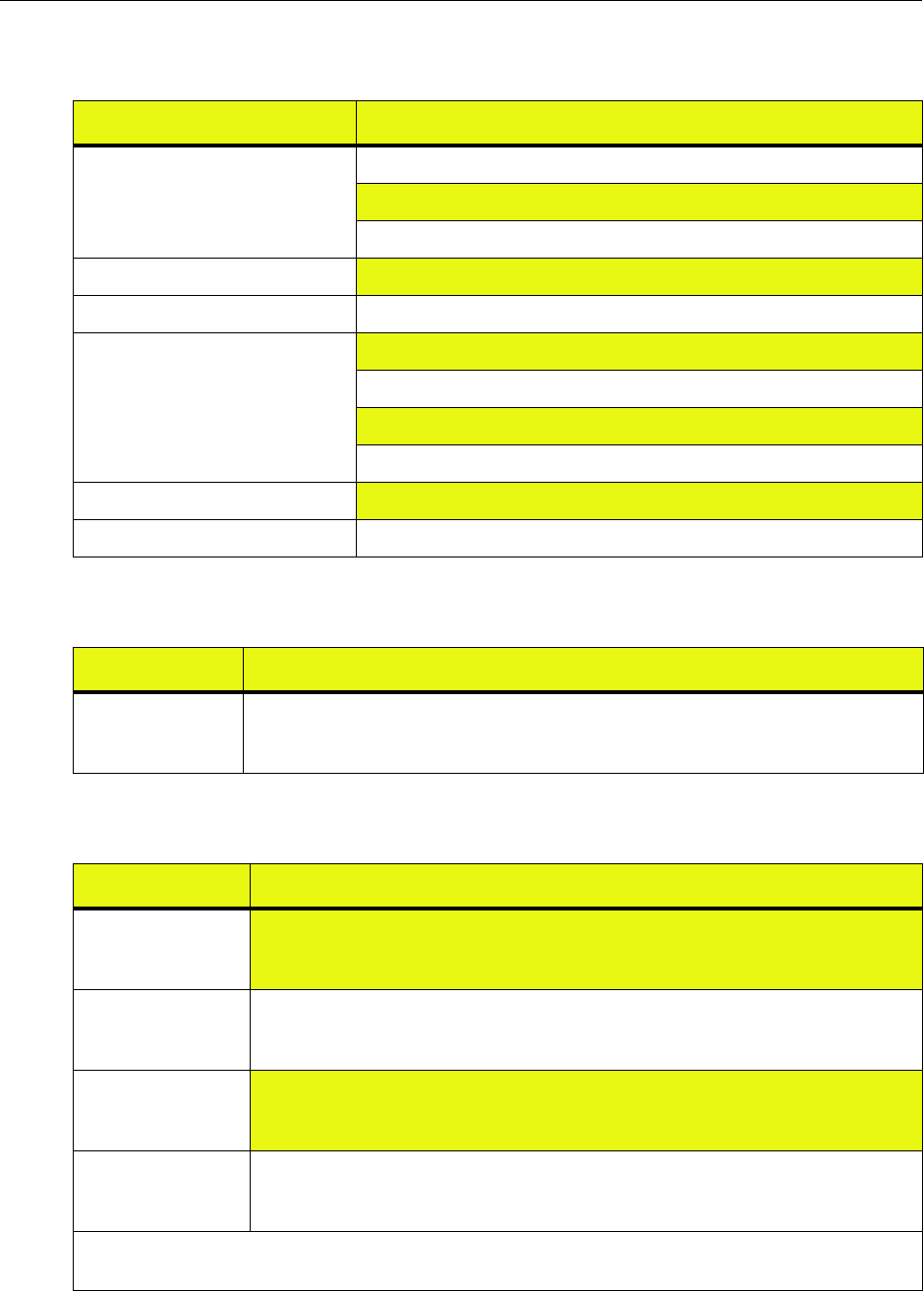
IP-RN 8000 Installation & Commissioning Guide 193
Table 28 Power specifications
Specification Description
Input Voltage Operating Range 24 V DC to 29 V DC
27 V DC nominal at the cabinet power terminal
Negative Return
Input Drop Out Time Drops to 0V for 100 uSec max
Input Current 85 A maximum without a heater
Input Voltage ripple and noise over
all load and environment conditions
< 100 mV peak to peak from 0 – 20 MHz
< 200 mV peak to peak from 0 – 100 MHz
< 19 mV RMS from 0 – 10 MHz
< 5 mV RMS from 0 – 100 KHz
Power cable 2/0 maximum, 1/0 minimum
Ground cable 1/0
Table 29 Grounding connection specifications
Specification Description
Optional side
grounding
connections
Three pairs of threaded holes designed for dual hole lugs. The thread specification is 1/4-20.
Table 30 Backhaul cable and power cable access ports
Specification Description
Backhaul cable
access port - Airvana
fixture attached
1 inch diameter access port for backhaul cables. Conduit must be attached as appropriate for
local conditions and according to local code requirements.
Backhaul cable
access port - Airvana
fixture removed
1.36 inches diameter
Power cable access
port - Airvana
fixture* attached
3 inch diameter access port for power cables and optionally for backhaul cables. Conduit
must be attached as appropriate for local conditions and according to local code
requirements.
Power cable access
port - Airvana
fixture* removed
3.54 inches diameter
* The fixture is a removable connector on the conduit opening. You can install conduit with the fixture in place or
removed as appropriate.
Appendix A ● IP-RN 8000 Specifications
194 Release 2.0, 910056 Rev01d
Table 31 Bell Core Earthquake Standards
Specification Description
Bell Core Zone 4 Installations procedures in this guide provide protection from earthquakes in the following
Bell Core seismic zones: Zone 1, Zone 2, Zone 3, and Zone 4.
Table 32 Connectors, screws, nuts, washers
RF cables Male N-type connector. Use 13/16 inch open ended wrench.
GPS cables Male N-type connector. Use 13/16 inch open ended wrench.
Access panel screws Tamper proof screw with rubber lock washer.
• Screw: button socket, 1/4-20 by 3/4 inch, stainless steel, with pin.
• Washer: lock washer, SLFSE, 1/4 inch
Tamper resistant
screw driver
5/32 inch tamper resistant hex driver
Access panel gasket
washer
RACO 1209 washer
Cabinet anchor bolts • Bolt: stainless steel, 1/2-inch bolts rated as ASTM, F-593, condition C (minimum)
• Washer: stainless steel 1/2 inch flat washer
• Lock washer: stainless steel 1/2 inch lock washer
The bolts must extend at least 1.125 inches above the concrete pad and not more than 1.5
inches about the concrete pad.
IP-RN 8000 Installation & Commissioning Guide 195
Table 33 Module physical specifications
Module Specification
BIO/SC
Base Input Output/System
Controller
Weight 4 lbs (1.8 kg)
Height 17.5 inches (444.5 mm)
Length 15.0 inches (381 mm)
Depth 1.2 inches (30.48 mm)
TFU
(Timing Frequency Unit)
Weight 5 lbs (2.3 kg)
Height 17.5 inches (444.5 mm)
Length 15.0 inches (381 mm)
Depth 2.2 inches (55.88 mm)
1xDOM
(1xEV Data Only
Modem)
Weight 5 lbs (2.3 kg)
Height 17.5 inches (444.5 mm)
Length 15.0 inches (381 mm)
Depth 1.2 inches (30.48 mm)
RM
(Radio Module)
Weight 5.5 lbs (2.5 kg)
Height 8.25 inches (209.55 mm)
Length 15.0 inches (381 mm)
Depth 3.8 inches (96.52 mm)
PA
(Power Amplifier)
Weight 22 lbs (10 kg)
Height 13.2 inches (335.88 mm)
Length 15.3 inches (388.62 mm)
Depth 3.8 inches (96.52 mm)
Table 34 Backhaul cable specifications
Backhaul type Descriptions
Ethernet Maximum length: 200 feet (60.96 meters).
Temperature range: -40°C to 70°C
Maximum diameter: 0.562 inches (1.43 centimeters)
T1/E1 ANSI/EIA/TIA 568
Temperature range: -40°C to 70°C
Maximum diameter: 0.562 inches (1.43 centimeters)
Appendix A ● IP-RN 8000 Specifications
196 Release 2.0, 910056 Rev01d
Table 35 DB-9 BIO/SC serial port pin-out
Pin Description
1 Not connected
2TXD
3RXD
4Not connected
5 Ground
6Ground
7CTS
8RTS
9 Not connected
Table 36 Compliance with regulatory and industry standards
Type Standard
Safety Certification CSA-C22.2 No. 60950
EMC FCC Part 15 Class A
FCC Part 24
T1 Interconnection FCC Part 68
Bell Core GR-487-CORE
GR-1089-CORE Level 3
GR-63-CORE Level 3
Seismic Bellcore Zone 4 (GRE-CORE)

IP-RN 8000 Installation & Commissioning Guide 197
Appendix B
Using the door
About this appendix
This appendix describes how to use the IP-RN 8000 front door. It contains these sections:
•Opening the door on page 198
•Closing the door on page 199
•Padlocking the door on page 200
•Opening the PC shelf on page 201
•Closing the PC shelf on page 202
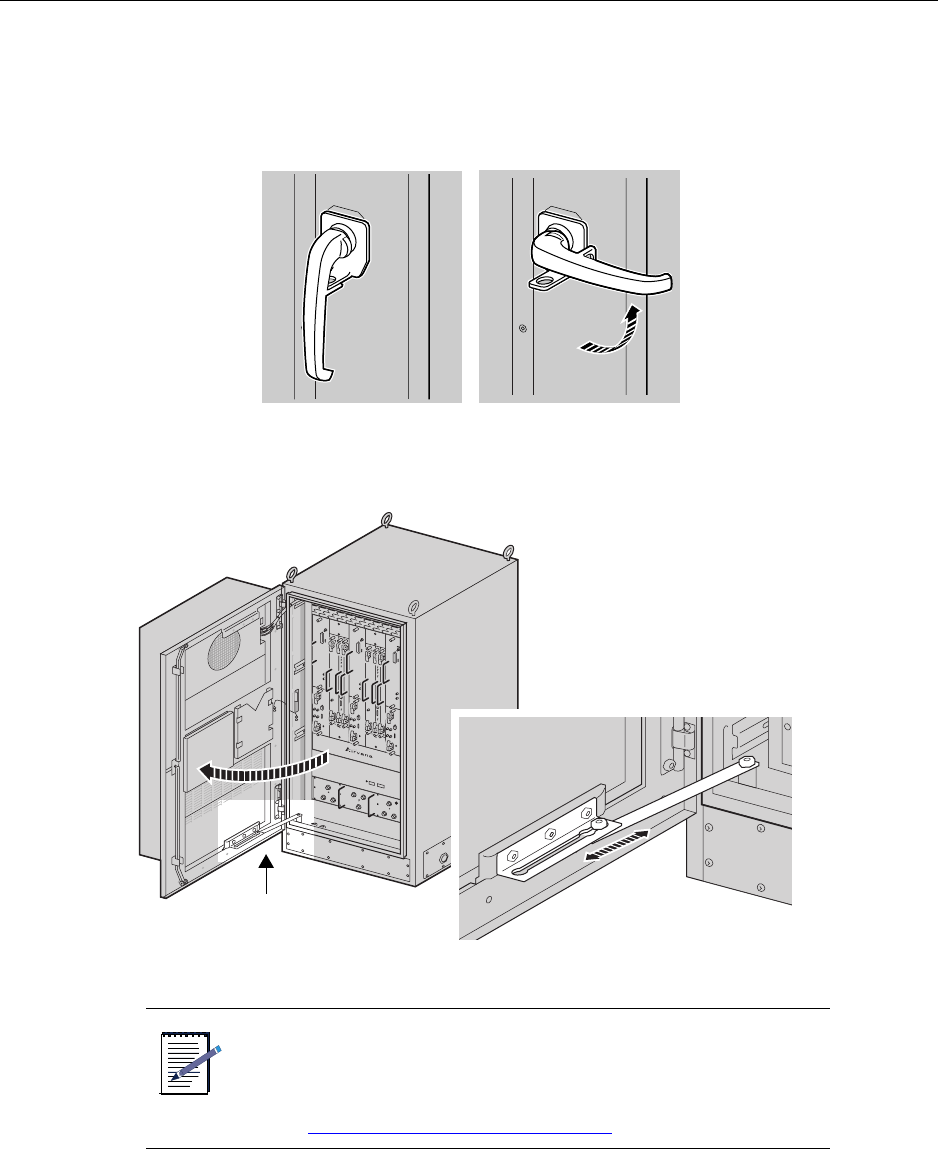
Appendix B ● Using the door
198 Release 2.0, 910056 Rev01d
Opening the door
To open the front door:
1. Turn the front-door handle up to the right.
2. Pull the door all the way open until the hinge locking bar locks the door open, preventing it from closing
accidentally.
NOTE
If the IP-RN 8000 is powered on, the DOOR/INTRUSION alarm
panel LED lights and you must pull the shaft of the tech-on-site
switch at the lower right inside edge of the door seal on the
cabinet to notify AirVista that a technician is on-site.
SeeUnderstanding the tech-on-site switch on page 36.
Lock-open bar
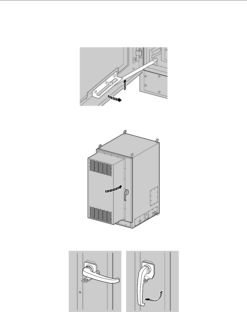
Closing the door
IP-RN 8000 Installation & Commissioning Guide 199
Closing the door
To close the door:
1. Lift the hinge locking bar with your foot to release the door-open lock.
2. Open the door handle by turning the handle in a clockwise direction and push the door closed.
3. Turn the door handle to the down position.
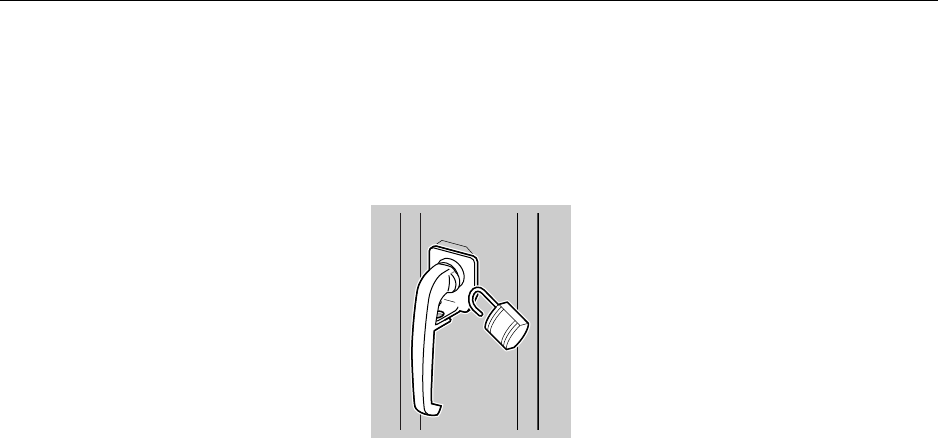
Appendix B ● Using the door
200 Release 2.0, 910056 Rev01d
Padlocking the door
To padlock the front door:
1. Ensure the door is closed and the handle is in the down position.
2. Open the padlock and insert it in the door-handle padlock hole.
3. Lock the padlock.
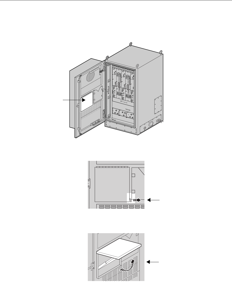
Opening the PC shelf
IP-RN 8000 Installation & Commissioning Guide 201
Opening the PC shelf
To open the PC shelf:
1. Locate the PC shelf on the inside of the front door.
2. Pull the lock on the PC shelf’s lower right corner out to the right.
3. Lift the PC shelf upright until it locks in the open position.
PC shelf
PC shelf lock
Lift upright

Appendix B ● Using the door
202 Release 2.0, 910056 Rev01d
Closing the PC shelf
To close the PC shelf, push in the support hinge under it to unlock the shelf and then fold down the PC shelf.
1. Push support hing in.
2. Fold PC shelf down.

IP-RN 8000 Installation & Commissioning Guide 203
Appendix C
Using access panels
About this appendix
This appendix contains access panel procedures used multiple times throughout the main
installation process. This appendix contains the following sections:
•Removing the power terminal access panel on page 204
•Re-installing the power terminal access panel on page 205
•Re-installing the right side cable access panel on page 207
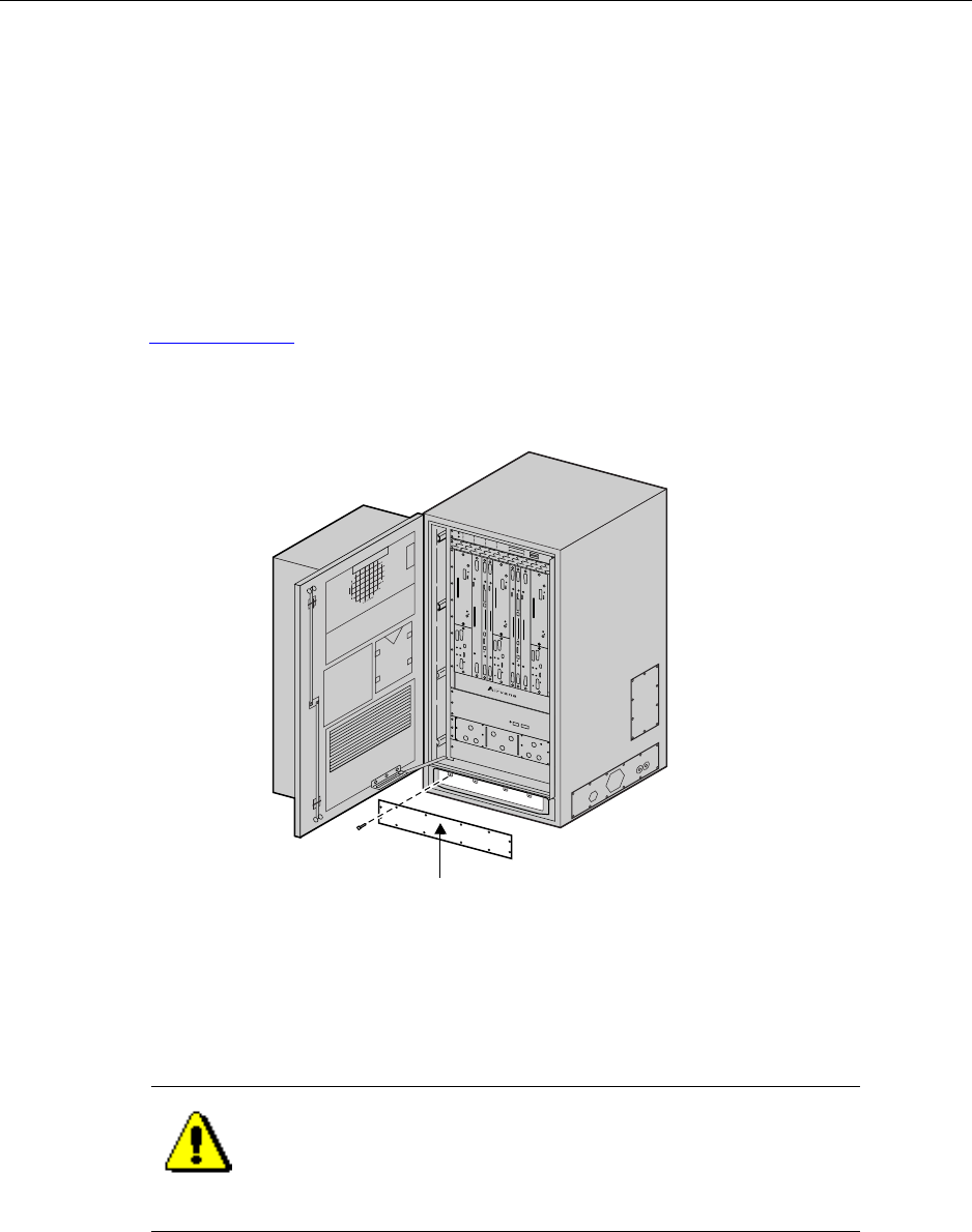
Appendix C ● Using access panels
204 Release 2.0, 910056 Rev01d
Removing the power terminal access panel
This procedure explains how to remove the power terminal access panel.
Requirements
• 5/32 inch tamper-resistant hex drive screw driver.
To remove the power terminal access panel:
1. Open the front door.
See Opening the door on page 198.
2. Locate the power terminal access panel on the cabinet.
3. Use the 5/32 inch tamper-resistant hex driver to remove all screws from the access panel.
Each screw has a rubber, sealing lock washer on its shank.
4. Carefully set aside the access panel and the screws with their rubber washers.
You will use these to reinstall the panel.
This procedure is complete.
CAUTION
Access panels must be handled carefully. If they are bent they
may not form a proper seal with the cabinet when they are
re-installed. An intact seal on the inside edge of the access panel
is required to ensure external environmental conditions are sealed
out.
Power terminal access panel
Front view, door open
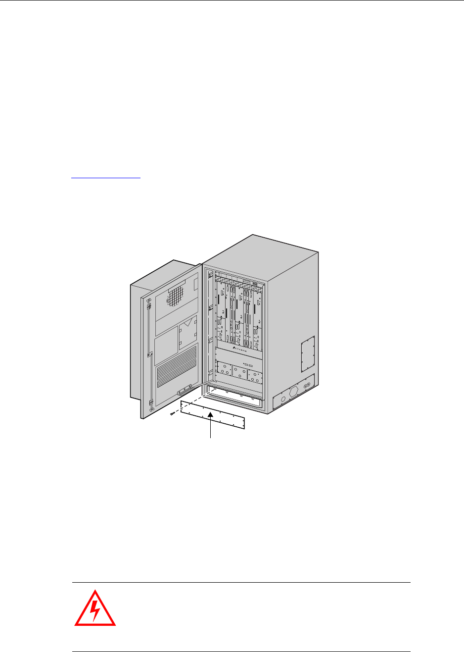
Re-installing the power terminal access panel
IP-RN 8000 Installation & Commissioning Guide 205
Re-installing the power terminal access panel
This procedure explains how to re-install the power terminal access panel.
Requirements:
• 5/32 tamper-resistant screw driver
• Thread tapping kit with 1/4-20 thread bit at 3/4 inch depth
To reinstall the power terminal access panel:
1. Open the front door.
See Opening the door on page 198.
2. Locate the power terminal access panel area on the cabinet.
3. Retrieve the access panel and the 11 tamper-proof screws and rubber washers that you set aside when
removing the panel.
4. Examine the inside edge of the access panel to ensure the access panel is undamaged.
The gasket on the inside edge must be intact to ensure a proper seal.
5. Position the access panel and start all screws by hand.
Be sure to thread the rubber sealing washer on the screw shank before inserting it into the access panel
screw hole.
WARNING
Screws should be started by hand. It is possible to damage the
thread in the cabinet if you use a hand tool or a power tool.
Damaged threads must be repaired or the cabinet will be
improperly sealed and the IP-RN 8000 can be damaged. Use a
thread tapping set to fixed damaged threads.
Power terminal access panel
Front view, door open

Appendix C ● Using access panels
206 Release 2.0, 910056 Rev01d
6. Use a torque wrench with a 5/32 inch tamper-resistant hex drive bit set to 18 inch-pounds to tighten all
screws evenly.
This procedure is complete.
WARNING
If access panels screws are not tightened with the correct torque,
electronic interface may occur causing equipment malfunction.
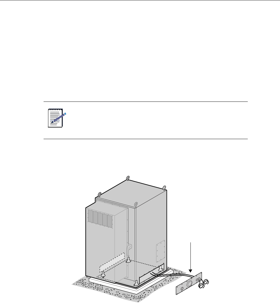
Re-installing the right side cable access panel
IP-RN 8000 Installation & Commissioning Guide 207
Re-installing the right side cable access panel
This procedure explains how to re-install the right side cable access panel.
Required tools and materials:
• 5/32 inch tamper-resistant hex drive screw driver
• 5/8 inch open ended wrench
• 11/16 open ended wrench
• Torque wrench with a 5/32 inch tamper-resistant hex drive bit
• Thread tapping set with bit for 1/4-20 threads at 3/4 inch depth
To reinstall the right-side cable-access panel:
1. Locate the right-side access panel.
2. Retrieve the 12 tamper-resistant screws and rubber washers that you set aside when removing the panel.
3. Examine the inside edge of the access panel to ensure the access panel is undamaged:
The gasket on the inside edge must be intact to ensure a proper seal.
4. Slide the access panel into place along the grounding wires.
If the access panel does not slide towards the cabinet along the grounding wires, loosen the nuts
securing the access panel to each grounding wire.
NOTE
Conduit and cables may already be installed into the access
panel.
Right access panel
Appendix C ● Using access panels
208 Release 2.0, 910056 Rev01d
5. Position the access panel and start all screws by hand.
Be sure to thread the rubber sealing washer on the screw shank before inserting it in the access panel
screw hole.
6. Use a torque wrench with a 5/32 inch tamper-resistant hex drive bit set to 18 inch-pounds to tighten all
screws evenly.
7. Re-seal the ground wires.
a. Examine the two ground wires that protrude through the side of the access panel.
Each ground wire has a rubber grommet and a 11/16 inch sealing net. The rubber grommets may be
in their proper location, tight against the access panel. Or, the rubber grommets may have been
pushed away from the access panel when the access panel was moved back into place.
b. For both ground wires, ensure the rubber grommet is pushed back snugly against the access panel.
c. Hand tighten the 11/16 inch nut, sealing the grommet in place.
d. Using the 11/16 inch open ended wrench, tighten the nuts on both grounding wires.
Wrench tighten snugly, but do not overtighten.
This procedure is complete.
WARNING
Screws should be started by hand. It is possible to damage the
thread in the cabinet if you use hand tool or a power tool.
Damaged threads must be repaired or the cabinet will be
improperly sealed and the IP-RN 8000 can be damaged. Use a
thread tapping set to fixed damaged threads.
WARNING
If access panels screws are not tightened with the correct torque,
electronic interface may occur causing equipment malfunction.
NOTE
Conduit must be installed to all openings on this access panel to
ensure equipment protection from the external environment. See
Planning conduit and grounding installation on page 53.

IP-RN 8000 Installation & Commissioning Guide 209
Glossary
1xEV-DO 1x Evolution-Data Only. A 3G Mobile Wireless technology based on CDMA
that offers high-speed, high-capacity wireless Internet connectivity, and is
optimized for packet data services. 1xEV-DO provides a peak data rate of
2.4 Mbps on the forward link within a single 1.25 MHz CDMA carrier.
1xRTT 1x Radio Transmission Technology. A 3G Mobile Wireless technology
based on CDMA that doubles the voice capacity of current CDMA mobile
systems, and adds packet data capability.
3G Third Generation. Generic name for mobile wireless systems used for
offering advanced voice and data services, the first two generations refer to
the existing analog and digital cellular networks respectively. W-CDMA,
1xRTT and 1xEV-DO are the most popular 3G standards.
3GPP A global standards body that is developing 3G standards for the W-CDMA
air interface technology.
3GPP2 A global standards body that is developing 3G standards for the CDMA2000
family of air interface technologies including 1xRTT and 1xEV-DO.
AirVista Airvana’s web-based network management system
Air Interface The Air Interface is the part of a mobile wireless standard that defines the
protocol enabling the subscriber terminal and the radio access network to
interoperate.
ATM A telecommunications method for relaying images, sound and text
simultaneously at very high speeds.
BTS Base Transceiver Station. Radio equipment that cellular operators need to
place at the center of each cell, usually simply called a base station.
BSC Base Station Controller. A wireless network equipment that controls Base
Stations.
carrier An electrical signal that emits at a continuous frequency and carriers data.
Information is encoded onto the carrier by changing the frequency,
amplitude, or phase of the signal (this process is called modulation). The
signal is extracted at the other end through demodulation. Carriers are
modulated and demodulated according to fixed protocols.
CDMA Code Division Multiple Access. A global Mobile Wireless technology based
on a method of sharing frequency among many users by encrypting each
user's signal using a different code.
cell The basic geographical unit of a cellular network, a cell is the area served by
a cell site. Its size varies depending on the terrain, capacity demands, and
strength of the signal from the cell site.
cell site A transmitter/receiver location in a cellular network. The cell site establishes
radio links between the wireless network and the user. The site contains an
antenna tower, transmission radios, and radio controllers.
channel A pair of radio frequencies. One frequency is used for sending and the other
for receiving.

Glossary
210 Release 2.0
cluster Two or more nodes bundled together to appear as a single system. Clusters can be
used to provide near continuous access to application services, including databases,
Web services, and file services.
Ethernet The world's most widely deployed standard for Local Area Networking; it operates at
10, 100,1,000 and 10,000 Mbps.
Frame Relay A widely used connection oriented packet-networking technology.
IP-RN 8000 IP-Radio Node 8000. Airvana’s Base Transceiver Station.
IP-RNC 8500 IP-Radio Network Controller. Airvana’s Base Station Controller.
IS-95 The industry standard name for CDMA Mobile wireless technology.
Metropolitan Ethernet A low cost Wide Area Network technology that transports user data as Ethernet
frames over an optical network, typically in a metropolitan area.
PSK Phase Shift Keying; a modulation technique.
QAM Quadrature Amplitude Modulation; a multi-level modulation technique.
QPSK Spectrally efficient modulation technique that breaks the information path into two
parts called the “in phase” and the “quadrature phase” components. The combination
of these two signals creates one of four unique symbols that are then used to modulate
the phase of the carrier.
Radio Access Network The part of a wireless network comprised of Base Stations and Base Station
Controllers.
VoIP Voice over IP. A method of sending voice information over a packet-switched
network, such as the Internet, using TCP/IP.
VPN Virtual Private Network. A networking technology used to send data securely over
public data networks.
WAP Wireless Application Protocol. Stack of protocols designed for sending simplified
Web pages to wireless devices. It replaces web protocols with its own, and requires
that pages be written in WML instead of HTML.
W-CDMA Wideband CDMA. A 3G CDMA system that is an evolution of the current GSM
network. W-CDMA operates on a 5 MHz channel and supports voice and data
services.

IP-RN 8000 Installation & Commissioning Guide 211
Acronyms
1xEV-DO 1x Evolution-Data Only standard
1xDOM 1x Evolution Data Only module
1xRTT 1x Radio Transmission Technology
3G Third Generation
3GPP Third Generation Partnership Project
AIU Antenna Interface Unit
ATM Asynchronous Transfer Mode
BIO Base Input/Output
BIO/SC Base Input Output/System Controller
BIO TM Base Input/Output Transition Module
BTS Base Transceiver Station
BSC Base Station Controller
CDMA Code Division Multiple Access
CLI Command Line Interface
CTIA Cellular Telecommunications Industry Association
FTP File Transfer Protocol
GPS Global Positioning System
GSM Global System for Mobile Communications
LED Light Emitting Diode
HSC Hot Swap Controller
IP-RAN IP Radio Access Network
IP-RN 8000 IP-Radio Node
IP-RNC 8500 IP-Radio Network Controller
ITU International Telecommunications Union
PA Power Amplifier
PCS Personal Communications System
PDU Power Distribution Unit
PSK Phase Shift Keying
RNSM Radio Node Server Module
SC System Controller
SC TM System Controller Transition Module
TDMA Time Division Multiple Access

Acronyms
212 Release 2.0
TIA Telecommunications Industry Association
QAM Quadrature Amplitude Modulation
RF Radio Frequency
RM Radio Module
TFU Timing Frequency Unit
VoIP Voice over IP
VPN Virtual Private Network
WAP Wireless Application Protocol
W-CDMA Wideband CDMA

IP-RN 8000 Installation & Commissioning Guide 213
Index
Numerics
10 MHz out 22
1xDOM
components 25
installing 122
LEDs 26
physical specifications 195
redundant 20
reset buttons 26
slots 12
2U 4, 10
66-block
see backhauls 79
A
access panels
antenna
optional 10
standard 10
cable
left side 10
right side 10
cable access
re-installing 207
gasket washer 194
power terminal 10
removing 204
punch block
punch block
access panel 10
screws 194
surge protection bar 10
understanding 9
user equipment 4, 10
acess panels
power terminal
re-installing 205
AIUcables 35
compenents 17
connecting to Sector Radio Kit 113
description 4
ESD 19
front view 3
sectors 19
understanding 13
Alarm Unit 29
components 29
description 4
front view 3
LEDs 30
alarms 192
alpha
slots 12
altitude 192
anchoring bolts 58
antenna access panel 8
right side view 5
antenna cables 7, 8
exiting cabinet 8
inside cabinet 8
Antenna Interface Unit
see AIU 17
antennas
access panel options 91
cable lables and connectors 88
connecting 85, 96
connecting to surge supresion bar 97
GPS
description 34
installation process 86
installing 40
RF description 34
Rox system
installing 94
B
back view 7
backhaul
network diagram 2
routing into cabinet 64
backhaul cable access port
right side view 5
backhaul punch block
description 5
front view 3
understanding 32
backhaul switch
understanding 32
backhauls
access to punch block 76
cabling in cabinet 77
connecting 40, 73
description 34
installation process 74, 146
loopback, see loopbacks 158
punch block
detail 82

Index
214 Release 2.0, 910056 Rev01d
pin out 80
wiring 79
understanding 75
Base Input Output/System Controller
see BIO/SC 22
beta slots 12
BIO/SC 22
components 22
installing 119
LEDs 24
physical specifications 195
redundant 20
reset button 15, 24
slots 12
bottom slots 11
C
cabinet
anchor bolts 194
anchoring 50
bolting to pad 62
description 4
front view 3
installation process 50
installing 40, 49
lifting 60
lowering 61
placing on pad 58
preparing for installation 50
right side view 5
unbolting from palette 57
unpacking 54
chassis power 28
CLIconnection 35
craft port 24
diagnostic mode 163
serial
connection process 132
establishing connection 135
redundant systems 132
terminal settings 136
understanding 132
telnet 133
commissioning
completing the process 188
requirements 129
the process 128
concrete pad 58
conduit 50, 193
planning 53
craft
Ethernet 24, 35
Ethernet, see Ethernet
craft 137
port 129
serial port 24
D
danger 45
DB-9 129
depth 192
diagnostic mode in CLI 163
Digital Module Kit
installation 104
redundancy 20
slots 12
understanding 19
dimensions 192
disposal 45, 46
document holder
right side view 5
door
closing 199
description 4
front view 3
lock-open bar 6
right side view 5
opening 198
padlocking 200
right side view 5
E
earthquake 194
electro static discharge 19
ESD 19, 44
Ethernet
backhuals
not switched 33
craft 24, 35
configuring IP 137
connecting 138
craft connection
understanding 133
cross-over cable 129
F
fan power 28

Index
IP-RN 8000 Installation & Commissioning Guide 215
Fan Unit 31
air flow 37
components 31
description 4
front view 3
LEDs 31
front view 3
FTP 129
sofware update 142
G
gamma
slots 12
GPS 2
antennas 7
cables 194
GR-1089 compliance 44
ground
connections
description 34
connectors
rear 7, 8
installing 49
third wire 66
ground cable 193
ground coil
cabinet 6
lightning 6
right side view 5
grounding
cabinet 67
planning 53
understanding 33
warning 47
H
heat exchange 192
exhaust
right side view 5
intake
right side view 5
heat exchange power 28
Heat Exchanger 37
height 192
humidity 192
HyperTerminal 129
I
indoor installation 52
input drop out time 193
installation
and commissioning, understanding 40
before you install 40
the process 40
insulation pad 59
IP Ethernet craft 137
L
laptop
Ethernet 129
lifting hooks 8
description 4
front view 3
right side view 5
lightning
warning 46
loading 192
locking door 200
loopbacks
Ethernet 162
understanding 160
internal test 166
running test 164
T1/E1 161
testing
the process 158
understanding 159
M
main power 28
module enclosure power 28
module slots
description 4
front view 3
modules
installation process 104
installing 40, 103
physical specifications 195
slots 12
N
network 2
planning 44

Index
216 Release 2.0, 910056 Rev01d
P
PA components 16
installing 105
LEDs 17
physical specifications 195
slots 12
palette 57
PC shelf
head exchange vents 6
opening 201
right side view 5
PDSN 2
PDU
components 27
description 4
front view 3
power
cable 193
installing 49
routing into cabinet 64
supply
connecting 65
description 34
testing 69
switches 28
terminal connecting 66
Power Amplifier
see PA 16
power cable access port
right side view 5
Power Distribution Unit
see PDU 27
power terminal 4
power terminal access panel 10
description 4
powering on
procedure 126
powering on the node 40
punch block
backhaul wiring 79
R
Radio Module
see RM 14
radio sectors
understanding 13
ratings 192
receiving 44
redundancy
Digital Module Kit 20
RF antennas 7
cables 194
right side view 5
RM 14
components 14
connecting to PA 111
installing 108
LEDs 15
physical specifications 195
slots 12
RNC-8500 2
Rox System 8
installed 7
RX0
RM 15
RX0 (Sample)
RM 15
RX1
RM 15
RX1 (Sample)
RM 15
S
safety 45
scripts
understanding 146
Sector Radio Kit 14
connecting to AIU 113
installation 104
understanding 13
Sector Radio Kits
slots 12
sectors
alpha, beta, gamma 12
security
locking door 200
seismic 194
serial port 24, 129
shipping 44
side ground connectors
right side view 5
site planning and construction 40
site planning and construction 44
slots
numbering 11
snow 192

Index
IP-RN 8000 Installation & Commissioning Guide 217
software update
activating release 144
requirements 129
the process 140
transferring 142
specifications 191
cable access ports 193
connectors, screws, nuts, bolts 194
earthquake/sisimic 194
grounding connection 193
modules 195
physical/environmental 192
power 193
spectrum analyzer 129
surge protection
understanding 33
surge protection bar
access panel 10
surge supression bar 7, 8
detail 97
T
T1/E1
backhauls 160
see loopbacks 161
tamper resistent screwdriver 194
tech-on-site switch
description 4
front view 3
temperatue 192
temperature 37
terminal
connection 35
settings 136
terminal emulation 129
testsEthernet, see loopbacks
Ethernet 160
internal loopback 166
see loopbacks 158
TFU 21
components 21
installin 116
LEDs 22
physical specifications 195
redundant 20
slots 12
Timing Frequency Unit
see TFU 21
top slots 11
TX (Sample)
PA 17
TX (to AIU)
PA 17
U
UL 192
user equipment 4, 10
V
voltage 193
W
warning 45
weight 192
width 192
wind 192
Windows 98 129

Index
218 Release 2.0, 910056 Rev01d