CommScope Technologies IPBTS-C30-1900 CDMA 1xEVDO Base Transceiver Station User Manual Manual
CommScope Technologies LLC CDMA 1xEVDO Base Transceiver Station Manual
UserManual.wiki
>
CommScope Technologies
>
IPBTS C30 1900 User Manual
Manual
Navigation menu
Upload a User Manual
Namespaces
Wiki Guide
HTML
PDF
Info
Views
User Manual
Discussion / Help
Navigation


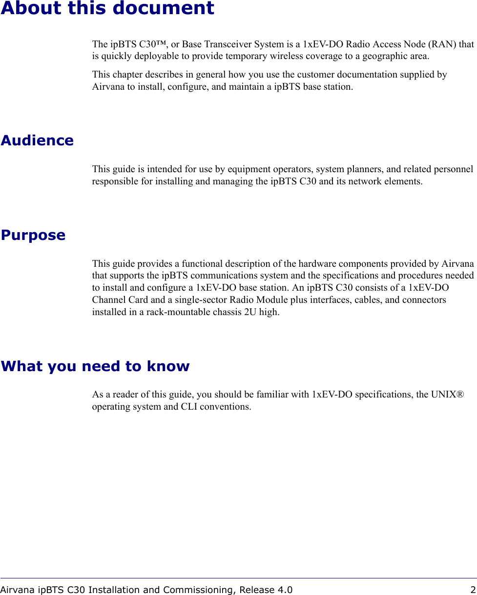
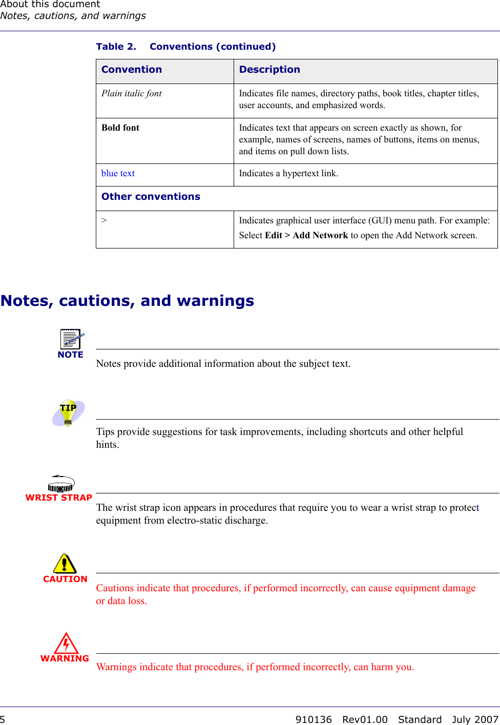
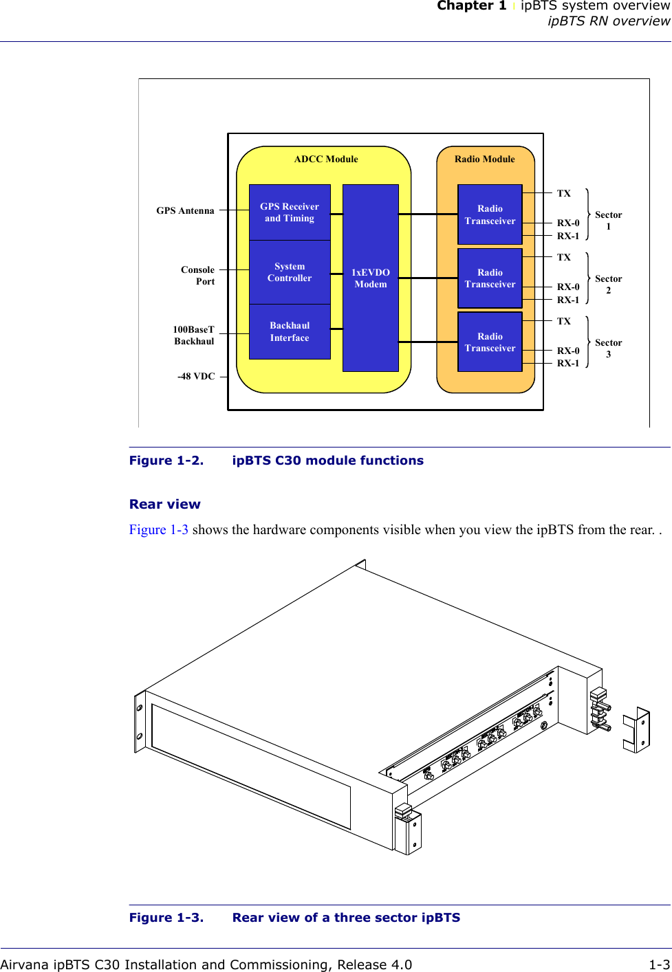
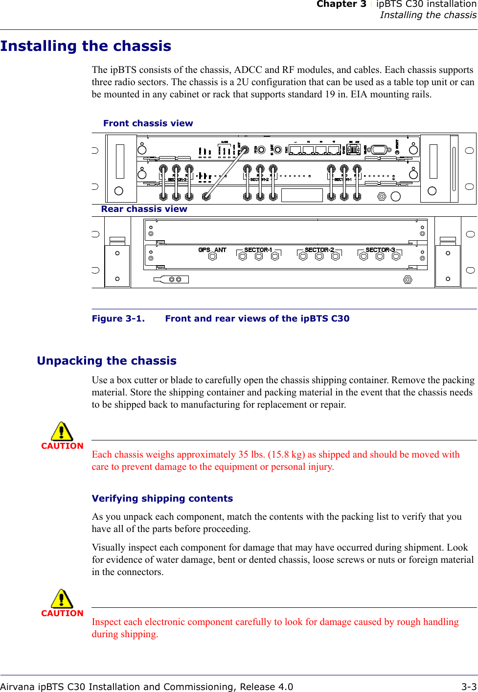
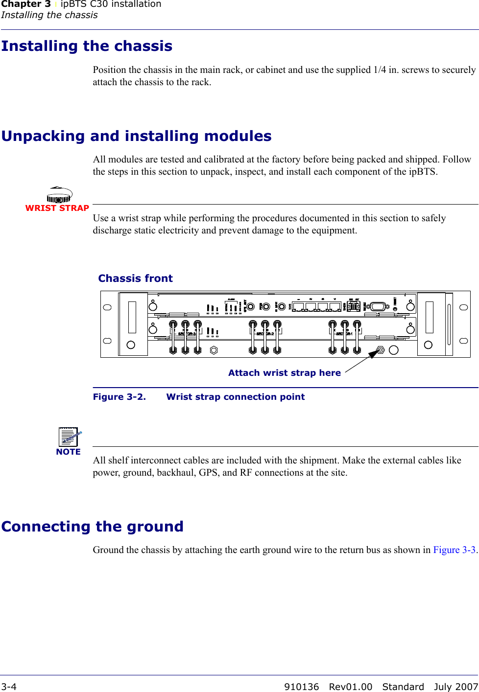
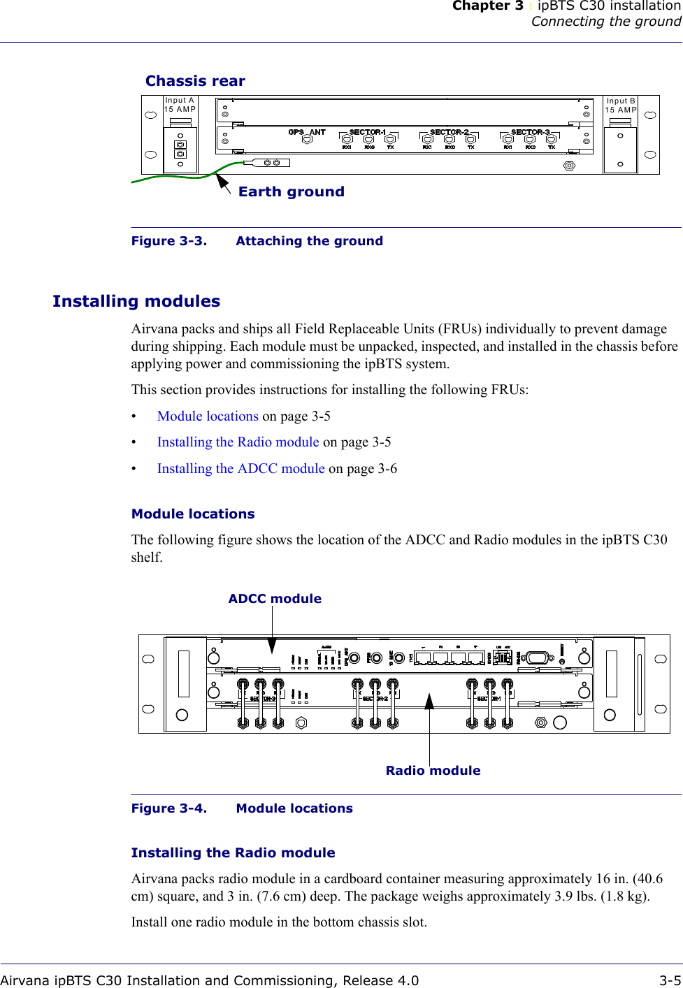
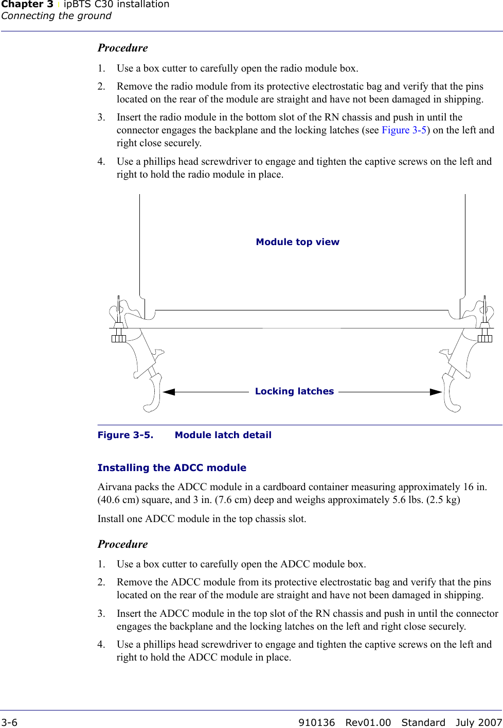
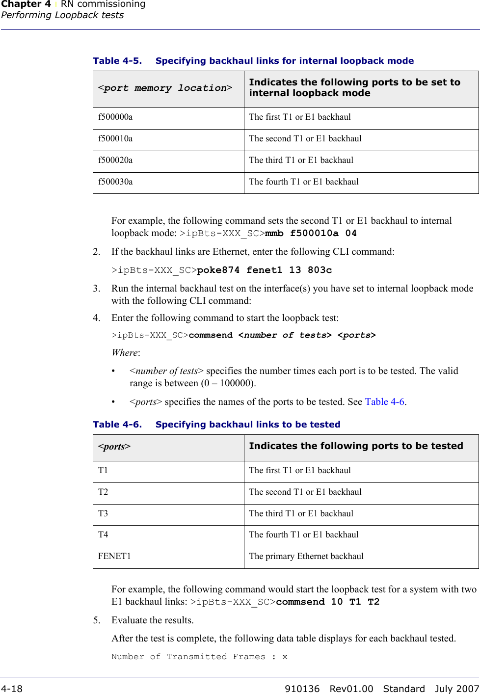
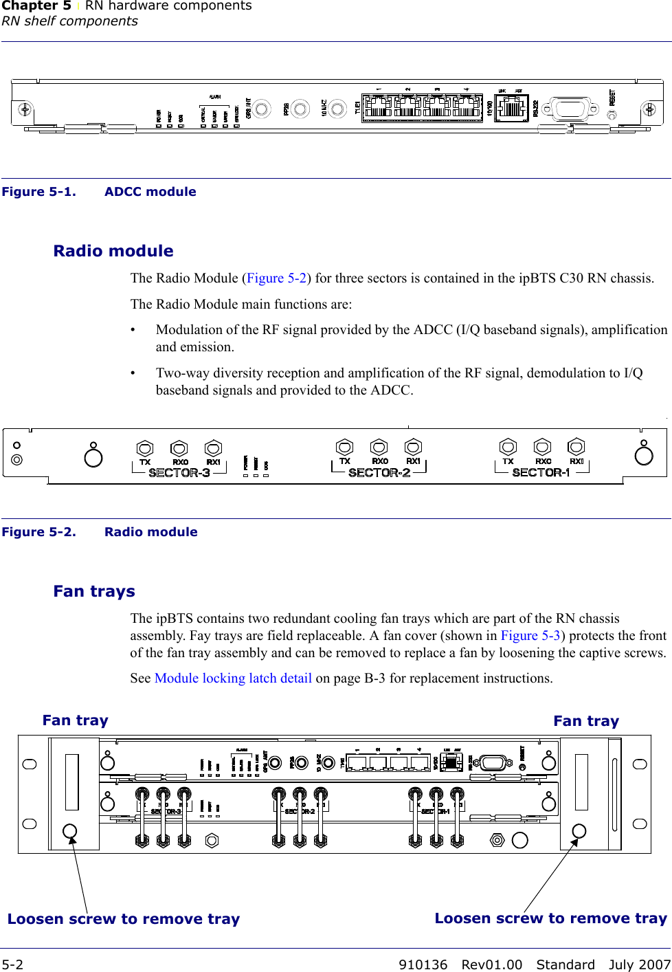
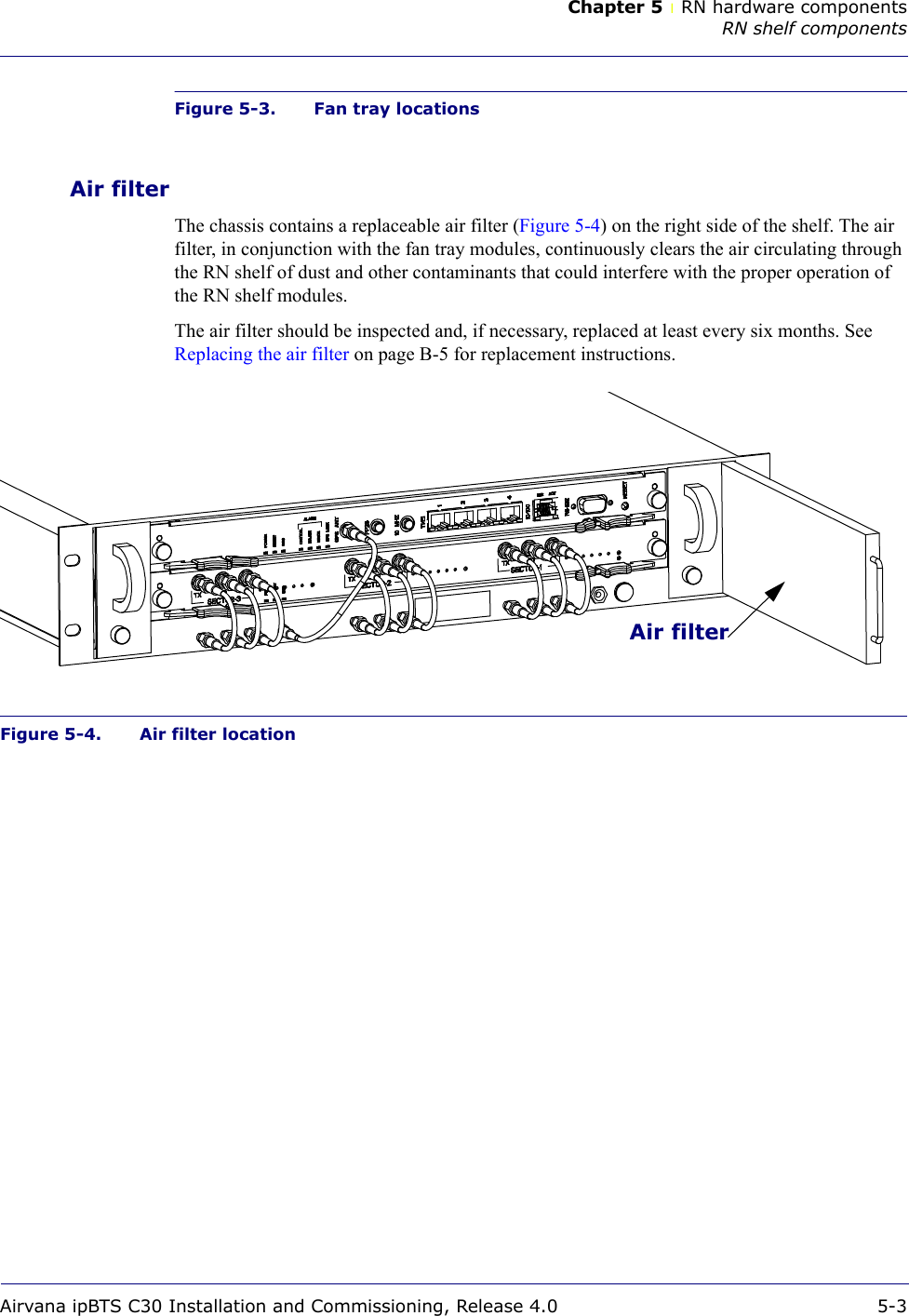
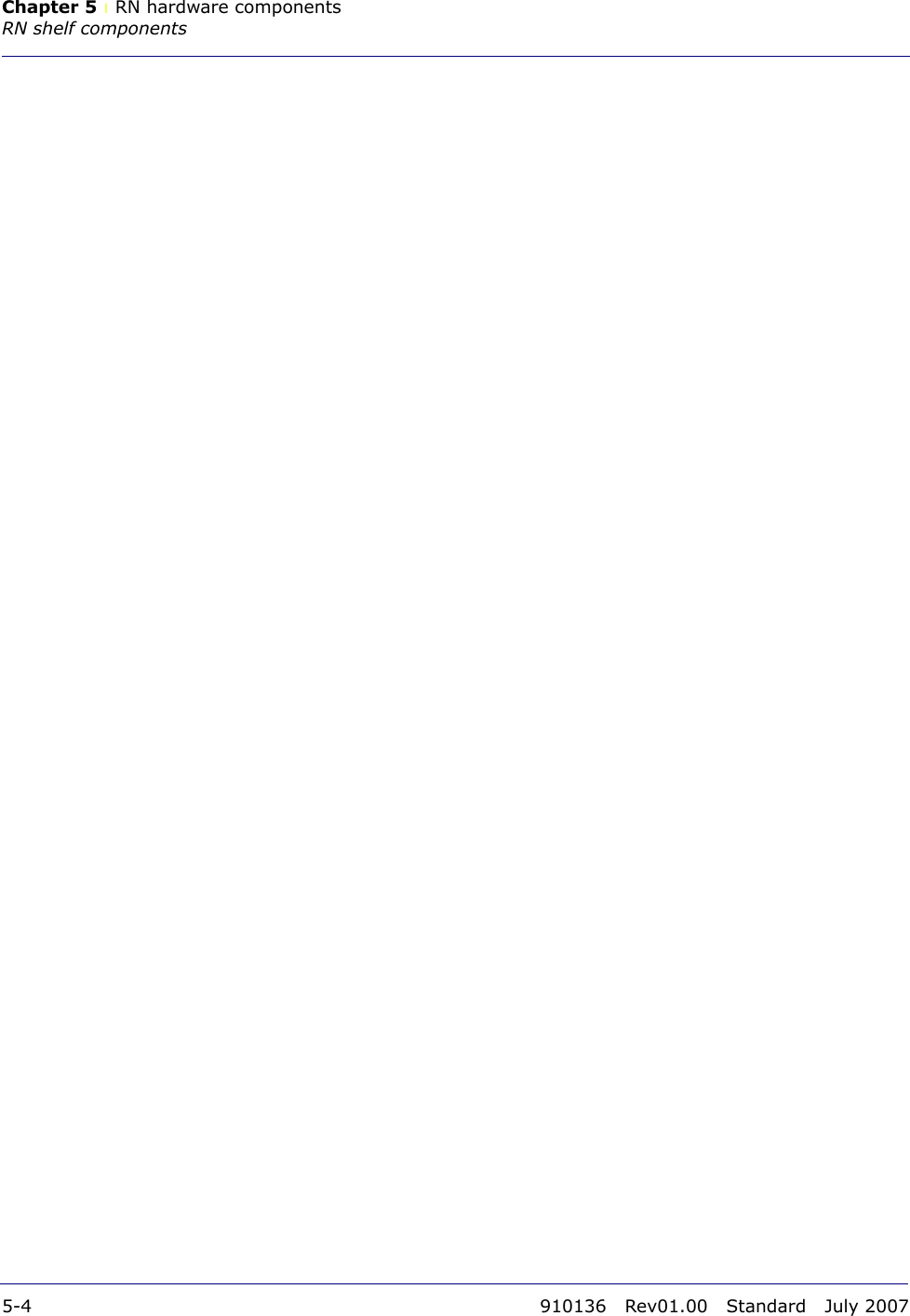
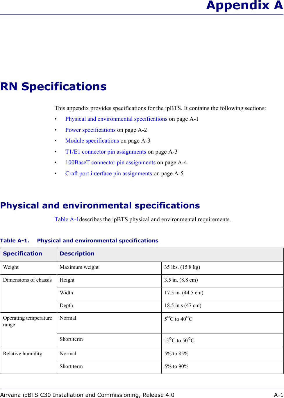
![About this documentConventionsAirvana ipBTS C30 Installation and Commissioning, Release 4.0 4ConventionsThis guide uses the following text conventions, as applicable.Table 2. ConventionsConvention DescriptionSyntax symbols< > Enclose a required parameter or set of parameters. For example:>band-class <class><class> is a required parameter.< > Enclose a named keyboard key. For example:Press <ENTER> to continue.You must press the Enter key to continue.[ ] Enclose an optional parameter or set of parameters. For example:>activate image <version> [reboot][reboot] is an optional parameter. | Separates items on a list of parameters, only one of which can be used. For example:>channel-included <yes|no>A valid command is:>channel-included yesFont usageBold CLI input font Indicates text that must be entered exactly as shown. For example:Enter ping 192.23.10.12.Italic CLI input font Indicates a variable parameter for which you must provide an actual value. For example:>authentication key <aukey><aukey> is a variable parameter. A valid command is:>authentication key 9782503000Plain CLI output font Indicates system output in a command line or system-generated file. For example:IP address 192.23.10.12 is alive.Italic CLI output font Indicates a variable in system output in a command line or system-generated file. For example:Installation of release <release> is complete.](https://usermanual.wiki/CommScope-Technologies/IPBTS-C30-1900/User-Guide-834705-Page-17.png)