CommScope Technologies IPBTS-C30-1900 CDMA 1xEVDO Base Transceiver Station User Manual Manual
CommScope Technologies LLC CDMA 1xEVDO Base Transceiver Station Manual
Manual

Confidential & Proprietary
Cover
ipBTS C30 Installation and
Commissioning
Release 4.0
910136 Rev01.00 Standard July 2007

ii 910136 Rev01.00 Standard July 2007

Airvana ipBTS C30 Installation and Commissioning, Release 4.0 iii
ipBTS C30 Installation and Commissioning

iv 910136 Rev01.00 Standard July 2007
Copyright © 2007 Airvana, Inc. All rights reserved.
Airvana is a registered trademark of Airvana, Inc. (“Airvana”). AirVista is a trademark of Airvana. All
other trademarks are trademarks of their respective owners.
This document contains information that is the property of Airvana. This document may not be copied,
reproduced, reduced to any electronic medium or machine readable form, or otherwise duplicated, and the
information herein may not be used, disseminated or otherwise disclosed, except with the prior written
consent of Airvana.
THE SPECIFICATIONS AND INFORMATION REGARDING THE PRODUCTS IN THIS MANUAL
ARE SUBJECT TO CHANGE WITHOUT NOTICE. ALL STATEMENTS, INFORMATION, AND
RECOMMENDATIONS IN THIS MANUAL ARE BELIEVED TO BE ACCURATE BUT ARE
PRESENTED WITHOUT WARRANTY OF ANY KIND, EXPRESS OR IMPLIED. USERS MUST
TAKE FULL RESPONSIBILITY FOR THEIR APPLICATION OF ANY PRODUCTS.
THE SOFTWARE LICENSE AND LIMITED WARRANTY FOR THE ACCOMPANYING PRODUCT
ARE SET FORTH IN THE INFORMATION PACKET THAT SHIPPED WITH THE PRODUCT AND
ARE INCORPORATED HEREIN BY REFERENCE. IF YOU ARE UNABLE TO LOCATE THE
SOFTWARE LICENSE OR LIMITED WARRANTY, CONTACT YOUR AIRVANA SALES
REPRESENTATIVE FOR A COPY.

Airvana ipBTS C30 Installation and Commissioning, Release 4.0 v
AIRVANA, INC. SOFTWARE LICENSE AGREEMENT
READ CAREFULLY BEFORE USING THIS SOFTWARE
This is a legal agreement between you, the end user ("CUSTOMER") and Airvana, Inc., its affiliates and subsidiaries
(collectively "AIRVANA"). This Agreement is part of a package (the "PACKAGE") that also includes, as applicable,
executable files that can be installed from one or more CD-ROMs (referred to herein as the "SOFTWARE") and certain
written materials (the "DOCUMENTATION"). Any patch, update, upgrade, modification or other enhancement provided
by AIRVANA with respect to the SOFTWARE or the DOCUMENTATION shall be included within the meanings of those
terms, for the purposes of this Agreement, except to the extent expressly provided below.
BY DOWNLOADING OR INSTALLING THE SOFTWARE, CUSTOMER ACKNOWLEDGES THAT CUSTOMER
HAS READ ALL OF THE TERMS AND CONDITIONS OF THIS AGREEMENT, UNDERSTANDS THEM, AND
AGREES TO BE BOUND BY THEM. CUSTOMER UNDERSTANDS THAT, IF CUSTOMER PURCHASED THE
PACKAGE FROM AN AUTHORIZED RESELLER OF AIRVANA, THAT RESELLER IS NOT AIRVANA’S AGENT
AND IS NOT AUTHORIZED TO MAKE ANY REPRESENTATIONS, CONDITIONS OR WARRANTIES,
STATUTORY OR OTHERWISE, ON AIRVANA’S BEHALF NOR TO VARY ANY OF THE TERMS OR
CONDITIONS OF THIS AGREEMENT.
If CUSTOMER does not agree to the terms of this Agreement, CUSTOMER shall promptly return the entire PACKAGE to
the place CUSTOMER obtained it for a full refund of the software license fee. If CUSTOMER should have any difficulty
in obtaining such refund, CUSTOMER can contact AIRVANA at 978-250-3000.
LICENSE GRANT. AIRVANA grants to CUSTOMER a personal, nonexclusive license (i) to use the SOFTWARE in
object code format solely on a single server unit owned or leased by CUSTOMER or otherwise embedded in equipment
provided or sold by AIRVANA to CUSTOMER and (ii) to use the accompanying DOCUMENTATION. CUSTOMER may
transfer its copy of the SOFTWARE together with its DOCUMENTATION on a permanent basis, provided that
CUSTOMER notifies AIRVANA as to the name and address of the recipient of its copy and that such recipient agrees in
writing to the terms and conditions of this Agreement. CUSTOMER may not network the SOFTWARE or otherwise use it
on more than one computer or computer terminal at the same time. CUSTOMER may make one (1) copy of the
SOFTWARE in machine readable object code format for archival purposes for use by CUSTOMER in the event that the
SOFTWARE shall become inoperative, and provided CUSTOMER affixes to such copy all copyright, confidentiality, and
proprietary notices that appear on the original SOFTWARE.
OWNERSHIP OF THE SOFTWARE AND DOCUMENTATION; RESTRICTIONS ON USE. The SOFTWARE
and the DOCUMENTATION are protected by United States, Canadian and other applicable laws and by international
treaty provisions. Any rights not expressly granted herein are reserved to AIRVANA or its Suppliers. CUSTOMER agrees
that the SOFTWARE and DOCUMENTATION, including the specific design and structure of individual programs,
constitute trade secrets and/or copyrighted material of AIRVANA or its Suppliers. CUSTOMER agrees not to disclose,
provide, or otherwise make available such trade secrets or copyrighted material in any form to any third party without the
prior written consent of AIRVANA. CUSTOMER agrees to implement reasonable security measures to protect such trade
secrets and copyrighted material. Title to the SOFTWARE and DOCUMENTATION and patents, copyrights and all other
property rights applicable thereto, shall remain solely and exclusively with AIRVANA or its Suppliers, and CUSTOMER
shall not take any action inconsistent with such title.
ADDITIONAL RESTRICTIONS. Except as expressly authorized above, CUSTOMER may not cause or permit the
disclosure, copying, renting, licensing, sublicensing, leasing, dissemination or other distribution of the SOFTWARE or the
DOCUMENTATION by any means or in any form, without the prior written consent of AIRVANA. You may not use the
SOFTWARE to conduct a service bureau or similar business for the benefit of third parties. You may not modify, enhance,
supplement, create derivative work from, adapt, translate, reverse engineer, decompile, disassemble or otherwise reduce
the SOFTWARE to human readable form.

vi 910136 Rev01.00 Standard July 2007
TERM. This LICENSE is effective until terminated. CUSTOMER may terminate this LICENSE at any time by
destroying all copies of the SOFTWARE and the DOCUMENTATION. This LICENSE will terminate immediately
without notice from AIRVANA if CUSTOMER fails to comply with any provision of this LICENSE. Upon termination,
CUSTOMER must either, at AIRVANA’s direction, return or destroy all copies of SOFTWARE, including any
DOCUMENTATION. CUSTOMER agrees that it will not engage in the reverse engineering, disassembling,
decompilation or any other alteration of the SOFTWARE; provided, however, that if reproduction of the code and
translation of its form are necessary to obtain the information required to achieve the interoperability of the SOFTWARE
with other programs, CUSTOMER shall inform AIRVANA in writing accordingly and AIRVANA shall notify
CUSTOMER within twenty (20) business days from receipt of CUSTOMER’s request that: (i) AIRVANA will perform
the work in order to achieve such interoperability and charge an reasonable expense allowance for such work to
CUSTOMER, or (ii) CUSTOMER itself is entitled to undertake those actions, but only to the extent required to achieve
the interoperability of the SOFTWARE with other programs.
LIMITED WARRANTY
SOFTWARE. AIRVANA warrants that for a period of ninety (90) days (the “WARRANTY PERIOD”) from the date
of delivery from AIRVANA: (i) the media on which the SOFTWARE is furnished will be free of defects in materials and
workmanship under normal use, and (ii) the SOFTWARE substantially conforms to the accompanying
DOCUMENTATION. If during the WARRANTY PERIOD, the SOFTWARE is non-compliant with the above
warranty, AIRVANA’s exclusive liability, and CUSTOMER’s sole and exclusive remedy, shall be, at AIRVANA’s option,
to either (a) repair or replace such nonconforming SOFTWARE or (b) refund to CUSTOMER that portion of the license
fee paid by CUSTOMER allocable to such nonconforming SOFTWARE; provided however, that AIRVANA shall have
no obligations pursuant to this limited warranty unless AIRVANA shall have received from CUSTOMER during the
WARRANTY PERIOD written notice from CUSTOMER of the alleged nonconformance and the circumstances
underlying CUSTOMER’s claim. This limited warranty applies: (i) to the initial purchaser only and may be acted upon
only by the initial purchaser, and (ii) does not apply to any patch, update, upgrade, modification, or other enhancement
provided by AIRVANA at no extra charge as part of the PACKAGE, which are provided on an AS IS basis only.
RESTRICTIONS. AIRVANA’s warranty obligations are expressly conditioned upon (i) the SOFTWARE being
properly installed, used and maintained in accordance with the DOCUMENTATION, (ii) the SOFTWARE not being
subjected to unusual mechanical stress or unusual electrical or environmental conditions, (iii) the SOFTWARE not being
subjected to misuse, accident or neglect, and (iv) the SOFTWARE not being altered or modified, unless such alteration
or modification has been authorized in writing or performed by AIRVANA. AIRVANA DOES NOT WARRANT THAT
THE SOFTWARE WILL OPERATE IN ANY SPECIFIC COMBINATION THAT MAY BE SELECTED FOR USE BY
CUSTOMER, OR THAT THE OPERATION OF THE SOFTWARE WILL BE UNINTERRUPTED OR ERROR FREE,
OR THAT ALL NONCONFORMANCE OR DEFECTS WILL BE REMEDIED. ADDITIONALLY, AIRVANA
SHALL HAVE NO WARRANTY OBLIGATIONS FOR ANY FAILURE OF THE SOFTWARE TO CONFORM TO
THE DOCUMENTATION RESULTING FROM THE COMBINATION OF ANY SOFTWARE WITH HARDWARE
AND/OR SOFTWARE NOT SUPPLIED BY AIRVANA OR FROM THE FAILURE BY CUSTOMER TO TIMELY
OR PROPERLY IMPLEMENT ANY DESIGN OR ENGINEERING CHANGE ORDERS WHEN REQUESTED TO
DO SO BY AIRVANA. If SOFTWARE reported as defective or nonconforming by CUSTOMER during the
WARRANTY PERIOD is not so defective or nonconforming, AIRVANA may, at its option, charge CUSTOMER for
any labor provided and expenses incurred by AIRVANA in connection with such determination, at AIRVANA’s then
current rates.

Airvana ipBTS C30 Installation and Commissioning, Release 4.0 vii
DISCLAIMER OF WARRANTY. EXCEPT AS SPECIFIED IN THE EXPRESS LIMITED WARRANTY
PROVISION ABOVE, THE WARRANTIES OF AIRVANA HEREIN ARE EXCLUSIVE AND ARE GIVEN BY
AIRVANA AND ACCEPTED BY CUSTOMER IN LIEU OF ANY AND ALL OTHER WARRANTIES, WHETHER
EXPRESS, IMPLIED OR ARISING FROM CUSTOM OR TRADE USAGE, INCLUDING, WITHOUT
LIMITATION, THE IMPLIED WARRANTIES OF MERCHANTABILITY, FITNESS FOR A PARTICULAR
PURPOSE, TITLE AND NON-INFRINGEMENT, ALL SUCH OTHER WARRANTIES BEING HEREBY
EXPRESSLY AND IRREVOCABLY DISCLAIMED BY AIRVANA AND WAIVED BY CUSTOMER. Some
jurisdictions do not allow limitations on how long an implied warranty or condition lasts, so the above limitation may
not apply to CUSTOMER. This limited warranty gives CUSTOMER specific legal rights, and CUSTOMER may also
have other rights which vary from jurisdiction to jurisdiction.
LIMITATION OF LIABILITY AND REMEDIES. TO THE EXTENT PERMITTED BY APPLICABLE LAW,
NEITHER AIRVANA NOR ITS SUPPLIERS SHALL BE LIABLE TO CUSTOMER OR ANY THIRD PARTIES FOR
ANY LOST REVENUE, PROFIT OR DATA, TECHNOLOGY OR SERVICES OR FOR SPECIAL, INDIRECT,
CONSEQUENTIAL, INCIDENTAL, OR PUNITIVE DAMAGES ARISING OUT OF OR IN CONNECTION WITH
THIS LICENSE, THE SOFTWARE OR DOCUMENTATION, EVEN IF AIRVANA OR ITS SUPPLIERS HAVE
BEEN ADVISED OF THE POSSIBILITY OF SUCH DAMAGES. SUCH LIMITATION OF LIABILITY SHALL
APPLY REGARDLESS OF THE CAUSE OF ACTION UNDER WHICH SUCH DAMAGES ARE SOUGHT,
INCLUDING, WITHOUT LIMITATION, BREACH OF CONTRACT, NEGLIGENCE, BREACH OF WARRANTY,
INDEMNIFICATION, STRICT LIABILITY OR OTHER TORT.
IN NO EVENT SHALL AIRVANA’S OR ITS SUPPLIERS' LIABILITY TO CUSTOMER FOR DAMAGES OF ANY
NATURE ARISING OUT OF OR IN CONNECTION WITH THIS LICENSE, REGARDLESS OF THE CAUSE OF
ACTION SET FORTH ABOVE, EXCEED THE TOTAL LICENSE FEES FOR THE SOFTWARE PAID BY
CUSTOMER. Some jurisdictions do not allow the exclusion or limitation of special, incidental, consequential, indirect
or exemplary damages, or the limitation of liability to specified amounts, so the above limitation or exclusion may not
apply to CUSTOMER.
GENERAL PROVISIONS. This LICENSE shall be governed by and construed in accordance with the laws of the
Commonwealth of Massachusetts, United States of America, as if performed wholly within the state; excluding (1) the
United Nations Convention on Contracts for the International Sale of Goods; (2) the1974 Convention on the Limitation
Period in the International Sale of Goods (the "1974 Convention"); and (3) the Protocol amending the 1974 Convention,
done at Vienna April 11, 1980. The original of this LICENSE has been written in English. The parties hereto waive any
statute, law, or regulation that might provide an alternative law or forum or to have this LICENSE written in any
language other than English. If any provision of this LICENSE is held to be excessively broad as to scope, activity,
subject, or otherwise so as to be unenforceable at law, such provision shall be constructed by limiting or reducing it so as
to be enforceable to the maximum extent compatible with the applicable law as it shall then appear. If any portion hereof
is found to be void or unenforceable, the remaining provisions of this LICENSE shall remain in full force and effect.
This LICENSE constitutes the entire agreement between the parties with respect to the use of the SOFTWARE and the
DOCUMENTATION. This LICENSE may not be modified except by a written agreement signed by authorized
representatives of both parties. A waiver by either party of its rights hereunder shall not be binding unless contained in a
written agreement signed by an authorized representative of the party waiving its rights.
The SOFTWARE and DOCUMENTATION are controlled by the export laws and regulations of the United States. In the
event CUSTOMER exports the SOFTWARE or the DOCUMENTATION from the country in which CUSTOMER first
received it, CUSTOMER assumes the responsibility for compliance with all applicable export and re-export regulations,
as the case may be.

viii 910136 Rev01.00 Standard July 2007
The SOFTWARE and DOCUMENTATION are “commercial items” as that term is defined in 48 C.F.R. 2.101 (October
1995) consisting of “commercial computer software” and “commercial computer software documentation” as such
terms are used in 48 C.F.R. 227.7202-1, 227.7202-3 and 227.7202-4 (June 1995). Absent a written agreement to the
contrary, the U.S. Government's rights with respect to such SOFTWARE or DOCUMENTATION are limited by the
terms of this Agreement, pursuant to FAR 12.212(a) and/or DFARS 227.7202-1(a), as applicable.
CUSTOMER shall be responsible for and shall pay, and shall reimburse AIRVANA on request if AIRVANA is required
to pay, any sales, use, value added (VAT), consumption or other tax (excluding any tax that is based on AIRVANA's net
income), assessment, duty, tariff, or other fee or charge of any kind or nature that is levied or imposed by any
governmental authority on the PACKAGE.
Any dispute, controversy or claim arising out of or relating to this Agreement or to a breach hereof, including its
interpretation, performance or termination, shall be finally resolved by arbitration. The arbitration shall be conducted by
a single arbitrator jointly appointed by the parties; provided, however, that if they cannot agree within thirty (30) days
after the initiation of the arbitration, then the arbitrator shall be appointed by the President of the American Arbitration
Association ("AAA"). The arbitration shall be conducted in English and in accordance with the commercial arbitration
rules of the AAA. The arbitration, including the rendering of the award, shall take place in Boston, Massachusetts, and
shall be the exclusive forum for resolving such dispute, controversy or claim. The decision of the arbitrator shall be
binding upon the parties hereto, and the expense of the arbitration (including without limitation the award of attorneys'
fees to the prevailing party) shall be paid as the arbitrator determines. The decision of the arbitrator shall be executory,
and judgment thereon may be entered by any court of competent jurisdiction. Notwithstanding anything contained in this
Paragraph to the contrary, AIRVANA shall have the right to institute judicial proceedings against CUSTOMER or
anyone acting by, through or under CUSTOMER, in order to enforce AIRVANA’s rights hereunder through reformation
of contract, specific performance, injunction or similar equitable relief.

Airvana ipBTS C30 Installation and Commissioning, Release 4.0 ix
Contents
About this document
Audience .....................................................................................................................................2
Purpose........................................................................................................................................2
What you need to know ..............................................................................................................2
Related documents .................................................................................................................... -3
Conventions ................................................................................................................................4
Notes, cautions, and warnings.....................................................................................................5
Chapter 1
ipBTS system overview
Deployable BTS overview ...................................................................................................... 1-1
ipBTS RN overview................................................................................................................1-2
Modules ........................................................................................................................... 1-2
Front View ................................................................................................................ 1-2
Rear view.................................................................................................................. 1-3
ipBTS RN chassis functions ................................................................................................... 1-4
ipBTS RN chassis components............................................................................................... 1-4
Replaceable RN modules ....................................................................................................... 1-4
Chapter 2
Planning
Requirements .......................................................................................................................... 2-1
Power requirements ......................................................................................................... 2-1
Ground requirements ....................................................................................................... 2-2
Ground ...................................................................................................................... 2-2
Environmental requirements............................................................................................ 2-2
Chapter 3
ipBTS C30 installation
Preparing for the installation................................................................................................... 3-2
Tools required for the installation.................................................................................... 3-2
Installing the chassis ............................................................................................................... 3-3
Unpacking the chassis...................................................................................................... 3-3
Verifying shipping contents ...................................................................................... 3-3
Installing the chassis ............................................................................................................... 3-4
Unpacking and installing modules.......................................................................................... 3-4
Connecting the ground ............................................................................................................ 3-4
Installing modules............................................................................................................ 3-5
Module locations ...................................................................................................... 3-5
Installing the Radio module...................................................................................... 3-5
Installing the ADCC module .................................................................................... 3-6
Connecting to the backhaul network....................................................................................... 3-7
Connecting backhaul cables............................................................................................. 3-7
Connecting to the backhaul network through an aggregation router........................ 3-7
Connecting GPS antenna cables ............................................................................................. 3-7

Contents
x 910136 Rev01.00 Standard July 2007
Connecting radio module sector ports ............................................................................. 3-8
Connecting to a power source................................................................................................. 3-8
Pre-power on checklist............................................................................................................ 3-8
Powering on the RN................................................................................................................ 3-9
Connecting to the power source and powering on the ipBTS ......................................... 3-9
Verifying module status ................................................................................................... 3-9
ADCC LED indicators............................................................................................ 3-10
Radio module LED indicators ................................................................................ 3-10
Chapter 4
RN commissioning
Requirements .......................................................................................................................... 4-1
Hardware requirements.................................................................................................... 4-1
Software requirements ..................................................................................................... 4-2
CLI connection........................................................................................................................ 4-3
Connecting to the serial port..................................................................................... 4-3
SSH using Ethernet port ........................................................................................... 4-3
Establishing a console connection .......................................................................................... 4-4
Requirements ................................................................................................................... 4-4
Configuration parameters ................................................................................................ 4-5
Connecting the laptop to the ipBTS C30 ................................................................................ 4-7
Downloading and activating new software............................................................................. 4-8
Establishing a serial connection....................................................................................... 4-8
Downloading the new image file.............................................................................. 4-8
Expanding and activating the new image file........................................................... 4-9
Establishing an Ethernet connection.............................................................................. 4-10
Establishing an Ethernet connection between your laptop and the ipBTS C30 ..... 4-10
Verifying SNTP time.............................................................................................................4-11
Commissioning the ipBTS C30 ............................................................................................ 4-11
Using the Commissioning script.................................................................................... 4-11
Performing Loopback tests ................................................................................................... 4-12
The loopback test process .............................................................................................. 4-12
Backhaul loopback testing ............................................................................................. 4-13
Ethernet loopbacks......................................................................................................... 4-14
Looping back Ethernet backhaul links........................................................................... 4-14
Looping back at the Ethernet port.................................................................................. 4-15
Entering diagnostic mode and configuring test parameters........................................... 4-15
Performing external loopback tests on backhaul links .................................................. 4-16
Troubleshooting failed backhaul links........................................................................... 4-17
Removing physical loopbacks ....................................................................................... 4-19
Procedure ................................................................................................................ 4-19
Configuring IP on the Ethernet port and laptop .................................................................... 4-20
Procedure ................................................................................................................ 4-20
Establishing the CLI/SSH/Ethernet connection.................................................................... 4-21
Requirements ................................................................................................................. 4-21
Procedure ................................................................................................................ 4-22
Updating node software ........................................................................................................ 4-23
Verifying the current release and free disk space .......................................................... 4-23
Procedure ................................................................................................................ 4-24

Contents
Airvana ipBTS C30 Installation and Commissioning, Release 4.0 xi
Transferring software from the laptop to the node ........................................................ 4-25
Requirements .......................................................................................................... 4-25
Procedure ................................................................................................................ 4-25
Activating the new release............................................................................................. 4-26
Chapter 5
RN hardware components
RN shelf components .............................................................................................................. 5-1
ADCC module ................................................................................................................. 5-1
Radio module................................................................................................................... 5-2
Fan trays........................................................................................................................... 5-2
Air filter ........................................................................................................................... 5-3
Appendix A
RN Specifications
Physical and environmental specifications ............................................................................ A-1
Power specifications .............................................................................................................. A-2
Input power interfaces .................................................................................................... A-2
Module physical specifications.............................................................................................. A-3
ADCC connector specifications............................................................................................. A-3
ADCC craft port interface............................................................................................... A-4
Radio module specifications .................................................................................................. A-5
Appendix B
Hot-swapping ipBTS hardware
Replacing a Radio module ......................................................................................................B-1
Replacing an ADCC module...................................................................................................B-3
Replacing a fan in the RN shelf ..............................................................................................B-4
Replacing the air filter.............................................................................................................B-5
RMA process...........................................................................................................................B-7
Index

Contents
xii 910136 Rev01.00 Standard July 2007

List of figures
Airvana ipBTS C30 Installation and Commissioning, Release 4.0 1
List of figures
Figure 1-1. ipBTS C30 - front view....................................................................................... 1-2
Figure 1-2. ipBTS C30 module functions.............................................................................. 1-3
Figure 1-3. Rear view of a three sector ipBTS ...................................................................... 1-3
Figure 3-1. Front and rear views of the ipBTS C30............................................................... 3-3
Figure 3-2. Wrist strap connection point ............................................................................... 3-4
Figure 3-3. Attaching the ground........................................................................................... 3-5
Figure 3-4. Module locations ................................................................................................. 3-5
Figure 3-5. Module latch detail.............................................................................................. 3-6
Figure 3-6. Connecting to a backhaul network through a router ........................................... 3-7
Figure 3-7. GPS connection - front of chassis ....................................................................... 3-8
Figure 3-8. GPS connection - rear of chassis......................................................................... 3-8
Figure 3-9. Connecting to a power source ............................................................................. 3-9
Figure 4-1. Ethernet connection............................................................................................. 4-4
Figure 4-2. HyperTerminal window screen ........................................................................... 4-9
Figure 4-3. Establishing an SSH connection ....................................................................... 4-23
Figure 5-1. ADCC module..................................................................................................... 5-2
Figure 5-2. Radio module ...................................................................................................... 5-2
Figure 5-3. Fan tray locations ................................................................................................ 5-3
Figure 5-4. Air filter location................................................................................................. 5-3
Figure B-1. Radio module replacement .................................................................................B-2
Figure B-2. Module locking latch detail ................................................................................B-3
Figure B-3. Replacing a fan tray ............................................................................................B-5
Figure B-4. Replacing an air filter .........................................................................................B-6

List of tables
1 910136 Rev01.00 Standard July 2007
List of tables
Table 1-1. RN shelf replaceable components ........................................................................ 1-4
Table 1-2. Replaceable RN modules...................................................................................... 1-4
Table 2-1. Input power interfaces .......................................................................................... 2-1
Table 2-2. ipBTS operating and storage temperature specification....................................... 2-2
Table 2-3. ipBTS humidity specifications ............................................................................. 2-2
Table 2-4. ipBTS altitude specification ................................................................................. 2-3
Table 4-1. Required hardware................................................................................................ 4-4
Table 4-2. Required software................................................................................................. 4-5
Table 4-3. Configuration parameters ..................................................................................... 4-6
Table 4-4. Backhaul links to be tested ................................................................................. 4-16
Table 4-5. Specifying backhaul links for internal loopback mode ...................................... 4-17
Table 4-6. Specifying backhaul links to be tested ............................................................... 4-18
Table 4-7. Terminal settings for CLI/serial connection....................................................... 4-20
Table A-1. Physical and environmental specifications......................................................... A-1
Table A-2. Power specifications ........................................................................................... A-2
Table A-3. Input power interfaces ........................................................................................ A-2
Table A-4. Module specifications......................................................................................... A-3
Table A-5. GPS antenna specifications................................................................................. A-3
Table A-6. T1/E1 connector pin assignments....................................................................... A-3
Table A-7. 100BaseT connector pin assignments................................................................. A-4
Table A-8 Craft port interface pin assignments .................................................................... A-5

Airvana ipBTS C30 Installation and Commissioning, Release 4.0 2
About this document
The ipBTS C30™, or Base Transceiver System is a 1xEV-DO Radio Access Node (RAN) that
is quickly deployable to provide temporary wireless coverage to a geographic area.
This chapter describes in general how you use the customer documentation supplied by
Airvana to install, configure, and maintain a ipBTS base station.
Audience
This guide is intended for use by equipment operators, system planners, and related personnel
responsible for installing and managing the ipBTS C30 and its network elements.
Purpose
This guide provides a functional description of the hardware components provided by Airvana
that supports the ipBTS communications system and the specifications and procedures needed
to install and configure a 1xEV-DO base station. An ipBTS C30 consists of a 1xEV-DO
Channel Card and a single-sector Radio Module plus interfaces, cables, and connectors
installed in a rack-mountable chassis 2U high.
What you need to know
As a reader of this guide, you should be familiar with 1xEV-DO specifications, the UNIX®
operating system and CLI conventions.

About this document
Related documents
3 910136 Rev01.00 Standard July 2007
Related documents
The following table lists the ipBTS C30 and ipRNC 1610 customer documentation suite.
Table 1. Related documentation
Title Contents
ipRNC 1610 Installation and
Commissioning (910135)
Describes how to install the ipRNC 1610, including mounting
the rack and setting up the backhaul network. Lists physical,
environmental, and cable specifications, and pinouts.
ipBTS C30 Installation and
Commissioning (910136)
Describes ipBTS C30 hardware features and installation.
Describes how use the CLI to run the configuration script to
commission the device.
ipBTS C30 Upgrade Procedures
R4.0.0.x to R4.0.0.y (910137)
Describes how to use the CLI to upgrade the ipBTS C30
software from R4.0.0.0.x to R4.0.0.y. Also includes rollback
procedures.
ipRNC 1610 Upgrade Procedures
R4.0.0.x to R4.0.0.y (910138)
Describes how to use the CLI to upgrade the ipRNC 1610
software from R4.0.0.0.x to R4.0.0.y. Also includes rollback
procedures.
Airvana CLI Reference for
ipRNC 1610 and ipBTS C30
(910139)
Describes all CLI commands for the ipBTS C30 and ipRNC
1610 modules. Includes command and parameter descriptions,
command syntax, and sample output for each command.
Airvana Logs Reference for
ipRNC 1610 and ipBTS C30
(910140)
Describes all log messages for the ipBTS C30 and ipRNC 1610
modules. Includes message and parameter descriptions, format,
severity, sample output, and suggested actions for each error
message.
Airvana Configuration Parameters
for ipRNC 1610 and ipBTS C30
(910141)
Describes the configurable parameters for ipRNC 1610 and
ipBTS C30. Provides parameter descriptions, SNMP values,
CLI names, and information about persistence and
intrusiveness.

About this document
Conventions
Airvana ipBTS C30 Installation and Commissioning, Release 4.0 4
Conventions
This guide uses the following text conventions, as applicable.
Table 2. Conventions
Convention Description
Syntax symbols
< > Enclose a required parameter or set of parameters. For example:
>band-class <class>
<class> is a required parameter.
< > Enclose a named keyboard key. For example:
Press <ENTER> to continue.
You must press the Enter key to continue.
[ ] Enclose an optional parameter or set of parameters. For example:
>activate image <version> [reboot]
[reboot] is an optional parameter.
| Separates items on a list of parameters, only one of which can be
used. For example:
>channel-included <yes|no>
A valid command is:
>channel-included yes
Font usage
Bold CLI input font Indicates text that must be entered exactly as shown. For example:
Enter ping 192.23.10.12.
Italic CLI input font Indicates a variable parameter for which you must provide an
actual value. For example:
>authentication key <aukey>
<aukey> is a variable parameter.
A valid command is:
>authentication key 9782503000
Plain CLI output font Indicates system output in a command line or system-generated
file. For example:
IP address 192.23.10.12 is alive.
Italic CLI output font Indicates a variable in system output in a command line or
system-generated file. For example:
Installation of release <release> is
complete.
About this document
Notes, cautions, and warnings
5 910136 Rev01.00 Standard July 2007
Notes, cautions, and warnings
NOTE
Notes provide additional information about the subject text.
TIP
Tips provide suggestions for task improvements, including shortcuts and other helpful
hints.
WRIST STRAP
The wrist strap icon appears in procedures that require you to wear a wrist strap to protect
equipment from electro-static discharge.
CAUTION
Cautions indicate that procedures, if performed incorrectly, can cause equipment damage
or data loss.
WARNING
Warnings indicate that procedures, if performed incorrectly, can harm you.
Plain italic font Indicates file names, directory paths, book titles, chapter titles,
user accounts, and emphasized words.
Bold font Indicates text that appears on screen exactly as shown, for
example, names of screens, names of buttons, items on menus,
and items on pull down lists.
blue text Indicates a hypertext link.
Other conventions
> Indicates graphical user interface (GUI) menu path. For example:
Select Edit > Add Network to open the Add Network screen.
Table 2. Conventions (continued)
Convention Description

About this document
Notes, cautions, and warnings
Airvana ipBTS C30 Installation and Commissioning, Release 4.0 6

About this document
Notes, cautions, and warnings
7 910136 Rev01.00 Standard July 2007
Airvana ipBTS C30 Installation and Commissioning, Release 4.0 1-1
Chapter 1
ipBTS system overview
This guide describes the installation and commissioning of an ipBTS™ Radio Node (RN).
•Installation covers all physical tasks, such as inserting modules, connecting power, and
connecting antennas. Perform the installation steps first.
•Commissioning covers all configuration and testing that must be performed by a
technician at the site. Commissioning is performed after installation is complete.
The ipBTS system, when used in conjunction with the ipRNC 1610, comprises part of a
Deployable BTS which provides wireless access to 1xEV-DO enabled access terminals (ATs),
PCs, and laptop computer systems.
CAUTION
This device complies with Part 24 of the FCC Rules. Changes or modifications not
expressly approved by Airvana Inc. could void the user’s authority to operate the
equipment.
This chapter describes the features and components of the ipBTS and consists of the following
sections:
•Deployable BTS overview on page 1-1
•ipBTS RN chassis functions on page 1-4
•ipBTS RN chassis components on page 1-4
•Replaceable RN modules on page 1-4
Deployable BTS overview
Figure 1-2 shows a system diagram of the Deployable BTS that consists of the following
components:
•Radio Node (ipBTS C30) – which includes the 1xEV-DO channel card module (ADCC),
Radio module, cooling fans and filter tray.
•Radio Node Controller (ipRNC 1610) – one of the core networking elements connecting
the Radio Access Network (RAN), PSTN, and Core IP Network. Each ipBTS connects to
the ipRNC 1610 using backhaul link consisting of a 10/100 BaseT Ethernet interface.
Chapter 1 lipBTS system overview
ipBTS RN overview
1-2 910136 Rev01.00 Standard July 2007
• The ipRNC 1610 consists of a chassis containing Service modules and a System
Controller module.
• The ipRNC 1610 connects to the Internet through a packet data serving node (PDSN)
which carries all of the data communications between the access terminals and the
Internet.
ipBTS RN overview
The radio node components are installed in a modular 2U-high chassis which fits a standard
EIA 19-inch universal server rack. The chassis dimensions are 3.25 in (8.3 cm) high, 19 in
(48.3 cm) wide and 18.5 in (47 cm) deep.
An ipBTS C30 system supports three radio sectors and consists of one ADCC module, one
Radio module, two replaceable fan trays and an air filter.
Modules
This section describes the components installed in the 2U rack.
Front View
Figure 1-2 shows a front view of an ipBTS system. Figure 1-2 shows a block diagram that
explains module functions.
Figure 1-1. ipBTS C30 - front view
ADCC module
Fan tray 1
Air filter
Radio module
Fan tray 2
Chapter 1 lipBTS system overview
ipBTS RN overview
Airvana ipBTS C30 Installation and Commissioning, Release 4.0 1-3
Figure 1-2. ipBTS C30 module functions
Rear view
Figure 1-3 shows the hardware components visible when you view the ipBTS from the rear. .
Figure 1-3. Rear view of a three sector ipBTS
1xEVDO
Modem
System
Controller
Backhaul
Interface
GPS Receiver
and Timing
Radio
Transceiver
GPS Antenna
100BaseT
Backhaul
Console
Port
TX
RX-0
RX-1
Sector
1
-48 VDC
ADCC Module Radio Module
Radio
Transceiver
TX
RX-0
RX-1
Sector
2
Radio
Transceiver
TX
RX-0
RX-1
Sector
3
Chapter 1 lipBTS system overview
ipBTS RN chassis functions
1-4 910136 Rev01.00 Standard July 2007
ipBTS RN chassis functions
The ipBTS chassis (or enclosure) is a rack mount with built-in redundant cooling fan trays. Air
inlets are located on the front of the chassis and air outlets are located on the rear of the chassis.
The ipBTS C30 chassis provides power and interconnections for the radio modules and ADCC
modules
ipBTS RN chassis components
The RN shelf chassis, installed in the communications rack, is capable of supporting the field
replaceable modules shown in Table 1-1.
Replaceable RN modules
This section describes whether modules and other components are “field replaceable” or “hot-
swappable,” and whether replacing them involves a service disruption. See Table 1-2 for the
list of replaceable items in the ipBTS. We define the terms this way:
• “Field-replaceable” means the item can be replaced without returning the entire network
element to Airvana. Field-replaceable items may or may not be hot-swappable.
• “Hot-swappable” means the item can be replaced without powering down other modules
or the rack as a whole. Hot swappable items may or may not cause service disruption
when swapped out.
• “Service disrupting” means replacing the item causes some break in the continuity of
service to at least some user sessions.
Table 1-1. RN shelf replaceable components
ipBTS C30 RN configuration Component Number Installed
three radio sectors fan trays two Either side of chassis
ADCC module one Top slot
Radio module one Bottom slot
air filter one Right side of the
chassis
Table 1-2. Replaceable RN modules
Module Option Part Number
Fan tray Field replaceable unit and not service disrupting 64075

Chapter 1 lipBTS system overview
Replaceable RN modules
Airvana ipBTS C30 Installation and Commissioning, Release 4.0 1-5
ADCC Module Field replaceable unit and service disrupting 800144
Radio Module (Sector Radio Kit) Field replaceable unit and service disrupting 800149
Air filter Field replaceable unit and hot-swappable 140490
Table 1-2. Replaceable RN modules (continued)
Module Option Part Number

Chapter 1 lipBTS system overview
Replaceable RN modules
1-6 910136 Rev01.00 Standard July 2007
Airvana ipBTS C30 Installation and Commissioning, Release 4.0 2-1
Chapter 2
Planning
Installing and commissioning a ipBTS C30 involves some preparation. This chapter discusses
preparation and has the following sections:
•Requirements on page 2-1
•Power requirements on page 2-1
•Ground requirements on page 2-2
•Environmental requirements on page 2-2
Requirements
This chapter describes the requirements for installation of an ipBTS system. It contains
information about:
•Input power interfaces on page 2-1
•ipBTS operating and storage temperature specification on page 2-2
•ipBTS humidity specifications on page 2-2
•ipBTS altitude specification on page 2-3
Power requirements
The ipBTS C30 requires only one power supply but supports dual DC input power feeds for
power redundancy. Table 2-1 provides the voltage specifications for input power.
Table 2-1. Input power interfaces
Terminals Functions
-48VDC-A Input power, -48VDC
Input power feed A
-48RTN-A Input power, -48VDC return
Input power feed A

Chapter 2 lPlanning
Requirements
2-2 910136 Rev01.00 Standard July 2007
Ground requirements
Airvana requires the installation of a primary surge protection system. Qualified
professionals must design the primary surge protection system compliant with
applicable local codes and requirements and with the TIA J-STD-607-A-Commercial
Building Grounding (Earthing) and Bonding Requirements for Telecommunications
standards.
Ground
Operators connect the site ground connector on the rear of the ipBTS to a sufficient
ground source in the primary external surge suppression system.
Environmental requirements
Table 2-2 and Table 2-3 list the ipBTS environmental requirements.
-48VDC-B Input power, -48VDC
Input power feed A
-48RTN-B Input power, -48VDC return
Input power feed B
Table 2-1. Input power interfaces (continued)
Terminals Functions
Table 2-2. ipBTS operating and storage temperature specification
Specification Value
Operating Normal conditions: +5°C to +40°C
Short-term conditions: -5°C to +50°C
Storage and transportation -40°C to +70°C
Table 2-3. ipBTS humidity specifications
Specification Value
Operating relative humidity Normal conditions: 5 to 85 percent
Short-term conditions: 5 to 90 percent

Chapter 2 lPlanning
Requirements
Airvana ipBTS C30 Installation and Commissioning, Release 4.0 2-3
Table 2-4. ipBTS altitude specification
Specification Value
Altitude Normal conditions: 1,800 m. (below 5,900 ft.). Operating
temperature ranges will be derrated above 1,800 m. At
altitudes between 6,000 feet (1,829 m) and 12,000 feet
(3,658 m), the specified upper limit for operational
temperature (+40 degrees C) is reduced by 2 degrees C every
1,000 feet.

Chapter 2 lPlanning
Requirements
2-4 910136 Rev01.00 Standard July 2007

Airvana ipBTS C30 Installation and Commissioning, Release 4.0 3-1
Chapter 3
ipBTS C30 installation
This chapter describes the ipBTS C30 installation process, from unpacking the hardware
through installing the modules, cabling, connecting to a backhaul network and a power source
and then powering on the system. Specifically, it contains the following sections:
•Preparing for the installation on page 3-2
•Installing the chassis on page 3-3
•Unpacking and installing modules on page 3-4
•Connecting the ground on page 3-4
•Connecting to the backhaul network on page 3-7
•Connecting GPS antenna cables on page 3-7
•Connecting GPS antenna cables on page 3-7
•Use the torque wrench to tighten the SMA connectors securely to between 5 and 9 inch-
pounds.aking RX connections for sector 2Making RX connections for sector 3. on
page 3-7
•Connecting to a power source on page 3-8
•Pre-power on checklist on page 3-8
•Powering on the RN on page 3-9
The installation process consists of the following high-level steps:
1. Planning for the installation (see Chapter 2, Planning)
2. Preparing for the installation
3. Unpacking and installing the chassis.
4. Connecting the ground.
5. Unpacking and installing the modules.
6. Connecting the backhaul network.
7. Connecting to a power source.
8. Powering on the ipBTS C30 system.

Chapter 3 lipBTS C30 installation
Preparing for the installation
3-2 910136 Rev01.00 Standard July 2007
Preparing for the installation
This chapter contains unpacking, inspection, and installation instructions for all components of
the ipBTS. Review the preparation requirements documented in Chapter 2, Planning before
proceeding with the installation.
Verify the contents of each shipping container with the packing list before beginning the
installation.
NOTE
All of the equipment has been tested, and calibrated at the factory. Retain all packing
material in the event that the unit must be returned to the factory due to damage during
shipping.
Tools required for the installation
Before beginning the installation, have the following tools on hand:
• Utility knife or box cutter
• Appropriate wrenches to secure the ipBTS chassis to the equipment rack.
• Appropriate RF and GPS cable connector stripping and crimping tools.
• Appropriate stripping and crimping tools for the power and ground connections.
• #2 Phillips head screwdriver
• Torque wrench with appropriate SMA connector attachment for SMA cables
• Voltage meter
Chapter 3 lipBTS C30 installation
Installing the chassis
Airvana ipBTS C30 Installation and Commissioning, Release 4.0 3-3
Installing the chassis
The ipBTS consists of the chassis, ADCC and RF modules, and cables. Each chassis supports
three radio sectors. The chassis is a 2U configuration that can be used as a table top unit or can
be mounted in any cabinet or rack that supports standard 19 in. EIA mounting rails.
Figure 3-1. Front and rear views of the ipBTS C30
Unpacking the chassis
Use a box cutter or blade to carefully open the chassis shipping container. Remove the packing
material. Store the shipping container and packing material in the event that the chassis needs
to be shipped back to manufacturing for replacement or repair.
CAUTION
Each chassis weighs approximately 35 lbs. (15.8 kg) as shipped and should be moved with
care to prevent damage to the equipment or personal injury.
Verifying shipping contents
As you unpack each component, match the contents with the packing list to verify that you
have all of the parts before proceeding.
Visually inspect each component for damage that may have occurred during shipment. Look
for evidence of water damage, bent or dented chassis, loose screws or nuts or foreign material
in the connectors.
CAUTION
Inspect each electronic component carefully to look for damage caused by rough handling
during shipping.
Front chassis view
Rear chassis view
Chapter 3 lipBTS C30 installation
Installing the chassis
3-4 910136 Rev01.00 Standard July 2007
Installing the chassis
Position the chassis in the main rack, or cabinet and use the supplied 1/4 in. screws to securely
attach the chassis to the rack.
Unpacking and installing modules
All modules are tested and calibrated at the factory before being packed and shipped. Follow
the steps in this section to unpack, inspect, and install each component of the ipBTS.
WRIST STRAP
Use a wrist strap while performing the procedures documented in this section to safely
discharge static electricity and prevent damage to the equipment.
Figure 3-2. Wrist strap connection point
NOTE
All shelf interconnect cables are included with the shipment. Make the external cables like
power, ground, backhaul, GPS, and RF connections at the site.
Connecting the ground
Ground the chassis by attaching the earth ground wire to the return bus as shown in Figure 3-3.
Attach wrist strap here
Chassis front
Chapter 3 lipBTS C30 installation
Connecting the ground
Airvana ipBTS C30 Installation and Commissioning, Release 4.0 3-5
Figure 3-3. Attaching the ground
Installing modules
Airvana packs and ships all Field Replaceable Units (FRUs) individually to prevent damage
during shipping. Each module must be unpacked, inspected, and installed in the chassis before
applying power and commissioning the ipBTS system.
This section provides instructions for installing the following FRUs:
•Module locations on page 3-5
•Installing the Radio module on page 3-5
•Installing the ADCC module on page 3-6
Module locations
The following figure shows the location of the ADCC and Radio modules in the ipBTS C30
shelf.
Figure 3-4. Module locations
Installing the Radio module
Airvana packs radio module in a cardboard container measuring approximately 16 in. (40.6
cm) square, and 3 in. (7.6 cm) deep. The package weighs approximately 3.9 lbs. (1.8 kg).
Install one radio module in the bottom chassis slot.
Input A
15 AMP
Input B
15 AMP
Earth ground
Chassis rear
Radio module
ADCC module
Chapter 3 lipBTS C30 installation
Connecting the ground
3-6 910136 Rev01.00 Standard July 2007
Procedure
1. Use a box cutter to carefully open the radio module box.
2. Remove the radio module from its protective electrostatic bag and verify that the pins
located on the rear of the module are straight and have not been damaged in shipping.
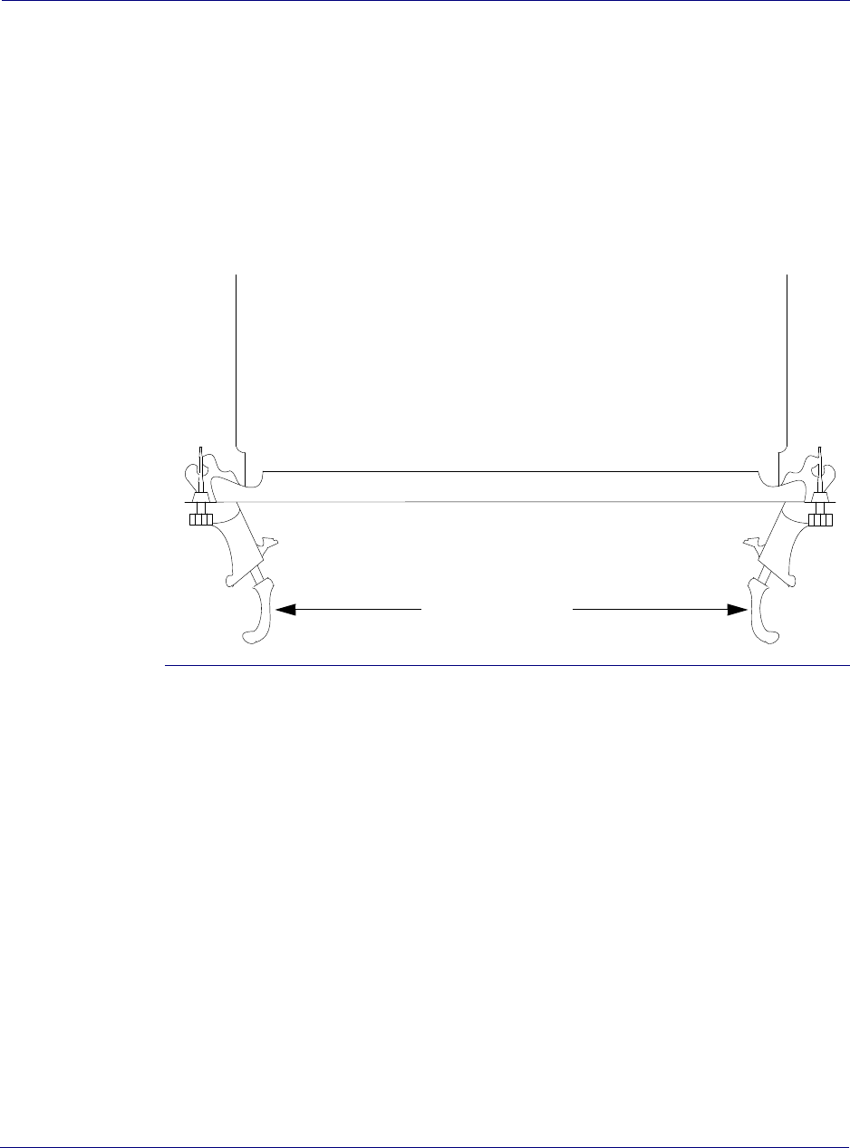
3. Insert the radio module in the bottom slot of the RN chassis and push in until the
connector engages the backplane and the locking latches (see Figure 3-5) on the left and
right close securely.
4. Use a phillips head screwdriver to engage and tighten the captive screws on the left and
right to hold the radio module in place.
Figure 3-5. Module latch detail
Installing the ADCC module
Airvana packs the ADCC module in a cardboard container measuring approximately 16 in.
(40.6 cm) square, and 3 in. (7.6 cm) deep and weighs approximately 5.6 lbs. (2.5 kg)
Install one ADCC module in the top chassis slot.
Procedure
1. Use a box cutter to carefully open the ADCC module box.
2. Remove the ADCC module from its protective electrostatic bag and verify that the pins
located on the rear of the module are straight and have not been damaged in shipping.
3. Insert the ADCC module in the top slot of the RN chassis and push in until the connector
engages the backplane and the locking latches on the left and right close securely.
4. Use a phillips head screwdriver to engage and tighten the captive screws on the left and
right to hold the ADCC module in place.
Locking latches
Module top view
Chapter 3 lipBTS C30 installation
Connecting to the backhaul network
Airvana ipBTS C30 Installation and Commissioning, Release 4.0 3-7
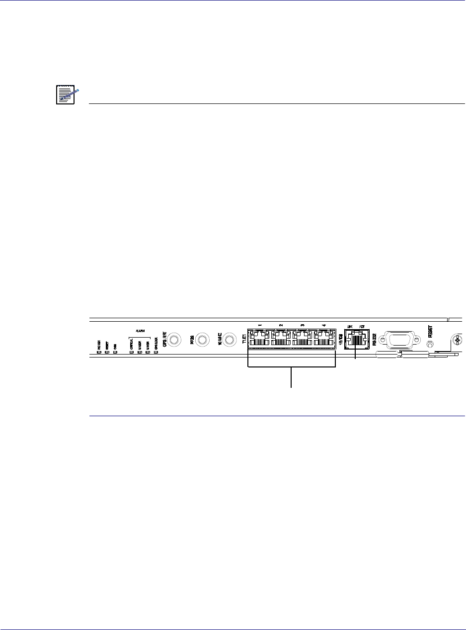
Connecting to the backhaul network
3The ADCC module supports one 100BaseT backhaul interface for a three sector
configuration.
See RN Specifications on page A-1 for the specifications of each connector.
NOTE
Backhaul network cables are not provided. Use standard 100BaseT Ethernet cables to make
the backhaul network connections.
Connecting backhaul cables
Connect to the 100BaseT backhaul network by cabling to the 100BaseT connection on the
ADCC module.
Connecting to the backhaul network through an aggregation router
Use a 100BaseT Ethernet cable to connect one end to the 100BaseT port on the ADCC module
and the other end to the RJ-45 port on the router (see Figure 3-6).
Figure 3-6. Connecting to a backhaul network through a router
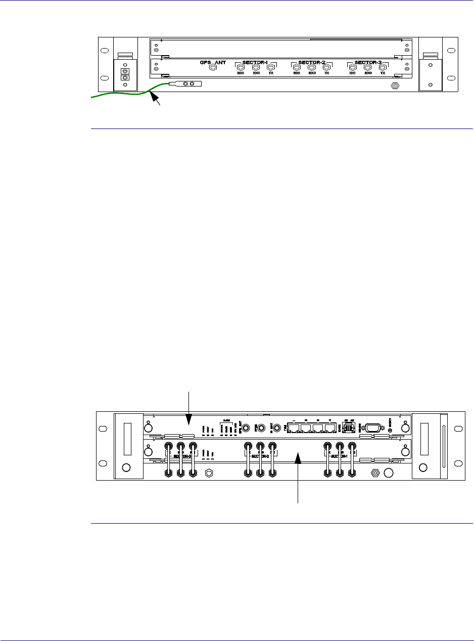
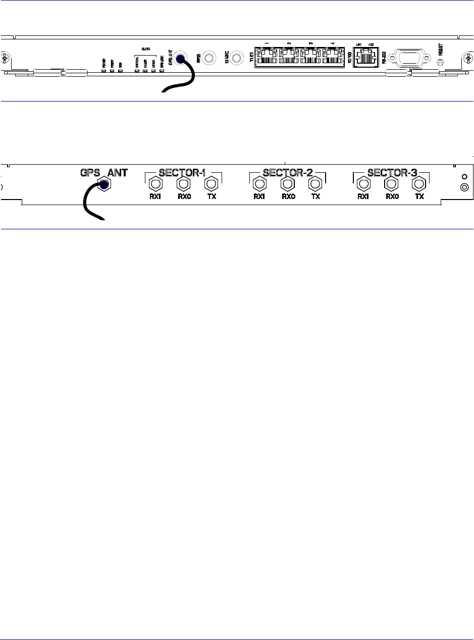
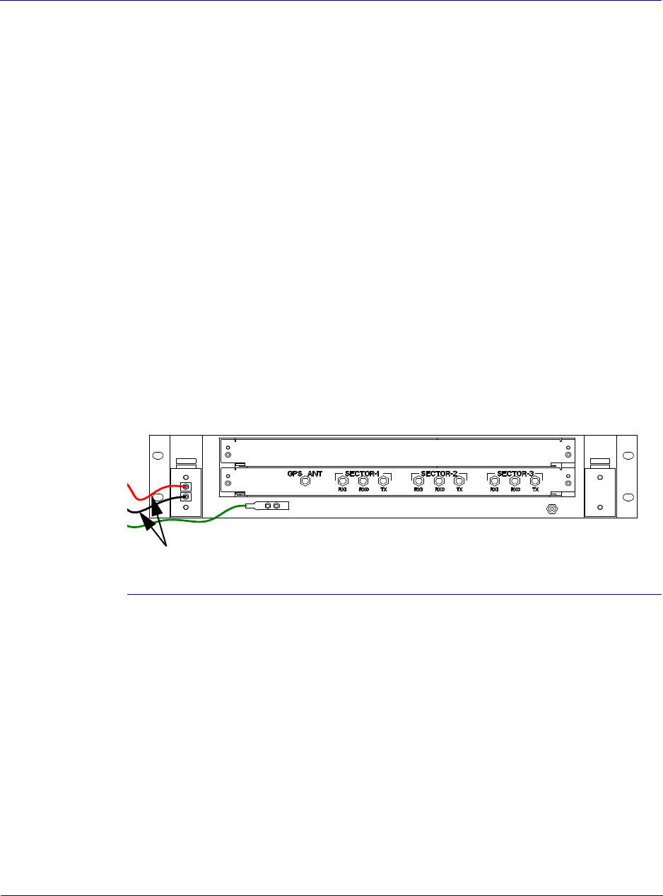
Connecting GPS antenna cables
Connect the GPS coaxial cable SMA connectors.
Procedure
1. Locate the GPS antenna jumper cable and connect one end to the port labelled GPS
Antenna on the ADCC module.
2. Connect the other end of the jumper cable to the SMA port on the chassis directly below
the ADCC LED indicators (see Figure 3-7).
3. Use the torque wrench to tighten the SMA connectors securely to between 5 and 9 inch-
pounds.aking RX connections for sector 2Making RX connections for sector 3.
T1/E1 connectors
100BaseT
ADCC module
(Not used in this release)
Chapter 3 lipBTS C30 installation
Connecting to a power source
3-8 910136 Rev01.00 Standard July 2007
Figure 3-7. GPS connection - front of chassis
Figure 3-8. GPS connection - rear of chassis
Connecting radio module sector ports
The radio module has three SMA connectors per sector on the front and rear of the module.
Below the radio module there are matching SMA connectors in the chassis that are pre-wired
at the factory. This procedure connects the nine short jumper cables to the SMA connectors on
the front and rear of the chassis.
Procedure
1. Connect one end of a jumper cable to an SMA port on the radio module.
2. Connect the other end of the jumper cable to the SMA port on the chassis directly below
the first connection.
3. Repeat step 1 and step 2 for the remaining eight SMA connectors.
4. Use the torque wrench to tighten each SMA connector to 1 N-m (9 in-lbs).
Connecting to a power source
Before connecting the ipBTS to the -48V power source follow the instructions in this section to
verify that all pre-power up steps have been completed.
Pre-power on checklist
Before connecting and applying power to the ipBTS verify that the following tasks have been
completed:
ADCC front
Chassis rear
Chapter 3 lipBTS C30 installation
Powering on the RN
Airvana ipBTS C30 Installation and Commissioning, Release 4.0 3-9
• Connect chassis to ground
• Connect all cables and tighten to specifications.
• Connect to power source.
Powering on the RN
The shelf is prewired to distribute power to the installed components like the ADCC, Radio
module and fan tray. The equipment rack containing the ipBTS C30 shelf must have a suitable
power supply and circuit breakers.
Connecting to the power source and powering on the ipBTS
Follow these steps to connect power to the ipBTS C30 RN and to power on the modules.
Procedure
1. Verify that the circuit breaker supplying power to the ipBTS shelf is in the OFF position.
2. Connect to your -48VDC power source at the rear of the shelf as shown in Figure 3-9
Figure 3-9. Connecting to a power source
3. After you connect the ground and power feeds and have tested the connections set the
circuit breaker to ON to power up the components of the ipBTS.
4. Monitor the ADCC and Radio module LED indicators to verify that the module is
operating normally. See the following sections, ADCC LED indicators and Radio module
LED indicators for more information.
This completes the ipBTS installation process. Go to RN commissioning on page 4-1 to
connect the RN to the CDMA network.
Verifying module status
As the ipBTS powers up look at the LED lights on the front of each module to verify that the
system powers up normally.
Input A
15 AMP
Input B
15 AMP
To power source

Chapter 3 lipBTS C30 installation
Powering on the RN
3-10 910136 Rev01.00 Standard July 2007
ADCC LED indicators
There are seven indicator LEDs on the front of the ADCC module. The LEDs provide the
following status information:
• POWER - On (green) indicates bulk power is available to the module.
• RESET - On (green) indicates the module is in a reset state.
• OOS - On (red) indicates the module is Out Of Service due to fault or not ready.
• CRITICAL - Summary alarm: Critical
• MAJOR - Summary alarm: Major
• MINOR - Summary alarm: Minor
• GPS LOCK - On (green) indicates the GPS receiver is in a locked state.
10/100 Ethernet backhaul
Two LED indicators on the RJ45 connector provide the following information:
• LNK - On (green) indicates that Link is established.
• ACT - On (green) indicates transmit and receive activity.
Radio module LED indicators
There are three indicator LEDs on the front of each radio module. The LEDs provide the
following status information:
• POWER - On (green) indicates bulk power is available to the module.
• RESET - On (green) indicates the module is in a reset state.
• OOS - On (red) indicates the module is Out Of Service due to fault or not ready.

Airvana ipBTS C30 Installation and Commissioning, Release 4.0 4-1
Chapter 4
RN commissioning
This chapter explains the steps required to commission the ipBTS C30. Specifically, it contains
the following sections:
•Requirements on page 4-1
•CLI connection on page 4-3
•Establishing a console connection on page 4-4
•Connecting the laptop to the ipBTS C30 on page 4-7
•Downloading and activating new software on page 4-8
•Downloading and activating new software on page 4-8
•Verifying SNTP time on page 4-11
•Commissioning the ipBTS C30 on page 4-11
•Performing Loopback tests on page 4-12
•Configuring IP on the Ethernet port and laptop on page 4-20
•Establishing the CLI/SSH/Ethernet connection on page 4-21
•Updating node software on page 4-23
Requirements
The ipBTS C30 must be completely installed and powered up. Follow the procedures in
Chapter 3, ipBTS C30 installation before proceeding with the steps in this chapter.
Hardware requirements
Commissioning requires the following hardware:
• Laptop running Microsoft Windows 2000 or Windows XP.
• An Ethernet network interface card (NIC) on the laptop.
The software is transferred to the ipBTS C30 over the Ethernet.
• A cross-over ethernet cable with standard RJ-45 connectors.

Chapter 4 lRN commissioning
Requirements
4-2 910136 Rev01.00 Standard July 2007
• The cross over cable is required to connect the laptop Ethernet port directly to the ADCC
Ethernet port without going through an Ethernet switch. If you bring an Ethernet switch,
then two straight-through Ethernet cables are also required (laptop to switch, and switch to
ADCC).
• Serial cable with male DB-9 connector for attaching to the female DB-9 on the ADCC
side and a connector on the laptop side that is correct or the laptop’s serial port.
• For information on the DB-9 pin-out, see Appendix A.
• Power meter with a power sensor to test and set RF transmission power during
commissioning with connector/adapter appropriate for the antenna cables exiting the Rox
System rack seal.
• 30 dB attenuator pad with connector appropriate for antenna jumper cable rated for a
maximum of 50 watts.
• A power splitter to split the transmit signal for use by the power meter and the AT, with
appropriate cables and connector adapters.
• A 13/16 inch open ended wrench.
• A torque wrench with 13/16 inch open ended bit.
• A 5/32 slotted screw driver.
• A thread tapping kit with 1/4-20 thread bit at 3/4 inch depth.
• 1xEV-DO access terminal (AT) for testing purposes.
Software requirements
Commissioning requires the following software:
• Commissioning script created by network planning personnel.
The commissioning script comprehensively configures the ipBTS C30 for normal
operations.
The following software and hardware is also required if the field technician needs to change
the software release running on the ipBTS C30:
• SFTP client software to transfer the software release to the ipBTS C30. You can choose to
use one of the open-source clients like WinSCP, PuTTY, or PSFTP, or any other third
party application that supports these protocols. An SFTP connection is similar to a
standard FTP connection but uses a secure communications tunnel. On a Windows
computer connected to the network that includes the ipBTS C30, open a command prompt
session. Examples in this guide use the PSFTP client. Type PSFTP IP.ADDRESS to open
the connection.
The ADCC software has an SFTP server that is used to transfer the release to the ipBTS
system.
• Terminal emulation software, such as HyperTerminal installed on the laptop.
• The technician must configure the IP address of the laptop Ethernet NIC.
IP must be configured on the laptop Ethernet NIC and on the ADCC Ethernet port in order
to use SFTP to transfer the software release from the laptop to the ADCC.
Chapter 4 lRN commissioning
CLI connection
Airvana ipBTS C30 Installation and Commissioning, Release 4.0 4-3
• The new software release.
CLI connection
The command line interface (CLI) enables text-based, command-oriented management of the
ipBTS. You can access the CLI in three ways:
Connecting to the serial port
This is a direct connection to the serial port on the ADCC control card. This is the simplest
form of CLI connection. It is only available when you are local to the serial port. This form of
CLI connection is required during initial phases of commissioning. For example, you must use
a CLI serial connection to set the Ethernet IP address if you then want to SSH using the
Ethernet ports.
The CLI/serial connection is made by connecting a laptop running terminal emulation software
to the serial port on the ADCC module.
You can only have a single serial connection to a ipBTS C30 when using a serial port. The
serial connection requires a cable to link the serial port on the network element to a serial port
(typically a COM port) on a laptop or other device. Launch a terminal emulation program on
the laptop (such as HyperTerminal) and configure the communications settings appropriately.
SSH using Ethernet port
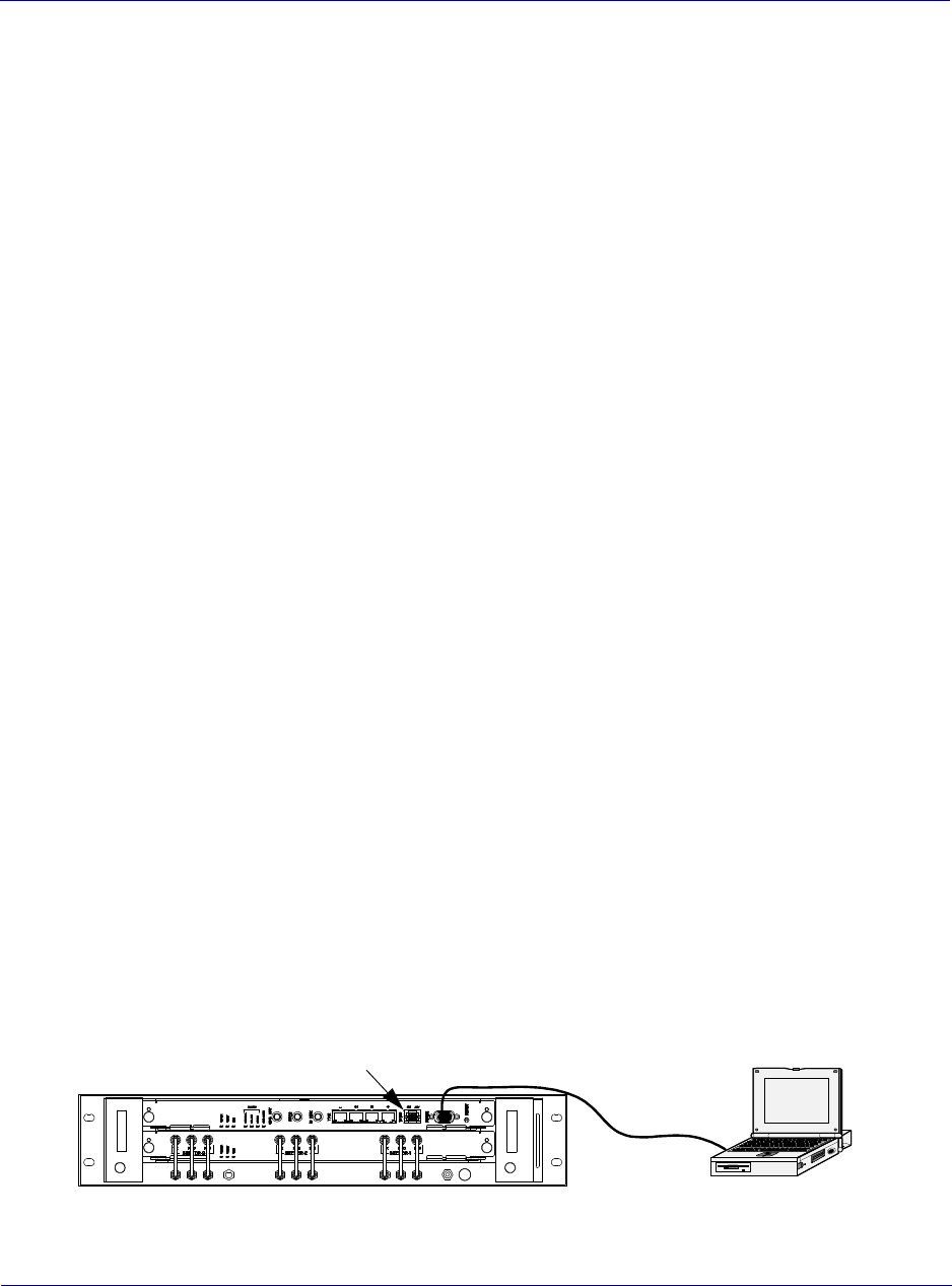
This connection mode uses a laptop’s Ethernet adapter to connect to the Ethernet port on the
ADCC module. Configure the IP address on the laptop attached to the Ethernet port, and
establish an SSH session for CLI access.
Make the CLI/SSH/ Ethernet connection by connecting an Ethernet adapter on your laptop to
the Ethernet port on the ADCC module, directly using a straight through cable. You must
configure appropriate IP addresses and masks on the ADCC Ethernet port (using the serial
port) and on the laptop Ethernet port. Establish an SSH session and open a CLI session with
the ipBTS C30 using the node IP address or the Ethernet IP address.
Because you can open multiple CLI sessions at a time using SSH, this method is required
during certain phases of the commissioning procedure.
Straight through
serial cable
ipBTS RN ADCC Ethernet port

Chapter 4 lRN commissioning
Establishing a console connection
4-4 910136 Rev01.00 Standard July 2007
Figure 4-1. Ethernet connection
Establishing a console connection
This procedure explains how to connect the laptop’s COM port to the active ADCC serial port
and how to start the CLI/serial session. The ipBTS C30 must be powered on.
Requirements
This procedure requires the hardware and software shown in the table below.
Table 4-1. Required hardware
Component Function
Laptop or PC running
Windows 2000 or XP,
with a serial port and
an Ethernet port
Provides a physical connection to the ipBTS C30.
Note: The Ethernet port is necessary only if you are downloading software using an Ethernet
connection, which is recommended.
RS-232 serial port
cable, with a 9-pin DE
female connector
The RS-232 serial port cable (female to female, straight through cable) is a standard cable required to
connect the laptop’s serial port to the ipBTS C30’s serial port.
Ethernet Loopback
connector
Allows you to perform Loopback tests on the Ethernet port. The wiring assignments for an Ethernet
Loopback connector are shown below.
Note: The Ethernet Loopback connector is necessary only if you are testing the Ethernet port.
Pin From Description Pin
To
Description
1 Transmit, positive 3 Receive, positive
2 Transmit, negative 6 Receive, negative
Ethernet (RJ-45) cross-
over cable
Connect your laptop’s Ethernet port to the ipBTS C30’s Ethernet port.
Note: The Ethernet cross-over cable is necessary only if you are downloading software using an
Ethernet connection, which is recommended.

Chapter 4 lRN commissioning
Establishing a console connection
Airvana ipBTS C30 Installation and Commissioning, Release 4.0 4-5
Configuration parameters
This section describes the configuration information you must have to commission the
ipBTS C30. To commission the ipBTS C30, you must know the following:
• ipBTS C30’s node IP address
• ipBTS C30’s Ethernet port IP address
• Laptop’s Ethernet port IP address
Table 4-2. Required software
Component Function
Terminal emulation program, such as
HyperTerminal which comes standard
with Microsoft Windows
The terminal emulation program allows you to download and
upload software, as well as access the CLI (command line
interface).
An open-source client like WinSCP,
PuTTY, or PSFTP, or any other third
party application that supports these
protocols.
Required to connect to modules using SFTP and SSH
protocols.
Version of software that should be on
the ipBTS C30
Enables you to determine if the version of software currently
on the ipBTS C30 needs to be upgraded.
Note: For more information, contact your network planner.
Commissioning script Configures the ipBTS C30 with necessary attributes to
commission the device.
Note: The configuration script is necessary only if you are
using a script to commission the device. In this guide, the
Commissioning script is referred to as <script_filename>.
For more information about the Commissioning script,
contact your network planner.
ipBTS C30 software release Enables you to download the most recent version of software
to the ipBTS C30.
Note: The software release is necessary only if you need to
upgrade the version of software currently on the ipBTS C30.
In this guide, the software release image file is referred to as
<software_image >.tar. For more information about the
software image, contact your network planner.

Chapter 4 lRN commissioning
Establishing a console connection
4-6 910136 Rev01.00 Standard July 2007
NOTE
The Ethernet port IP addresses are necessary only if you are downloading software using an
Ethernet connection, which is recommended. For more information, contact your network
planner.
Table 4-3. Configuration parameters
Object Parameter Description
Interfaces ifAdminStatus The desired state of the interface: up (1), down (2), or testing (3).
Note: The testing (3) state indicates that no operational packets can be passed.
The address at the protocol layer immediately “below” the network layer in the
protocol stack.
Note: For interfaces that do not have such an address, for example, a serial
connection, the ifPhysAddress has a length of zero (0).
ifPhysAddress
SectorElements TimingAdvance The timing advance for the SectorElement. Range {0..255} with default 0.
ControlChannelRate The data rate of the Control Channel of the SectorElement. Range: unknown (1),
38.4 Kbps (5), 76.8 Kbps (6) with default value unknown (1).
PNOffset The pn offset for the SectorElement. Range: {0..511} with a default (0).
CountryCode The country code with which the SectorElement is associated. Range: {0..255}
with a default (0).
SubnetMaskLength The length of the subnet mask used to extract the subnet from the sector ID.
Range: {0..127} with a default (0).
RouteUpdateRadius The distance measured between the serving sector and the sector that triggered a
new route update. Range: {0..2047} with a default (0).
SectorIndex The sector index number of the sector. Range {1..65535}.
CarrierIndex The index of the carrier object to which this SectorElement is bound. Range:
{1..65535}
Note: The value of this attribute can be changed only when the status of this
SectorElement object is down (1).
AdminStatus The administrative status for the SectorElement. Range: down (1), up (2),upTest
(3)

Chapter 4 lRN commissioning
Connecting the laptop to the ipBTS C30
Airvana ipBTS C30 Installation and Commissioning, Release 4.0 4-7
Connecting the laptop to the ipBTS C30
Follow this procedure to establish a serial connection between your laptop and the ipBTS C30.
1. Verify the ipBTS C30 is powered on. (See Table 3 on page 1-8.)
• If the ipBTS C30 is powered on, continue with step 2.
2. Connect one end of the RS-232 serial cable to your laptop’s serial port and the other end to
the ipBTS C30’s serial port.
3. Power on your laptop..
Sectors sectorIndex The index of the sector to which this SectorElement is bound. Range: {1..65535}.
Note: The SectorIndex can be changed only when the status of this
SectorElement object is down (1).
sector Latitude North The geographic latitude of the center of the antenna array serving the sector.
Range: {-90,000 to 90,000} 1/1000 of a degree North and South of Equator.
When configuring this attribute from the EMS, a negative value denotes South
and positive denotes North. When configuring from the CLI, specify North or
South. Default (0).
sector Longitude East The longitude of the center of the antenna array serving this sector. {-180,000 to
180,000} 1/1000 of a degree East and West of the Prime Meridian.When
configuring this attribute from the EMS, a negative value denotes West and
positive denotes East. When configuring from the CLI, specify East or West.
Default (0).
Carriers ChannelNumber The channel number within the BandClass on which the carrier is to operate. The
default value is (2047).
CellRadius The size of the cell corresponding to the SectorElement, specified in chips.
Range: {0...512} with the default value (0).
AccessCycleDuration The access cycle duration, measured in slots. Values: (8, 16, 32, 64, 128) with the
default value (64).
Modem Mode The mode of the modem. Range: unknown (1), other (2), oneCarrierOneSector
(3), oneCarrierThreeSector (4), twoCarrierBiSectorOmni (5).
ipBTS C30 OperStatus The operational status of the ipBTS C30. Range: unknown (1), other (2), down
(3), up (4), test (5), fault (6).
AdminStatus The administrative status. Range: down (1), up (2), test (3).
LastChangeTime The last time the operational status changed.
RNC Priority The priority of the RNC. Range: {0..1000} with the default (0).
Table 4-3. Configuration parameters (continued)
Object Parameter Description

Chapter 4 lRN commissioning
Downloading and activating new software
4-8 910136 Rev01.00 Standard July 2007
Downloading and activating new software
This section describes how to download software from your laptop to the ipBTS C30 using a
serial connection and an Ethernet connection. Specifically, it contains the following sections:
•Establishing a serial connection on page 4-8
•Establishing an Ethernet connection on page 4-10
NOTE
Downloading software over an Ethernet port is faster than downloading over a serial port.
Therefore, Airvana recommends you have an Ethernet connection when downloading
software.
Establishing a serial connection
This section describes how to download the new image file from your laptop to the
ipBTS C30, as well as how to activate the new image file using a serial connection.
Specifically, it contains the following sections:
•Downloading the new image file on page 4-8
•Expanding and activating the new image file on page 4-9
NOTE
If you are using a serial connection and cancel the download task at any time, you must
enter <Ctrl C> on the console three (3) times. Otherwise, the command line interface
(CLI) is in a frozen state.
Downloading the new image file
Follow this procedure to download the <software_image>.tar file from your laptop to the
ipBTS C30.
1. Start the HyperTerminal client.
The HyperTerminal window shown below displays.

Chapter 4 lRN commissioning
Downloading and activating new software
Airvana ipBTS C30 Installation and Commissioning, Release 4.0 4-9
Figure 4-2. HyperTerminal window screen
2. Click the Call icon on the toolbar.
3. Click the Call using pulldown menu and select TCP/IP (Winsock) as the connection
method.
4. Log in with the Username and Password.
The ipBts-XXX> prompt displays.
5. At the ipBts-XXX> prompt, enter the following commands to transfer the new image
file to the ipBTS C30:
ipBts-XXX>shell
ipBts-XXX(shell)(disk0:/)>cd images
6. SFTP the new image file.
7. From the ipBts-XXX(shell)(disk0:images)> prompt, enter the following
commands:
ipBts-XXX(shell)(disk0:images)>cd ..
ipBts-XXX(shell)(disk0:)>exit
ipBts-XXX>
8. Close the HyperTerminal window.
A message displays confirming you want to disconnect.
9. Click Ye s to disconnect or No to not disconnect.
Expanding and activating the new image file
Follow this procedure to expand and activate <software_image>.tar. This procedure assumes
you have an active CLI/serial connection to the ADCC module.
1. Enter the following commands to enter Global Commissioning Mode in the CLI:

Chapter 4 lRN commissioning
Downloading and activating new software
4-10 910136 Rev01.00 Standard July 2007
ipBts-XXX>enable
ipBts-XXX#
2. Enter the following command to reset the node using the software release you just
transferred to the node:
ipBts-XXX#activate image <release>
Where <release> is the filename of the release that was transferred to the node.
For example:
ipBts-XXX#activate image rn.4.0.0.tar
This command:
• Extracts the rn.4.0.0.0.tar release into the disk0:/active directory
• Reboots the node using the 4.0.0.0 release
This step takes about four minutes to complete.
Establishing an Ethernet connection
This section describes how to transfer the new image file from your laptop to the ipBTS C30,
as well as how to activate the new image file using an Ethernet connection. Specifically, it
contains the following sections:
•Establishing an Ethernet connection between your laptop and the ipBTS C30 on page 4-10
Establishing an Ethernet connection between your laptop and the
ipBTS C30
Follow this procedure to establish an Ethernet connection between your laptop and the
ipBTS C30.
1. Verify you have a valid serial connection.
2. Connect one end of the Ethernet cross-over cable into your laptop’s Ethernet port and the
other end of the Ethernet cross-over cable into the ipBTS C30’s Ethernet port.
3. Configure your laptop’s Ethernet port IP address/mask and the ipBTS C30’s Ethernet port
IP address/mask.
NOTE: The laptop’s Ethernet port IP address/mask and the ipBTS C30’s Ethernet port IP
address/mask must be on the same subnet. For example, if the ipBTS C30’s Ethernet port
IP address is 10.10.32.101 and mask is 255.255.255.0, then the laptop’s Ethernet port IP
address should be 10.10.32.102 and mask should be 255.255.255.0.
• You configure your laptop’s Ethernet port IP address using the Control Panel.
For additional information about configuring the laptop’s Ethernet port’s IP address,
contact your system administrator.
• You configure the ipBTS C30’s Ethernet port IP address using the CLI.

Chapter 4 lRN commissioning
Verifying SNTP time
Airvana ipBTS C30 Installation and Commissioning, Release 4.0 4-11
Verifying SNTP time
Follow this procedure to verify the ipBTS C30 is receiving the correct timing information from
the BTS.
1. From the CLI console, enter ipBts-XXX> show sntp time to display the current
UTC time and output similar to this:
Sntp Time Details - UTC
Timing Source = 10.10.50.4
Base Secs = 3219347575 (bfe35877)
Base Nsecs = 820540580 (30e874a4)
Base TBH = 11 (0000000b)
Base TBL = 3003409790 (b304657e)
Current Secs = 3219347773 (bfe3593d)
Current Nsecs = 863521250 (337849e2)
Num Leap Secs (since 1980) = 13
Date = 2007:1:6
Time = 23:16:13.863
2. Verify that the date and time are correct.
Commissioning the ipBTS C30
This section describes how to configure the ipBTS C30 using the Commissioning script.
Specifically, it contains the following section:
•Using the Commissioning script on page 4-11
Using the Commissioning script
Follow this procedure to configure the ipBTS C30 using the Commissioning script.
For more information about the Commissioning script, contact your network planner.
1. Download the Commissioning script from your laptop to the ipBTS C30’s disk0:/
config directory.
2. From the tool-bar, select the CLI button.
3. Press <Enter>.
The ipBts-XXX> prompt displays and indicates you are in EXEC Mode.
4. Enter the following commands to enter Privileged EXEC Mode and run the
Commissioning script (<script_filename>).
ipBts-XXX> enable
ipBts-XXX# copy disk0:/config/<script_filename>
system:running-config

Chapter 4 lRN commissioning
Performing Loopback tests
4-12 910136 Rev01.00 Standard July 2007
•copy is the CLI copy command
•disk0:/config/<script_filename> specifies the source file to copy (in
this case, the Commissioning script file name including the full path to the
commissioning script)
In the above example, the Commissioning script is located on disk 0 in the config
directory.
•system:running-config is the destination file
You always specify system:running-config as the destination file when using
the CLI copy command to run the commissioning script.
The ipBTS C30 runs the Commissioning script. When the script finished executing, the
following message displays:
ipBts-XXX# script done
If the script fails to execute successfully or encounters errors, the CLI displays the
appropriate error message.
5. Enter the following commands to return to EXEC Mode:
ipBts-XXX# exit
ipBts-XXX>
6. Close the CLI console.
Performing Loopback tests
This section describes how to run Loopback tests on the Ethernet port. Specifically, it contains
the following sections:
•The loopback test process on page 4-12
•Backhaul loopback testing on page 4-13
•Ethernet loopbacks on page 4-14
•Looping back Ethernet backhaul links on page 4-14
•Looping back at the Ethernet port on page 4-15
•Entering diagnostic mode and configuring test parameters on page 4-15
•Performing external loopback tests on backhaul links on page 4-16
•Troubleshooting failed backhaul links on page 4-17
•Removing physical loopbacks on page 4-19
The loopback test process
This is the process you should follow for performing loop back tests. Be sure to read and
understand this material before continuing.

Chapter 4 lRN commissioning
Performing Loopback tests
Airvana ipBTS C30 Installation and Commissioning, Release 4.0 4-13
1. Understanding the backhaul loopback process.
2. Install external loopbacks on each backhaul cable.
This section describes how to create and install loopback connectors on each backhaul
cable.
• For information about looping back Ethernet backhaul link(s), see Looping back
Ethernet backhaul links on page 4-14
• For information about looping back at the Ethernet port, see Looping back at the
Ethernet port on page 4-15
3. Preparing for loopback tests.
This section describes how to enter CLI diagnostic mode and configure the test
parameters.
For more information, see Entering diagnostic mode and configuring test parameters on
page 4-15.
4. Running loopback tests on each backhaul.
This section describes how to perform the loopback test for all backhaul links.
For more information, see Performing external loopback tests on backhaul links on
page 4-16.
5. Troubleshooting failed backhaul link(s).
This section describes how to take additional steps to troubleshoot and correct any
backhaul link(s) that failed the external loopback tests.
For more information, see Troubleshooting failed backhaul links on page 4-17.
6. Removing physical loopbacks.
This section explains the external loops at the far end of all cables must be removed once
the Loopback testing is complete.
For more information, see Removing physical loopbacks on page 4-19
Once you have reviewed and understand the Loopback test process, continue with Backhaul
loopback testing.
Backhaul loopback testing
Loopback testing each backhaul link is a critical step that must be completed before the
technician leaves the site. These tests ensure the node is functional, the backhaul link(s) are
properly wired into the backhaul and (optionally) that the backhaul cables and any external
equipment to which they attach (up to the loop back point) are operational.
NOTE
This testing does not include backhaul circuits, only physical layer functionality at the cell
site. Backhaul circuits must undergo end-to-end testing and acceptance at the time they are
brought up by the service provider.

Chapter 4 lRN commissioning
Performing Loopback tests
4-14 910136 Rev01.00 Standard July 2007
The extent of the loopback test (the amount of equipment and cabling that is tested) depends on
where the physical loop back is installed. The farther away from the ipBTS C30 the loopback
is installed, the greater the extent of the test, although Ethernet loopbacks cannot be installed at
the far side of a router, switch, FRAD, or other edge device.
NOTE
If a loopback is installed directly on the backhaul, a bare minimum is tested. For example,
the backhaul cable exiting the ipBTS C30 is not tested.
Airvana recommends installing the loopback at least as far as the far end of each backhaul
cable exiting the ipBTS C30. Installation at that point includes the backhaul cable’s wiring into
the Ethernet port and the backhaul cable itself.
Maximum cable lengths must be considered when installing loopbacks. Loopbacks double the
length of a cable (the cable length now equals the outgoing leg plus the return leg, or twice the
physical cable length). Failure to consider this factor can result in failed loopback tests for
cables that are flawless.
The technician must have appropriate equipment and materials for installing and performing
loopbacks.
Ethernet loopbacks
The Ethernet loopback test has two parts:
• Physically loopback the Ethernet
• Run the loopback test
The loopback can be done externally on the cable or on the Ethernet port by physically
connecting the receive wires (RXs) to the transmit wires (TXs). The loopback can also be done
internally on the hardware transceiver chip. Looping back internally on the transceiver chip
only tests limited hardware functionality and does not test the cable connection or the Ethernet
port. Looping back externally tests more. The Ethernet loopback test is not a standard function
of Ethernet, but is a value-added proprietary feature.
Looping back Ethernet backhaul links
This section explains how to install the physical loopbacks when Ethernet backhaul links are
used. Install the loopback as far as possible along the length of the Ethernet. This increases the
extent of the test. You cannot loopback the Ethernet at the far side of most network devices,
including switches, routers, and FRADS. However, if the Ethernet backhaul cable is connected
to a patch panel (or another passive, pass-through device), you can install the loopback at the
far side of it and thereby include the patch panel in the test.
Because Airvana does not specify the Ethernet cable/connector types, the details of looping
back the Ethernet cables are site-dependent. Typically, Ethernet backhaul cables installed into
the backhaul punch block have an RJ-45 jack at the far-end. This section provides the pin-out
for the RJ-45 jack.

Chapter 4 lRN commissioning
Performing Loopback tests
Airvana ipBTS C30 Installation and Commissioning, Release 4.0 4-15
Physical loopbacks are created by physically connecting the positive transmit wire to the
positive receive wire and connecting the negative transmit wire to the negative receive wire.
NOTE
Loopbacks must be installed on all Ethernet backhaul cables. There is one Ethernet
backhaul cable on non-redundant systems; there are two on redundant systems.
1. Create the Loopback connector.
• If the Ethernet at the point of the loopback installation has an RJ-45 connector on the
far end, create a loopback connector using the pin-out in Table 4-1 on page 4-4.
• If the Ethernet backhaul(s) have a different connector, create a loopback connector as
appropriate.
2. Install the loopback connector onto the far end of each Ethernet cable.
Looping back at the Ethernet port
To install a physical loopback at the Ethernet port in preparation for running external loopback
tests on Ethernet backhaul links, simply connect the loopback connector to the appropriate
port.
For information about how to create Ethernet loopback connectors, see Table 4-1 on page 4-4.
NOTE
When looping back at the port, the loopback test does not test the cable wired into the port
or the or backhaul cables. This is the least desirable location to install the loopback and
should only be used if the other options are not available.
Entering diagnostic mode and configuring test parameters
This procedure explains how to initiate a hard reset and use the CLI to enter diagnostics mode.
NOTE
To perform Loopback tests, you must have a serial connection to the ipBTS C30.
Follow this procedure to enter diagnostics mode and configure test parameters.
1. Press the <Enter> key on your laptop to ensure the CLI session is active.
The command prompt displays, which indicates the session is active.
2. Enter reboot to reboot the ipBTS C30.
The CLI console displays the ipBTS C30’s booting sequence. There is a three-second
window during which you can select diagnostics mode. Prior to starting the three-second
Chapter 4 lRN commissioning
Performing Loopback tests
4-16 910136 Rev01.00 Standard July 2007
window, the system displays a count that counts down to zero and the following message
displays:
Press the <Esc> key followed by the Space Bar key three times
to Enter Diagnostic Mode
NOTE: If you do not press a key before the three-second window passes, the power on
self-tests run and normal operation initiates.
3. Press the Space Bar key three times during the count down, to display the diagnostics
banner.
The >ipBTS C30_SC> prompt displays, indicating you are currently in diagnostics
mode and you can now perform Loopback tests.
4. Resetting the ipBTS C30 causes a warm reboot. Enter the diagnostics mode during that
countdown as you did in step 3.
Performing external loopback tests on backhaul links
Follow this procedure to perform external loopback tests on backhaul links.
NOTE
The T1/E1 ports are not supported in this release of the ipBTS.
1. Enter the following command to start the loopback test:
>ipBts-XXX_SC>commsend <number of tests> <ports>
Where:
•<number of tests> specifies the number times each port is to be tested. The valid
range is between (0 – 100000).
•<ports> specifies the names of the ports to be tested. See Table 4-4.
For example, the following command would start the loopback test for a system with two
E1 backhaul links: >ipBts-XXX_SC>commsend 10 T1 T2
2. Evaluate the results.
Table 4-4. Backhaul links to be tested
<ports>Indicates the following ports to be tested
T1 The first T1 or E1 backhaul
T2 The second T1 or E1 backhaul
T3 The third T1 or E1 backhaul
T4 The fourth T1 or E1 backhaul
FENET1 The primary Ethernet backhaul

Chapter 4 lRN commissioning
Performing Loopback tests
Airvana ipBTS C30 Installation and Commissioning, Release 4.0 4-17
After the test is complete, the following data table displays for each backhaul tested.
Number of Transmitted Frames : x
Number of Received Frames : x
Number of Error Frames : x
Frames without valid Test ID : x
Frames with invalid Data : x
Frame Error Rate : x
Error Counters
Rx Frame Length Violations ... x
Rx Non-octet alignment ... x
Rx Abort Frames ... x
Rx CRC Errors ... x
•If the Number of Received Frames equals the Number of Transmitted
Frames, proceed to Removing physical loopbacks on page 4-19.
•If the Number of Received Frames does not equal the Number of
Transmitted Frames, or if there are any errors counted, you need to
troubleshoot the backhaul. Continue with Troubleshooting failed backhaul links on
page 4-17.
Troubleshooting failed backhaul links
This procedure explains how to run the internal loopback test on backhaul links that failed the
external loopback test. This section also outlines what to do based on the test results: If the
internal loop back passes, troubleshoot the cables and loopback devices.
NOTE
If the internal loopback fails, the node may be faulty and you should call Airvana’s
Technical Assistance Center.
Follow this procedure to perform basic troubleshooting on failed backhaul links.
1. If the backhaul links are T1 or E1, enter the following CLI command to specify the
backhaul links you want to set to internal loopback mode:
>ipBts-XXX_SC>mmb <port memory locations> 04
Where: <port memory locations> are the backhaul links to place into internal
loopback mode. See Table 4-5.

Chapter 4 lRN commissioning
Performing Loopback tests
4-18 910136 Rev01.00 Standard July 2007
For example, the following command sets the second T1 or E1 backhaul to internal
loopback mode: >ipBts-XXX_SC>mmb f500010a 04
2. If the backhaul links are Ethernet, enter the following CLI command:
>ipBts-XXX_SC>poke874 fenet1 13 803c
3. Run the internal backhaul test on the interface(s) you have set to internal loopback mode
with the following CLI command:
4. Enter the following command to start the loopback test:
>ipBts-XXX_SC>commsend <number of tests> <ports>
Where:
•<number of tests> specifies the number times each port is to be tested. The valid
range is between (0 – 100000).
•<ports> specifies the names of the ports to be tested. See Table 4-6.
For example, the following command would start the loopback test for a system with two
E1 backhaul links: >ipBts-XXX_SC>commsend 10 T1 T2
5. Evaluate the results.
After the test is complete, the following data table displays for each backhaul tested.
Number of Transmitted Frames : x
Table 4-5. Specifying backhaul links for internal loopback mode
<port memory location>Indicates the following ports to be set to
internal loopback mode
f500000a The first T1 or E1 backhaul
f500010a The second T1 or E1 backhaul
f500020a The third T1 or E1 backhaul
f500030a The fourth T1 or E1 backhaul
Table 4-6. Specifying backhaul links to be tested
<ports>Indicates the following ports to be tested
T1 The first T1 or E1 backhaul
T2 The second T1 or E1 backhaul
T3 The third T1 or E1 backhaul
T4 The fourth T1 or E1 backhaul
FENET1 The primary Ethernet backhaul

Chapter 4 lRN commissioning
Performing Loopback tests
Airvana ipBTS C30 Installation and Commissioning, Release 4.0 4-19
Number of Received Frames : x
Number of Error Frames : x
Frames without valid Test ID : x
Frames with invalid Data : x
Frame Error Rate : x
Error Counters
Rx Frame Length Violations ... x
Rx Non-octet alignment ... x
Rx Abort Frames ... x
Rx CRC Errors ... x
•If the Number of Received Frames does not equal the Number of
Transmitted Frames, or if there are any errors counted, the node has a fault and
you need to contact Airvana’s Technical Assistance Center. This is the end of this
procedure.
•If the Number of Received Frames does equal the Number of
Transmitted Frames and there are no errors, you must troubleshoot the
following:
• the backhaul cable
• the physical loopback installed earlier in the loopback testing process
• the backhaul wiring into the punch block
• any external equipment the backhaul cable is attached to, for example the DSX
6. Enter >ipBts-XXX_SC>reset to reset the ipBTS C30 and return to operational
mode.
The ipBts-XXX> prompt displays.
Allow the ipBTS C30 to reboot to completion, skipping the diagnostic mode required for
loopback testing.
Removing physical loopbacks
After Loopback testing is complete, remove all external, physical loopbacks installed earlier to
restore the system to operational mode.
CAUTION
Failure to remove any loopbacks installed earlier results in failed backhaul links.
The Loopback testing process is also complete.
Procedure
1. Place the laptop on a secure surface.

Chapter 4 lRN commissioning
Configuring IP on the Ethernet port and laptop
4-20 910136 Rev01.00 Standard July 2007
2. Boot up the laptop.
3. Retrieve the CLI cable.
4. Check the ACTIVE LED to determine if the ADCC module is active
5. Connect the male DB-9 end of the serial cable to the female DB-9 port on the active
ADCC module.
6. Connect the other end of the serial cable to the COM port of the laptop.
7. Launch the terminal emulation program.
You can use HyperTerminal, which comes with windows, or any terminal emulation
program of your choice.
8. Open a terminal connection as appropriate for the terminal emulation software.
9. Set the terminal connection parameters to those shown in Table 4-7.
NOTE: If you are establishing CLI/serial connection the serial ports on the RM or TFU
modules, you must set the Bits per second to 115200.
10. Press <ENTER> on the laptop.
The CLI command prompt displays as follows:
ipBts-XXX>
Configuring IP on the Ethernet port and laptop
This procedure explains how to configure IP addressing so that you can use SFTP to transfer a
new release from the laptop Ethernet port to the node over the ADCC Ethernet port.
This procedure requires an active CLI/serial connection to the ADCC.
Table 4-7. Terminal settings for CLI/serial connection
Setting Value
Terminal emulation type VT220 or VT100
Bits per second (BAUD) 38400
Data bits 8
Parity None
Stop bits 1
Flow control None

Chapter 4 lRN commissioning
Establishing the CLI/SSH/Ethernet connection
Airvana ipBTS C30 Installation and Commissioning, Release 4.0 4-21
Procedure
1. Enter the following commands to set the IP address on the Ethernet port of the active
ADCC:
ipBts-XXX>enable
ipBts-XXX#configure
ipBts-XXX(config)#interface ethernet1/0/1
ipBts-XXX(config-if)#ip address 10.0.0.1/24
ipBts-XXX(config-if)#no shutdown
ipBts-XXX(config-if)#exit
ipBts-XXX(config)#exit
ipBts-XXX#exit
NOTE: Ethernet1/0/1 identifies the Ethernet interface on the ADCC in slot 1 as follows:
The “1” indicates this node. The “0” indicates slot 0, (a virtual slot). The final “1”
indicates the Ethernet port number. This IP address and mask and the IP address and mask
configured in the next step form a subnet. You can use any two IP addresses that are in the
same subnet.
2. Enter the following IP configuration into the Ethernet network interface card (NIC) on
your laptop:
• IP address: 10.0.0.2
• Subnet mask: 255.255.255.0
• Default gateway: no default gateway is required — leave it blank.
3. Verify the connection information using the show int command:
ipBts-XXX>enable
ipBts-XXX#show int
Name Connection IP Address In Octets Out Octets Admin Oper
----------------------------------------------------------------------
ethernet1/0/1 10.40.192.222/16 169137221 7312611 Up Up
mgmt1/0/1 0.0.0.0/0 0 0 Down Down
node1/0/1 10.6.190.222/32 0 0 Up Up
NOTE: Airvana does not specify the laptop operating system and cannot specify the exact
steps you need to take to configure the IP information for the Ethernet NIC.
This procedure is complete. Go to Establishing the CLI/SSH/Ethernet connection on
page 4-21.
Establishing the CLI/SSH/Ethernet connection
This procedure explains how to physically connect the laptop to the node through the Ethernet

Chapter 4 lRN commissioning
Establishing the CLI/SSH/Ethernet connection
4-22 910136 Rev01.00 Standard July 2007
Requirements
This procedure requires the following hardware:
• A cross-over RJ-45 Ethernet cable or two straight-through Ethernet RJ-45 cables and an
Ethernet switch with a power supply. See Ethernet connection on page 4-4 for a
connection illustration.
Procedure
1. Plug one end of your RJ-45 cable into the Ethernet port on the ADCC module.
The Active LED is lit on the ADCC module.)
2. If you are using a cross-over RJ-45 cable and no Ethernet switch to connect the laptop to
the node:
a. Plug the free end of the cable into the laptop Ethernet.
b. Skip step 3 and go to step 4.
3. If you are using two straight-through cables and an Ethernet switch to connect the laptop
to the node:
a. Connect the free end of the cable into a switch port
b. Connect one end of the second cable into another switch port
c. Connect the free end of the second cable into the laptop Ethernet port
d. Power on the Ethernet switch.
The switch LED for the Ethernet port lights indicating an operational Ethernet link.
4. On the laptop, open an SSH session to the node using the node’s Ethernet IP address (or to
the IP address of another Airvana device, for example the ipRNC 1610 to which this node
is homed), as follows:
5. Use an SSH-enabled client (such as PuTTy shown below) to open an SSH CLI session
from the PC to the ipRNC 1610, as follows:
a. From the PC command line window, open the SSH client:
NOTE: The following example uses a random IP address. You must use the one
configured previously for the active SC module’s auxiliary port.
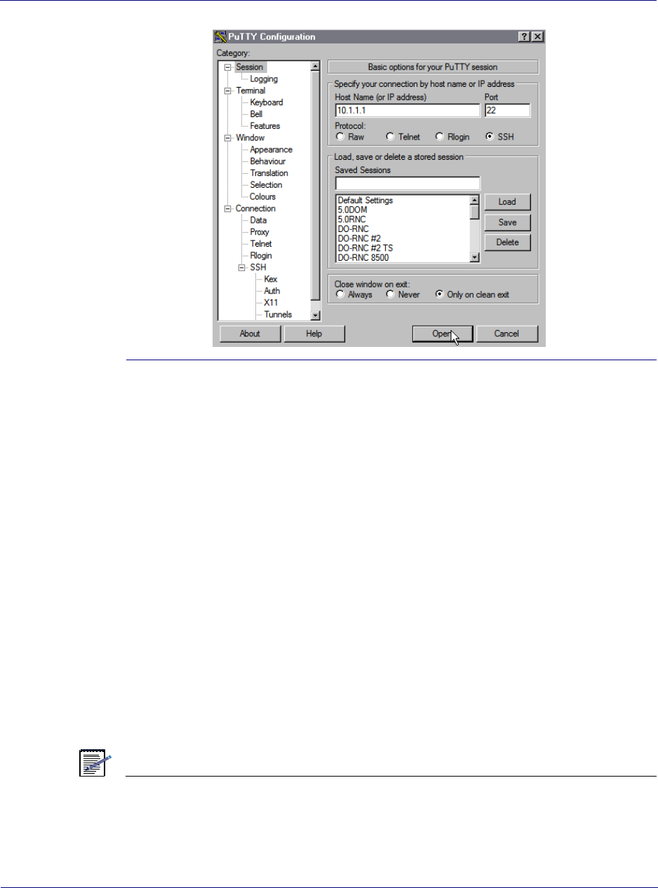
Chapter 4 lRN commissioning
Updating node software
Airvana ipBTS C30 Installation and Commissioning, Release 4.0 4-23
Figure 4-3. Establishing an SSH connection
The following displays indicating a CLI/SSH session is active:
ipBts-XXX>
Updating node software
This section describes how to verify the node’s software version and, if necessary, update the
software.
Verifying the current release and free disk space
The following procedure shows you how to use the CLI to verify the currently active software
release on the node, how to verify the amount of free disk space on the node, and how to
remove files if more free space is needed before transferring a new release to the node. The
procedure assumes that you have an active CLI session.
If there is no need to update the node’s software release the ipBTS commissioning is complete.
NOTE
The node’s software release can be updated later from a centralized network location using
the ipBTS C30 user interface or the CLI through an SSH session.

Chapter 4 lRN commissioning
Updating node software
4-24 910136 Rev01.00 Standard July 2007
Procedure
To verify the current software version and check for free disk space, do the following:
1. Enter the show version command as follows:
ipBts-XXX>show version
The CLI output displays the currently executing release. Make note of whether you need
to update the release.
2. Use the shell command to enter the CLI shell as follows:
ipBts-XXX#shell
The following prompt displays:
ipBts-XXX(shell)(disk0:/)>
3. Enter the ls command to check how much free space there is on the node’s disk as
follows:
ipBts-XXX(shell)(disk0:/)>ls
The following displays with data values as appropriate for the
node. Note the “Free MBytes” at the bottom. This indicates the
amount of free space on the disk.
size date time name
---------- ------ ----- ---------------
32768 May 23 14:43 active/
32768 May 23 14:18 images/
511 May 15 15:23 config.bin
32768 May 23 14:49 logs/
32768 May 20 12:56 backup/
32768 Apr 10 07:52 dcbackup/
524288 May 13 21:18 leofs
Free MBytes 38136
4. If there is less than 30 Mbytes free, use the xrm command as follows to delete all files in
the disk0:/images directory:
ipBts-XXX(shell)(disk0:/)>xrm images
The following displays, indicating the files being deleted from the
c:\images directory.
deleting file images/rn8500.2.0.0.tar
deleting file images/version.txt
...
Re-verify that enough space is available on the disk
5. Enter the exit command to leave the shell and return to the normal CLI prompt.
The following prompt displays:
ipBts-XXX#
This procedure is complete.

Chapter 4 lRN commissioning
Updating node software
Airvana ipBTS C30 Installation and Commissioning, Release 4.0 4-25
Transferring software from the laptop to the node
The following procedure explains how to use SFTP to transfer the new software release from
the laptop to the node over the IP/Ethernet connection. The software release must be on the
laptop.
Requirements
You must establish a CLI/SSH/Ethernet connection from the laptop to the node of the ADCC
Ethernet port.
See Establishing an Ethernet connection between your laptop and the ipBTS C30 on page 4-10
Procedure
To transfer software from the laptop to the node, do the following:
1. On the laptop, open a command line window:
a. Select Start > Run
b. Type cmd in the text box
c. Click the OK button
The command line application window opens and the command prompt displays as
follows:
C:\>
2. Launch the Windows SFTP client in the command line window by entering the following
C:\>psftp 10.0.0.1
The following displays:
Connected to 10.0.0.1:
220 VxWorks (5.4) SFTP server ready
User (<IP ADDRESS):(none)):
3. Press the <ENTER> key.
The following displays:
Password required:
4. Press the <Enter> key.
The following displays:
sftp>
5. Enter the following to enable hash mark printing.
sftp>hash
6. Enter the following to change the FTP directory on the node to the images directory:
sftp>cd images
The following displays:
sftp>Hash mark printing On sftp: (2048 bytes/hash mark).

Chapter 4 lRN commissioning
Updating node software
4-26 910136 Rev01.00 Standard July 2007
NOTE
SFTP outputs a number sign (#) to the DOS SFTP command prompt for every 2048 bytes
transferred. This enables you to watch the progress of the file transfer.
7. Enter the following to change the SFTP file transfer mode to binary:
sftp>binary
You are now ready to transfer the software release from the laptop to the node.
8. Enter the following to transfer the release from the laptop to the node disk0:/images
directory:
sftp>put <path and release filename>
Where <path and release filename> is the complete path and filename for the release on
your laptop.
For example, if the release is in the c:\releases\skyBTSRN\ directory and if the release
filename is rn.4.0.0.tar, enter the following
sftp>put c:\releases\skyBTSRN\rn.4.0.0.tar
SFTP displays a long series of hash marks (“###########...) indicating the file
transfer is progressing.
The following displays to indicate a successful file transfer:
(line #): Transfer completed
The release is now on the node in the following directory: disk0:/images
Go to Activating the new release.
Activating the new release
Follow this procedure to use the activate command to make the transferred software the current
active release. This procedure assumes you have an active CLI/serial connection to the ADCC
module.
1. Enter the following commands to enter Global Commissioning Mode in the CLI:
ipBts-XXX>enable
ipBts-XXX#
2. Enter the following command to reset the node using the software release you just
transferred to the node:
ipBts-XXX#activate image <release>
Where <release> is the filename of the release that was transferred to the node.
For example:
ipBts-XXX#activate image rn.4.0.0.tar
This command:
• Extracts the rn.4.0.0.0.tar release into the disk0:/active directory

Chapter 4 lRN commissioning
Updating node software
Airvana ipBTS C30 Installation and Commissioning, Release 4.0 4-27
• Reboots the node using the 4.0.0.0 release
This step takes about four minutes to complete.
NOTE
If you also need to update the boot code, add the updateboot switch to the command as
follows: activate image <release>.
The ipBTS C30 commissioning process is complete.

Chapter 4 lRN commissioning
Updating node software
4-28 910136 Rev01.00 Standard July 2007

Airvana ipBTS C30 Installation and Commissioning, Release 4.0 5-1
Chapter 5
RN hardware components
This chapter describes the components and shelf-mounted modules that make up the ipBTS
C30 and provides an illustration of each module in the system.
An ipBTS system can be configured to support three sector Radio Kits and requires one shelf
for a three sector system. A shelf is a standard 2U, 19-inch TELCO universal server rack, or
similar cabinet. This chapter contains the following sections:
•RN shelf components on page 5-1
•ADCC module on page 5-1
•Radio module on page 5-2
•Fan trays on page 5-2
•Air filter on page 5-3
RN shelf components
All components in the ipBTS RN shelf are Field Replaceable Units (FRUs). This section
describes the functions of each module.
ADCC module
The ADCC is the 1xEvDO Channel Card in the ipBTS C30 system. One ADCC module
controls three radio sectors and is responsible for the following functions:
• System Controller
• Timing
• 1xEvDO Modem
• Power conditioning and power supply
Chapter 5 lRN hardware components
RN shelf components
5-2 910136 Rev01.00 Standard July 2007
Figure 5-1. ADCC module
Radio module
The Radio Module (Figure 5-2) for three sectors is contained in the ipBTS C30 RN chassis.
The Radio Module main functions are:
• Modulation of the RF signal provided by the ADCC (I/Q baseband signals), amplification
and emission.
• Two-way diversity reception and amplification of the RF signal, demodulation to I/Q
baseband signals and provided to the ADCC.
Figure 5-2. Radio module
Fan trays
The ipBTS contains two redundant cooling fan trays which are part of the RN chassis
assembly. Fay trays are field replaceable. A fan cover (shown in Figure 5-3) protects the front
of the fan tray assembly and can be removed to replace a fan by loosening the captive screws.
See Module locking latch detail on page B-3 for replacement instructions.
Loosen screw to remove tray
Loosen screw to remove tray
Fan tray Fan tray
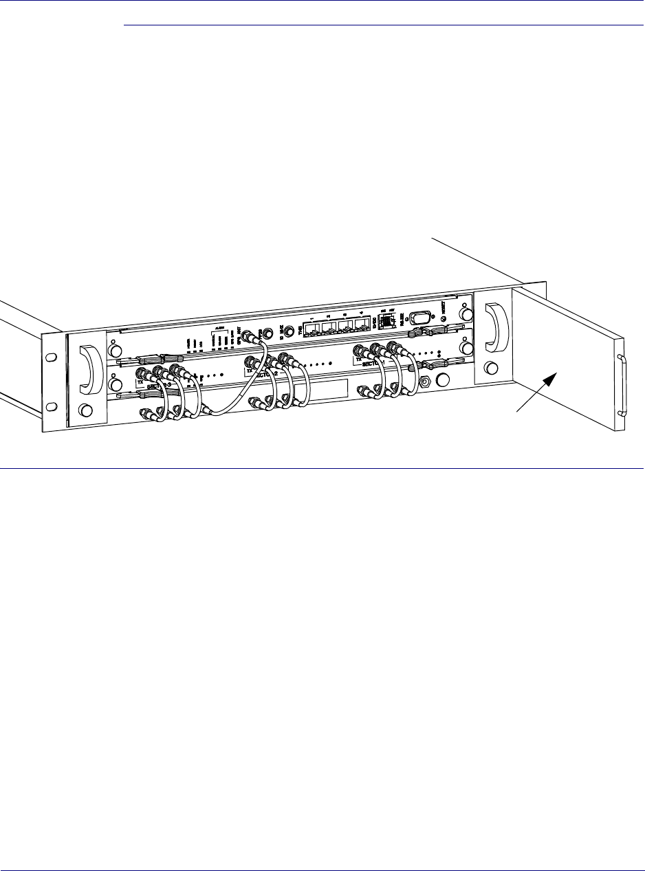
Chapter 5 lRN hardware components
RN shelf components
Airvana ipBTS C30 Installation and Commissioning, Release 4.0 5-3
Figure 5-3. Fan tray locations
Air filter
The chassis contains a replaceable air filter (Figure 5-4) on the right side of the shelf. The air
filter, in conjunction with the fan tray modules, continuously clears the air circulating through
the RN shelf of dust and other contaminants that could interfere with the proper operation of
the RN shelf modules.
The air filter should be inspected and, if necessary, replaced at least every six months. See
Replacing the air filter on page B-5 for replacement instructions.
Figure 5-4. Air filter location
Air filter

Chapter 5 lRN hardware components
RN shelf components
5-4 910136 Rev01.00 Standard July 2007
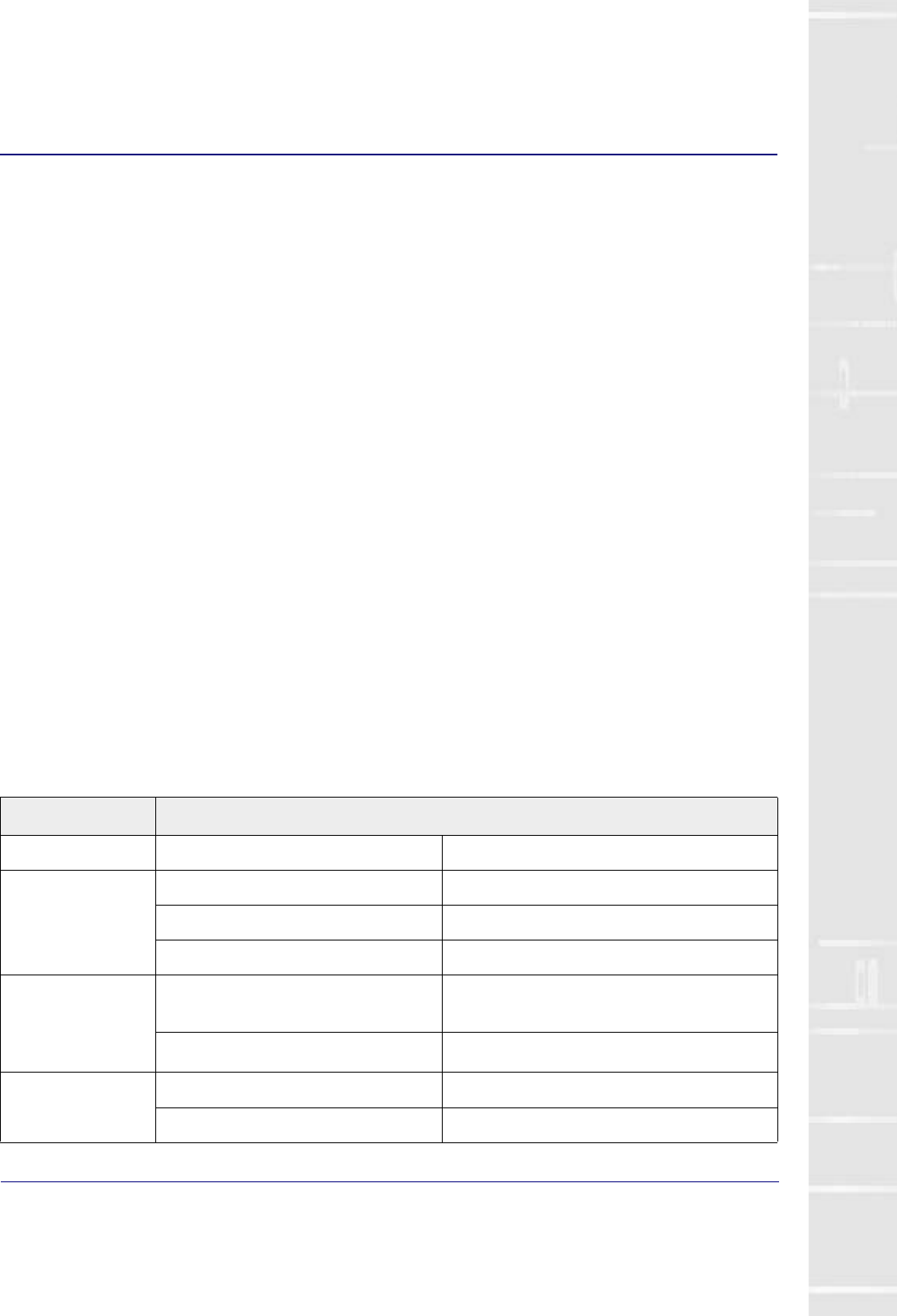
Airvana ipBTS C30 Installation and Commissioning, Release 4.0 A-1
Appendix A
RN Specifications
This appendix provides specifications for the ipBTS. It contains the following sections:
•Physical and environmental specifications on page A-1
•Power specifications on page A-2
•Module specifications on page A-3
•T1/E1 connector pin assignments on page A-3
•100BaseT connector pin assignments on page A-4
•Craft port interface pin assignments on page A-5
Physical and environmental specifications
Table A-1describes the ipBTS physical and environmental requirements.
Table A-1. Physical and environmental specifications
Specification Description
Weight Maximum weight 35 lbs. (15.8 kg)
Dimensions of chassis Height 3.5 in. (8.8 cm)
Width 17.5 in. (44.5 cm)
Depth 18.5 in.s (47 cm)
Operating temperature
range
Normal 5°C to 40°C
Short term -5°C to 50°C
Relative humidity Normal 5% to 85%
Short term 5% to 90%

Appendix A l
Power specifications
A-2 910136 Rev01.00 Standard July 2007
Power specifications
Table A-2 describes the ipBTS power requirements.
Input power interfaces
Table A-3 shows the supported input power connections.
Ratings UL UL 1950 (UL60950), UL94.V-1, UL94.VW-1
Altitude Maximum 6,000 feet (1,800 meters). At altitudes between 6,000
feet (1,829 m) and 12,000 feet (3,658 m), the
specified upper limit for operational temperature
(+40 degrees C) is reduced by 2 degrees C every
1,000 feet.
Table A-1. Physical and environmental specifications (continued)
Specification Description
Table A-2. Power specifications
Specification Description
Nominal DC Input Voltage -48 VDC
DC Input Operating Range -40 VDC to -57 VDC
Typical Input Current at -48 VDC 3A
Maximum Input Current at -48 VDC 5A
Table A-3. Input power interfaces
Terminal Function
-48VDC-A Input Power, -48VDC.
Input Power Feed A
-48RTN-A Input Power, -48VDC Return.
Input Power Feed A
-48VDC-B Input Power, -48VDC.
Input Power Feed B
-48RTN-B Input Power, -48VDC Return.
Input Power Feed B
Appendix Al
Module physical specifications
Airvana ipBTS C30 Installation and Commissioning, Release 4.0 A-3
Module physical specifications
Table A-4 describes individual ipBTS module dimensions and weights.
ADCC connector specifications
Table A-6, Table A-6, and Table A-7 provide the provide the specifications and pin out
assignments for the GPS antenna, RJ-48C and RJ-45 100BaseT connectors located on the front
of the ADCC module.
Table A-4. Module specifications
Module Specifications
ADCC module Weight 5.6 lbs (2.5 kg)
Height 17.5 inches (444.5 mm)
Length 15.0 inches (381 mm)
Depth 1.2 inches (30.48 mm)
RM
(Radio Module)
Weight 5.6 lbs (2.5 kg)
Height 17.5 inches (444.5 mm)
Length 15.0 inches (381 mm)
Depth 3.8 inches (96.52 mm)
Table A-5. GPS antenna specifications
Function Specification
Frequency 1.57542 GHz (L1)
Impedance 50 ohms
Input level -135 dBm and -115 dBm as measured with 50 ohms
DC power supplied to GPS antenna
using the center conduit
+5VDC, +/- 0.1VDC, 25 mA maximum

Appendix A l
ADCC connector specifications
A-4 910136 Rev01.00 Standard July 2007
NOTE
The T1/E1 ports are not supported in this release of the ipBTS.
Table A-6. T1/E1 connector pin assignments
Pin Function I/O
1 RX- (Ring) I
2RX+ (Tip) I
3N/C
4TX- (Ring) 0
5TX+ (Tip) O
6N/C
7N/C
8N/C
Table A-7. 100BaseT connector pin assignments
Pin Function I/O
1TX+ O
2TX- O
3RX+ I
4N/C
5N/C
6RX- I
7N/C
8N/C

Appendix Al
Radio module specifications
Airvana ipBTS C30 Installation and Commissioning, Release 4.0 A-5
ADCC craft port interface
Each ADCC module contains an RS-232 craft port operating at a 38400 kbps baud rate and
configured for 8-bit data, 1-bit stop, no parity and no flow control. A DB-9 receptacle
connector at the bottom of the front panel has the pin assignments shown in Table A-8.
Radio module specifications
The radio module supports one transmit (Tx) and four receive (Rx) antenna interfaces to
support two-way diversity for each radio sector. All antenna connectors are located on the
ADCC module and use N-type connectors.
NOTE
The ipBTS does not include integral lightning or surge arrestors. Lightning/surge arrestors
are assumed to be part of the external network.
Table A-8 Craft port interface pin assignments
Pin Function I/O
1N/C
2TX O
3RX I
4N/C
5GND
6N/C
7N/C
8N/C
9N/C

Appendix A l
Radio module specifications
A-6 910136 Rev01.00 Standard July 2007

Airvana ipBTS C30 Installation and Commissioning, Release 4.0 B-1
Appendix B
Hot-swapping ipBTS hardware
This appendix describes how to replace a failed component in the field. The ipBTS contains
the following hot-swappable and Field Replaceable Units (FRUs):
• RN shelf components:
• Radio module
•Fan Trays
•Air filter
The ADCC module is also FRU but replacing the module causes a service disruption:
Specifically this appendix includes the following information:
•Replacing a Radio module on page B-1
•Replacing an ADCC module on page B-3
•Module locking latch detail on page B-3
•Replacing the air filter on page B-5
•RMA process on page B-7
Replacing a Radio module
Use this procedure to replace a radio module in an ipBTS C30 shelf.
Tools required
To replace a radio module you will need the following tools:
• #2 phillips-head screwdriver
• Torque wrench with appropriate N-connector attachment for RF cables
• Torque wrench with appropriate SMA connector attachment for SMA cables
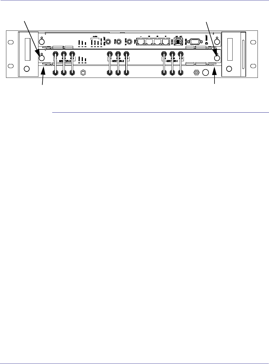
Appendix B l
Replacing a Radio module
B-2 910136 Rev01.00 Standard July 2007
Figure B-1. Radio module replacement
Replacement procedure
1. Disconnect all RF sector cables.
2. Use the #1 phillips-head screwdriver to fully loosen the captive screws on both sides of
the radio module (see Figure B-1).
3. Pinch the locking latches (Figure B-2) at the left and right sides of the module with your
thumbs and forefingers. Pull both latches out to pop the module away from the RN shelf
backplane.
4. Carefully slide the module out and put it aside.
5. Remove the new radio module from its protective electrostatic bag and verify that the pins
located on the rear of the module are straight and have not been damaged in shipping.
6. Insert the radio module in the RN shelf slot and push in until the locking latches meet the
frame.
7. Pinch the locking latches with your thumbs and forefingers so that you can engage the
latches with the frame. Push both latches in until the connector engages the backplane and
the locking latches close securely.
8. Use a phillips head screwdriver to engage and tighten the captive screws on both sides to
hold the radio module in place.
9. Re-attach the RF sector cables.
10. Use the torque wrench to tighten each connector to 1 N-m (9 in-lbs)
11. Follow the procedure RMA process on page B-7 to return the failed module to the Airvana
factory for repair or replacement.
Captive screws
Captive screws
Locking latch Locking latch
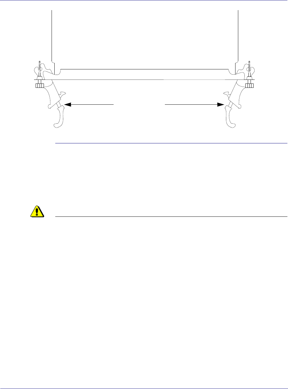
Appendix Bl
Replacing an ADCC module
Airvana ipBTS C30 Installation and Commissioning, Release 4.0 B-3
Figure B-2. Module locking latch detail
Replacing an ADCC module
Use this procedure to replace an ADCC module in an ipBTS C30 shelf.
CAUTION
Replacing an ADCC module causes service disruption. Perform this procedure during a
maintenance window.
Tools required
To replace a radio module you will need the following tools:
• #1 phillips-head screwdriver
• SMA torque wrench
Procedure
To replace an ADCC card, do the following:
1. Use the #1 phillips-head screwdriver to fully loosen the captive screws on both sides of
the ADCC module (see Figure B-1).
2. Pinch the locking latches (Figure B-2) at the left and right sides of the module with your
thumbs and forefingers. Pull both latches out to pop the module away from the RN shelf
backplane.
3. Carefully slide the module out and put it aside.
Locking latches
Module top view

Appendix B l
Replacing a fan in the RN shelf
B-4 910136 Rev01.00 Standard July 2007
4. Remove the new radio module from its protective electrostatic bag and verify that the pins
located on the rear of the module are straight and have not been damaged in shipping.
5. Insert the radio module in the ipBTS chassis slot and push in until the locking latches meet
the frame.
6. Pinch the locking latches with your thumbs and forefingers so that you can engage the
latches with the frame. Push both latches in until the connector engages the backplane and
the locking latches close securely.
7. Use a phillips head screwdriver to engage and tighten the captive screws at top and bottom
to hold the radio module in place.
8. Follow the procedure RMA process on page B-7 to return the failed module to the Airvana
factory for repair or replacement.
Replacing a fan in the RN shelf
If a fan fails in the RN shelf the remaining two fans will go to full power to maintain positive
air flow through the RN shelf.
Tools required
• #1 phillips-head screwdriver
Procedure
To replace a fan module, follow this procedure:
Replacement procedure
1. Use a phillips-head screwdriver to loosen the captive screw (see Figure B-3) on the fan
tray cover.
2. Grasp the fan tray handle and pull the unit straight out of the tray.
3. Slide the new unit into the open slot in the fan tray and push it back until it engages the
power supply in the back of the tray and the latch swings up to close.
4. Tighten the captive screw.
5. Follow the procedure RMA process on page B-7 to return the failed fan to the Airvana
factory for repair or replacement.
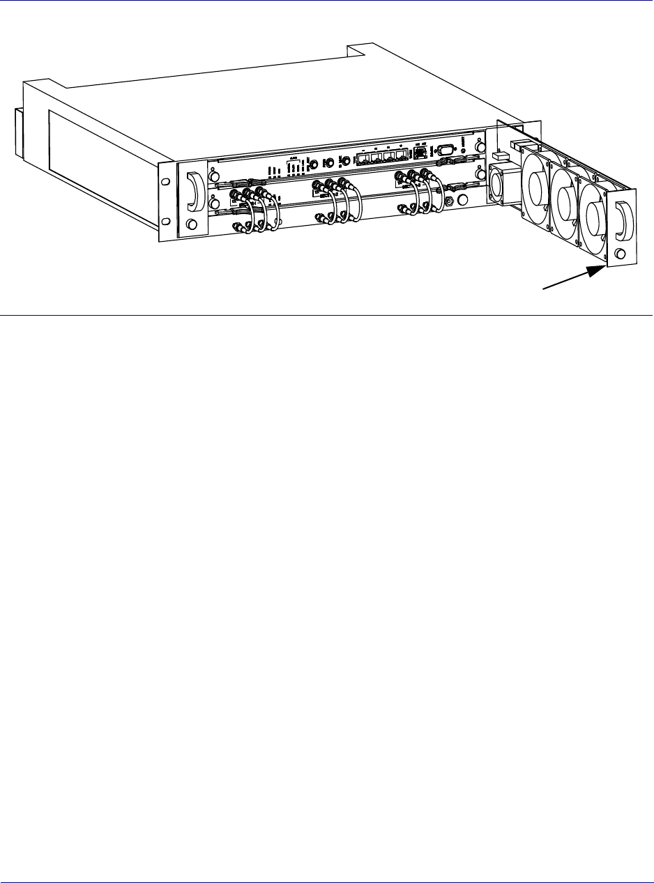
Appendix Bl
Replacing the air filter
Airvana ipBTS C30 Installation and Commissioning, Release 4.0 B-5
Figure B-3. Replacing a fan tray
Replacing the air filter
The air filter in the main filter rack is located at the bottom of the RN shelf. The filter should be
inspected frequently and either cleaned or replaced to maintain a positive cool air flow through
the RN shelf.
Tools required
To replace the air filter you will need the following tools:
• #1 phillips-head screwdriver
To inspect and clean or replace the air filter refer to Figure B-4 as you follow this procedure:
Procedure
1. Grasp the air filter handle with your fingers and pull the filter straight out to remove it
from the metal channel holding it in place.
2. Inspect it for dirt and debris. Replace or clean the filter, as appropriate.
To replace the filter:
3. Insert a new filter so that the back seats securely in the channel in the back of the RN shelf.
Captive screw
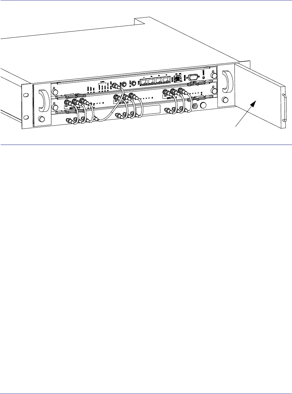
Appendix B l
Replacing the air filter
B-6 910136 Rev01.00 Standard July 2007
P
Figure B-4. Replacing an air filter
Air filter

Appendix Bl
RMA process
Airvana ipBTS C30 Installation and Commissioning, Release 4.0 B-7
RMA process
The Return Materials Authorization (RMA) process provides the approved way to return FRU
modules that have failed or have been damaged in shipping. To return a defective or damaged
ipBTS FRU module follow these steps:
1. Contact your Airvana customer support representative to request an RMA.
2. Customer support troubleshoots the issue to determine whether it is a hardware or
software issue.
If it is a hardware issue the customer support representative processes the RMA order.
The RMA order includes:
• Customer/Operator
• Service Requisition number
• RMA order number
• Serial number of the hardware
• Return type (advanced replacement, like-for-like replacement, or same-for-same
replacement)
• Warranty information
• Root cause analysis, if available
3. Customer returns the hardware which is repaired or replaced and returned based on the
terms of their service contract.

Appendix B l
RMA process
B-8 910136 Rev01.00 Standard July 2007

Airvana ipBTS C30 Installation and Commissioning, Release 4.0 Index-1
Index
A
ADCC
physical specifications, A-3
altitude, A-2
appendix index marker, A-1, B-1
Audience, -2
B
Backhaul links, 1-1
backhauls
loopback, see loopbacks, 4-12
C
Chassis dimensions, 1-2
CLI
diagnostic mode, 4-15
serial
establishing connection, 4-4
Commissioning, 1-1
Core IP network, 1-1
craft
Ethernet, see Ethernet
craft, 4-20
port, 4-2
D
DB-9, 4-2
defined, 1-1
depth, A-1
diagnostic mode in CLI, 4-15
dimensions, A-1
E
Ethernet
craft
configuring IP, 4-20
connecting, 4-21
cross-over cable, 4-1
F
Field replaceable units, 1-4
FRU components, 1-4
FRUs, 1-4
FTP, 4-2
H
height, A-1
Hot-swappable definition, 1-4
Hot-swappable modules, 1-4
HyperTerminal, 4-2
I
Installation, 1-1
IP
Ethernet craft, 4-20
IP network, 1-1
ipBTS 60 description, 1-1
ipBTS overview, 1-1
L
laptop
Ethernet, 4-1
loopbacks
Ethernet, 4-14
understanding, 4-14
internal test, 4-17
testing
the process, 4-12
understanding, 4-13
P
Packet data serving node, 1-1
PDSN, 1-1
PSTN, 1-1
R
RAN, 1-1
ratings, A-2

Index
Index-2 910136 Rev01.00 Standard July 2007
Related documents, -3
Replaceable RN modules, 1-4
RM
physical specifications, A-3
S
serial port, 4-2
Service disrupting definition, 1-4
Service modules, 1-1
spectrum analyzer, 4-2
System controllers, 1-1
T
terminal emulation, 4-2
tests
Ethernet, see loopbacks
Ethernet, 4-14
internal loopback, 4-17
see loopbacks, 4-12
U
UL, A-2
W
weight, A-1
width, A-1
Windows 98, 4-1

Airvana ipBTS C30 Installation and Commissioning, Release 4.0
Backcvr