CommScope Technologies RP-A2014 CB Licensed Transmitter User Manual OneCell HW Install
Airvana, LP CB Licensed Transmitter OneCell HW Install
UserManual.wiki
>
CommScope Technologies
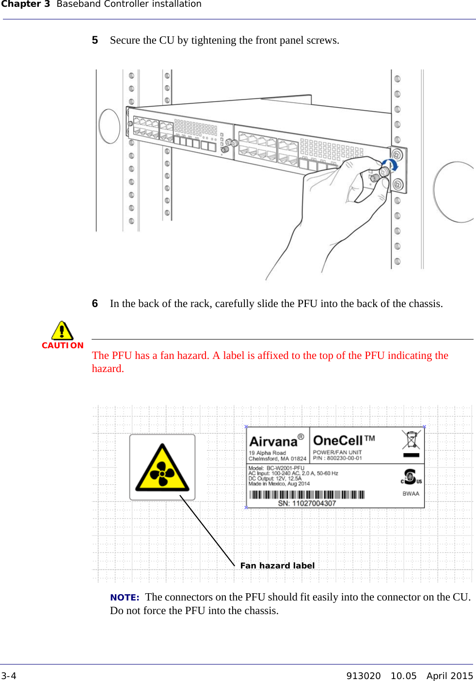
>
RP A2014 User Manual
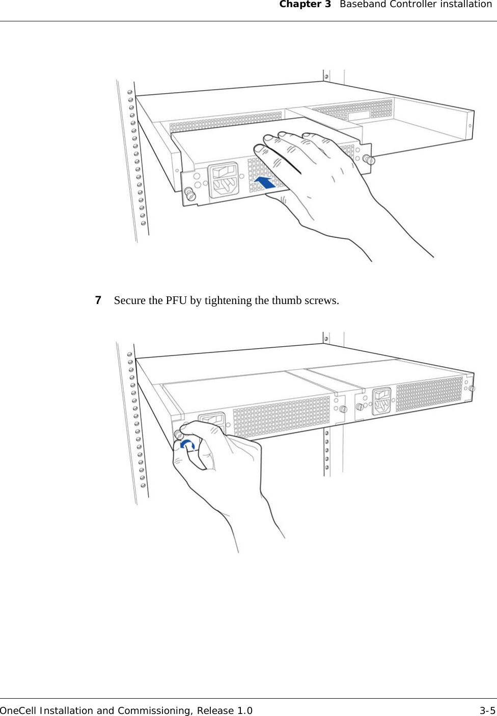
User Manual.pdf
Navigation menu
Upload a User Manual
Namespaces
Wiki Guide
HTML
PDF
Info
Views
User Manual
Discussion / Help
Navigation
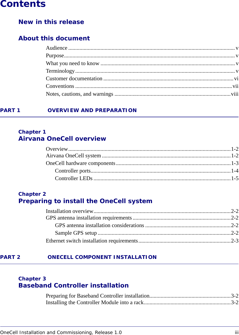


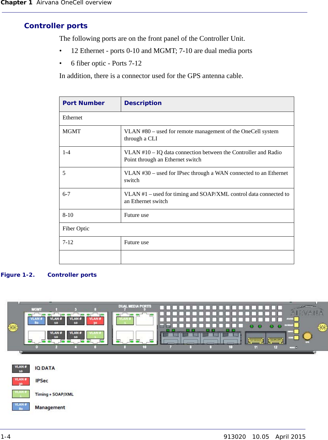
![About this document OneCell Installation and Commissioning, Release 1.0 viiDRAFTConventionsThis guide uses the following text conventions, as applicable.OneCell On-site Troubleshooting (913027) Describes symptoms and troubleshooting methods at the enterprise level, including basic on location troubleshooting up to the core, and when to call next level of support.OneCell Deployment Guide (913028) Contains the device network overview, including Airvana provided components and required components from other vendors, DMS overview, and device overview and requirements. Table 1. Customer documentation (continued)Title ContentsTable 2. ConventionsConvention DescriptionSyntax symbols< > Enclose a required parameter or set of parameters. For example:>band-class <class><class> is a required parameter.[ ] Enclose an optional parameter or set of parameters. For example:>activate image <version> [reboot][reboot] is an optional parameter. | Separates items on a list of parameters, only one of which can be used. For example:>channel-included <yes|no>A valid command is:>channel-included yes](https://usermanual.wiki/CommScope-Technologies/RP-A2014/User-Guide-2715450-Page-13.png)


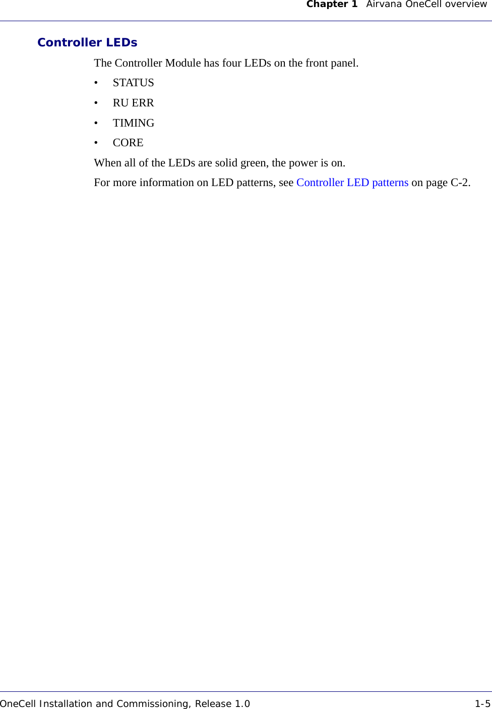


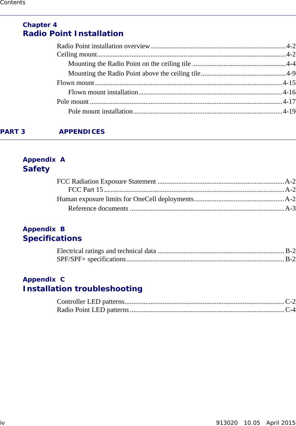
![Appendix A Safety OneCell Installation and Commissioning, Release 1.0 A-3DRAFTReference documents[1] Federal Communications Commission Document OET Bulletin 65, Supplement C, 2001, Evaluating Compliance with FCC guidelines for Human Exposure to radio frequency Electromagnetic Fields, US Federal Communications Commission, Office of Engineering and Technology June 2001.[2] Federal Communications Commission Document OET Bulletin 56, “Questions and answers about biological effects and potential hazards of radio frequency electromagnetic fields”, Federal Communications Commission Office of Engineering and Technology, August 1999.[3] ICNIRP Guidelines for limiting exposure to time varying electric, magnetic and electromagnetic fields up to 300 GHz. International Commission on Non Ionizing Radiation, published in Health Physics 74 (4): 494-522; 1998[4] ICNIRP Statement on EMF-Emitting New Technologies, International Commission on Non-Ionizing Radiation, published in Health Physics 94 (4):376-392, 2008[5] 3GPP Document 3GPP TS 36.104 version 10.11.0 Release 10,” LTE Evolved Universal Terrestrial Radio Access (E-UTRA); Base Station (BS) radio transmission and reception”Table A-1. RF exposure for OneCell at maximum power internal antennasParameter Value for One RP Value for Two RPsTx Power (dBm) per antenna 23 23Tx Loss (dB) 0 0Tx Antenna Gain 2 4Multi-operator Combiner Loss 0 – 6Transmitter Duty Cycle % 100 100Number of Antennas (MIMO) 2 2Contribution due to multiple antennas (dB) 3.010299957 3.010299957Power Increase due to multiple RPs (dB) 0 6.020599913Derived Total EIRP (dBW) -1.989700043 0.03089987Frequency (MHz) 1900 1900Point Source Total EIRP (watts) 0.632455532 1.007140329Target W/m^2 9.5 9.5](https://usermanual.wiki/CommScope-Technologies/RP-A2014/User-Guide-2715450-Page-61.png)