CommScope Technologies RP-A2014 CB Licensed Transmitter User Manual OneCell HW Install
Airvana, LP CB Licensed Transmitter OneCell HW Install
User Manual.pdf

DRAFT
Installation and Commissioning
Release 1.0
Document Number: 913020
Document Revision: 10.05
Date: April 2015
OneCell

ii 913020 10.05 April 2015
DRAFT
Copyright 2015 Airvana LP. All rights reserved.
Airvana is a registered trademark of Airvana LP (“Airvana”). All other trademarks are trademarks of
their respective owners.
This document contains information that is the property of Airvana . This document may not be copied,
reproduced, reduced to any electronic medium or machine readable form, or otherwise duplicated, and
the information herein may not be used, disseminated or otherwise disclosed, except with the prior
written consent of Airvana.
THE SPECIFICATIONS AND INFORMATION REGARDING THE PRODUCTS IN THIS MANUAL ARE SUBJECT
TO CHANGE WITHOUT NOTICE. ALL STATEMENTS, INFORMATION, AND RECOMMENDATIONS IN THIS
MANUAL ARE BELIEVED TO BE ACCURATE BUT ARE PRESENTED WITHOUT WARRANTY OF ANY KIND,
EXPRESS OR IMPLIED. USERS MUST TAKE FULL RESPONSIBILITY FOR THEIR APPLICATION OF ANY
PRODUCTS.
THE SOFTWARE LICENSE AND LIMITED WARRANTY FOR THE ACCOMPANYING PRODUCT ARE SET
FORTH IN THE INFORMATION PACKET THAT SHIPPED WITH THE PRODUCT AND ARE INCORPORATED
HEREIN BY REFERENCE. IF YOU ARE UNABLE TO LOCATE THE SOFTWARE LICENSE OR LIMITED
WARRANTY, CONTACT YOUR AIRVANA SALES REPRESENTATIVE FOR A COPY.

OneCell Installation and Commissioning, Release 1.0 iii
DRAFT
Contents
New in this release
About this document
Audience .......................................................................................................................v
Purpose..........................................................................................................................v
What you need to know ................................................................................................v
Terminology..................................................................................................................v
Customer documentation .............................................................................................vi
Conventions ................................................................................................................vii
Notes, cautions, and warnings ...................................................................................viii
PART 1 OVERVIEW AND PREPARATION
Chapter 1
Airvana OneCell overview
Overview....................................................................................................................1-2
Airvana OneCell system ............................................................................................1-2
OneCell hardware components..................................................................................1-3
Controller ports....................................................................................................1-4
Controller LEDs ..................................................................................................1-5
Chapter 2
Preparing to install the OneCell system
Installation overview..................................................................................................2-2
GPS antenna installation requirements......................................................................2-2
GPS antenna installation considerations .............................................................2-2
Sample GPS setup ...............................................................................................2-2
Ethernet switch installation requirements..................................................................2-3
PART 2 ONECELL COMPONENT INSTALLATION
Chapter 3
Baseband Controller installation
Preparing for Baseband Controller installation..........................................................3-2
Installing the Controller Module into a rack..............................................................3-2

Contents
iv 913020 10.05 April 2015
DRAFT
Chapter 4
Radio Point Installation
Radio Point installation overview..............................................................................4-2
Ceiling mount.............................................................................................................4-2
Mounting the Radio Point on the ceiling tile ......................................................4-4
Mounting the Radio Point above the ceiling tile.................................................4-9
Flown mount............................................................................................................4-15
Flown mount installation...................................................................................4-16
Pole mount ...............................................................................................................4-17
Pole mount installation......................................................................................4-19
PART 3 APPENDICES
Appendix A
Safety
FCC Radiation Exposure Statement .........................................................................A-2
FCC Part 15........................................................................................................A-2
Human exposure limits for OneCell deployments....................................................A-2
Reference documents .........................................................................................A-3
Appendix B
Specifications
Electrical ratings and technical data .........................................................................B-2
SPF/SPF+ specifications...........................................................................................B-2
Appendix C
Installation troubleshooting
Controller LED patterns............................................................................................C-2
Radio Point LED patterns.........................................................................................C-4

Contents
OneCell Installation and Commissioning, Release 1.0 v
DRAFT

List of figures
i913020 10.05 April 2015
DRAFT
List of figures
Figure 1-1 OneCell Deployment .......................................................................1-3
Figure 1-2 Controller ports................................................................................1-4
Figure 2-1 GPS antenna setup...........................................................................2-3
Figure 4-1 Airvana ceiling mount kit contents..................................................4-2
Figure 4-2 On-ceiling mounting hardware, system integrator provided...........4-3
Figure 4-3 Above ceiling mount hardware, system integrator provided...........4-3
Figure 4-4 Mounting bracket kit contents .......................................................4-16
Figure 4-5 Mounting bracket kit contents .......................................................4-18

List of tables
OneCell Installation and Commissioning, Release 1.0 i
DRAFT
List of tables
Table 1 Customer documentation .....................................................................vi
Table 2 Conventions ........................................................................................vii
Table A-1 RF exposure for OneCell at maximum power internal antennas ......A-3

List of tables
ii 913020 10.05 April 2015
DRAFT

OneCell Installation and Commissioning, Release 1.0 iii
DRAFT
New in this release
The following section lists documentation changes in OneCell Hardware Installation
and Configuration (913025) for R1.0.
Revision 10.05
• Added new chapter, Chapter 4, Radio Point Installation
Revision 10.04
•Chapter 3, Baseband Controller installation
— Added caution to Installing the Controller Module into a rack on page 3-2
— Added caution and drawing to step 6 on page 3-4
•Appendix B, Specifications
— Added topic, Electrical ratings and technical data on page B-2
Revision 10.03
• Added content to Chapter 4, Radio Point Installation
Revision 10.02
• Added new chapter, Chapter 4, Radio Point Installation
Revision 10.01
• Initial document release

New in this release
iv 913020 10.05 April 2015
DRAFT

OneCell Installation and Commissioning, Release 1.0 v
DRAFT
About this document
This document provides the procedures for installing and configuring the Controller
Unit and Radio Points.
Audience
This document is written for computer hardware installers and administrators,
network architects and business planners who are responsible for the planning and
design of the Airvana OneCell deployment environment.
Purpose
This guide provides the information necessary for installing the OneCell hardware in
the operator’s network.
What you need to know
The reader should have a basic understanding of:
• Data networks
• LTE technology
• General telecommunications practices
Terminology
This guide uses the following hardware-specific terminology.

About this document
vi 913020 10.05 April 2015
DRAFT
Customer documentation
The following table lists available documents in the OneCell documentation suite.
Name Definition
Hot-swappable Hot-swappable components can be installed or removed
while the system is running, without using any software
commands.
Hot-pluggable Using the proper software commands, you can install or
remove hot-pluggable components while the system is
running.
FRU Field-replaceable units must be removed and installed only
by authorized Oracle service personnel.
CRU Customer-replaceable units can be removed and replaced by
any qualified service provider.
Table 1. Customer documentation
Title Contents
OneCell CLI Reference (913020) Describes the Switched IQ CLI commands including
parameters, syntax, and sample output.
OneCell System Troubleshooting
(913022) Cover common troubleshooting scenarios in deployed
devices and troubleshooting methods.
OneCell Network Planning Guide
(913023) Describes main components of the Switched IQ
system, high-level view of HW components, how do
you engineer an in-building system, how do you
determine RU locations, how to design in-building
systems and how to determine Radio Point locations.
Contains best practices for deployment, including
when to use clustering, and how to manage capacity.
OneCell Hardware Installation
and Configuration (913025) Includes detailed installation instructions for
Controller Unit and Radio Points hardware, planning
the installation, physical install, how to configure the
installation, commissioning the installation to service;
verification tests after the installation.
OneCell Administration (913026) Contains enterprise-level monitoring and alarms.

About this document
OneCell Installation and Commissioning, Release 1.0 vii
DRAFT
Conventions
This guide uses the following text conventions, as applicable.
OneCell On-site Troubleshooting
(913027) Describes symptoms and troubleshooting methods at
the enterprise level, including basic on location
troubleshooting up to the core, and when to call next
level of support.
OneCell Deployment Guide
(913028) Contains the device network overview, including
Airvana provided components and required
components from other vendors, DMS overview, and
device overview and requirements.
Table 1. Customer documentation (continued)
Title Contents
Table 2. Conventions
Convention Description
Syntax symbols
< > Enclose a required parameter or set of parameters. For
example:
>band-class <class>
<class> is a required parameter.
[ ] Enclose an optional parameter or set of parameters. For
example:
>activate image <version> [reboot]
[reboot] is an optional parameter.
| Separates items on a list of parameters, only one of
which can be used. For example:
>channel-included <yes|no>
A valid command is:
>channel-included yes

About this document
viii 913020 10.05 April 2015
DRAFT
Notes, cautions, and warnings
NOTE
Notes provide additional information about the subject text.
Font usage
Bold input font Indicates text that must be entered exactly as shown. For
example:
Enter ping 192.23.10.12.
Italic input font Indicates a variable parameter for which you must
provide an actual value. For example:
>authentication key <aukey>
<aukey> is a variable parameter.
A valid command is:
>authentication key 9782503000
Plain output font Indicates system output in a command line or system-
generated file. For example:
IP address 192.23.10.12 is alive.
Italic output font Indicates a variable in system output in a command line
or system-generated file. For example:
Installation of release <release> is
complete.
Plain italic font Indicates file names, directory paths, book titles, chapter
titles, and user accounts.
Bold font Indicates text that appears on screen exactly as shown,
for example, names of screens, names of buttons, items
on menus, and items on pull down lists.
blue text Indicates a hypertext link.
Other conventions
> Indicates graphical user interface (GUI) menu path. For
example:
Select Edit > Add Network to open the Add Network
screen.
Table 2. Conventions (continued)
Convention Description

About this document
OneCell Installation and Commissioning, Release 1.0 ix
DRAFT
CAUTION
Cautions indicate that procedures, if performed incorrectly, can cause equipment
damage or data loss.
WARNING
Warnings indicate that procedures, if performed incorrectly, can harm you.

About this document
x913020 10.05 April 2015
DRAFT
DRAFT


Chapter 1 Airvana OneCell overview
1-2 913020 10.05 April 2015
DRAFT
Overview
OneCell is a revolutionary wireless system that can deliver the ultimate in wireless
performance.
• It eliminates cell borders and handovers
• It can cover a large area with consistent user experience without any significant
interference
• It can take advantage of multiple distributed radio points to deliver a stronger
signal on both the downlink and the uplink
• It can deliver greater capacity through distributed (multi-user and single-user)
MIMO and Coordinated Multipoint (CoMP)
• It has the flexibility to neutralize macro interference in co-channel small cell
deployments
• It can be used to deliver unprecedented levels of capacity to hot spot areas by
deploying radio points with overlapping coverage and enabling multi- user MIMO
In addition to these important benefits in user experience and data capacity, OneCell
provides superior economics and investment protection, ease of deployment, support
for multi-operator deployments.
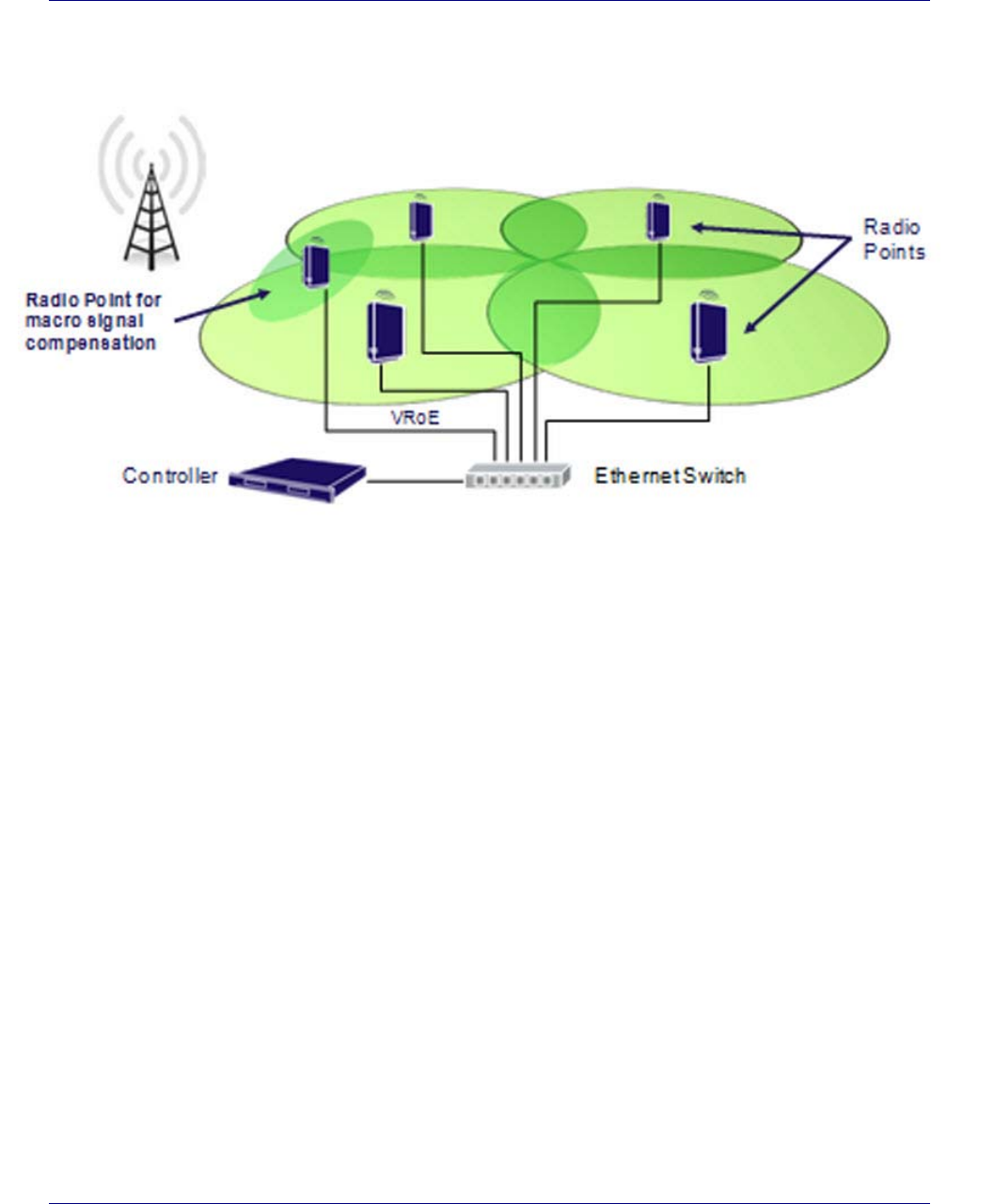
Airvana OneCell system
OneCell is an in-building, enterprise solution for LTE that provides an in-building
consistent signal. It operates as a wireless network with a single cell, called a
controller, over distributed radio points. Network operators benefit from the OneCell
because they reduce the load on their infrastructure.
Chapter 1 Airvana OneCell overview
OneCell Installation and Commissioning, Release 1.0 1-3
DRAFT
Figure 1-1. OneCell Deployment
OneCell hardware components
The OneCell hardware consists of the following components:
• Baseband Controller
— Chassis
— Controller Unit (CU)
— Power Fan Unit (PFU)
• Radio Points (RP)
Chapter 1 Airvana OneCell overview
1-4 913020 10.05 April 2015
DRAFT
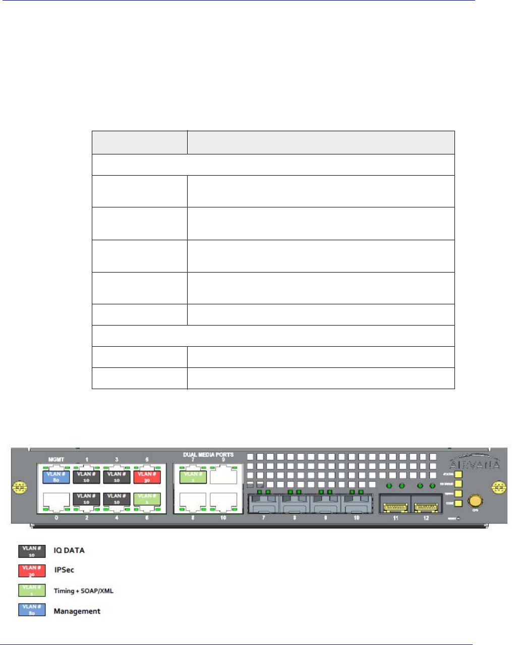
Controller ports
The following ports are on the front panel of the Controller Unit.
• 12 Ethernet - ports 0-10 and MGMT; 7-10 are dual media ports
• 6 fiber optic - Ports 7-12
In addition, there is a connector used for the GPS antenna cable.
Figure 1-2. Controller ports
Port Number Description
Ethernet
MGMT VLAN #80 – used for remote management of the OneCell system
through a CLI
1-4 VLAN #10 – IQ data connection between the Controller and Radio
Point through an Ethernet switch
5 VLAN #30 – used for IPsec through a WAN connected to an Ethernet
switch
6-7 VLAN #1 – used for timing and SOAP/XML control data connected to
an Ethernet switch
8-10 Future use
Fiber Optic
7-12 Future use

Chapter 1 Airvana OneCell overview
OneCell Installation and Commissioning, Release 1.0 1-5
DRAFT
Controller LEDs
The Controller Module has four LEDs on the front panel.
•STATUS
•RU ERR
•TIMING
•CORE
When all of the LEDs are solid green, the power is on.
For more information on LED patterns, see Controller LED patterns on page C-2.

Chapter 1 Airvana OneCell overview
1-6 913020 10.05 April 2015
DRAFT


Chapter 2 Preparing to install the OneCell system
2-2 913020 10.05 April 2015
DRAFT
Overview
This document describes the OneCell installation and includes:
•Chapter 3, Baseband Controller installation
•Chapter 4, Radio Point Installation
Before installing the OneCell components
Before installing the OneCell components, the system integrator must plan the
network for the topology that will be deployed. See
DRAFT

OneCell Installation and Commissioning, Release 1.0 3-1
DRAFT
Chapter 3
Baseband Controller installation
This chapter contains the Baseband Controller installation procedures, including
chassis installation into a rack, Controller Unit and Power Fan Unit installation into
the chassis and the cables required for a basic installation.
Preparing for Baseband Controller installation 3-2
Installing the Controller Module into a rack 3-2
Chapter 3 Baseband Controller installation
3-2 913020 10.05 April 2015
DRAFT
Preparing for Baseband Controller installation
Open the shipping box. It should have the components for one complete Controller
Unit:
• Chassis – including four mounting screws
• Controller Unit (CU)
• Power Fan Unit (PFU)
The Baseband Controller is 1U high. Be sure there is enough room for the Controller
Unit in the rack.
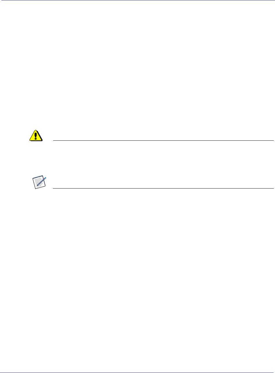
Installing the Controller Module into a rack
CAUTION
The controller, when mounted, must in the horizontal position. No other
orientations are allowed.
NOTE
The chassis requires four screws to secure it into the rack.
1Slide the chassis into the rack.
2Line up the holes in the chassis ears to the holes in the rack.
Chapter 3 Baseband Controller installation
OneCell Installation and Commissioning, Release 1.0 3-3
DRAFT
3Secure the chassis with the screws.
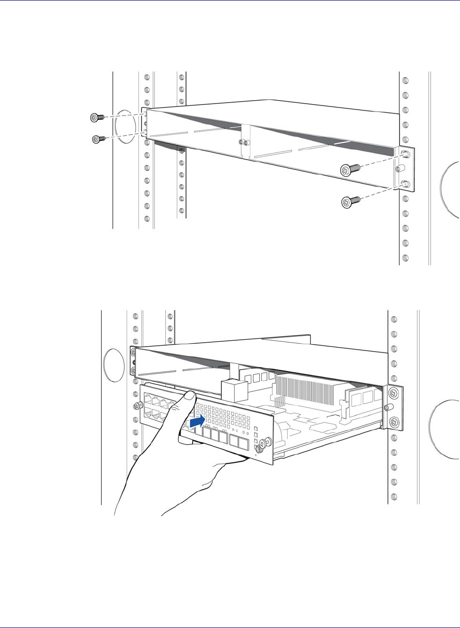
4Carefully slide the CU into the front of the chassis.
Chapter 3 Baseband Controller installation
3-4 913020 10.05 April 2015
DRAFT
5Secure the CU by tightening the front panel screws.
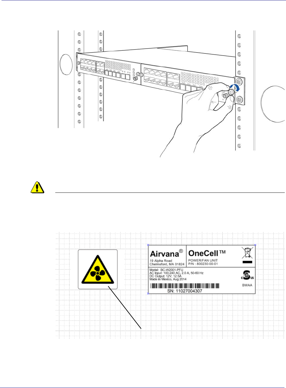
6In the back of the rack, carefully slide the PFU into the back of the chassis.
CAUTION
The PFU has a fan hazard. A label is affixed to the top of the PFU indicating the
hazard.
NOTE: The connectors on the PFU should fit easily into the connector on the CU.
Do not force the PFU into the chassis.
Fan hazard label
Chapter 3 Baseband Controller installation
OneCell Installation and Commissioning, Release 1.0 3-5
DRAFT
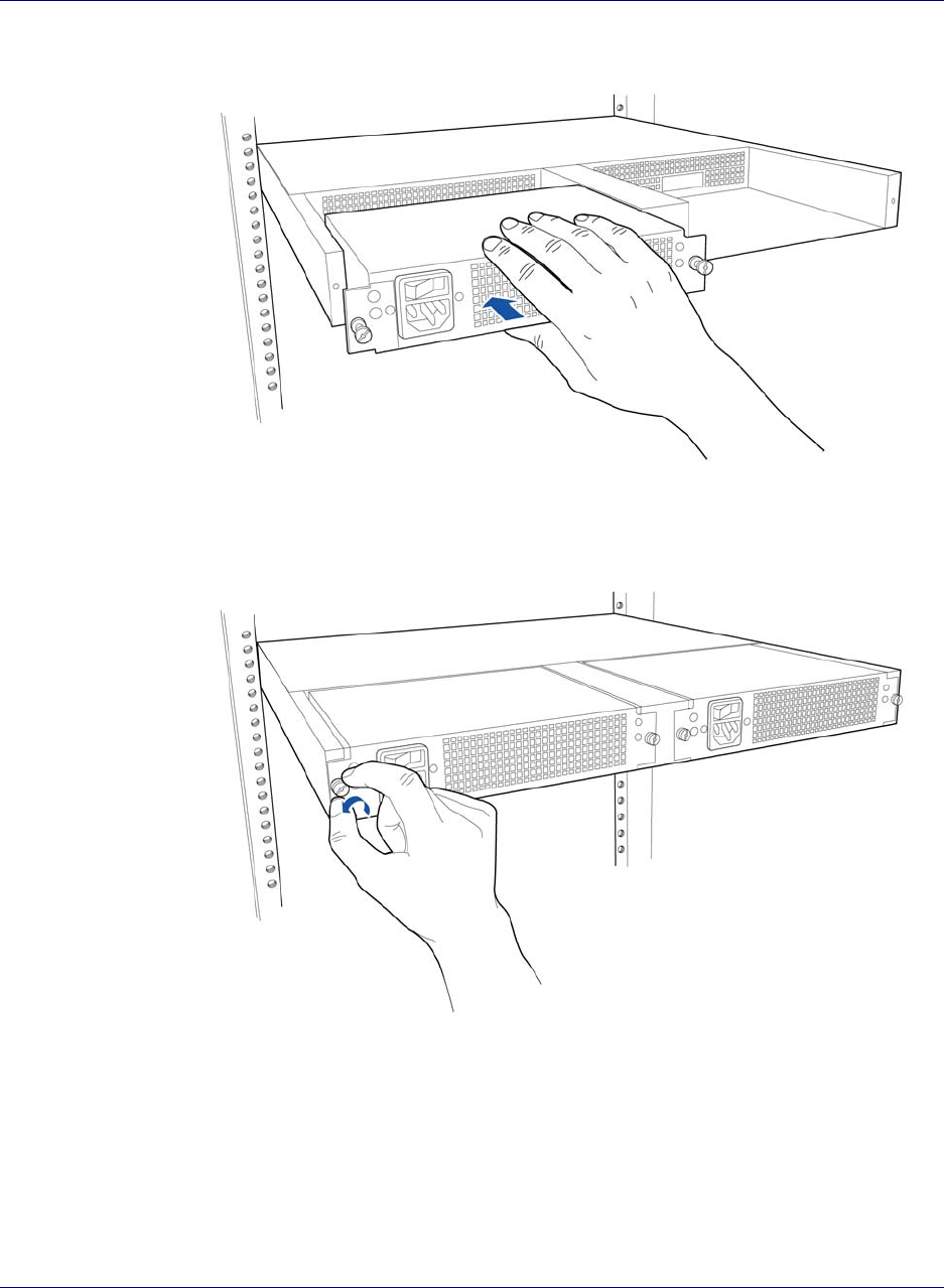
7Secure the PFU by tightening the thumb screws.
Chapter 3 Baseband Controller installation
3-6 913020 10.05 April 2015
DRAFT
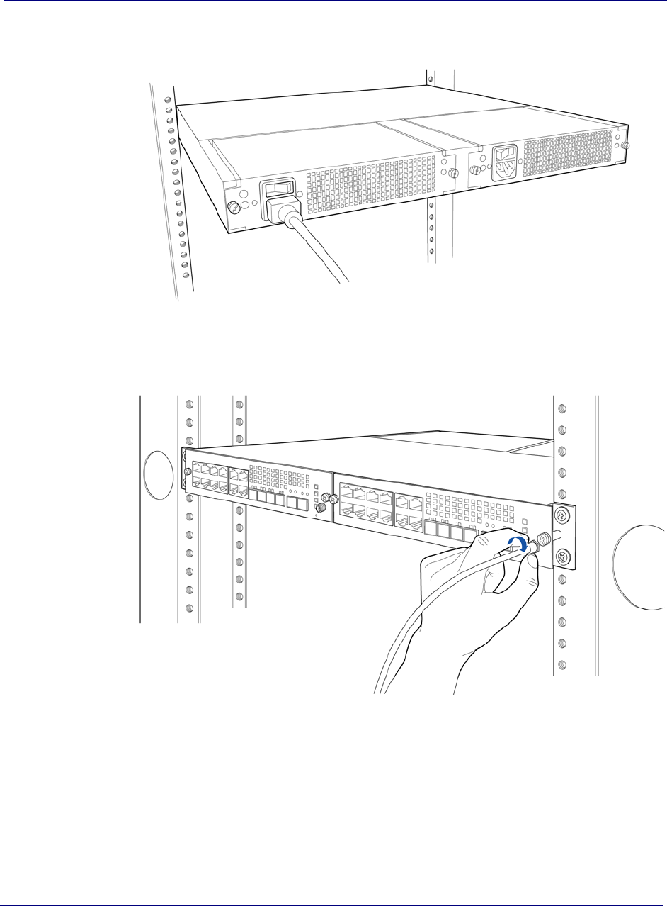
8Connect the power cord to the PFU.
9On the Controller’s front panel, connect the GPS antenna cable.
Chapter 3 Baseband Controller installation
OneCell Installation and Commissioning, Release 1.0 3-7
DRAFT
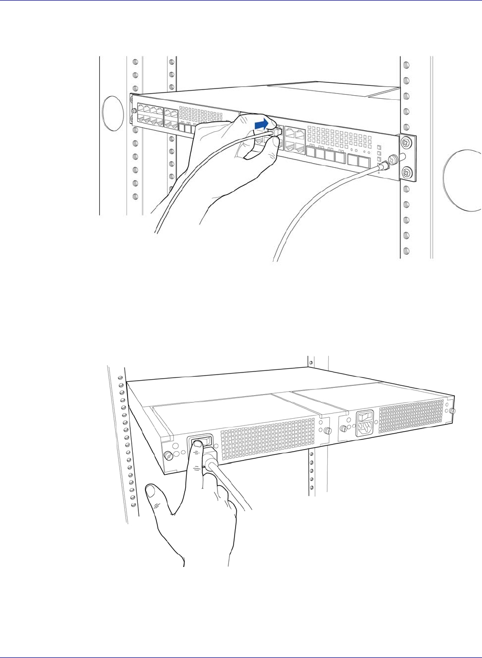
10 Connect the Ethernet or fiber optic cable to the appropriate port.
11 On the back of the Controller (PFU), turn on the power.
The LEDs on the front panel will be solid green, when the power is on. If none are on,
check your power connection. If the LED pattern is other than all green, see Controller
LED patterns on page C-2.

Chapter 3 Baseband Controller installation
3-8 913020 10.05 April 2015
DRAFT

Chapter 4 Radio Point Installation
4-2 913020 10.05 April 2015
DRAFT
Radio Point installation overview
There are four configurations for installing the Radio Point, which are dependent on
the ceiling type.
• Ceiling mount, on tile
• Ceiling mount, above tile
•Flown mount
•Pole mount
Ceiling mount
Mounting the Radio Point (RP) above or on the ceiling tile requires the following
hardware provided by Airvana:
• Radio Point plate and screws
• Mounting plate screws
Figure 4-1. Airvana ceiling mount kit contents
Mounting the Radio Point (RP) above or on the ceiling tile requires the following
hardware provided by the system integrator:
• 4" octagon box, 1-1/2" deep with 1/2" side cutouts
• Drop rail – Eaton B-line BA50 recommended
•Clamp
• Mounting screw
Radio Point plate
with four screws
Mounting plate with
two screws
Chapter 4 Radio Point Installation
OneCell Installation and Commissioning, Release 1.0 4-3
DRAFT
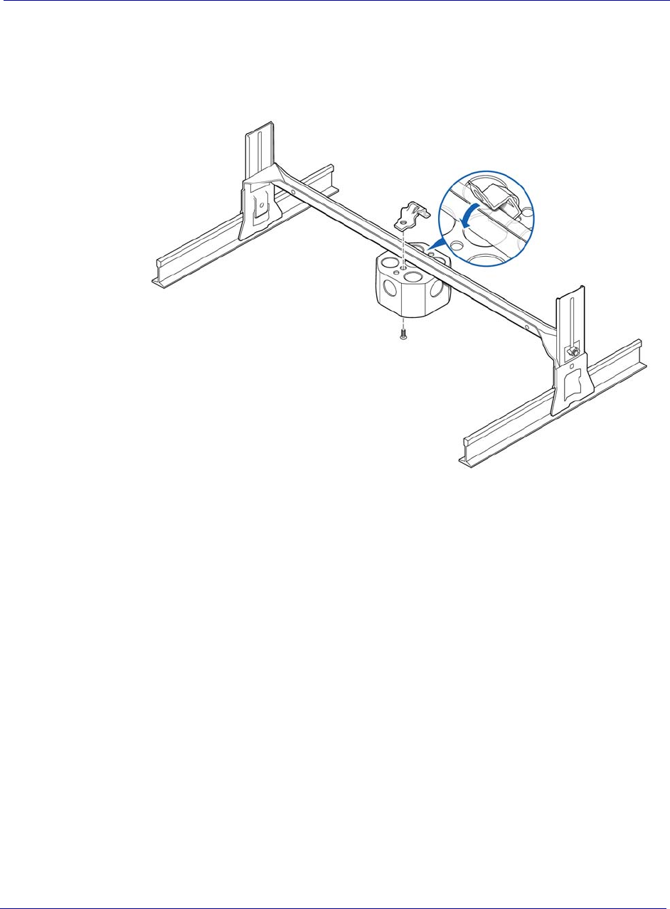
Figure 4-2. On-ceiling mounting hardware, system integrator provided
Figure 4-3. Above ceiling mount hardware, system integrator provided
z
Drop rail
Clamp
Screw
Octagon box
Drop rail
Clamp
Screw
Octagon box
Chapter 4 Radio Point Installation
4-491302010.05 April 2015
DRAFT
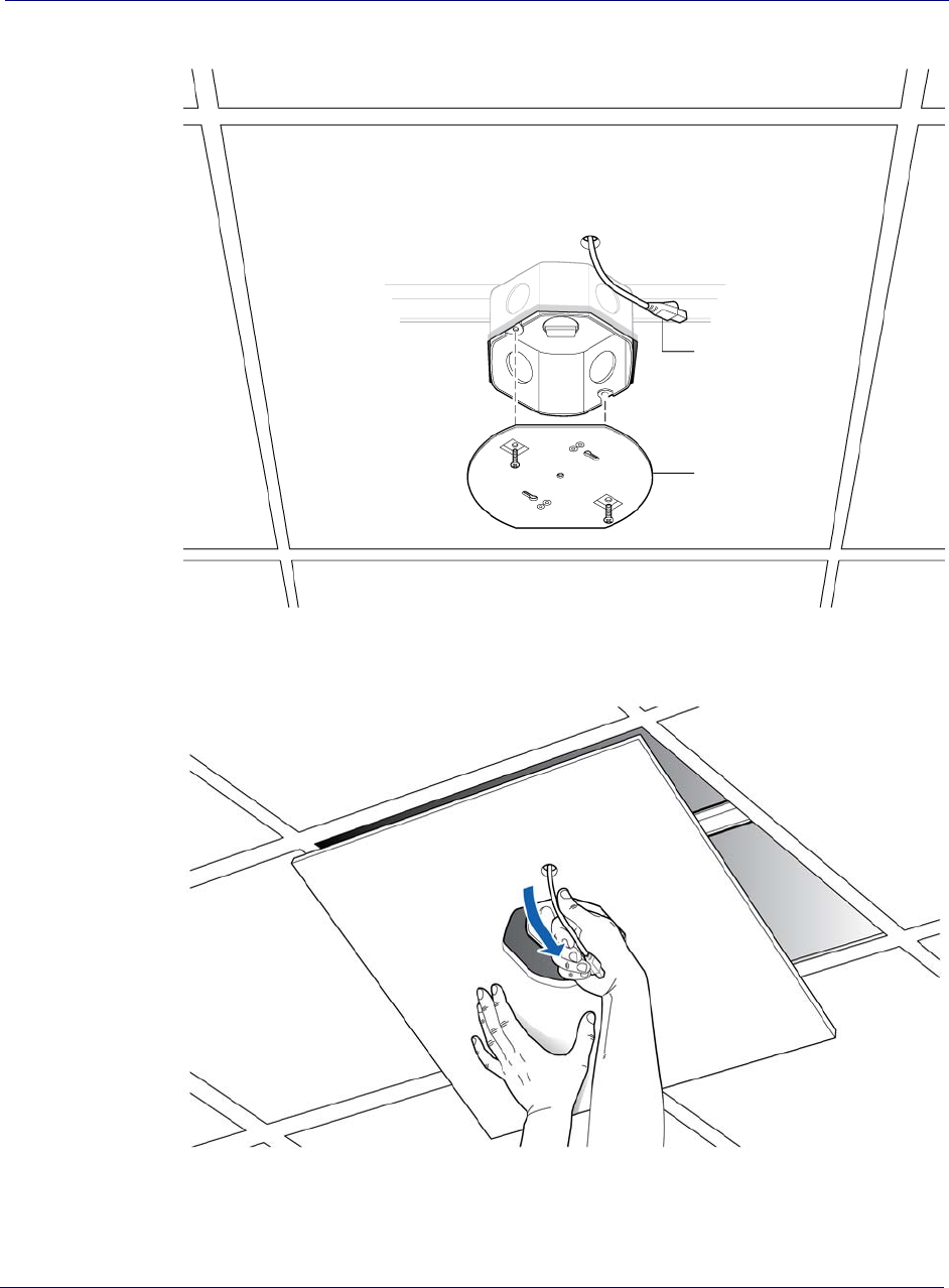
Mounting the Radio Point on the ceiling tile
1Remove ceiling tile from the overhead.
2Cut 5” diameter hole to fit a 4-inch octagon box and drill a 1/2” diameter hole for the Ethernet
cable pass-through.
NOTE:Use a 1-1/2 deep RACO 8125 or equivalent.
TIP
Trace the outline of the octagon box on the ceiling tile.
Use the mounting plate as a guide on the ceiling tile.
Chapter 4 Radio Point Installation
5-40.1 esaeleR ,gninoissimmoC dna noitallatsnI lleCenO
DRAFT
3Attach the octagon box to the ceiling bracket using a clamp and screw.
NOTE:Airvana recommends the Eaton B-line – BA50 bracket.
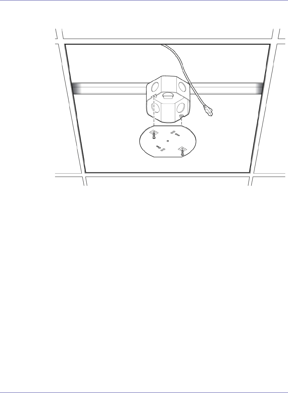
4Attach the mounting plate onto the octagon box.
Ceiling
bracket
Octagon box
Screw
Drop ceiling rail
Clamp
Chapter 4 Radio Point Installation
4-6 913020 10.05 April 2015
DRAFT
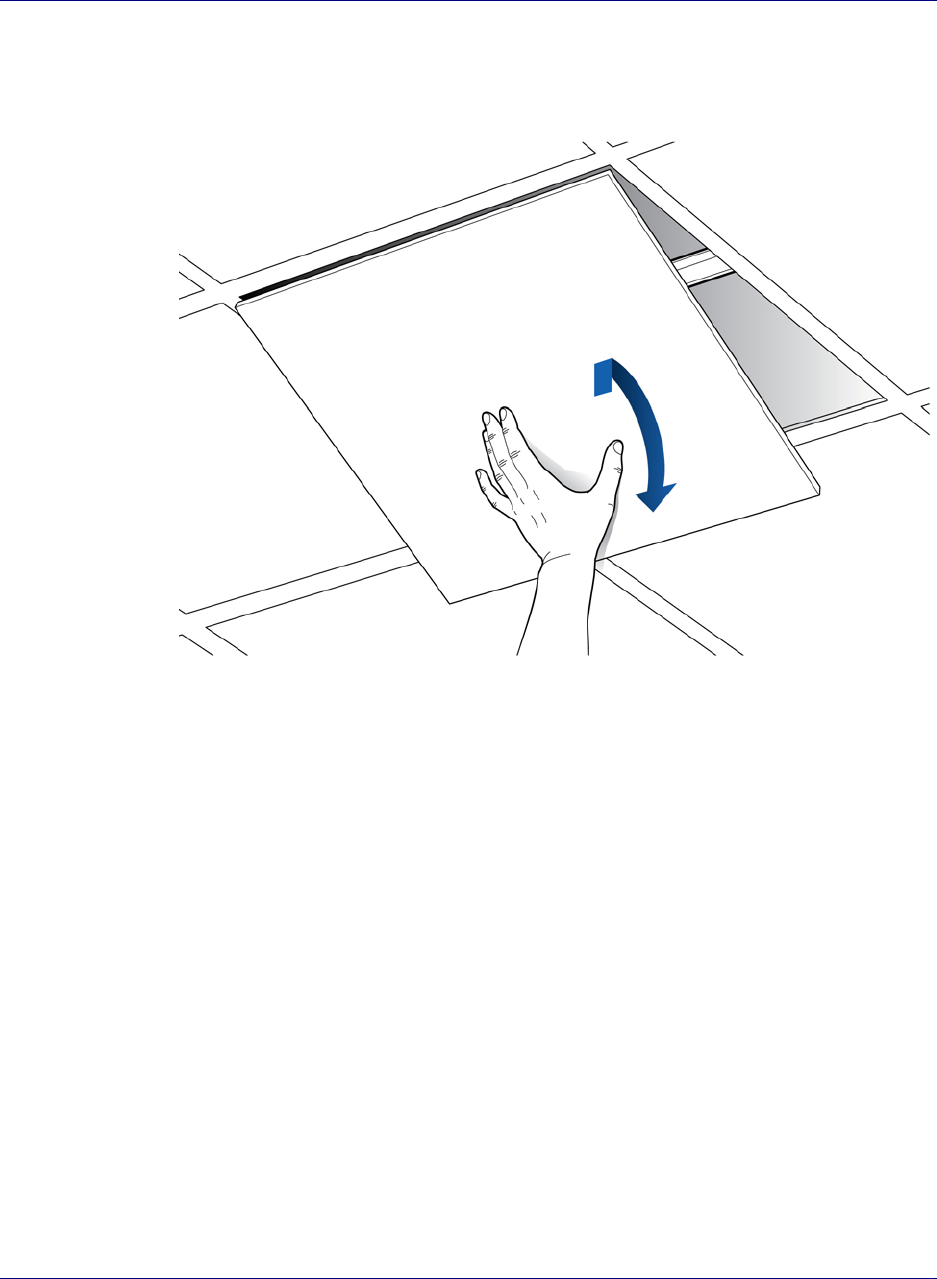
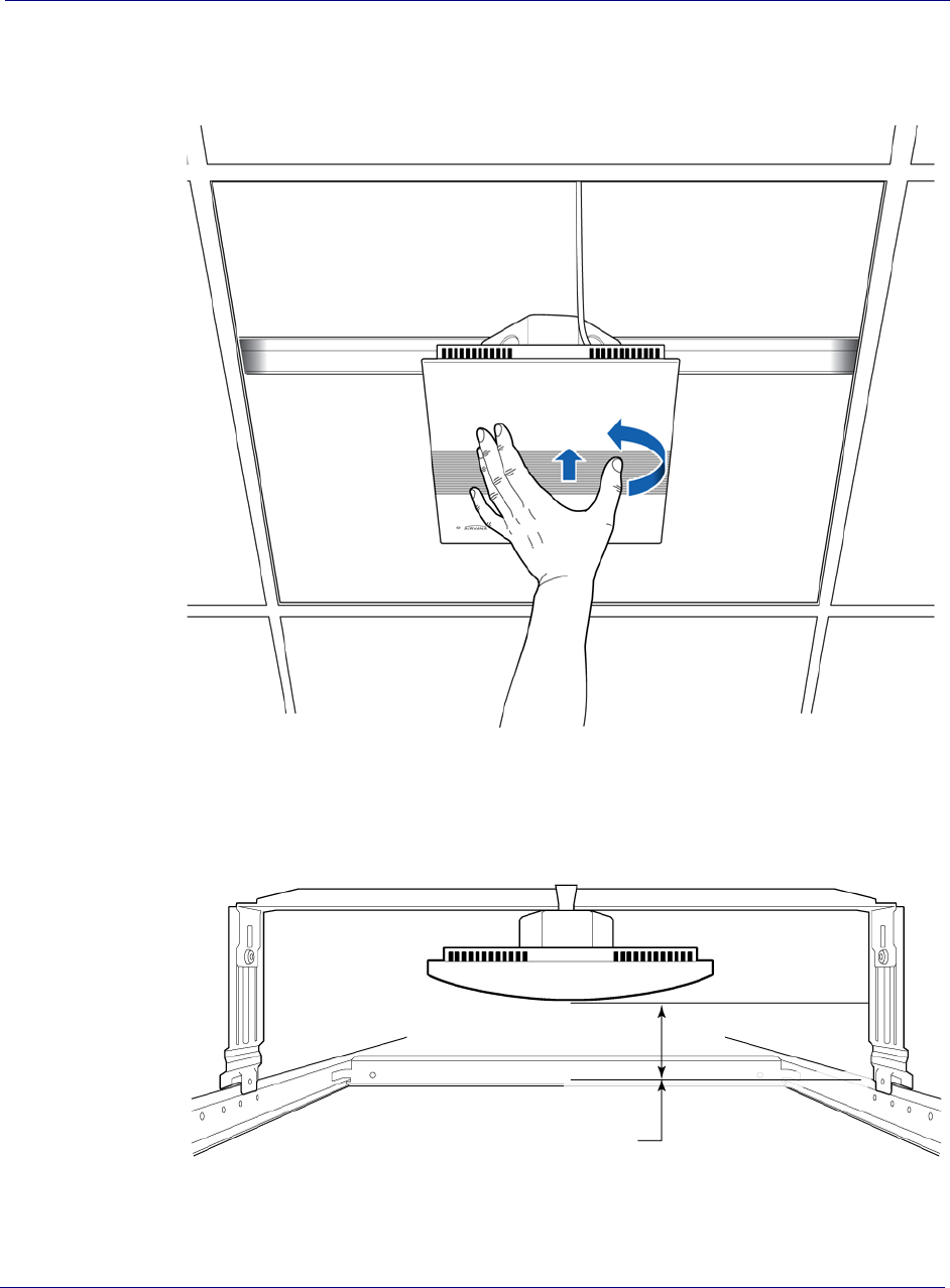
5Replace the ceiling tile and pull the Ethernet cable through the ceiling tile.
Ethernet cable
Mounting plate
Chapter 4 Radio Point Installation
7-40.1 esaeleR ,gninoissimmoC dna noitallatsnI lleCenO
DRAFT
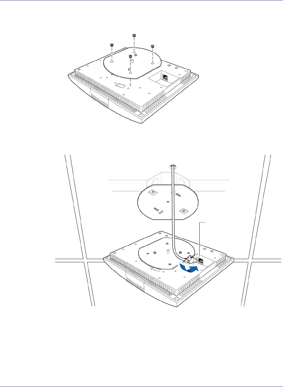
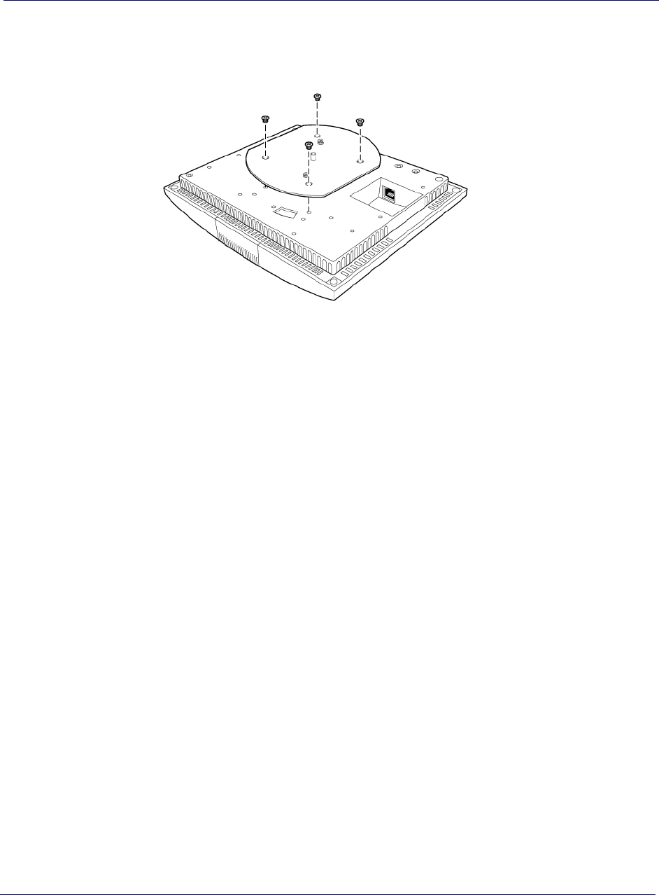
6Attach base plate to the Radio Point. Apply Thread locking compound to screws
prior to installation.
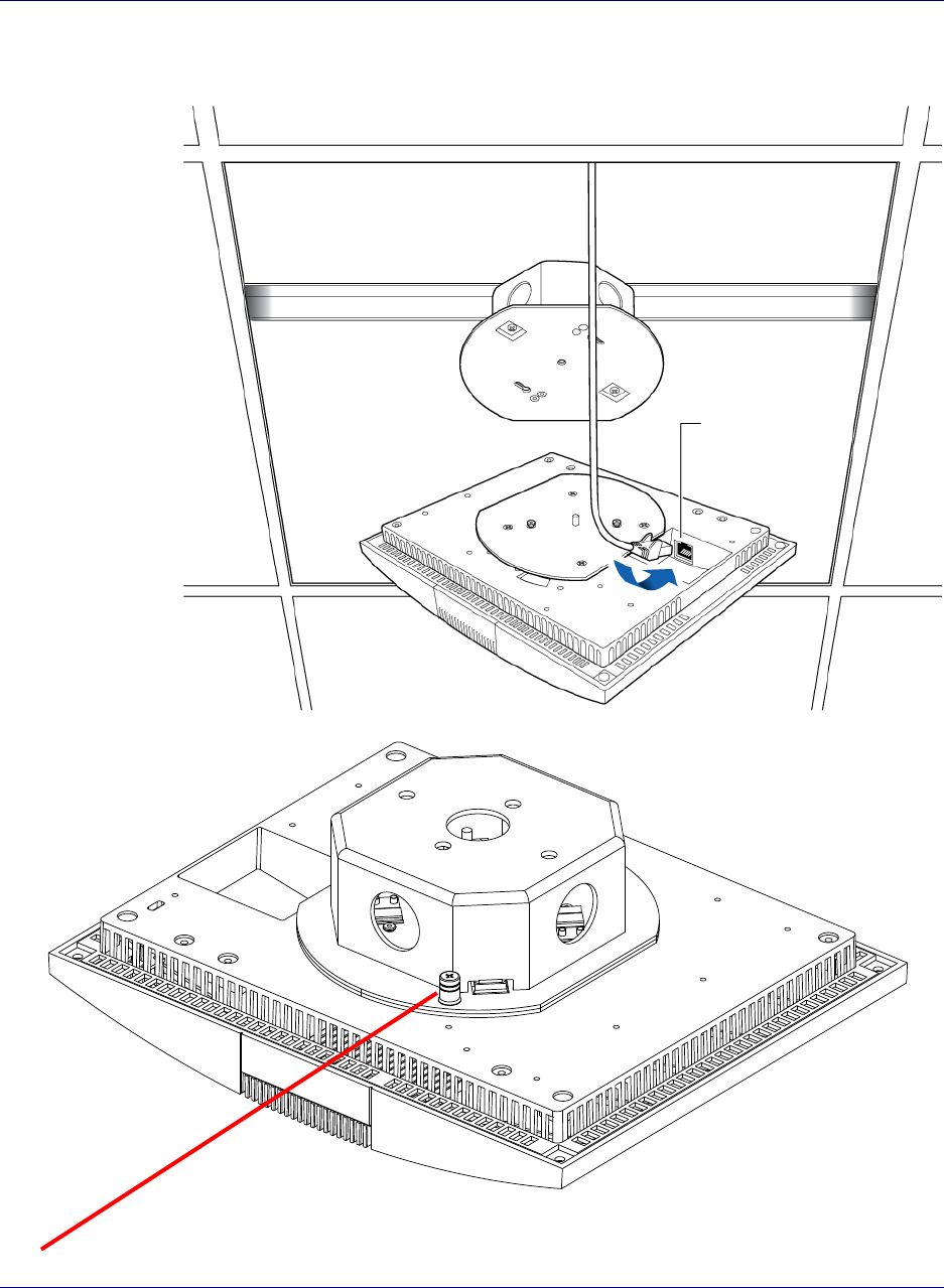
7Attach the Ethernet cable to the Radio Point.
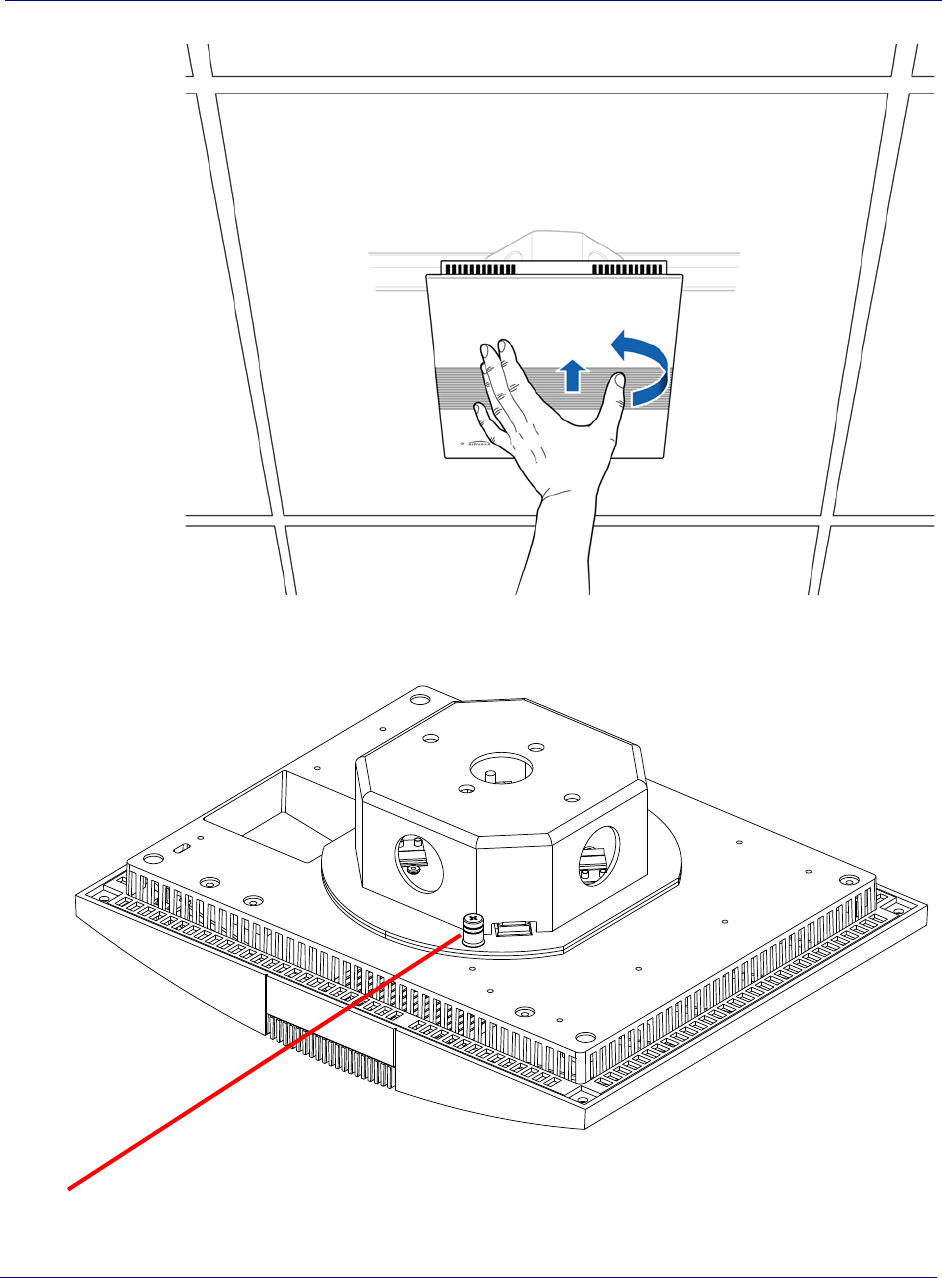
8Mount the Radio Point on the bracket.
Chapter 4 Radio Point Installation
4-891302010.05 April 2015
DRAFT
Tighten locking screw after installation of Radio Point
Chapter 4 Radio Point Installation
OneCell Installation and Commissioning, Release 1.0 4-9
DRAFT
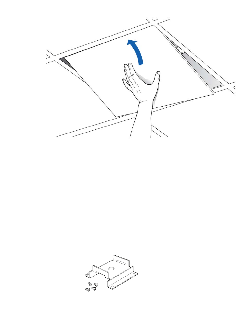
Mounting the Radio Point above the ceiling tile
1Remove ceiling tile from the overhead.
Chapter 4 Radio Point Installation
4-10 913020 10.05 April 2015
DRAFT
2Attach the bracket to the ceiling tile rail.
3Attach the octagon box to the bracket.
NOTE: Airvana recommends an Eaton B-line – BA50A adjustable bracket.
Chapter 4 Radio Point Installation
OneCell Installation and Commissioning, Release 1.0 4-11
DRAFT
4Attach the plate to the octagon box.
Chapter 4 Radio Point Installation
4-12 91302010.05 April 2015
DRAFT
5Attach plate to the Radio Point. Apply Thread locking compound to screws
prior to installation.
Chapter 4 Radio Point Installation
31-40.1 esaeleR ,gninoissimmoC dna noitallatsnI lleCenO
DRAFT
6Attach the Ethernet cable to the Radio Point.
Tighten locking screw after installation of Radio Point
Chapter 4 Radio Point Installation
4-14 913020 10.05 April 2015
DRAFT
7Attach the Radio Point to the plate.
NOTE: The minimum clearance for cooling is 4 inches.
8Replace the ceiling tile.
Ceiling tile
4”
Chapter 4 Radio Point Installation
OneCell Installation and Commissioning, Release 1.0 4-15
DRAFT
Flown mount
The Radio Point can be flown mounted on the end of a rod. This configuration is used
for building where there are no drop ceilings.
Mounting the Radio Point (RP) in the flown configuration requires the following
hardware provided by Airvana in the mounting kit:
• Mounting bracket
• Screws
Figure 4-4. Mounting bracket kit contents
Mounting the Radio Point (RP) in the flown configuration requires the following
hardware provided by the system integrator:
Chapter 4 Radio Point Installation
4-16 913020 10.05 April 2015
DRAFT
• Rod, 3/8-inch threaded
•Nut
• Lock nut, nylon
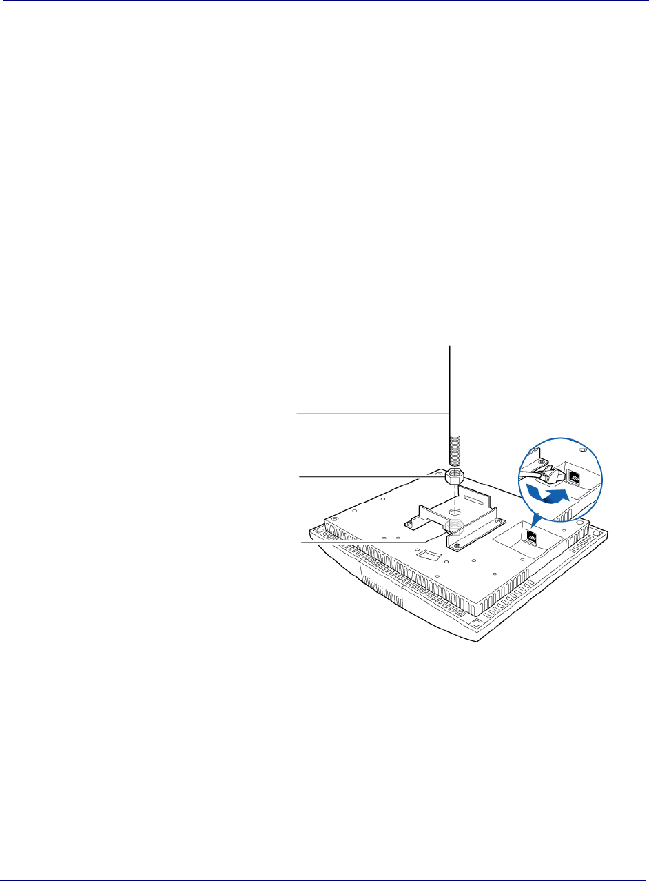
Flown mount installation
1Attach the threaded, 3/8-inch rod, cut to the required length, to the ceiling.
2Install the nut on the rod.
3Slide the bracket on the rod and install the nylon lock nut.
NOTE: Be sure the bracket is tight between the nuts and there is enough clearance
at the end of the rod to attach the bracket to the Radio Point.
4Attach the Airvana-supplied mounting bracket to the Radio Point.
5Connect the Ethernet cable to the Radio Point.
Pole mount
The Radio Point can be pole mounted. This configuration is used for building where
there are no drop ceilings.
3/8-inch rod
Nut
Nylon lock nut

Chapter 4 Radio Point Installation
OneCell Installation and Commissioning, Release 1.0 4-17
DRAFT
Mounting the Radio Point (RP) on a pole requires the following hardware provided by
Airvana in the mounting kit:
• Mounting bracket
• Screws
Figure 4-5. Mounting bracket kit contents
Mounting the Radio Point (RP) on a pole requires the following hardware provided by
the system integrator:
• Adjustable clamp at least 2 inches larger than the circumference of the pole
Chapter 4 Radio Point Installation
4-18 913020 10.05 April 2015
DRAFT
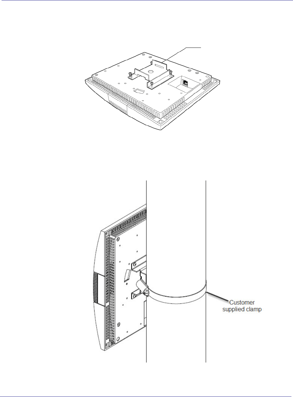
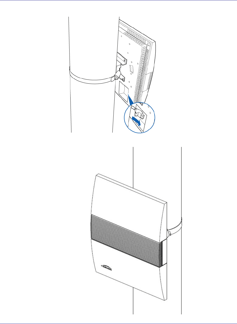
Pole mount installation
1Attach the bracket to the Radio point.
2Slide the adjustable clamp through the slots on the Radio Point bracket.
3Wrap the clamp around the pole and tighten the clamp screw to secure the Radio
Point to the pole.
4Connect the Ethernet cable to the Radio Point.
Mounting bracket
Chapter 4 Radio Point Installation
OneCell Installation and Commissioning, Release 1.0 4-19
DRAFT

Chapter 4 Radio Point Installation
4-20 913020 10.05 April 2015
DRAFT
DRAFT

1-A0.1 esaeleR ,gninoissimmoC dna noitallatsnI lleCenO
DRAFT
Appendix A
Safety
This appendix contains specifications for Airvana OneCell, including FCC
information and technical data.
2-AtnemetatS erusopxE noitaidaR CCF
2-Astnemyolped lleCenO rof stimil erusopxe namuH
4-A
t nemetatS erusopxE noitaidaR Canada

Appendix A Safety
A-2 913020 10.05 April 2015
DRAFT
FCC Radiation Exposure Statement
Important: Changes or modifications not expressly approved by Airvana LLC could
void your authority to operate the equipment.
This device complies with FCC’s RF radiation exposure limits set forth for an
uncontrolled environment under the following conditions:
• This device should be installed and operated such that a minimum separation
distance of 8 inches (20 cm) is maintained between the radiator (antenna) and the
user’s or nearby person’s body at all times.
• This transmitter must not be co-located or operating in conjunction with any other
antenna or transmitter.
For more information, see the publication femtocells and Health at
http:// www.femtoforum.org or visit the FCC website at www.fcc.gov.
FCC Part 15
This device has been tested and found to comply with the limits for a Class B digital
device, pursuant to Part 15 of the FCC Rules. These limits are designed to provide
reasonable protection against harmful interference in a residential installation. This
device generates, uses, and can radiate radio frequency energy and, if not installed and
used in accordance with the instructions, may cause harmful interference to radio
communications. However, there is no guarantee that interference will not occur in a
particular installation. If this device does cause harmful interference to radio or
television reception, which can be determined by turning the device off and on, the
user is encouraged to try to correct the interference by one of the following measures:
• Re-orient or relocate the receiving antennas of other devices.
• Increase the separation between the AIRAVE and other device receivers.
• Connect the AIRAVE into an outlet on a circuit different from that to which the
other device receiver is connected.
• Consult the dealer or an experienced radio/TV technician for help.
Human exposure limits for OneCell deployments
The human exposure limits for the OneCell product is calculated by using the
Maximum Permissible Exposure (MPE) method associated with fixed-type
transmitter devices.
Table A-1 includes values for one Radio Point (RP) and four Radio Points per chassis.

Appendix A Safety
OneCell Installation and Commissioning, Release 1.0 A-3
DRAFT
Reference documents
[1] Federal Communications Commission Document OET Bulletin 65, Supplement C,
2001, Evaluating Compliance with FCC guidelines for Human Exposure to radio
frequency Electromagnetic Fields, US Federal Communications Commission, Office
of Engineering and Technology June 2001.
[2] Federal Communications Commission Document OET Bulletin 56, “Questions
and answers about biological effects and potential hazards of radio frequency
electromagnetic fields”, Federal Communications Commission Office of Engineering
and Technology, August 1999.
[3] ICNIRP Guidelines for limiting exposure to time varying electric, magnetic and
electromagnetic fields up to 300 GHz. International Commission on Non Ionizing
Radiation, published in Health Physics 74 (4): 494-522; 1998
[4] ICNIRP Statement on EMF-Emitting New Technologies, International
Commission on Non-Ionizing Radiation, published in Health Physics 94 (4):376-392,
2008
[5] 3GPP Document 3GPP TS 36.104 version 10.11.0 Release 10,” LTE Evolved
Universal Terrestrial Radio Access (E-UTRA); Base Station (BS) radio transmission
and reception”
Table A-1. RF exposure for OneCell at maximum power internal antennas
Parameter Value for
One RP Value for
Two RPs
Tx Power (dBm) per antenna 23 23
Tx Loss (dB) 0 0
Tx Antenna Gain 2 4
Multi-operator Combiner Loss 0 – 6
Transmitter Duty Cycle % 100 100
Number of Antennas (MIMO) 2 2
Contribution due to multiple antennas (dB) 3.010299957 3.010299957
Power Increase due to multiple RPs (dB) 0 6.020599913
Derived Total EIRP (dBW) -1.989700043 0.03089987
Frequency (MHz) 1900 1900
Point Source Total EIRP (watts) 0.632455532 1.007140329
Target W/m^2 9.5 9.5

Appendix A Safety
A-4 91302010.05 April 2015
DRAFT
Canadian Compliance Statement
This device complies with Industry Canada license-exempt RSS standard(s). Operation is
subject to the following two conditions:
(1) This device may not cause interference, and
(2)This device must accept any interference, including interference that may cause undesired
operation of the device.
Cet appareil est conforme aux norms CNR exemptes de licence d’Industrie Canada. Le
fonctionnement est soumis aux deux conditions suivantes:
(1) cet appareil ne doit pas provoquer d’interférences et
(2) cet appareil doit accepter toute interférence, y compris celles susceptibles de provoquer un
fonctionnement non souhaité de l’appareil.
Industry Canada Statement
Complies with the Canadian ICES-003 Class B specifications.
Cet appareil numérique de la classe B est conforme à la norme NMB-003 du Canada.
This device complies with RSS 210 of Industry Canada. This Class B device meets all the
requirements of the Canadian interference-causing equipment regulations.
Cet appareil numérique de la Classe B respecte toutes les exigences du Règlement sur le
matériel brouilleur du Canada


Appendix B Specifications
B-2 913020 10.05 April 2015
DRAFT
Electrical ratings and technical data
The following table lists the electrical ratings and technical data for the Baseband
Controller Unit.
SPF/SPF+ specifications
The following table lists the SPF and SPF+ specifications required for the Baseband
Controller Unit.
Operating Environment 0 to 40°C, 10 to 90% relative humidity, indoor use only, not for wet
environments
Electrical Rating 100 - 230 AC, 2.0A, 50 - 60Hz (auto ranging, no adjustment
required)
Dimensions 19”w x 1.75”H x 18.8” D (483mm W x 44.4mm H x 477mm D)
Weight Single CU 13.1 lbs (5.9 KG), Dual CU 19.1 lbs. (8.7 KG)
Safety IEC 60950-1 2005 (Second edition) + A1:2009
1G SFP LC SX Transceiver; 220M to 1K M
1G SFP LC LX transceiver, 550M 10K M
10G SFP+ LC SR Transceiver; Multi mode 26M to 300M
10G SFP+ LC SR Transceiver; Single mode 10K M
10G Direct attach SFP+ cable; Twin ax Cable ; 7M (must be compatible with HP & Cisco
switches

OneCell Installation and Commissioning, Release 1.0 C-1
DRAFT
Appendix C
Installation troubleshooting
This section contains information on troubleshooting the OneCell installation. It
includes the LED patterns for the Baseband Controller and Radio points.
Controller LED patterns C-2
Radio Point LED patterns C-4

Appendix C Installation troubleshooting
C-2 913020 10.05 April 2015
DRAFT
Controller LED patterns
The Controller has four LEDs on the front panel. The following table shows
• Display pattern for each LED
• What the pattern indicates
• Action to take, if any, to resolve the issue
LED Display Pattern Indicates Action to Take
STATUS Green, solid Power On
Sectors up
None
Amber, solid Self-test failure
Green, blinking Firmware upgrade None
Amber, blinking Configuring from DMS
Red, solid Error in system - software or
hardware issues detected
RU ERROR Green, solid Power On None
Amber, solid Self-test failure
Amber, blinking No Radio Points connected
Off Radio Points connected,
firmware upgrade None
Red, blinking Radio Point alarm - PLL state
unlock; service impacting alarm
from Radio Point
TIMING LED Green, solid Power On, timing None
Amber, solid Self-test failure
Amber, blinking No timing
Off Firmware upgrade None
Red, solid Error

Appendix C Installation troubleshooting
OneCell Installation and Commissioning, Release 1.0 C-3
DRAFT
CORE LED Green, solid Power On
Connection to MME
None
Amber, solid Self-test failure
Amber, blinking No connection to MME
IPsec is up
Off Firmware upgrade None
Red, blinking Internet connection
IPsec down
Red solid No Internet
Interface hardware issues
LED Display Pattern Indicates Action to Take

Appendix C Installation troubleshooting
C-4 913020 10.05 April 2015
DRAFT
Radio Point LED patterns
The Radio Point has one LED on the front cover. The following table shows
• Display pattern for the LED
• What the pattern indicates
• Action to take, if any, to resolve the issue
LED Display Pattern Indicates Action to Take
STATUS Green, solid Power On
RFTx state is on
None
Amber, solid Self-test failure
Green, blinking Firmware upgrade
Connected to Controller
None
Amber, blinking PLL state – unlock
RFTx State – off or suspended
L2 path verification failed
AdminState – STANDBY
Red, blinking No connection to Controller
(http)
Red, solid Error in system – software or
hardware issues
Interface issues detected
AdminState – UNLOCKED

OneCell Installation and Commissioning, Release 1.0
Backcvr