CommScope Technologies S1000C CDMA 1X & EVDO,TD-LTE and Dual-Band Wi-Fi Small Cell User Manual S1000C UserGuide
CommScope Technologies LLC CDMA 1X & EVDO,TD-LTE and Dual-Band Wi-Fi Small Cell S1000C UserGuide
UserManual.wiki
>
CommScope Technologies
>
S1000C User Manual
UserGuide
Navigation menu
Upload a User Manual
Namespaces
Wiki Guide
HTML
PDF
Info
Views
User Manual
Discussion / Help
Navigation


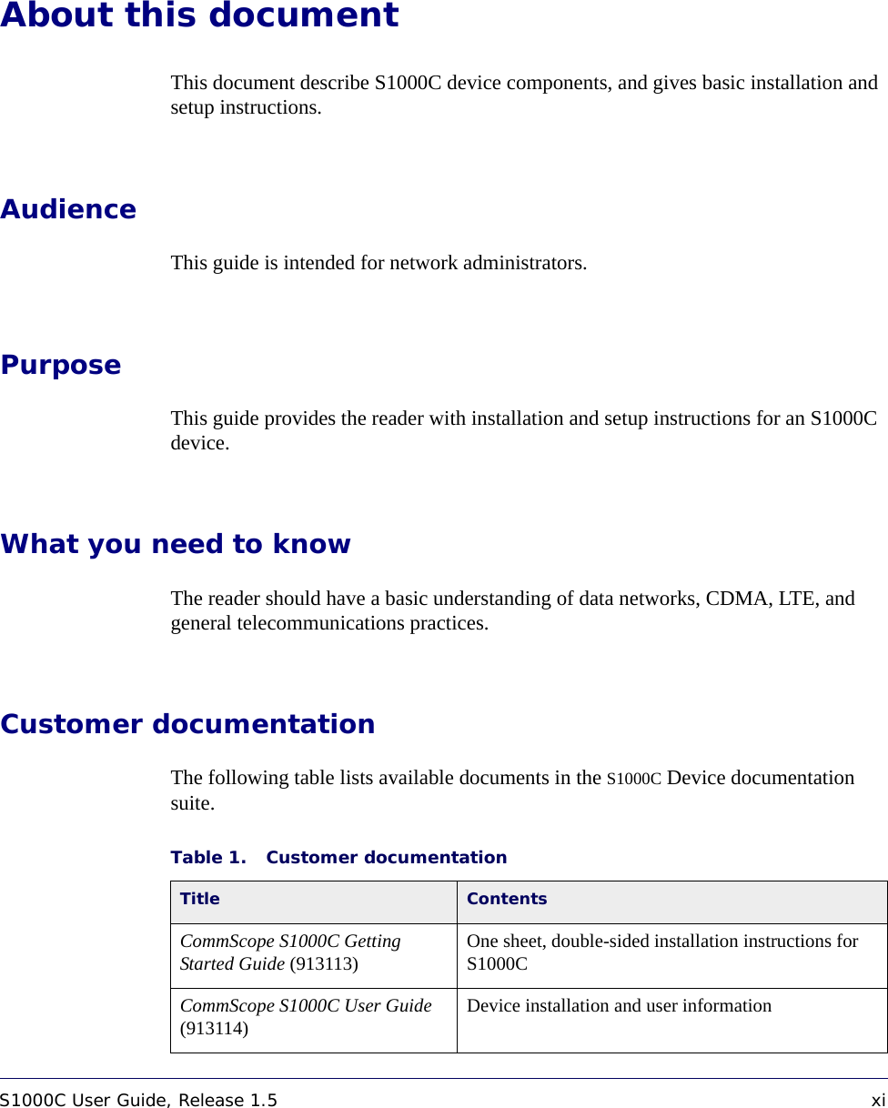
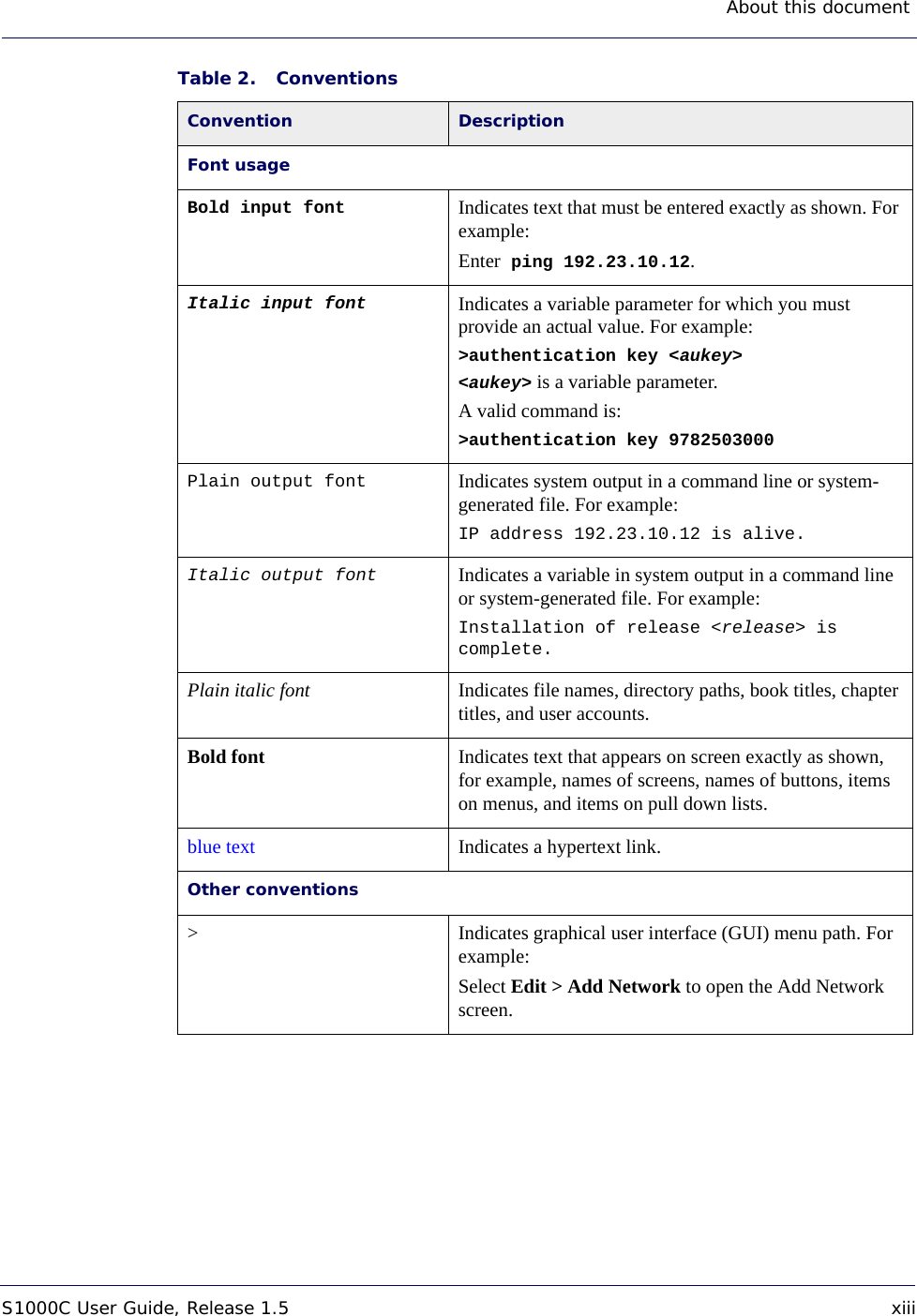
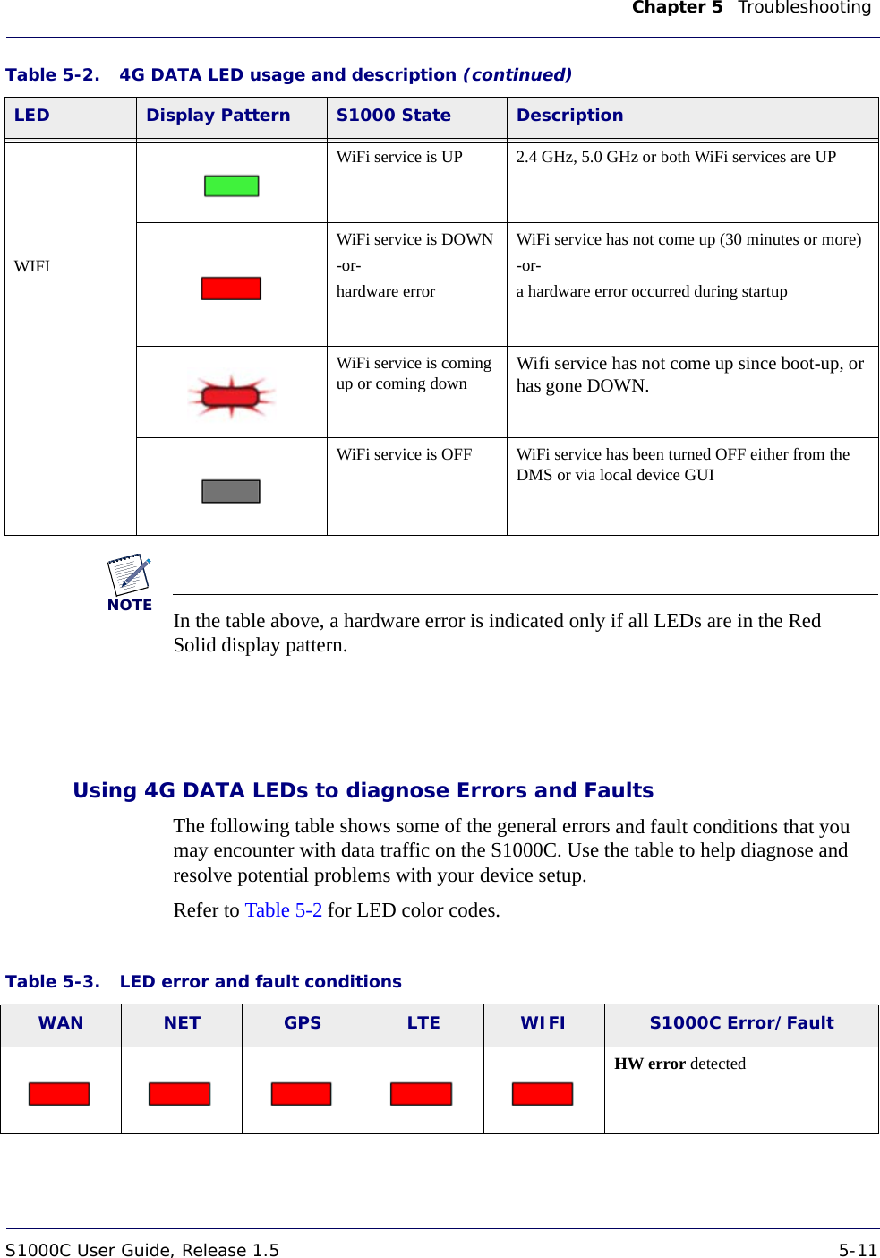
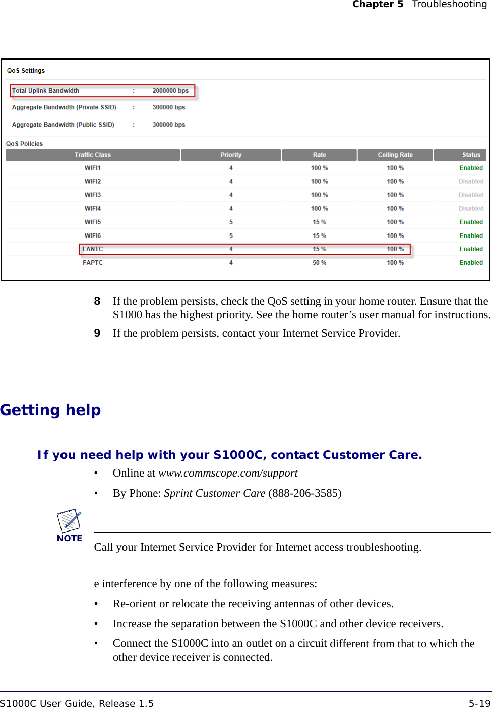
![About this document xii 913114 1.5.01 August 2016DRAFTConventionsThis guide uses the following text conventions, as applicable.Airvana Small Cell Deployment Guide (913111) Describes the DMS platform software upgrade procedures from the previous patch release to the current patch release and the DMS rollback and downgrade procedures from the current patch release to the previous patch release. Airvana S1000 Web GUI User Guide (913110) Describes the S1000 Web GUI and how to configure the S1000. Airvana S1000 Troubleshooting Guide (913112) Describes how to troubleshoot problems that customers may encounter with their S1000s.Table 1. Customer documentation Title ContentsTable 2. Conventions Convention DescriptionSyntax symbols< > Enclose a required parameter or set of parameters. For example:>band-class <class><class> is a required parameter.[ ] Enclose an optional parameter or set of parameters. For example:>activate image <version> [reboot][reboot] is an optional parameter. |Separates items on a list of parameters, only one of which can be used. For example:>channel-included <yes|no>A valid command is:>channel-included yes](https://usermanual.wiki/CommScope-Technologies/S1000C/User-Guide-3157712-Page-12.png)