CommScope Technologies S1000C CDMA 1X & EVDO,TD-LTE and Dual-Band Wi-Fi Small Cell User Manual S1000C UserGuide
CommScope Technologies LLC CDMA 1X & EVDO,TD-LTE and Dual-Band Wi-Fi Small Cell S1000C UserGuide
UserGuide
DRAFT
User Guide
Release 1.5
Document Number: 913114
Document Revision: 1.5.01
Date: August 2016
S1000C

ii 913114 1.5.01 August 2016
DRAFT
Copyright 2016 CommScope, All rights reserved.
THIS DOCUMENT HAS BEEN DEVELOPED BY COMMSCOPE, AND IS INTENDED FOR THE USE OF ITS
CUSTOMERS AND CUSTOMER SUPPORT PERSONNEL.
THE SPECIFICATIONS AND INFORMATION REGARDING THE PRODUCTS IN THIS MANUAL ARE SUBJECT
TO CHANGE WITHOUT NOTICE. ALL STATEMENTS, INFORMATION, AND RECOMMENDATIONS IN THIS
MANUAL ARE BELIEVED TO BE ACCURATE BUT ARE PRESENTED WITHOUT WARRANTY OF ANY KIND,
EXPRESS OR IMPLIED. USERS MUST TAKE FULL RESPONSIBILITY FOR THEIR APPLICATION OF ANY
PRODUCTS.
THE SOFTWARE LICENSE AND LIMITED WARRANTY FOR THE ACCOMPANYING PRODUCT ARE SET
FORTH IN THE INFORMATION PACKET THAT SHIPPED WITH THE PRODUCT AND ARE INCORPORATED
HEREIN BY REFERENCE. IF YOU ARE UNABLE TO LOCATE THE SOFTWARE LICENSE OR LIMITED
WARRANTY, CONTACT YOUR COMMSCOPE SALES REPRESENTATIVE FOR A COPY.

S1000C User Guide, Release 1.5 iii
DRAFT
Contents
Audience ......................................................................................................................xi
Purpose.........................................................................................................................xi
What you need to know ...............................................................................................xi
Customer documentation .............................................................................................xi
Conventions ................................................................................................................xii
Notes, cautions, and warnings ...................................................................................xiv
Chapter 1
Introduction
Using this guide...................................................................................................1-1
Chapter 2
Getting Started
What’s in the box .......................................................................................................2-2
Setup at a glance ........................................................................................................2-3
Setting up your S1000C.............................................................................................2-4
When is your S1000C ready to use?..........................................................................2-7
4G DATA LEDs ..................................................................................................2-7
Setting up optional components.................................................................................2-9
External GPS antenna setup ................................................................................2-9
PC or LAN Router Setup...................................................................................2-11
Chapter 3
Configuring the S1000C Router
Overview....................................................................................................................3-1
Logging in to the S1000C router ...............................................................................3-3
Home page...........................................................................................................3-4
Configuring WiFi service...........................................................................................3-5
Basic Settings......................................................................................................3-5
Multiple SSID Setup ...........................................................................................3-7
SSID IP configuration .......................................................................................3-10
Advanced Settings.............................................................................................3-11
MAC Address Filtering.....................................................................................3-12
Adding your ISP User Name and Password ............................................................3-14
Chapter 4
Using the S1000C
How the S1000C works .............................................................................................4-1
Discovery and data exchange..............................................................................4-2

Contents
iv 913114 1.5.01 August 2016
DRAFT
How data goes over the Internet ................................................................................4-4
Using the External GPS Antenna...............................................................................4-5
Maintenance...............................................................................................................4-6
Chapter 5
Troubleshooting
Troubleshooting installation problems.......................................................................5-1
Resetting the S1000C.................................................................................................5-3
LED quick reference..................................................................................................5-4
4G DATA LEDs ..................................................................................................5-5
3G VOICE LEDs.................................................................................................5-6
Router connection problems ......................................................................................5-7
Common connection types..................................................................................5-7
Using LEDs................................................................................................................5-9
4G DATA LEDs ..................................................................................................5-9
Using 4G DATA LEDs to diagnose Errors and Faults......................................5-11
3G VOICE LEDs...............................................................................................5-13
FAQs ........................................................................................................................5-16
Why does the S1000C need a GPS antenna? ....................................................5-16
Why does the S1000C need an external GPS antenna? ....................................5-16
What should I do if the GPS fails to acquire a lock? ........................................5-16
What happens to the S1000C if there is a power outage or if you lose Internet
access?...............................................................................................................5-16
Can you move the S1000C to another location?...............................................5-16
I have a DSL modem and cannot connect to the Internet .................................5-17
My calls work fine outside but drop indoors.....................................................5-17
My Internet connection is slow when my laptop is connected to the S1000C..5-17
Getting help..............................................................................................................5-19
Chapter 6
Safety information
General precautions ...................................................................................................6-1
FCC information........................................................................................................6-2
! FCC radiation exposure statement....................................................................6-2
FCC Part 15.........................................................................................................6-2

Contents
S1000C User Guide, Release 1.5 v
DRAFT

List of figures
vi 913114 1.5.01 August 2016
DRAFT
List of figures
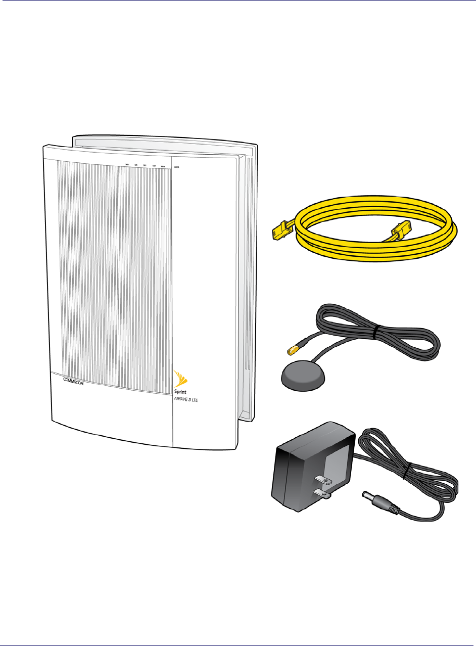
Figure 2-1 Box contents ....................................................................................2-2
Figure 2-2 Setup at a glance..............................................................................2-3
Figure 2-3 S1000C location in a building .........................................................2-4
Figure 2-4 WAN port connection......................................................................2-5
Figure 2-5 Power supply connection.................................................................2-6
Figure 2-6 External GPS antenna connection .................................................2-10
Figure 2-7 PC or LAN router setup.................................................................2-11
Figure 3-1 Basic Settings page..........................................................................3-5
Figure 3-2 Multiple SSID Setup page ...............................................................3-7
Figure 3-3 Edit SSID Details page....................................................................3-8
Figure 3-4 LAN IP Setup page........................................................................3-10
Figure 3-5 Advanced Settings page.................................................................3-11
Figure 3-6 MAC Address Filtering page.........................................................3-13
Figure 4-1 S1000C internal view ......................................................................4-3
Figure 4-2 How data goes over the Internet......................................................4-4
Figure 5-1 Resetting the S1000C ......................................................................5-3
Figure 5-2 S1000C LED layout.........................................................................5-4

List of tables
S1000C User Guide, Release 1.5 vii
DRAFT
List of tables
Table 1 Customer documentation .....................................................................xi
Table 2 Conventions ........................................................................................xii
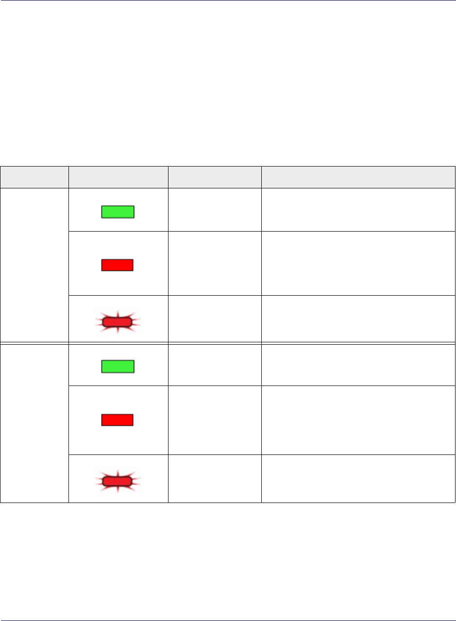
Table 1-1 4G DATA LED color key..................................................................1-2
Table 2-1 4G Data LED states during S1000C boot sequence...........................2-7
Table 3-1 Basic Settings parameters...................................................................3-5
Table 3-2 Mode, bandwidth and data rate configurations ..................................3-6
Table 3-3 Multiple SSID List parameters...........................................................3-7
Table 3-4 Edit SSID Details parameters.............................................................3-9
Table 3-5 LAN IP Setup parameters ................................................................3-10
Table 3-6 Advanced Settings parameters .........................................................3-12
Table 3-7 MAC Address Filtering parameters .................................................3-13
Table 5-1 Common connection types.................................................................5-7
Table 5-2 4G DATA LED usage and description ..............................................5-9
Table 5-3 LED error and fault conditions.........................................................5-11
Table 5-4 3G VOICE LED display patterns and actions..................................5-13

List of tables
viii 913114 1.5.01 August 2016
DRAFT

S1000C User Guide, Release 1.5 ix
DRAFT
New in this release
The following section lists documentation changes in CommScope S1000C User
Guide (913114) for Release 1.5.
Revision 1.5.01
• Initial release of document

New in this release
x913114 1.5.01 August 2016
DRAFT

S1000C User Guide, Release 1.5 xi
DRAFT
About this document
This document describe S1000C device components, and gives basic installation and
setup instructions.
Audience
This guide is intended for network administrators.
Purpose
This guide provides the reader with installation and setup instructions for an S1000C
device.
What you need to know
The reader should have a basic understanding of data networks, CDMA, LTE, and
general telecommunications practices.
Customer documentation
The following table lists available documents in the S1000C Device documentation
suite.
Table 1. Customer documentation
Title Contents
CommScope S1000C Getting
Started Guide (913113) One sheet, double-sided installation instructions for
S1000C
CommScope S1000C User Guide
(913114) Device installation and user information
About this document
xii 913114 1.5.01 August 2016
DRAFT
Conventions
This guide uses the following text conventions, as applicable.
Airvana Small Cell Deployment
Guide (913111) Describes the DMS platform software upgrade
procedures from the previous patch release to the
current patch release and the DMS rollback and
downgrade procedures from the current patch release
to the previous patch release.
Airvana S1000 Web GUI User
Guide (913110) Describes the S1000 Web GUI and how to configure
the S1000.
Airvana S1000 Troubleshooting
Guide (913112) Describes how to troubleshoot problems that
customers may encounter with their S1000s.
Table 1. Customer documentation
Title Contents
Table 2. Conventions
Convention Description
Syntax symbols
< > Enclose a required parameter or set of parameters. For
example:
>band-class <class>
<class> is a required parameter.
[ ] Enclose an optional parameter or set of parameters. For
example:
>activate image <version> [reboot]
[reboot] is an optional parameter.
|Separates items on a list of parameters, only one of
which can be used. For example:
>channel-included <yes|no>
A valid command is:
>channel-included yes

About this document
S1000C User Guide, Release 1.5 xiii
DRAFT
Font usage
Bold input font Indicates text that must be entered exactly as shown. For
example:
Enter ping 192.23.10.12.
Italic input font Indicates a variable parameter for which you must
provide an actual value. For example:
>authentication key <aukey>
<aukey> is a variable parameter.
A valid command is:
>authentication key 9782503000
Plain output font Indicates system output in a command line or system-
generated file. For example:
IP address 192.23.10.12 is alive.
Italic output font Indicates a variable in system output in a command line
or system-generated file. For example:
Installation of release <release> is
complete.
Plain italic font Indicates file names, directory paths, book titles, chapter
titles, and user accounts.
Bold font Indicates text that appears on screen exactly as shown,
for example, names of screens, names of buttons, items
on menus, and items on pull down lists.
blue text Indicates a hypertext link.
Other conventions
>Indicates graphical user interface (GUI) menu path. For
example:
Select Edit > Add Network to open the Add Network
screen.
Table 2. Conventions
Convention Description
About this document
xiv 913114 1.5.01 August 2016
DRAFT
Notes, cautions, and warnings
NOTE
Notes provide additional information about the subject text.
CAUTION
Cautions indicate that procedures, if performed incorrectly, can cause equipment
damage or data loss.
WARNING
Warnings indicate that procedures, if performed incorrectly, can harm you.

S1000C User Guide, Release 1.5 1-1
DRAFT
Chapter 1
Introduction
The S1000C 3G+4G Small Cell Device is an indoor small cell intended for use by
small to medium size businesses. The device contains an S1000 coupled with the
CDMA FAP in a single enclosure. The combination of the S1000 and cFAP allows
both data and voice capability in a single offering.
The S1000C offers any-to-any mobility through LTE technology, offering users
seamless mobility between indoor and outdoor coverage. It also offers dual-
concurrent 2.4/5 GHz 802.11ac WiFi to deliver high data rates and performance.
The WiFi capabilities include automatic channel selection and Interference avoidance,
and Band steering to 5GHz for supporting devices. Up to 12 SSIDs are supported with
transparent authentication of public SSIDs using the 802.1x protocol.
Circuit Switched Fallback (CSFB) enables circuit switched voice and SMS services to
be delivered to dual radio Long Term Evolution (LTE) component of the S1000C, then
switched to the 3G network running on the internal cFAP. In this release, the cFAP
used is the C4500 (CDMA).
Using this guide
This user guide introduces you to the services and features of the CommScope
S1000C. The guide is divided into the following chapters:
•Getting Started on page 2-1
•Configuring the S1000C Router on page 3-1
•Using the S1000C on page 4-1
•Troubleshooting on page 5-1
•Safety information on page 6-1
It is important that you read each section and note any special requirements before you
use the device.
Chapter 1 Introduction
1-2 913114 1.5.01 August 2016
DRAFT
WARNING
Please read the Safety information on page 6-1 to learn about how to safely use
your device. Failure to read and follow the safety information in this user guide
may result in serious bodily injury, death, or property damage.
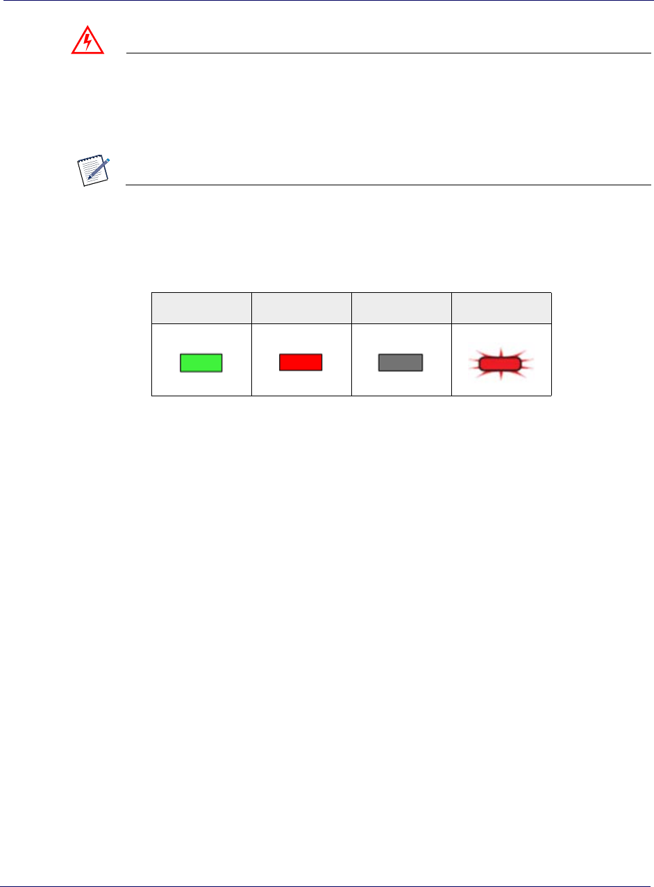
NOTE
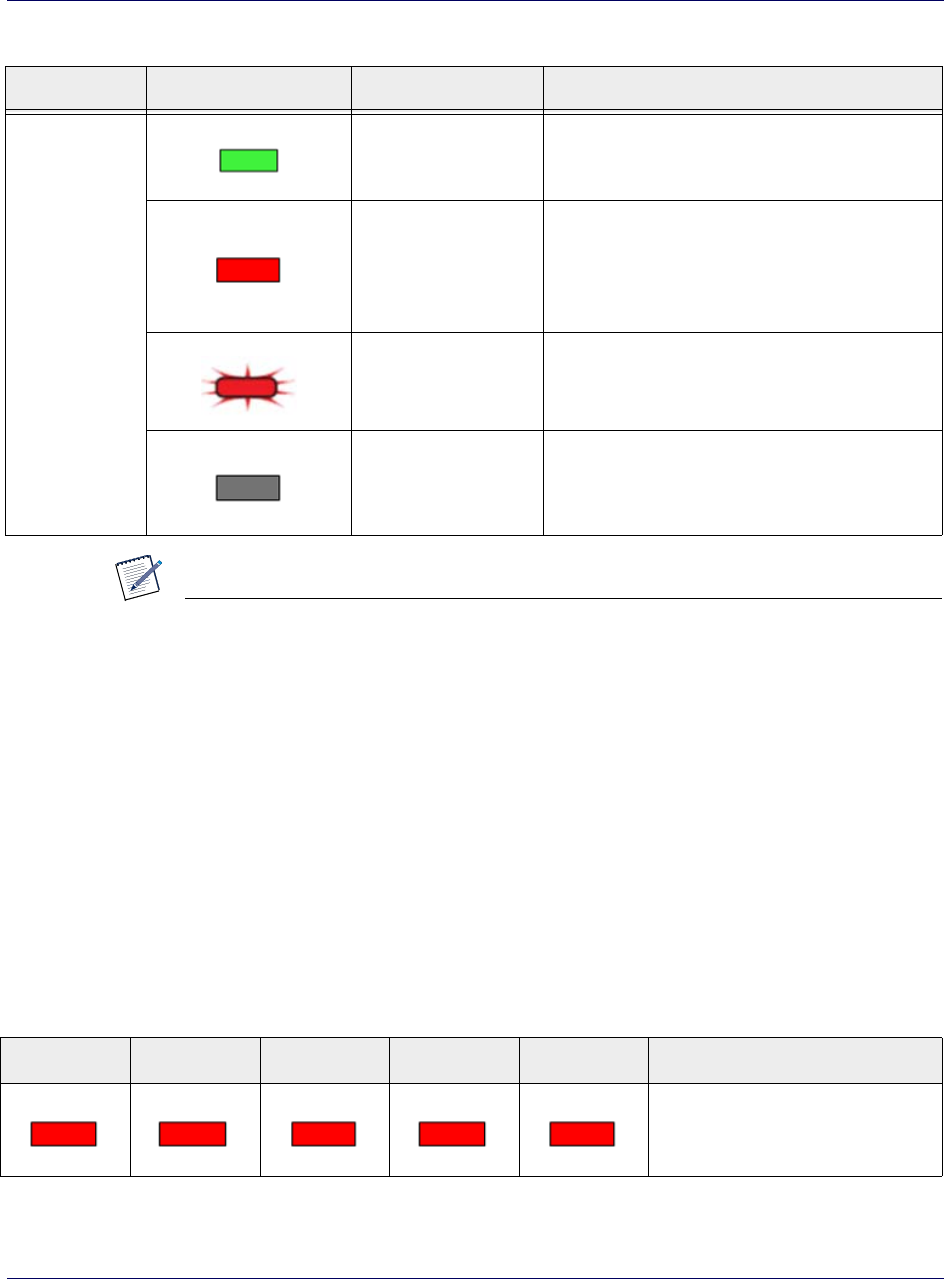
Use the following key when viewing 4G DATA LED tables in this document:
Table 1-1. 4G DATA LED color key
Solid Green Solid Red Off Blinking Red

S1000C User Guide, Release 1.5 2-1
DRAFT
Chapter 2
Getting Started
This chapter describes the contents of the S1000C box and setting up your S1000C.
•What’s in the box on page 2-2
•Setup at a glance on page 2-3
•Setting up your S1000C on page 2-4
•Setting up optional components on page 2-9
NOTE
When you complete this chapter, configure WiFi and other services of the internal
router in Chapter 3, Configuring the S1000C Router.
Chapter 2 Getting Started
2-2 913114 1.5.01 August 2016
DRAFT
What’s in the box
Ensure that the following items are in the box, along with the Quick Start Guide.
Figure 2-1.
S1000C 3G+4G Small Cell Device
External GPS Cable
Ethernet Cable
Power Supply
Box contents
Chapter 2 Getting Started
S1000C User Guide, Release 1.5 2-3
DRAFT
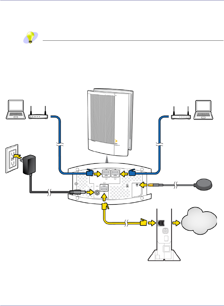
Setup at a glance
The following diagram shows a typical S1000C desktop setup.
TIP
Place the unit on it’s side on a flat surface to expose the bottom of the unit. You
will attach cables to the bottom of the unit.
Figure 2-2.
PC or LAN Router
(optional) PC or LAN Router
(optional)
To
Internet
Power
Supply
IMPORTANT: To ensure the best service quality,
always connect your S1000C directly to the
broadband connection device.
Broadband Connection
Device
External GPS Antenna
(if needed)
S1000C
Setup at a glance
Chapter 2 Getting Started
2-4 913114 1.5.01 August 2016
DRAFT
Setting up your S1000C
Follow these steps to set up your S1000C inside your office or other location.
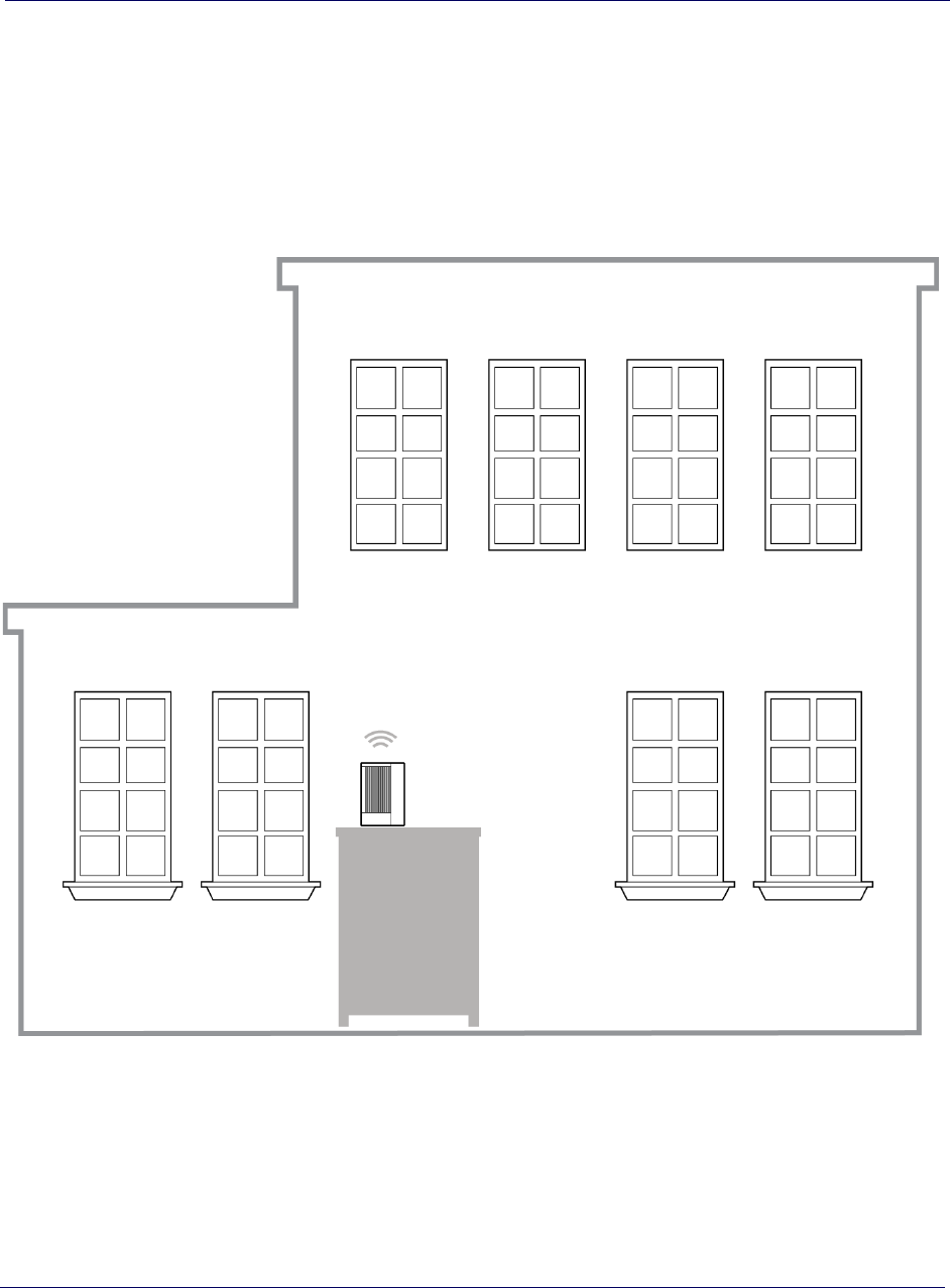
Figure 2-3. S1000C location in a building
Close to
Window
S1000C
Elevated
Location
1Disconnect the power from all devices on your network.
2Place your S1000C in a central location. For best results, place the S1000 in an
elevated location, such as the top of a bookshelf or tall cabinet.
3Place the unit on it’s side to expose the bottom of the unit.
Chapter 2 Getting Started
S1000C User Guide, Release 1.5 2-5
DRAFT
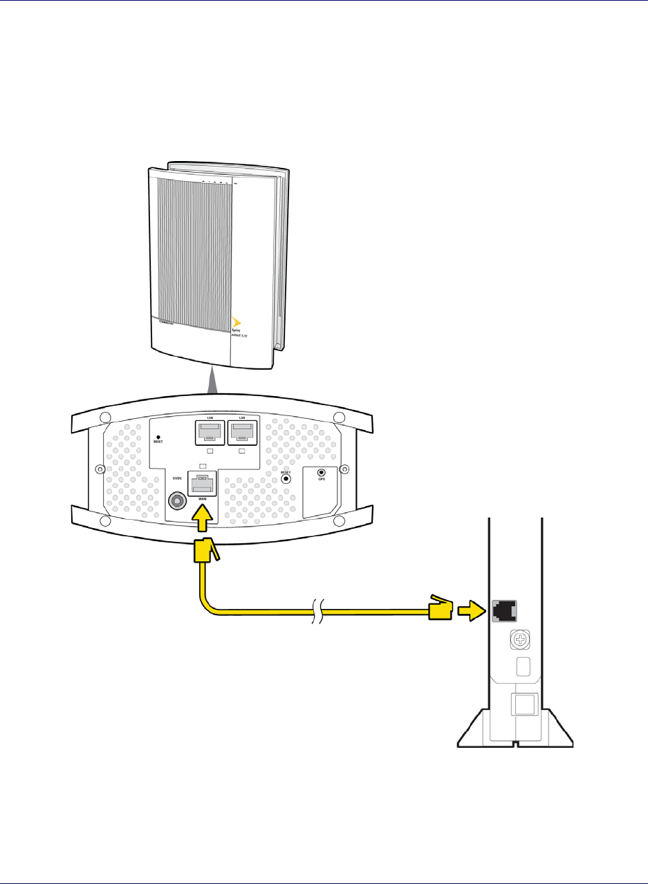
4Connect one end of the yellow Ethernet cable to an available LAN port on your
broadband connection device.
5Connect the other end of the yellow Ethernet cable to your S1000C’s WAN port.
Figure 2-4. WAN port connection
S1000C
Broadband Connection
Device
WAN Port
To LAN Port
6Turn on your broadband connection device.
Chapter 2 Getting Started
2-6 913114 1.5.01 August 2016
DRAFT
NOTE
Wait a couple of minutes for the broadband device to fully initialize before
continuing.
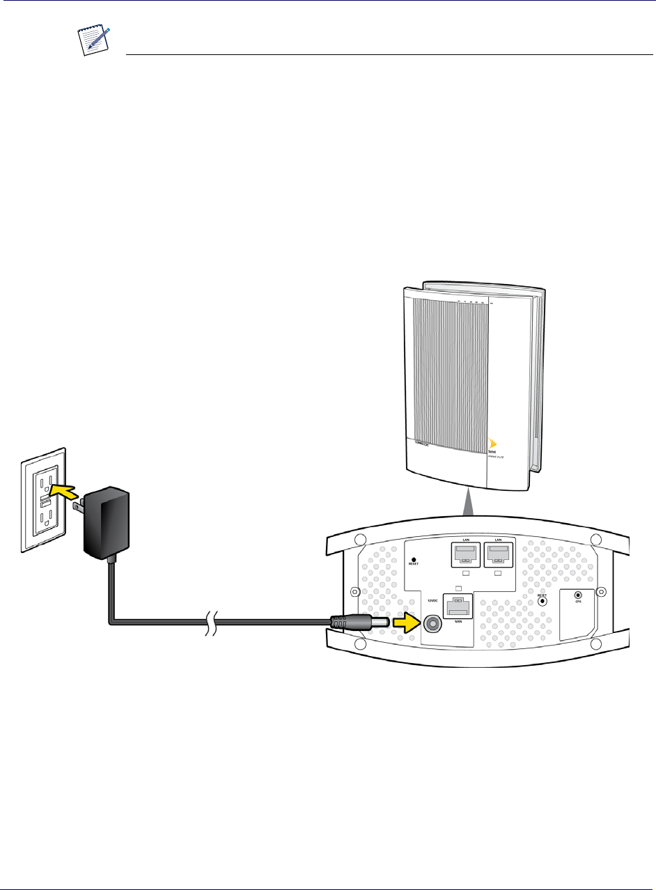
7Plug the power supply connector into the black power port on your S1000C.
Figure 2-5. Power supply connection
Power
Supply
S1000C
8Stand the unit upright and carefully move all cables so they come out of one long
end of the unit.
NOTE: There is room for cables to come out from the beneath the unit once it is
placed upright.
9Plug the other end of the power cable into an available electrical outlet. (We
recommend a surge protected outlet.)

Chapter 2 Getting Started
S1000C User Guide, Release 1.5 2-7
DRAFT
When is your S1000C ready to use?
When you install and power on your S1000C for the first time, it will go through an
automated setup sequence.
The side of the device marked 'DATA' displays LEDs for 4G LTE data passing
through the device. The side of the device labeled 'VOICE' displays LEDs for 3G
voice signals.
NOTE
Data LEDs and Voice LEDS must be solid green before the S1000C is ready for
data and voice traffic.
4G DATA LEDs
Table 2-1 shows the S1000C LED states on the DATA side during normal boot-up.
Refer to Table 1-1 for LED color codes.
Table 2-1. 4G Data LED states during S1000C boot sequence
WAN NET GPS LTE WiFi S1000C State
Performing initial HW tests (1-2
seconds)
HW tests are complete; software
is loading.
Software is loaded; services are
initializing.
WAN port is connected over the
local network; IPSec tunnel is not
established.
WAN port is connected; IPSec
tunnel is established and UP.
WAN port is connected; IPSec
tunnel is established and UP; GPS
Time Fix is available; LTE
service is UP.
Chapter 2 Getting Started
2-8 913114 1.5.01 August 2016
DRAFT
During boot-up the device’s green LED will be solid for a few seconds during initial
hardware tests. Upon completion of hardware tests, all LEDs, except the WAN LED,
will turn off until the software loads. This takes 1 to 2 seconds.
When the WAN, NET, GPS, LTE, and WIFI LEDs are solid green, your S1000C is
ready for data traffic.
NOTE
On the 3G side, the LEDs will change color during the automated setup sequence.
This process may take up to 2 hours. When the CDMA, NET, GPS, and WAN
LEDs are solid green, your S1000C is ready for voice traffic.
NOTE
For a summary of LED status indicators, see LED quick reference on page 5-4. For
a complete description of LED states, see Using LEDs on page 5-9.
WAN port is connected; IPSec
tunnel established and UP; GPS
Time Fix is available; LTE
service is UP; WiFi service is UP.
Table 2-1. 4G Data LED states during S1000C boot sequence (continued)
WAN NET GPS LTE WiFi S1000C State

Chapter 2 Getting Started
S1000C User Guide, Release 1.5 2-9
DRAFT
Setting up optional components
In this section:
•External GPS antenna setup on page 2-9
•PC or LAN Router Setup on page 2-11
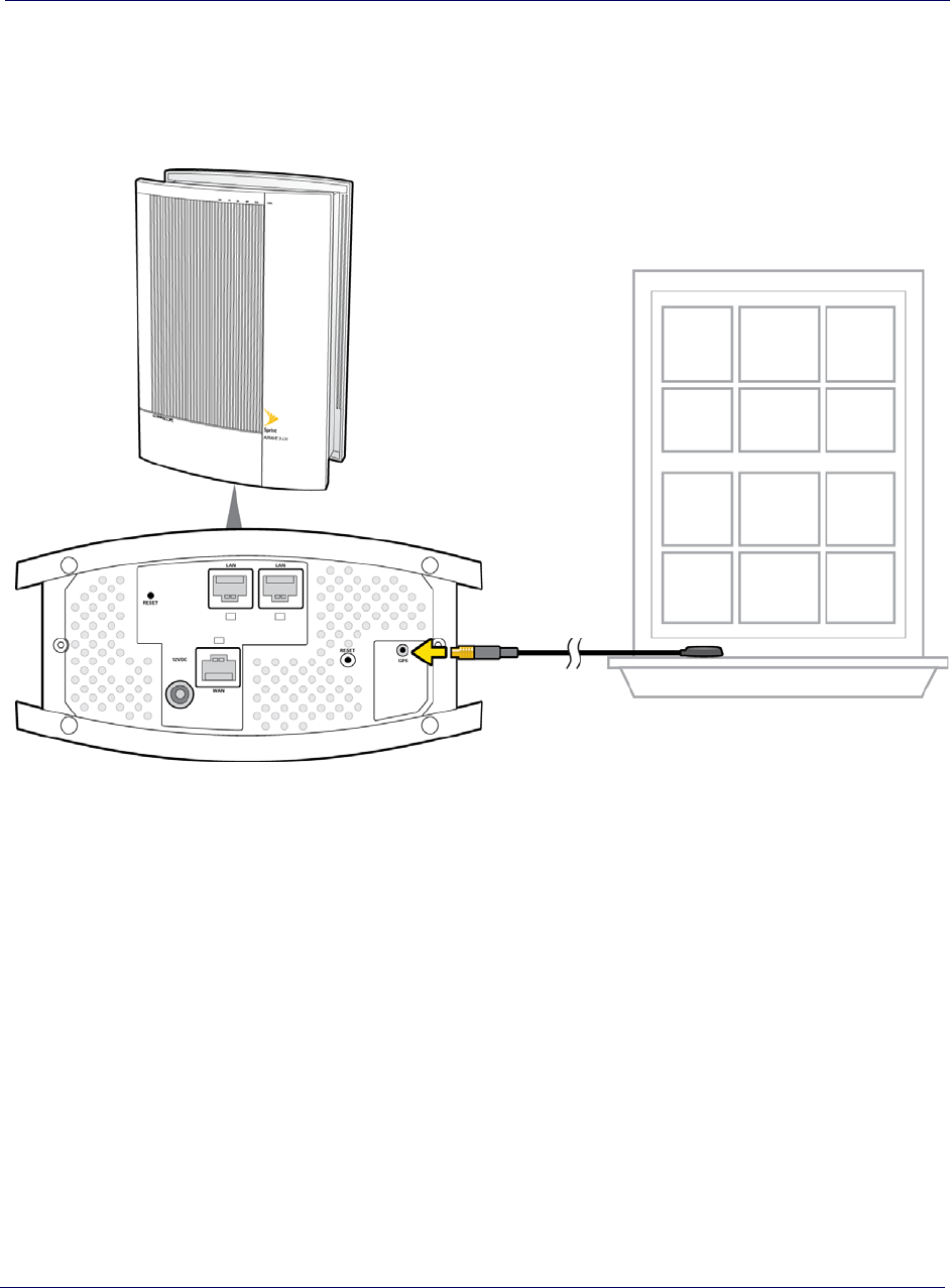
External GPS antenna setup
Use the external GPS antenna if the internal antenna of your S1000C does not gain a
signal for GPS lock (indicated by a solid red GPS LED for more than 2 hours, solid
green indicates GPS lock). Connect the external GPS antenna to your device's GPS
connection port.
NOTE
After initial installation, GPS may take 30-40 minutes to get a GPS fix.
1Place the external GPS antenna horizontally on a flat surface as close to a window
as possible. The antenna works best in an open area where it can easily pick up
signals.
2Place the S1000C on it’s side to expose the bottom of the unit.
3Plug the GPS cable into the GPS port on the bottom of the unit as shown in the
following diagram.
4Stand the unit upright and gently pull the cables to the one of the long sides of the
unit.
Chapter 2 Getting Started
2-10 913114 1.5.01 August 2016
DRAFT
This diagram shows the proper placement of the external GPS antenna.
Figure 2-6.
NOTE: Place the external GPS
antenna on a flat surface near a
closed window.
S1000C
GPS Port
External GPS antenna connection
Chapter 2 Getting Started
S1000C User Guide, Release 1.5 2-11
DRAFT
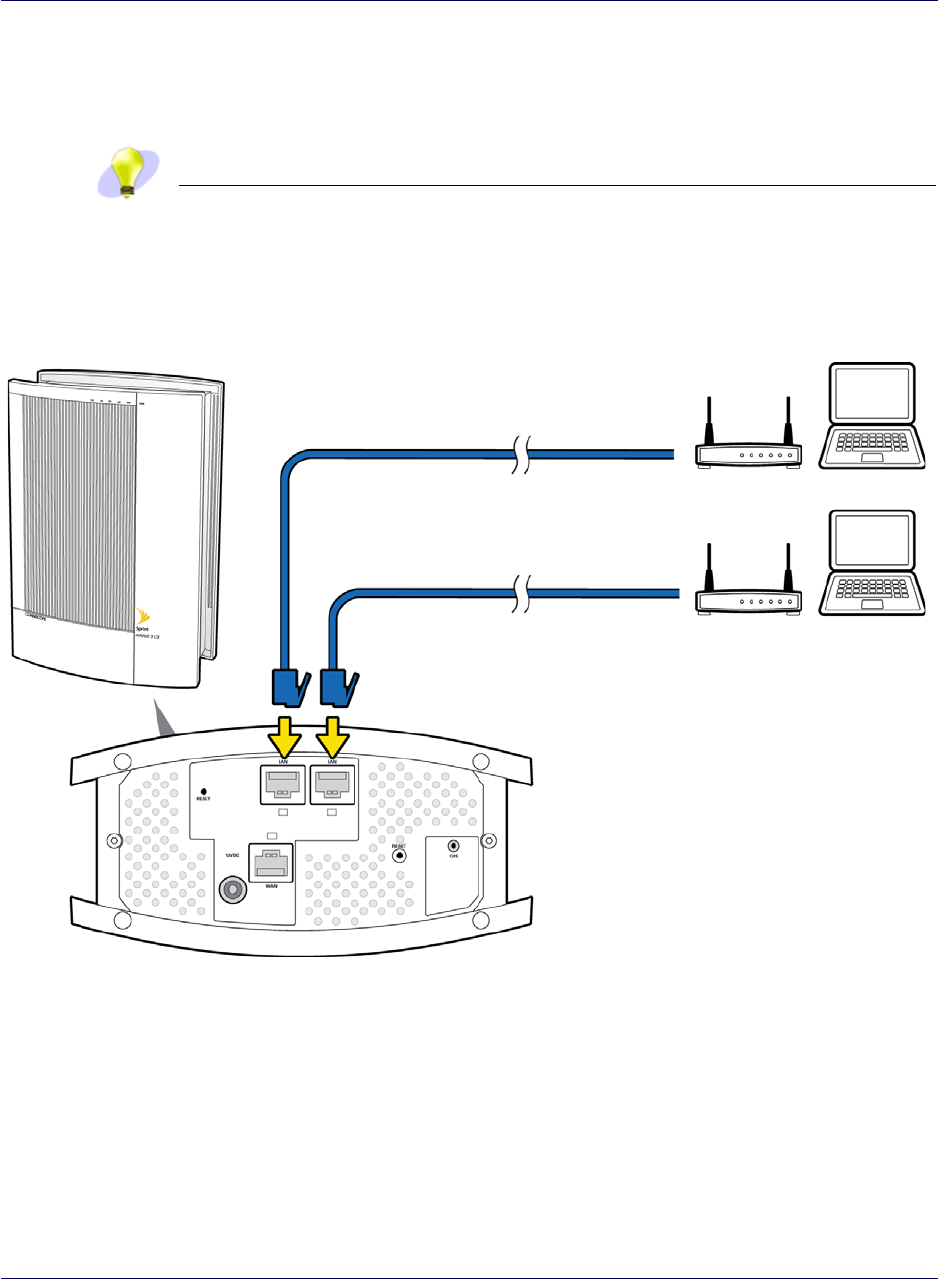
PC or LAN Router Setup
Connect a device that you have, such as a PC or a LAN router, to one of the S1000C's
LAN ports.
TIP
To ensure the best service quality, always connect the LAN router to your S1000C.
Do not connect it to the broadband connection device.
Figure 2-7.
To PC or LAN Router
LAN Ports
S1000C
PC or LAN router setup

Chapter 2 Getting Started
2-12 913114 1.5.01 August 2016
DRAFT

S1000C User Guide, Release 1.5 3-1
DRAFT
Chapter 3
Configuring the S1000C Router
This chapter describes how to configure the internal router:
•Overview on page 3-1
•Logging in to the S1000C router on page 3-3
•Configuring WiFi service on page 3-5
•Adding your ISP User Name and Password on page 3-14
Overview
Your S1000C contains a built-in router. Usually, you can plug your S1000C into your
broadband connection device, such as a cable modem, DSL modem or FIOS (a high-
speed, fiber optic broadband Internet service), without performing any additional
steps. However, you may need to configure the built-in router to work with your ISP
modem or connection device.
The following table lists typical ISP setups and actions to take so that the built-in
router works with your existing ISP setup.
For a complete description of the S1000C router configuration, refer to Airvana S1000
Web GUI User Guide (913110).
Broadband
connection device LED display
pattern Symptom Action to take
Cable modem WAN, LTE and WiFi solid
green Not applicable (working
properly) Not applicable
DSL modem WAN LED blinking red Cannot access Internet Go to Adding your ISP
User Name and Password

Chapter 3 Configuring the S1000C Router
3-2 913114 1.5.01 August 2016
DRAFT
DSL modem with built-in
router WAN led blinking red Cannot access Internet See FAQs.
If the problem persists,
contact Customer Support
as described in Getting
help.
DSL modem WIFI LED blinking red Cannot access Internet Go to Configuring WiFi
service
Broadband
connection device LED display
pattern Symptom Action to take
Chapter 3 Configuring the S1000C Router
S1000C User Guide, Release 1.5 3-3
DRAFT
Logging in to the S1000C router
1Connect a computer to the S1000C LAN ports.
2Start the computer. (If it is already running, restart it.)
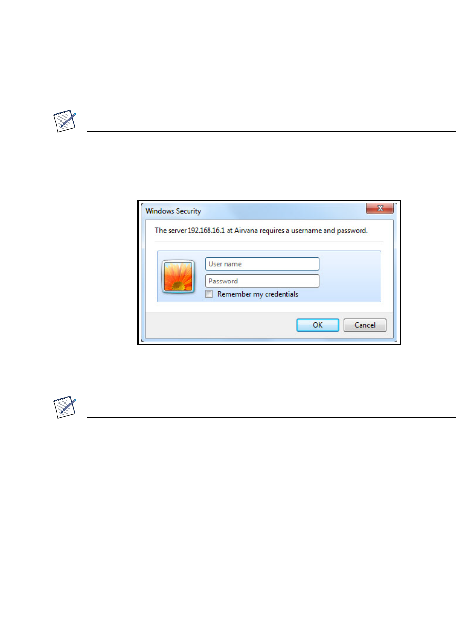
3In a web browser, enter the following URL:
http://192.168.16.1
NOTE
This IP address is the LAN bridge IP address.
The login dialog box appears.
4Enter the User name admin and the Password admin.
5Click OK.
NOTE
If you cannot connect to the router, diagnose the problem using the steps in section
Router connection problems on page 5-7.
Chapter 3 Configuring the S1000C Router
3-4 913114 1.5.01 August 2016
DRAFT
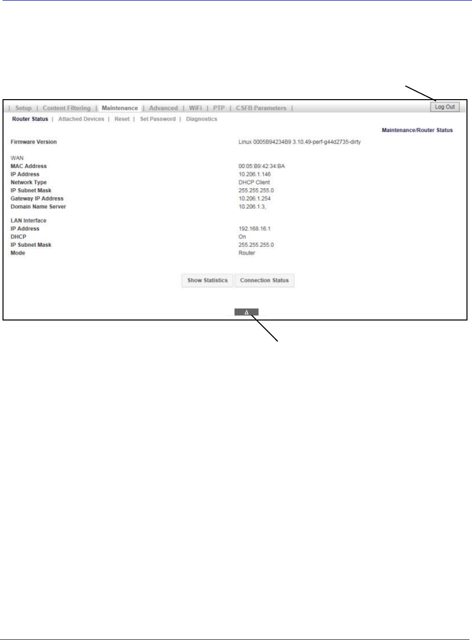
Home page
When connected to the router, the Router Status screen appears as shown below.
Help button
Log Out button
Main menu
The main menu, on the top of the screen, contains a menu bar to access the major
screens.
The main menu also contains the following buttons:
•Log Out – When finished, click this button to log out.
•Help – Located at the bottom of the screen, click to view help for the current
screen.
Navigation and data input
Use the menu bar on the top of the screen and the browser’s Back button to navigate.
You must click Save before changing screens or the software does not save changes.
In order to use WiFi features of the S1000C, you need to configure WiFi service.
Proceed to Configuring WiFi service.
Chapter 3 Configuring the S1000C Router
S1000C User Guide, Release 1.5 3-5
DRAFT
Configuring WiFi service
Follow this section to setup the S1000C’s WiFi service. You will create and configure
SSIDs in the router.
1Log into the S1000C router by following the procedure in Logging in to the
S1000C router.
2From the Home page click WiFi.
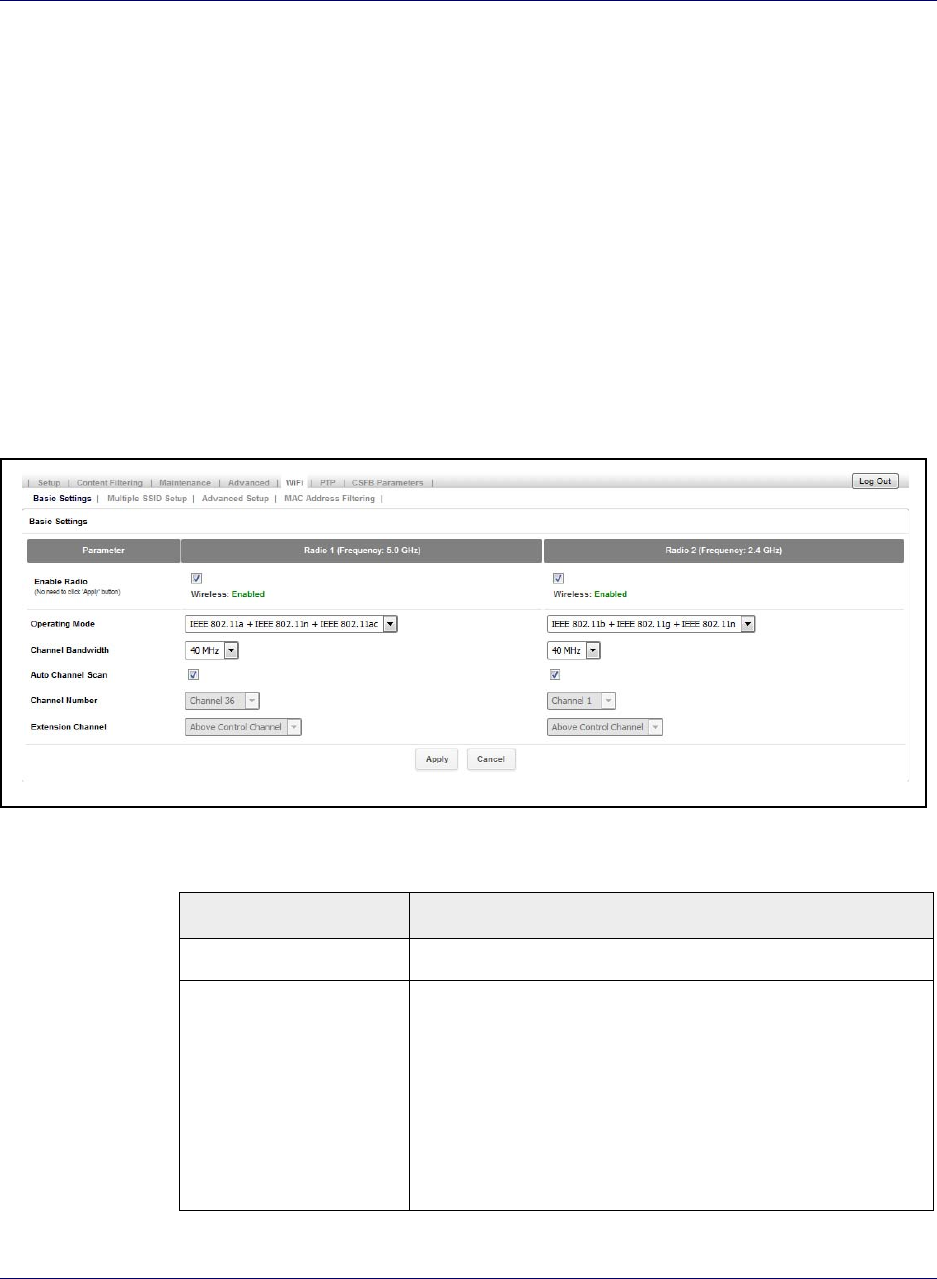
Basic Settings
On the Basic Settings tab, you to enable and configure the two radios available in the
S1000C. Radio 1 has a frequency of 5.0 GHz and Radio 2 has a frequency of 2.4 GHz
Figure 3-1. Basic Settings page
Table 3-1. Basic Settings parameters
Parameter Description
Enable Radio Enable or disable Radio 1 and Radio 2
Operating Mode The following options are supported on Radio 1:
• IEEE 802.11ac
• IEEE 802.11n
• IEEE 802.11a
The following options are supported on Radio 2:
• IEEE 802.11n
• IEEE 802.11g
• IEEE 802.11b
Chapter 3 Configuring the S1000C Router
3-6 913114 1.5.01 August 2016
DRAFT
3It is recommended to keep the ACS (Auto Channel Select) feature checked. This
feature ensures that the device will be able to select the most optimal available
channel, even in a congested RF environment.
Channel Bandwidth The following channel bandwidths are supported on Radio 1 and
Radio 2:
• 20 MHz
• 40 MHz
• 80 MHz
Auto Channel Scan To enable/disable auto channel scan, check/uncheck the box.
Channel Number This field shows the list of available channels under the respective
radio.
Note: To select a channel manually, the Auto Channel Scan option
must be disabled.
Extension Channel Automatically selected based on the selected channel
Table 3-2. Mode, bandwidth and data rate configurations
Mode Channel Bandwidth Data Rates
Radio 1 (5 GHz)
IEEE 802.11ac 20 MHz up to 87.6 Mbps
40 MHZ up to 200 Mbps
80 MHz up to 433 Mbps
IEEE 802.11n 20 MHz up to 72.2 Mbps
40 MHz up to 150 Mbps
IEEE 802.11a 20 MHz up to 54 Mbps
Radio 2 (2.4 GHz)
IEEE 802.11n 20 MHz up to 72.2 Mbps
40 MHz up to 150 Mbps
IEEE 802.11g 20 MHz up to 54 Mbps
IEEE 802.11b 20 MHz up to 11 Mbps
Table 3-1. Basic Settings parameters (continued)
Parameter Description
Chapter 3 Configuring the S1000C Router
S1000C User Guide, Release 1.5 3-7
DRAFT
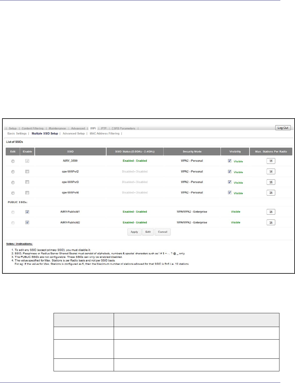
Multiple SSID Setup
The S1000C router supports twelve SSIDs. Eight SSIDs are Private and user
configurable; four are Public and configured only by the Operator.
1Click Multiple SSID Setup.
NOTE: Public SSIDs can only be enabled or disabled in the S1000 Router. Public
SSIDs are configured from the DMS Device Management Portal under Device
Configuration. Refer to DMS Device Management Portal User Guide for S1000
Devices (913157) for details.
Figure 3-2. Multiple SSID Setup page
Table 3-3. Multiple SSID List parameters
Parameter Description
SSID The name of the network to which a device associates
Enable To enable/disable a SSID, check/uncheck the box for the SSID. Click
Apply.
Status Shows the status of a SSID per Radio
Chapter 3 Configuring the S1000C Router
3-8 913114 1.5.01 August 2016
DRAFT
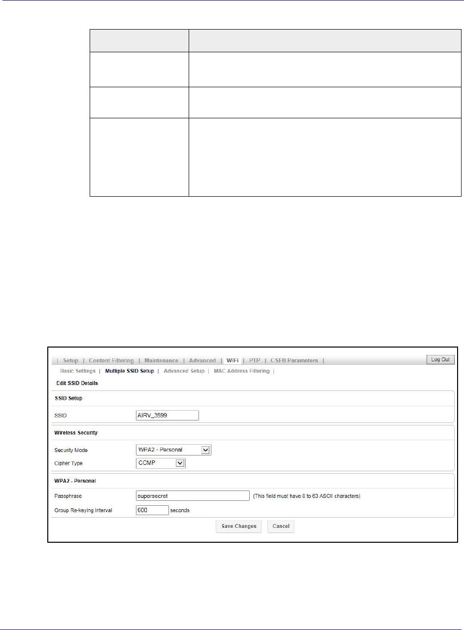
To edit an SSID
To edit SSID details:
1Find the SSID you want to modify, disable it (uncheck the Enable box), then click
Edit.
Figure 3-3. Edit SSID Details page
Security Mode Shows the security mode in which the SSID is currently operating
By default, the security mode is WPA2-Personal for Private SSIDs.
Visibility To enable/disable SSID broadcast, check/uncheck the box for each of the
Private SSIDs and click Apply.
Max. Stations Per Radio This feature can be used to restrict the number of connections per SSID. A
minimum of one station and a maximum of 128 stations can be specified
per SSID.
The maximum stations per radio is for the number of radios and not for
SSIDs. For example, if the value of Max. Stations Per Radio is configured
for 5, the maximum stations allowed for that SSID is 5 + 5, or 10 stations.
Table 3-3. Multiple SSID List parameters
Parameter Description
Table 3-4. Edit SSID Details parameters
Parameter Description
SSID Setup
SSID The name of the network to which a device can associate. SSID must
be in the range of 1 to 32 characters, and must be unique.
Note: If you want to change the name of the SSID, change the
text of the SSID text box, then click Save Changes. All SSID
values will remain the same; only the name will change.
Wireless Security
Security Mode The security mode in which the SSID is currently operating.
Valid values
• open
• WPA-Personal
• WPA-Enterprise
•WPA2-Personal
•WPA2-Enterprise
• WPA/WPA2-Personal
• WPA/WPA2-Enterprise
Note: For Enterprise versions, a RADIUS server based
security check is performed: You will enter values for Radius
Server:
– Server IP Address (A.B.C.D)
– Server Port (Range: 1 to 65535, Default: 1812)
– Server Shared Secret (WAP to Radius Server)
– Server re-keying interval; this is the time after which the
key must be re-generated. (Range: 600 to 7200 seconds,
0 - disable, Default: 600 seconds)
Cipher Type This field can be set to one of the following options:
• TKIP – Temporal Key Integrity Protocol
• CCMP – Counter Mode CBC MAC Protocol
• TKIP & CCMP
<Security Mode> - Personal
Passphrase Password required to associate with AP. This can be 8-63 ASCII
characters.
Group Re-keying interval The period of time between automatic changes of the group-key with
the devices on the network.
Chapter 3 Configuring the S1000C Router
S1000C User Guide, Release 1.5 3-9
DRAFT
Chapter 3 Configuring the S1000C Router
3-10 913114 1.5.01 August 2016
DRAFT
2Click Save Changes to save your configuration changes.
SSID IP configuration
To configure the IP address and subnet for an SSID, navigate to AdvancedLAN IP
Setup. On this page, you can view the various subnets, including the default IP
address range and subnet mask, for every WiFi SSID. You can edit these fields for
each SSID by clicking the Edit button for the SSID and entering new values.
Figure 3-4. LAN IP Setup page
Table 3-5. LAN IP Setup parameters
Parameter Description
SSID The name of the SSID.
IP Address The configured IP Address for the router for the SSID.
Format: <A.B.C.D>
Subnet Mask The configured subnet mask for the router in the SSID This is
calculated by the router based on the IP Address.
Format: <A.B.C.D> Default: 255.255.255.0
Chapter 3 Configuring the S1000C Router
S1000C User Guide, Release 1.5 3-11
DRAFT
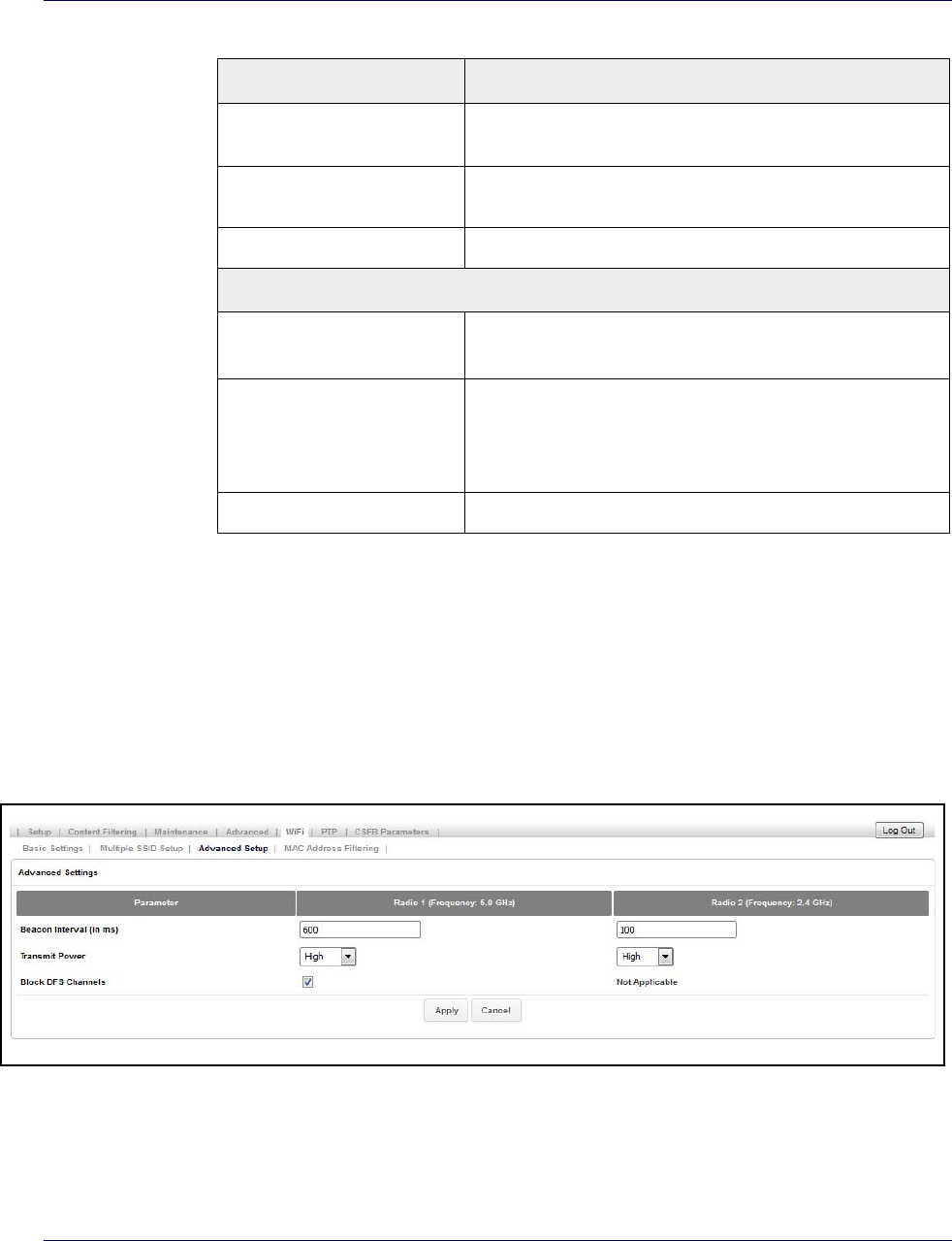
Advanced Settings
On the WiFi Advanced Setup page you can configure some WiFi advanced parameters
such as Beacon Interval, Transmit Power and Block DFS channel. Generally no
configuration change is required on this page.
Figure 3-5. Advanced Settings page
Starting IP The starting range of the reserved pool of IP Addresses for this
SSID.
Ending IP The ending range of the reserved pool of IP Addresses for this
SSID.
Edit Click this button to edit the configuration for the SSID.
Lan Interface Details
SSID Note: All parameters described above apply to the SSID
for the Local Area Network (LAN).
Default DMZ Server When checked, the IP Address for this “Demilitarized zone” is the
default server. The IP Address can be configured.
Note: Use this cautiously, as there are security issues
associated with a DMZ server.
Apply Click this button to commit the DMS server configuration.
Table 3-5. LAN IP Setup parameters (continued)
Parameter Description

Table 3-6. Advanced Settings parameters
Parameter Description
Beacon Interval Specifies the time in which a beacon packet must be broadcast.
By default, all the SSIDs will be beaconing at an interval of
100msec. (Range: 50 msec to 3500 msec)
Transmit Power This defines the strength of the signal being transmitted from a
radio.
By default, both the radios will be transmitting at the highest
Transmit Power.
Block Dynamic Frequency
Selection (DFS) Channels This option allows the Auto Channel Selection (ACS) mechanism
to either select/unselect DFS channels.
The following channels are classified as DFS channels:
52,56,60,64,100,104,108,112,116,120,124,128,132,136,140
By default, the 5GHz radio will block all the DFS channels. One
can enable the use of these channels by unchecking the checkbox
and applying the settings.
NOTE: It is NOT recommended to use these channels.
Chapter 3 Configuring the S1000C Router
3-12 913114 1.5.01 August 2016
DRAFT
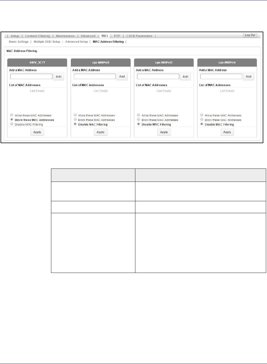
MAC Address Filtering
This feature is used to ALLOW or BLOCK MAC addresses from associating with a
Private SSID.
By default, this feature is DISABLED on every Private SSID.
Chapter 3 Configuring the S1000C Router
S1000C User Guide, Release 1.5 3-13
DRAFT
Figure 3-6. MAC Address Filtering page
Table 3-7. MAC Address Filtering parameters
Parameter Description
Add a MAC Address To add a MAC address in the list, enter a valid MAC address
in the text field provided under a SSID and click Add.
List of MAC Addresses Displays the list of MAC addresses added.
MAC Command This option is used to select the operation for the MAC
addresses added in the list.
• Allow these MAC Addresses – used to ALLOW only the
MAC addresses added to the list
• Block these MAC Addresses – used to BLOCK only the
MAC addresses added to the list
• Disable MAC Filtering – used to DISABLE MAC
Address Filtering
Chapter 3 Configuring the S1000C Router
3-14 913114 1.5.01 August 2016
DRAFT
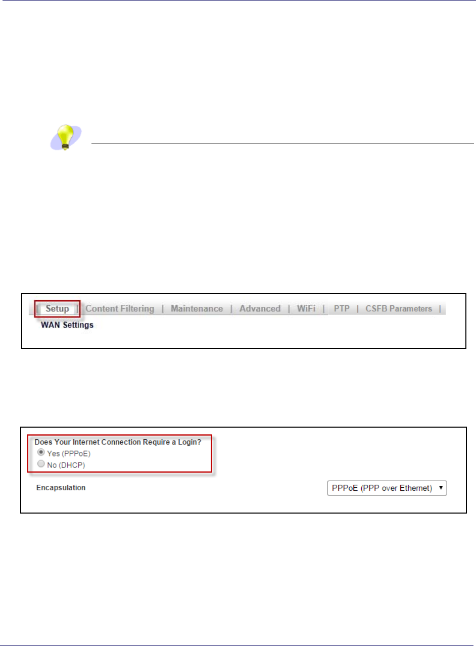
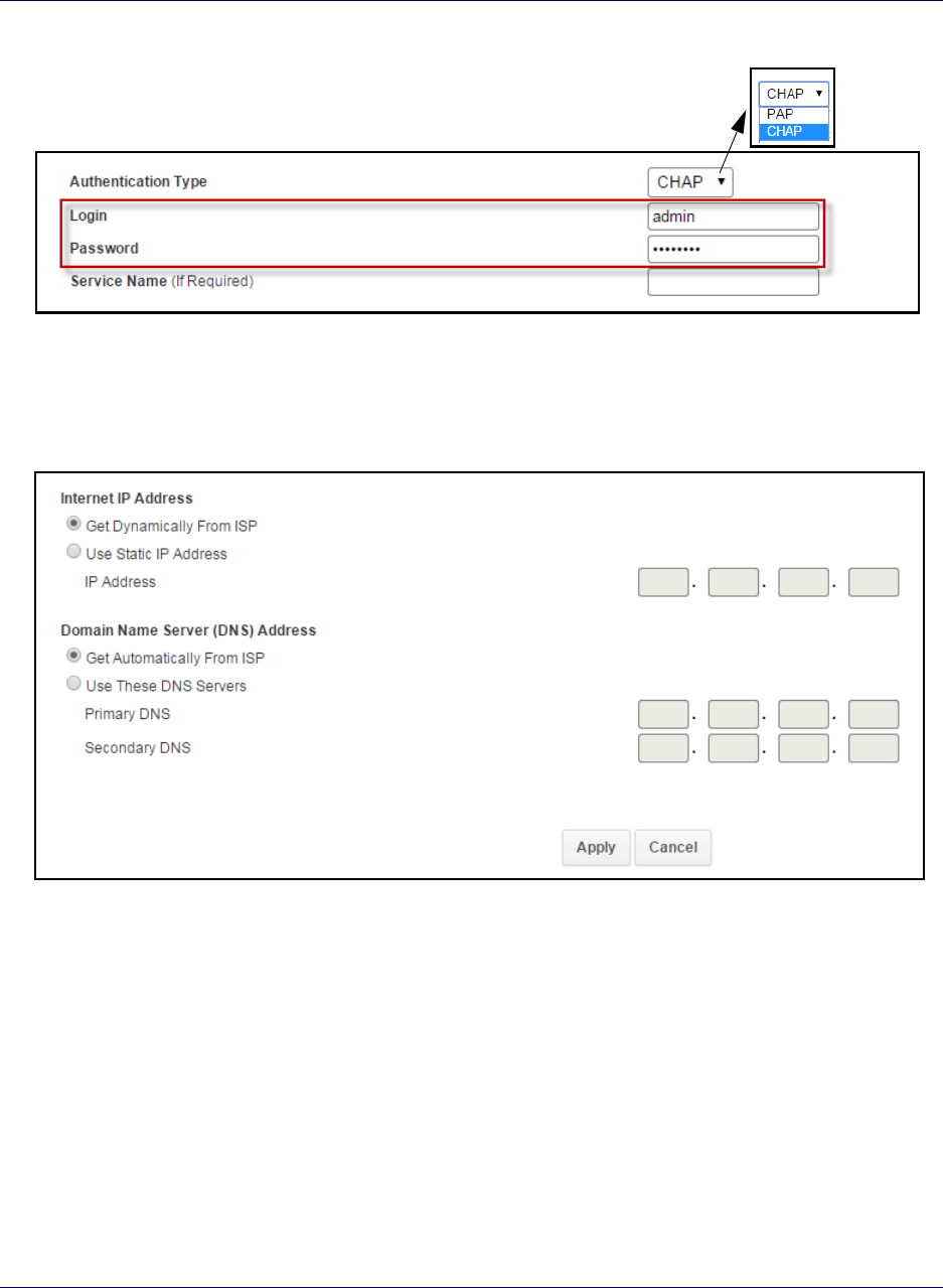
Adding your ISP User Name and Password
If you are using a DSL modem and your device cannot connect to the Internet, you
may need to enter your ISP account user name and password so that the S1000C can
connect to the Internet.
You will use the User Interface of the S1000C internal router to configure this
information.
TIP
Before you begin, obtain your ISP user name and password. Contact your ISP if
you do not have this information.
1Log into the S1000C router by following the procedure in Logging in to the
S1000C router.
2Click the Setup tab on the Router status page menu bar.
3Click WAN Settings.
4Ensure that Yes (PPPoE) is selected.
5Enter your ISP user name in the Login box and your password in the Password
box. Select authentication type (PAP, CHAP) from the drop down menu. Enter the
Service name information if you have it. Click OK.
Chapter 3 Configuring the S1000C Router
S1000C User Guide, Release 1.5 3-15
DRAFT
6Accept the defaults in other fields on the screen. Click Apply.
When the WAN LED is solid green your Internet connection is available. If
setting up PPPoE takes more than 15 minutes at startup, the WAN LED will turn
solid red. Once the PPPoE connection is set up, the LED turns solid green. If the
LED remains solid red, contact your ISP.

Chapter 3 Configuring the S1000C Router
3-16 913114 1.5.01 August 2016
DRAFT

S1000C User Guide, Release 1.5 4-1
DRAFT
Chapter 4
Using the S1000C
This chapter describes how the S1000C works at a high-level, and provides
maintenance guidelines.
•How the S1000C works on page 4-1
•How data goes over the Internet on page 4-4
•Using the External GPS Antenna on page 4-5
•Maintenance on page 4-6
How the S1000C works
The S1000C is a small cell base station with a radio unit that is similar to a cell tower
radio. The base station uses a low-power antenna to transmit data cellular signals in
your small and medium business locations.
Base stations give you better cellular coverage because they provide a stronger signal.
A strong signal can extend battery life. Also, data applications on Smartphones and
other mobile email devices, work faster.
WiFi
The S1000 has an internal router that supports dual band radios (2.4GHz and 5GHz).
Each radio supports 6 Virtual Access Points (VAP), 2 public and 4 private. Both radios
share SSIDs that are not editable across VAPs.
Users with dual band radio capable receivers will reap the benefits of shared SSID and
security credentials, and will enjoy a high quality user experience.
Users who travel out of range will migrate to the 2.4 GHz Radio band, and users near
the S1000 will migrate to the 5GHz Radio Band to utilize higher data rates.
You can manage the WiFi capabilities of the S1000 internal router. For more
information, see the Airvana S1000 Router Guide (913110).

Chapter 4 Using the S1000C
4-2 913114 1.5.01 August 2016
DRAFT
Broadband connection
The S1000C connects to an Operator’s network through a broadband Internet
connection.
Connection speed
The S1000C’s actual transmission speed is only as fast as the maximum broadband
connection speed. Internet congestion, the number of users on the provider’s network,
and other factors can decrease the actual broadband connection speed. Individual
bandwidth needs vary per customer. CommScope recommends a minimum of 3 Mbps
downstream and 1.8 Mbps upstream for data services.
The following table shows recommended bandwidth by usage type:
Usage Type Recommended Download
Speed Recommended Upload
Speed
Wireless Data Up to 3 Mbps per session Up to 1.0 Mbps per session
eCSFB
Circuit Switched Fallback (CSFB) enables circuit switched voice and SMS services to
be delivered to dual radio Long Term Evolution (LTE) devices such as the S1000.
Because the S1000 cannot process the 3G traffic internally, it switches the traffic
(“falls back”) to the 3G network running on the internal CMDA cFAP device.
In this release, the cFAP used is the C4500 (CDMA). The cFAP does not require
special configuration; the ability to discover and employ the services of the cFAP is
enabled by default.
Refer to the Airvana Small Cell Deployment Guide (913111) to learn more about the
eCSFB feature.
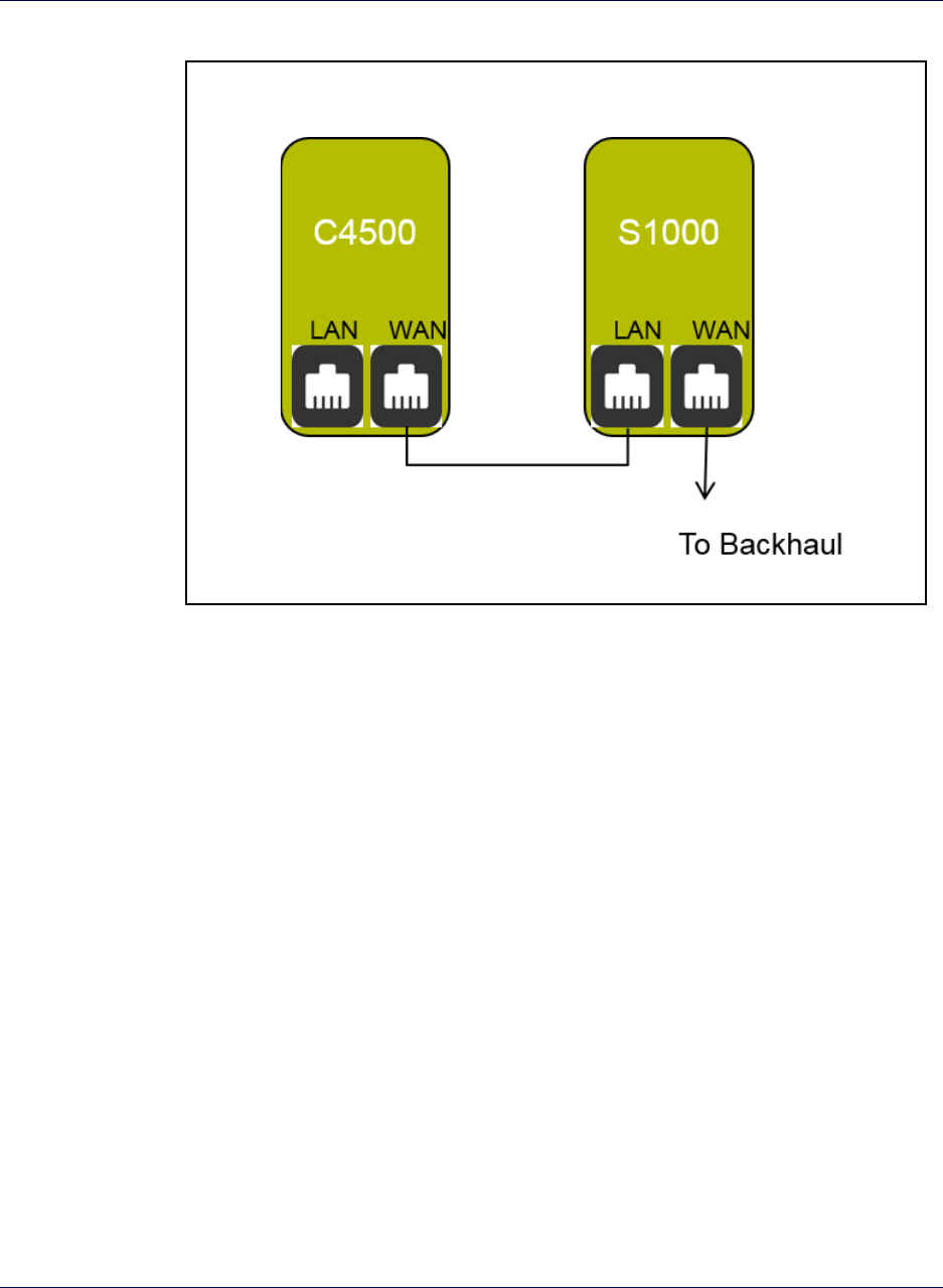
Discovery and data exchange
Figure 4-1 shows the internal layout of the S1000C. Data and voice traffic from the
backhaul passes through a switch and into the WAN port of the S1000 board. Data
traffic is handled by the 4G capabilities of the S1000 board. Voice traffic is routed to
the LAN port of the cFAP board to be processed on the 3G network.
Chapter 4 Using the S1000C
S1000C User Guide, Release 1.5 4-3
DRAFT
Figure 4-1. S1000C internal view
S1000C (internal view)
Discovery and information exchange
The S1000C WAN port is connected to a switch to the network backhaul. The cFAP
board’s WAN port is connected to the S1000 board’s LAN port.
1The S1000C FAP broadcasts its presence on its LAN port from boot up if CSFB to
cFAP is enabled and the PairedRefCellId parameter is configured.
2The cFAP device listens on the WAN port for broadcast messages.
3The cFAP device, upon receiving this message, acquires the S1000C
IP address/port number.
4The cFAP initiates a dedicated connection towards the S1000C, where the cFAP
and S1000 exchange CDMA2000 parameters.
5The interface is UDP based.
Refer to the Airvana S1000 Web GUI User Guide (913110) to learn more about
configuring the CSFB feature.
Chapter 4 Using the S1000C
4-4 913114 1.5.01 August 2016
DRAFT
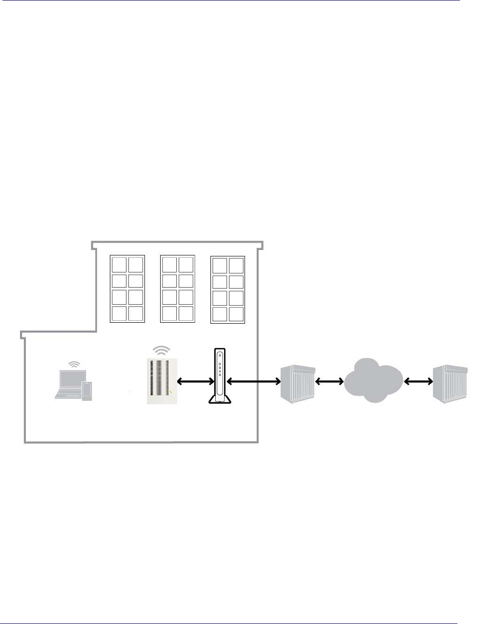
How data goes over the Internet
LTE data and voice traffic passes between the S1000C and the Internet over the
broadband connection device attached to the WAN port of the S1000C. Services and
applications provided by the ISP, such as Internet browsing, make use of this path.
Voice traffic is switched internally to the 3G network.
The S1000’s internal WiFi router generates signals on 2.4G and 5G modes. This WiFi
capability allows wireless devices, such as smartphones and tablets to connect to the
S1000C’s WiFi network and use local services such as data sharing and printing.
Access to the Internet for the users of the WiFi network is provided over the S1000C’s
WAN port. WiFi performance rates can be affected by the WAN connection speed
(refer to Broadband connection on page 4-2).
Figure 4-2. How data goes over the Internet
Wireless devices
using S1000C’s
WiFi and voice
capabilities
S1000C Broadband
Connection
Device
ISP
(Cable, DSL,
Fiber, optic)
Internet
Customer
Network

Chapter 4 Using the S1000C
S1000C User Guide, Release 1.5 4-5
DRAFT
Using the External GPS Antenna
Use the external GPS antenna if the internal antenna of your S1000C does not work
(indicated by a solid red GPS LED for more than 2 hours). Connect the external GPS
antenna to your device's GPS connection port.
If you use the optional GPS antenna:
• Place the external GPS antenna horizontally on a flat surface as close to a window
as possible. The antenna works best in an open area where it can easily pick up
signals.
• Do not place the GPS antenna:
• Outdoors; it is not weatherproof
• Behind large, heavy objects such as furniture; doing so could affect the signal.
Refer to External GPS antenna setup on page 2-9 for external GPS antenna setup.
TIP
Using the external GPS antenna in buildings with open floor plans allows the
S1000C to be positioned in a central location; improving coverage throughout the
building.

Chapter 4 Using the S1000C
4-6 913114 1.5.01 August 2016
DRAFT
Maintenance
With normal use, S1000C is maintenance-free. Follow the recommendations below to
ensure that it runs optimally.
Ventilation
The S1000C has ventilation slots that work best if you don’t block the flow of air to
them. For desk mounted devices, keep the device at least 2 inches (5 cm) from walls
and other surfaces to ensure proper air flow.
NOTE
For wall mounted devices, keep the a 6 inch (15 cm) clearance above and below
the device.
Cleaning
Dust the S1000C occasionally to keep air vents clear of debris. Do not use liquid
cleaners.

S1000C User Guide, Release 1.5 5-1
DRAFT
Chapter 5
Troubleshooting
This chapter contains tips and procedures to help you troubleshoot your S1000C.
•Troubleshooting installation problems on page 5-1
•Resetting the S1000C on page 5-3
•LED quick reference on page 5-4
•Router connection problems on page 5-7
•Using LEDs on page 5-9
•Using 4G DATA LEDs to diagnose Errors and Faults on page 5-11
•FAQs on page 5-16
•Getting help on page 5-19
For complete Troubleshooting information, refer to CommScope S1000
Troubleshooting Guide (913112).
Troubleshooting installation problems
If your Broadband turns solid red after 15 minutes, reversing the order of turning on
the S1000 and your broadband connection device can often resolve this problem. To
reverse the order, follow these procedures:
1Unplug all cables, including power cables from all devices. You can unplug
devices in any order.
2Connect all Ethernet and GPS cables as described in Setting up your S1000C on
page 2-4.
CAUTION
Do not connect any power cables at this point in the procedure.
3Plug the S1000C into an electrical outlet, preferably a surge protected outlet.

Chapter 5 Troubleshooting
5-2 913114 1.5.01 August 2016
DRAFT
4Wait 4 minutes.
5Plug your broadband connection device into an electrical outlet.
TIP
You may want to consult the documentation of your broadband connection device
for any special procedures for connecting a device directly to your broadband
connection device.
If the WAN LED turns solid red after 15 minutes, call Customer Support as described
in Getting help on page 5-19.
Chapter 5 Troubleshooting
S1000C User Guide, Release 1.5 5-3
DRAFT
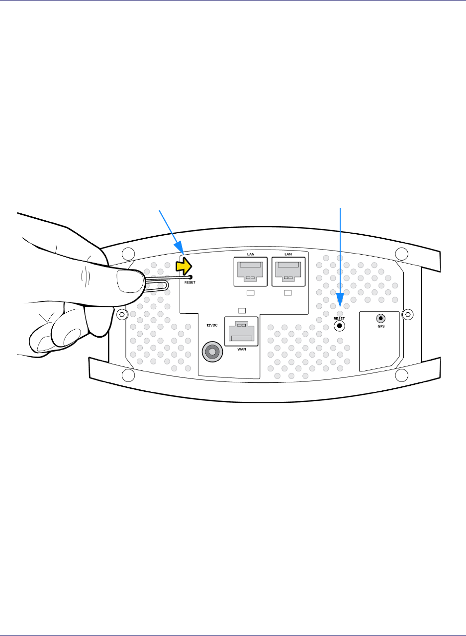
Resetting the S1000C
The S1000C has 2 reset buttons on the bottom of the unit.
If your S1000C operates properly for an extended period and the WAN LED on the
4G side of the device suddenly starts blinking red, the S1000 may have a problem
requiring a reset. To reset the S1000 board, push the Reset button for at least 10
seconds.
If the WAN LED on the 3G side starts blinking red, the CFAP may have a problem
requiring a reset. To reset the C4500 board, push the Reset button for at least 10
seconds.
Figure 5-1.
Reset the C4500 board Reset the S1000 board
Resetting the S1000C
After resetting, your S1000C goes through an automated setup sequence. During this
time, the device's green LEDs will be solid for a few seconds, and then all LEDs will
turn off until the software loads. The reset process may take 30-45 minutes.
After resetting the S1000C, if the failure persists, contact Customer Care. See Getting
help on page 5-19.
Chapter 5 Troubleshooting
5-4 913114 1.5.01 August 2016
DRAFT
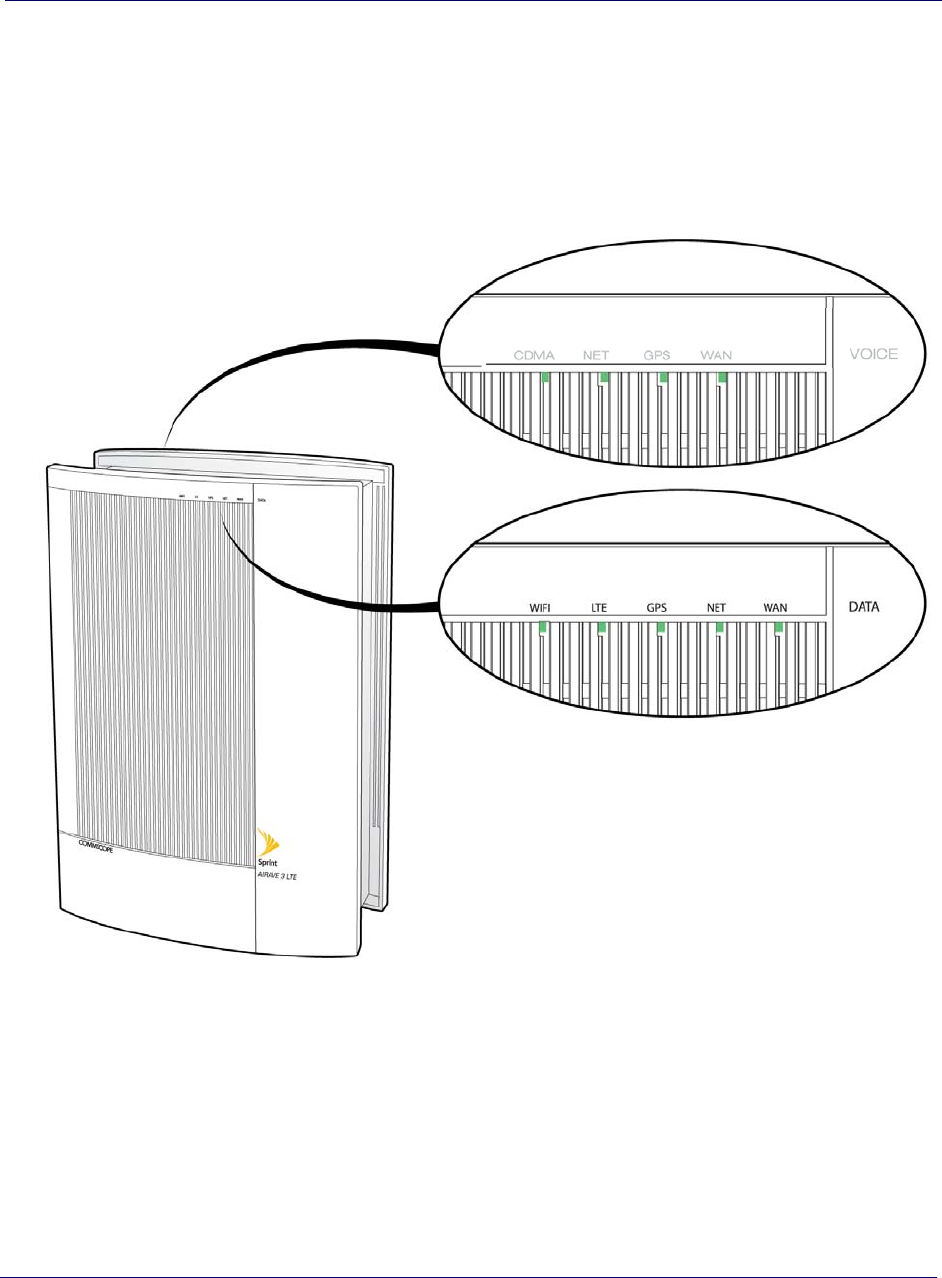
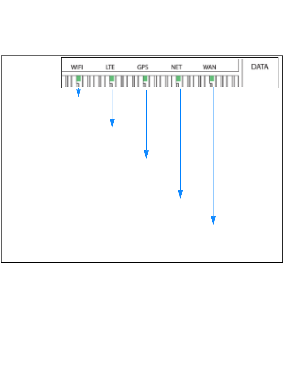
LED quick reference
Each side of the S1000C has a set of LEDs specific to 4G LTE or 3G VOICE.
Figure 5-2. S1000C LED layout
Chapter 5 Troubleshooting
S1000C User Guide, Release 1.5 5-5
DRAFT
4G DATA LEDs
Figure 5-3 shows the quick reference for data LED functions.
Figure 5-3. 4G
Solid Green: WiFi service UP
Solid Red: HW/WiFi service problem
Blinking Red: Wifi service error
Off: Wifi service or service disabled
Solid Green: LTE service UP
Solid Red: HW/LTE service problem
Blinking Red: LTE service error
Off: LTE service sector disabled
Solid Green: GPS Time Fix available
Solid Red: HW/GPS Time Fix
problem
Blinking Red: GPS Time Fix not
available
Solid Green: Ready
Solid Red: HW/connection problem
Blinking Red: IPSec tunnel error
Solid Green: Ready
Solid Red: HW/connection problem
Blinking Red: Service error
Data LEDs quick reference
Chapter 5 Troubleshooting
5-6 913114 1.5.01 August 2016
DRAFT
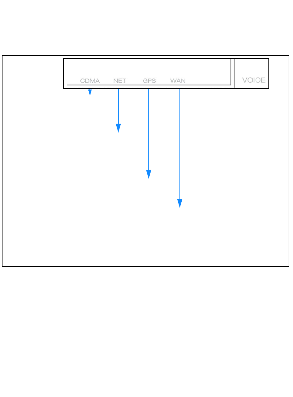
3G VOICE LEDs
Figure 5-3 shows the quick reference for voice LED functions.
Figure 5-4.
Solid Green: Ready
Blinking green: Accessing service
Solid amber: Hardware problem
Blinking Amber: Service error
Off: No service or service disabled
Solid Green: Ready
Blinking green: Initializing
Fast Blinking green: Active call
Solid Amber: Hardware problem
Blinking Amber: Service error
Off: Device not activated
Solid Green: Ready
Blinking Green: Acquiring a lock
Solid Amber: Hardware problem
Solid Green: Connected to the Internet
Blinking green: Initializing
Solid Amber: Hardware problem
Blinking Amber: Service error
Alternating Green/Amber: Software upgrade in progress
Off: No power
3G VOICE LEDs quick reference

Chapter 5 Troubleshooting
S1000C User Guide, Release 1.5 5-7
DRAFT
Router connection problems
If you cannot connect to the S1000C router, there may be a problem with the router,
use the following procedures to diagnose the problem.
Test for connectivity
If the router is properly installed, the LAN connection is OK, and it is powered ON,
test the connection by using the Ping command:
• Open the command prompt window and enter the command:
ping 192.168.16.1
• If no response is received, either the connection is not working, or your PC's IP
address is not compatible with the router's IP Address. Follow steps in Verify IP
addresses.
Verify IP addresses
If the PC is using a fixed IP address, its IP address must be within the range
192.168.16.2 to 192.168.16.254 to be compatible with the S1000 router’s default IP
address of 192.168.16.1. Also, the Network Mask must be set to 255.255.255.0.
•Refer to Airvana S1000 Web GUI User Guide (913110) for details on checking the
PC's TCP/IP settings.
• Ensure that your PC and the S1000C router are on the same network segment.
• Ensure you are using the wired LAN interface.
Common connection types
Table 5-1. Common connection types
Type Details ISP Data required
Dynamic IP Address Your IP Address is allocated
automatically, when you connect
to your ISP.
Some ISPs may require a particular
Hostname or Domain name, or MAC
(physical) address.
Static (Fixed) IP
Address Your ISP allocates a permanent IP
Address to you. Usually, the
connection is “Always on.”
The IP Address allocated to your PC,
and related information, such as
Network Mask, Gateway IP address,
and DNS address.
PPPoE, PPPoA Your PC connects to the ISP only
when required. The IP address is
usually allocated automatically.
User name and password are always
required. If using a Static (Fixed) IP
address, you need the IP address and
related information (Network Mask,
Gateway IP address, and DNS address).

Chapter 5 Troubleshooting
5-8 913114 1.5.01 August 2016
DRAFT
IPoA (IP over ATM) Normally, the connection is
Always on. The IP Address allocated to your PC
and related information, such as
Network Mask, Gateway IP address,
and DNS address.
Table 5-1. Common connection types (continued)
Type Details ISP Data required
Chapter 5 Troubleshooting
S1000C User Guide, Release 1.5 5-9
DRAFT
Using LEDs
Use the LEDs to troubleshoot your device.
4G DATA LEDs
Table 5-2 lists 4G DATA LEDs. Use these LEDs to troubleshoot LTE data issues with
your device.
Table 5-2. 4G DATA LED usage and description
LED Display Pattern S1000 State Description
WAN
WAN port connected The WAN port is connected to a peer and has
obtained an IP address over the local network
WAN port not
connected
-or-
hardware error
The WAN port not connected to a peer, or has not
obtained an IP address (more than 15 minutes)
-or-
a hardware error occurred during startup
WAN port not
connected The WAN port is not connected to a peer, or has not
obtained an IP address (15 minutes or less)
NET
IPSec tunnel is
established The IPSec tunnel is established to the Operator’s
core network and is functioning properly
IPSec tunnel is either
down or re-establishing
-or-
hardware error
The IPSec tunnel to the Operator’s core network is
down, or has not established a connection (more
than 15 minutes)
-or-
a hardware error occurred during startup
IPSec tunnel is DOWN
or setting up The IPSec tunnel to the Operator’s core network has
gone down or has not come up since boot-up. (15
minutes or less)
Chapter 5 Troubleshooting
5-10 913114 1.5.01 August 2016
DRAFT
GPS
GPS Time Fix is
available The current GPS Time Fix is available
GPS Time Fix has not
been achieved
-or-
hardware error
GPS Time Fix has not been achieved since boot-up
or DSP reload (30 minutes or more)
-or-
a hardware error occurred during startup
GPS Time Fix is not
available The current GPS Time Fix is not available, including
the GPS Holdover case.
In poor GPS reception conditions, the device
can go into GPS Holdover. The Holdover is 24
hours. During this time LTE services are
available. The GPS led will blink red even
though LTE service is still available. If you see
this condition call Customer Care.
LTE
LTE service is UP LTE service is UP
LTE service is DOWN
-or-
hardware error
LTE service has not come up (30 minutes or more)
-or-
a hardware error occurred during startup
LTE service is coming
up or coming down LTE service has not come up since boot-up, or
has gone down
LTE service is turned
Off. The LTE service sector has been turned off from the
DMS
Table 5-2. 4G DATA LED usage and description (continued)
LED Display Pattern S1000 State Description
Chapter 5 Troubleshooting
S1000C User Guide, Release 1.5 5-11
DRAFT
NOTE
In the table above, a hardware error is indicated only if all LEDs are in the Red
Solid display pattern.
Using 4G DATA LEDs to diagnose Errors and Faults
The following table shows some of the general errors and fault conditions that you
may encounter with data traffic on the S1000C. Use the table to help diagnose and
resolve potential problems with your device setup.
Refer to Table 5-2 for LED color codes.
WIFI
WiFi service is UP 2.4 GHz, 5.0 GHz or both WiFi services are UP
WiFi service is DOWN
-or-
hardware error
WiFi service has not come up (30 minutes or more)
-or-
a hardware error occurred during startup
WiFi service is coming
up or coming down Wifi service has not come up since boot-up, or
has gone DOWN.
WiFi service is OFF WiFi service has been turned OFF either from the
DMS or via local device GUI
Table 5-2. 4G DATA LED usage and description (continued)
LED Display Pattern S1000 State Description
Table 5-3. LED error and fault conditions
WAN NET GPS LTE WIFI S1000C Error/Fault
HW error detected
Chapter 5 Troubleshooting
5-12 913114 1.5.01 August 2016
DRAFT
WAN port is connected; IPSec tunnel
is UP; GPS Holdover; LTE and WiFi
Service is UP.
WAN port is connected; IPSec tunnel
is UP; GPS Time Fix is not
available; LTE Service is DOWN;
WiFi Service is UP.
WAN port is connected; IPSec tunnel
is DOWN; GPS Time Fix is
available; LTE service is DOWN;
WiFi service is UP.
WAN port is connected; IPSec tunnel
established and UP; GPS Time Fix is
available; LTE service could not
come up; WiFi service is UP.
WAN port is connected; IPSec tunnel
established and UP; GPS Time Fix is
available; LTE service is UP; 2.4
GHz and 5.0 GHz WiFi Service
could not come up.
Table 5-3. LED error and fault conditions (continued)
WAN NET GPS LTE WIFI S1000C Error/Fault
Chapter 5 Troubleshooting
S1000C User Guide, Release 1.5 5-13
DRAFT
3G VOICE LEDs
Table 5-4 lists 3G VOICE LEDs. Use these LEDs to troubleshoot voice traffic issues
with your device.
NOTE
If all LEDs are Solid Amber, the C4500 cannot pass a hardware self-test. Call
Customer Support as described in Getting help on page 5-19.
Table 5-4. 3G VOICE LED display patterns and actions
LED Display Pattern Action to take
CDMA
Solid green None. Ready state.
Blinking green Wait. Accessing service.
Solid amber Hardware problem. Call Customer Support as
described in Getting help on page 5-19.
Blinking amber Service error. Plug the telephone line into a phone and
restart your device by turning the power off and on. If
this problem persists, call Customer Support as
described in Getting help on page 5-19.
Off No service or CDMA service has not been activated.
To activate CDMA service, contact Customer Support
as described in Getting help on page 5-19.
NET
Solid green None. Ready.
Fast blinking green None. Active call
Blinking green Wait. Your device is initializing.
Solid amber hardware problem. Call Customer Support as
described in Getting help on page 5-19.
Blinking amber No service. Restart the device by turning the power
off and on. If this problem persists, call Customer
Support as described in Getting help on page 5-19.
Off The CDMA board is not activated. Call Customer
Support as described in Getting help on page 5-19.

Chapter 5 Troubleshooting
5-14 913114 1.5.01 August 2016
DRAFT
GPS
Solid green None. GPS is ready.
Blinking green GPS is trying to aacquire a lock. Perform the
following steps if the GPS LED does not turn solid
green within 30 minutes:
• If you have not already done so, connect the
external GPS antenna to your device.
• If the external GPS antenna is already
connected, move it to a different location, as
close to a window as possible.
• If this problem persists, call Customer
Support as described in Getting help on
page 5-19.
Solid amber Restart the device by turning the power off and
on. If this problem persists, call Customer
Support as described in Getting help on
page 5-19.
Table 5-4. 3G VOICE LED display patterns and actions (continued)
LED Display Pattern Action to take

Chapter 5 Troubleshooting
S1000C User Guide, Release 1.5 5-15
DRAFT
WAN
Solid green None. Connected to the Internet.
Blinking green Wait. Accessing the Internet connection.
Alternating blinking
green and amber Wait. Software upgradein progress.
Solid amber Hardware problem. Call Customer Support as
described in Getting help on page 5-19.
Blinking amber Service error. Failed to acquire the Internet
connection.
• Check if your broadband modem or
broadband router has a problem. Reset your
broadband connection device. If the problem
with the broadband device persists, contact
your Internet service provider (ISP).
• Ensure that the S1000C’s router is correctly
configured to access the Internet service. See
Configuring WiFi service on page 3-5.
• Restart the device by turning the power off
and on.
• If this problem persists, call Customer
Support as described in Getting help on
page 5-19.
Off • The LED is not working or the unit has no
power. If this problem persists, call Customer
Support as described in Getting help on
page 5-19.
Table 5-4. 3G VOICE LED display patterns and actions (continued)
LED Display Pattern Action to take

Chapter 5 Troubleshooting
5-16 913114 1.5.01 August 2016
DRAFT
FAQs
Why does the S1000C need a GPS antenna?
The S1000C has a GPS antenna so that it can:
• Synchronize properly with the rest of the Operator’s network.
• Determine and select the correct radio frequencies available in your area so that
the S1000C uses the correct ones.
Why does the S1000C need an external GPS antenna?
Your device needs the external antenna only when the internal GPS antenna cannot
lock on to sufficient satellite signals. The external antenna lets the S1000C lock on to
the greatest number of satellites.
What should I do if the GPS fails to acquire a lock?
NOTE
For first-time S1000C startup, it could take up to 2 hours for the S1000C to achieve
GPS lock.
If you have not already connected the external GPS antenna, connect the antenna
following the steps in When is your S1000C ready to use? on page 2-7.
If you have connected the external GPS antenna and the GPS LED blinks red after 30
minutes, the GPS has failed to acquire a Time Fix. The S1000C will go into GPS
Holdover for a 24 hour period. Call Customer Care during this time period.
What happens to the S1000C if there is a power outage or if you lose
Internet access?
The S1000C needs both a broadband Internet connection and a constant power supply
to work. During a power outage your device will immediately switch to the Sprint
network.
Can you move the S1000C to another location?
Yes, you can move your device to another location within the Sprint network.
However, to move your device to a different address, you must first update your
service address by logging into your account on www.sprint.com.

Chapter 5 Troubleshooting
S1000C User Guide, Release 1.5 5-17
DRAFT
I have a DSL modem and cannot connect to the Internet
If you are using a DSL modem and your S1000C cannot connect to the Internet, you
may need to enter your Internet service provider (ISP) account user name and
password so that the device can connect to the Internet. See Adding your ISP User
Name and Password on page 3-14.
You may also need to adjust the WiFi settings. See Configuring WiFi service on
page 3-5.
My calls work fine outside but drop indoors
If you are notice poor coverage indoors, check the LTE and WIFI LEDs. If you see a
solid or blinking red WIFI LED you may also need to adjust the WiFi settings. See
Configuring WiFi service on page 3-5.
If the problem persists contact Customer Care.
My Internet connection is slow when my laptop is connected to the
S1000C
If you are experiencing slow Internet speeds when your laptop is connected to the
LAN port of your S1000C, you may need to change the bandwidth speed on your
S1000.
1Connect your laptop to the LAN port of your S1000C and disable WiFi.
2In a Web browser on your laptop, go to a Web site to test the uplink speed.
NOTE: Contact Customer Care for the URL to a recommended Web site. See
Getting help for Customer Care contact information.
3Run a speed test on your uplink speed. Note the maximum speed value.
4In a Web browser, enter the following IP address:
192.168.16.1
Chapter 5 Troubleshooting
5-18 913114 1.5.01 August 2016
DRAFT
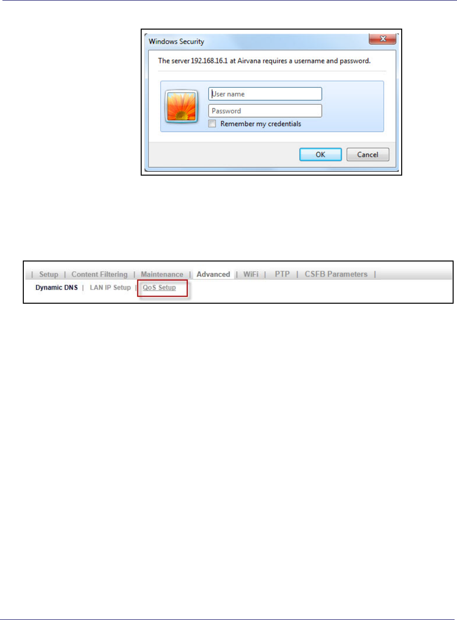
5Enter User name ‘admin’ and Password ‘admin’. Click Log In.
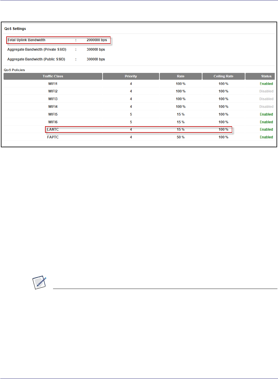
6In the Advanced tab, click Qos Setup.
7Verify that the Total Uplink Bandwidth value is large enough to support the value
recorded from the uplink test. You will need to consider the rate and priority
assigned to the LANTC traffic class.
Chapter 5 Troubleshooting
S1000C User Guide, Release 1.5 5-19
DRAFT
8If the problem persists, check the QoS setting in your home router. Ensure that the
S1000 has the highest priority. See the home router’s user manual for instructions.
9If the problem persists, contact your Internet Service Provider.
Getting help
If you need help with your S1000C, contact Customer Care.
• Online at www.commscope.com/support
•By Phone: Sprint Customer Care (888-206-3585)
NOTE
Call your Internet Service Provider for Internet access troubleshooting.
e interference by one of the following measures:
• Re-orient or relocate the receiving antennas of other devices.
• Increase the separation between the S1000C and other device receivers.
• Connect the S1000C into an outlet on a circuit different from that to which the
other device receiver is connected.

Chapter 5 Troubleshooting
5-20 913114 1.5.01 August 2016
DRAFT
• Consult the dealer or an experienced radio/TV technician for help.

S1000C User Guide, Release 1.5 6-1
DRAFT
Chapter 6
Safety information
This chapter contains safety information for your S1000C.
•General precautions on page 6-1
•FCC information on page 6-2
General precautions
• Dust the S1000C occasionally to keep air vents clear of debris. Do not wash it.
• The S1000C has ventilation slots that work best if you don’t block them. Keep the
S1000C at least 2 inches (5 cm) from walls and other surfaces to ensure proper air
flow.
• Do not operate the S1000C in an extremely dusty or humid environment.
• Avoid placing the S1000C near radiators or other heating sources.
• Avoid locating the S1000C where it could be exposed to direct sunlight for
prolonged periods.
• Do not connect the S1000C to a power strip containing an excessive number of
other devices.
• Although your S1000C is quite sturdy, it is a complex piece of equipment and can
be broken. Avoid dropping, hitting, bending, or sitting on it.
• Do not immerse the S1000C in water or get it wet. If your device does get wet,
unplug it immediately until it dries.
• Do not allow children to play with the S1000C. They could hurt themselves and
others or damage the device.
NOTE
For the best care of your S1000C, only CommScope-authorized personnel should
service your device and accessories. Failure to do so may be dangerous and void
your warranty.

Chapter 6 Safety information
6-2 913114 1.5.01 August 2016
DRAFT
FCC information
FCC ID: QHY-S1000C
! FCC radiation exposure statement
WARNING
Changes or modifications not expressly approved by CommScope could void your
authority to operate the equipment.
This device complies with FCC’s RF radiation exposure limits set forth for an
uncontrolled environment under the following conditions:
This device complies with FCC’s RF radiation exposure limits set forth for an
uncontrolled environment under the following conditions:
• This device should be installed and operated such that a minimum separation
distance of 8 inches (20 cm) is maintained between the radiator (antenna) and the
user’s or nearby person’s body at all times.
• This transmitter must not be co-located or operating in conjunction with any other
antenna or transmitter.
For more information, see the publication Femtocells and Health at
http://www.femtoforum.org or visit the FCC website at www.fcc.gov.
FCC Part 15
This device has been tested and found to comply with the limits for a Class B digital
device, pursuant to Part 15 of the FCC Rules. These limits are designed to provide
reasonable protection against harmful interference in a residential installation. This
device generates, uses, and can radiate radio frequency energy and, if not installed and
used in accordance with the instructions, may cause harmful interference to radio
communications. However, there is no guarantee that interference will not occur in a
particular installation. If this device does cause harmful interference to radio or
television reception, which can be determined by turning the device off and on, the
user is encouraged to try to correct the interference by one of the following measures:
• Re-orient or relocate the receiving antennas of other devices.
• Increase the separation between the S1000C and other device receivers.
• Connect the S1000C into an outlet on a circuit different from that to which the
other device receiver is connected.
• Consult the dealer or an experienced radio/TV technician for help.

S1000C User Guide, Release 1.5
B

S1000C User Guide, Release 1.5
913114 1.5.01 August 2016
CommScope
250 Apollo Drive
Chelmsford, MA 01824, USA
Phone:
North America +1 (877) 855-4092 (toll free)
International: +1 (978) 250-3100
Fax: +1 (978) 250-3910
DRAFT