Communication Components BDA-1819-60 BI-DIRECTIONAL AMPLIFIER User Manual New manual
Communication Components Inc BI-DIRECTIONAL AMPLIFIER New manual
UserManual.wiki
>
Communication Components
>
BDA-1819-60 User Manual
>
New manual
Contents
1.
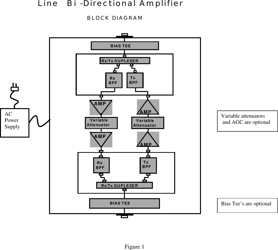
MANUAL TECH DESC LABEL FORMAT BLK DIAGRAM
2.
New manual
New manual
Navigation menu
Upload a User Manual
Namespaces
Wiki Guide
HTML
PDF
Info
Views
User Manual
Discussion / Help
Navigation