Communication Components BDA-1819-60 BI-DIRECTIONAL AMPLIFIER User Manual New manual
Communication Components Inc BI-DIRECTIONAL AMPLIFIER New manual
Contents
- 1. MANUAL TECH DESC LABEL FORMAT BLK DIAGRAM
- 2. New manual
New manual

INSTALLATION MANUAL
for
BI-DIRECTIONAL AMPLIFIERS
Communication Components Inc.
299 Forest Ave, Paramus, N.J. 07652 Tel: 201-265-8882, Fax: 201-265-8922
TABLE OF CONTENTS
1. Theory of Operation
2. Intended Application
3. Technical Description
4. Installation Procedure
5. Antenna installation safety precautions

1. THEORY OF OPERATION
The BDA-1819-60 is a bi-directional amplifier. It. is designed to exchange radio
communications in buildings, basements, tunnels and other RF shielded environments.
The BDA improves the sensitivity of base stations in indoor locations where there is a
significant amount of cable loss in RF distribution systems.
It contains two amplifiers providing amplification of RF signals in Up-link and Down-link
frequency bands. They are connected to the external cables via frequency selective
duplexers in order to attenuate all signals that are not in the designated bands.
2. INTENDED APPLICATION
BDA is intended for commercial non-consumer applications and has to be installed by
PCS service providers or their qualified subcontractors at the locations where the signal
strength from the base station is insufficient to provide quality communication service.
Unit is not intended for in-home use to boost output of typical consumer type transmitters
(phones, wireless local loops, etc).

3. TECHNICAL DESCRIPTION
The BDA-1819-60 bi-directional amplifier provides signal amplification in two separate
frequency bands in both directions between two coaxial connector terminals. It is achieved
by utilization of two frequency selective duplexers, which direct signals at two frequency
bands present at the common port in two outputs. These duplexers provide sufficiently
high isolation between two paths to prevent self-oscillation of the system. Detailed block-
diagram is shown in Figure 1.
The amplifier consists from several gain stages with the low noise stage at the input and
medium power stage at the output. All amplifier stages operate at class A linear regime in
order to provide the lowest possible intermodulation products.
The duplexer serves two purposes: it splits the signal from the common port to two
different ports, and it provides frequency selectivity and isolation between two paths. The
common port of the first duplexer is called “BASE STATION”. The common port of the
other duplexer is called “SERVICE AREA”.
Only signals within the frequency range of 851-866 MHz band will be amplified coming
from the BASE STATION port and only signals within the frequency range of 806-821
MHz band will be amplified from the SERVICE AREA port.
In this configuration the BDA amplifies signals in the Up-link band in one direction and
signals in the Down-link band in the other direction.
Physically the BDA block consists of a single compact unit with two RF connectors. It is
rugged and can be easily connected during cable installation. It has a moisture proof
NEMA 4X enclosure suitable for indoor and outdoor installation with two low noise
medium power amplifiers, optional independently controlled Up-link and Down-link
attenuators, two duplexers, and optional bias tee’s.
The BDA can be powered by a conventional 110/220 VAC source using a built-in power
supply or alternatively DC voltage can be supplied to the BDA via an external DC input
or via center conductor of the RF coax cable.
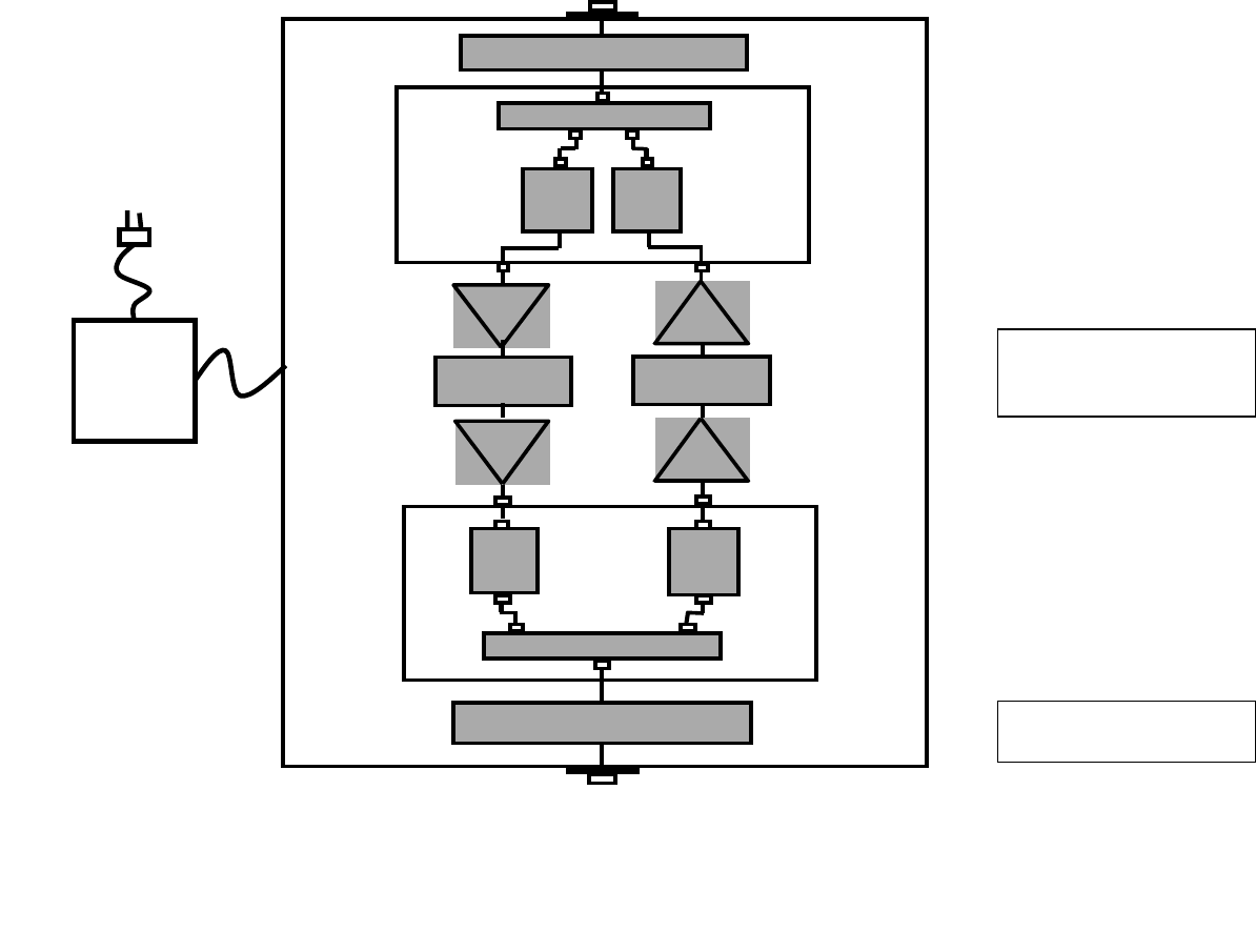
Figure 1
Line Bi -Directional Amplifier
BLOCK DIAGRAM
Rx/Tx DUPLEXER
Rx
BPF Tx
BPF
Rx/Tx DUPLEXER
BIAS TEE
Rx
BPF
Tx
BPF
BIAS TEE
AMP
AMP
V
ariable
Attenuator
AMP
AMP
V
ariable
A
ttenuator
Variable attenuators
and AGC are optional
AC
Power
Supply
Bias Tee’s are optional

4. INSTALLATION PROCEDURE
4.1 NSPECTION
Open the enclosure of the bi-directional amplifier (BDA) and carefully inspect the inside
assembly of the unit.
Verify that all components are properly secured to the base of enclosure, there are no lose
parts, and all interconnections are reliable.
4.2 SITE INSTALLATION
4.2.1 The bi-directional amplifier can be installed as a freestanding unit lying on the shelf
of the cabinet or any other adequately strong support. It can also be secured by screws to
the wall or rack using four holes in the tabs located at the back plate of the enclosure. It is
recommended that the environmental temperature will not exceed 65 C and the area will
be adequately ventilated.
4.2.2 Once amplifier is installed in place, open the front door and verify that all internal
parts are securely mounted.
4.2.3 Connect the ground wire to ground stud on the enclosure.
4.2.4 Plug in the AC cable into the AC socket to turn on the amplifier. The green light on
the enclosure must be lit on.
4.2.5 Connect spectrum analyzer to the input (donor antenna) cable. Measure the signal
level in the cable coming into the Down-link port of the amplifier. If the signal level is
above –40 dBm, add attenuator with the corresponding value or use internal attenuator, if
the BDA option is so equipped.
4.2.6 Repeat the same for the cable that will be connected to the Up-link port of the
amplifier.
4.2.7 Connect the spectrum analyzer via 20 dB pad to the Down-link port of the BDA.
CAUTION
Use caution working with the bi-directional amplifier.
Disconnect the 115 VAC from the amplifier prior to
inspection.

Connect the “donor” side cable to the Up-link port of the BDA. Observe the level of the
amplified signals on the spectrum analyzer. Adjust the gain (if the BDA option is so
equipped) or external (internal, if so equipped) attenuator value to limit the power of the
signals to +23 dBm for CDMA, +26 dBm for GSM, or +25 dBm for TDMA
applications.
4.2.8 Repeat the same measurements connecting the spectrum analyzer to the Up-link
port and cable to the Down-link port. Adjust the level of amplified signals at the Up-link
port to +23 dBm for CDMA, +26 dBm for GSM, or +25 dBm for TDMA applications.
4.2.9 Record the settings of attenuators.
4.2.10 Connect the Up-link cable to the amplifier. Check the security of the installation
and presence of the AC power. Amplifier is ready for operation.
4.3 REMOVE BI-DIRECTIONAL AMPLIFIER
4.3.1 Unplug the AC cord from the socket. AC light on the amplifier must be off.
Disconnect all coaxial cables.
4.3.2 Dismount amplifier from the wall or remove it from the shelf.
4.4 SHIPMENT AND STORAGE OF THE BDA
4.4.1 Use common technical shop practices to ensure equipment protection during
shipment or storage.
4.5 TROUBLESHOOTING AND FAULT DETECTION
4.5.1 Check the presence of the AC power. The AC light must be on.
4.5.2 Check the continuity of all connecting cables.
4.5.3 If the fault was not located, remove the amplifier and send it to the manufacturer for
repair.
4.5.4 RF testing of the amplifier is possible in the specially equipped laboratory.
WARNING!
110 VAC CAN BE LETHAL!
ALWAYS UNPLUG THE AMPLIFIER
BEFORE SERVICING THE INTERIOR.
.

4.6.0 INFORMATION TO USER
Any changes or modifications to this product as well as usage outside of specified
electrical parameters, which are not expressly approved by manufacturer, could void
the user’s authority to operate the equipment.
5. Antenna Installation Safety Recommendations
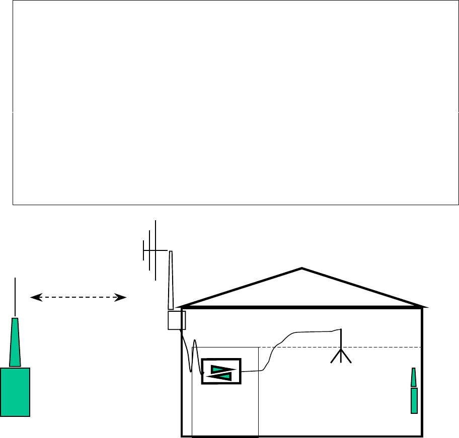
Typical installation is shown in Fig.2 Two antennas are used in this set-up. One antenna
with higher gain (10 dbi typically) and narrow beam, which is called Donor Antenna, is
pointed to the Base Station. It provides down-link signals for the BDA input and directs
up-link signals from the output of BDA to the Base Station.
The second antenna, which is called Service Antenna, usually located on the ceiling of the
service area. Low gain omni-directional antenna is normally used with typical gain 5 dBi
to 2 dBi.
Because antennas are open space radiating structures, the following precautions are
recommended:
Do not make any RF interconnections while BDA is operating
Do not approach Donor Antenna closer than 1 ft when the BDA
is operating. Mark the installation site accordingly.
Service Antenna must be installed sufficiently high in such a
way that the distance between the antenna and the mobile
phone user will always be more than 1 foot.
Do not use antennas with gain above 10 dBi in the service area.
Fig. 2
BS HH Radio
Donor
Antenna
Closet
BDA
Service
Antenna