Communication Components CE-1819-10 PCS Band Repeater User Manual PCS GSM Multi channel Cell Extender pub
Communication Components Inc PCS Band Repeater PCS GSM Multi channel Cell Extender pub
Manual
General Information
Communication Component Inc.’s Cell Ex-
tender products are designed to extend the
range and coverage area of Micro Base Sta-
tions in all GSM PCS applications. The Cell Ex-
tender boosts the output power of the Micro
Base Stations to match the levels of conven-
tional Base Stations allowing for cost efficient
implementation of high capacity radio networks.
It also or may -noise amplification of the receive signal to improve system
sensitivity and to maintain a balanced link of the transmit and receive sig-
nals.
The Cell Extender is easy to install, requires no maintenance, and is fully
compatible with a variety of Base Station equipment including the Ericsson
2308 series and Nortel E-cell series Micro-BTS. The Cell Extender offers
the maximum installation flexibility by allowing the Micro Base Stations to
be physically distanced from the antenna and mounting structure. This
overcomes the key installation drawback of the Micro Base Stations which
requires both a T1 connection and an AC connection on the mounting
structure. Three installation options are available.
General Info and
Configurations
1
Electrical Specifications &
Mechanical Specifications
2
Additional Information,
Options, and Ordering
3
Block Diagram &
Mechanical Drawing
4
Contents
Configuration 1 - The CE-1819-10 can be mounted on the same mounting structure directly above
or below the Micro Base Station. This option is ideal when an existing Micro Base Station site is be-
ing upgraded with a Cell Extender or when both AC and T1 connections are available on the mount-
ing structure.
Configuration 2 - The Micro Base Station is installed at ground level or indoors and the Cell Ex-
tender is mounted on the mounting structure, in close proximity to the antenna. This configuration is
ideal for environments where AC lines and T1-connections are not easily available on the mounting
structure or when it is desired to keep the Micro Base Station indoors. For this configuration, the
Cell Extender should be ordered with the Remote Power Option which includes a Bias-t and Remote
Power Supply module to provide DC power to the Cell Extender over the coax cable.
Configuration 3 - Both the Micro Base Station and the Cell Extender are installed at the ground
level or indoors. This is intended for applications where it is impractical to install any equipment
other than the antenna on the mounting structure.
Tel: 201-342-3338
Fax: 201-342-3339
Email: sales@cciproducts.com
Communication Components Inc.
PCS GSM Multi-Channel Cell Extender
for Micro-Cell Base Stations
Model CE-1819-10
Cell Extender Electrical & Mechanical Specification
Communication Components Inc. PCS GSM Multi-Channel Cell Extender
Uplink Downlink
A & D Blocks 1850-1870 MHz 1930-1950 MHz
B Block 1870-1885 MHz 1950-1965 MHz
C Block 1895-1910 MHz 1975-1990 MHz
System Gain 10 dB 10 dB
System Noise Figure: 2.5 dB Max.
System Group Delay: 180 nanoseconds Max
Pass-band Ripple: 0.5 dB Max.
Output Third Order Intercept Point: +31 dBm Min. +59 dBm Min
1 dB Compression Point: +22 dBm Min. +51 dBm Min
Input /Output VSWR: 1.5:1 Max. 1.5:1 Max.
Up-Link-Down-Link Isolation 80 dB
Number of Inputs/Outputs: 1/1
Power Supply Voltage: 110/220 VAC
Current Consumption: 1.5/0.75 AMPS
Dimensions
Enclosure NEMA 4x Weather Proof
Connectors 7/16 DIN Type Female
Weight 20 Lbs. Max.
Mounting Pole and/or Wall Mountable
E & F Blocks 1885-1895 MHz 1965-1975 MHz
Maximum Usable GSM/EDGE Power: N/A 20 Watts Composite
Communication Components Inc.
Tel: 201-342-3338 Fax: 201-342-3339

Additional Information
Communication Components Inc. PCS GSM Multi-Channel Cell Extender
The Cell Extender is specifically designed for compatibility with the a variety Micro Base Sta-
tion Equipment and is guaranteed to maintain the integrity of the GSM signal upon amplifica-
tion. This is achieved by utilizing state-of-the-art LDMOS technology for power amplification,
monolithic Gallium-Arsenide technology low noise receive amplification, with particular empha-
sis on low system group delay to minimize Bit-Error-Rate (BER) of digital transmissions.
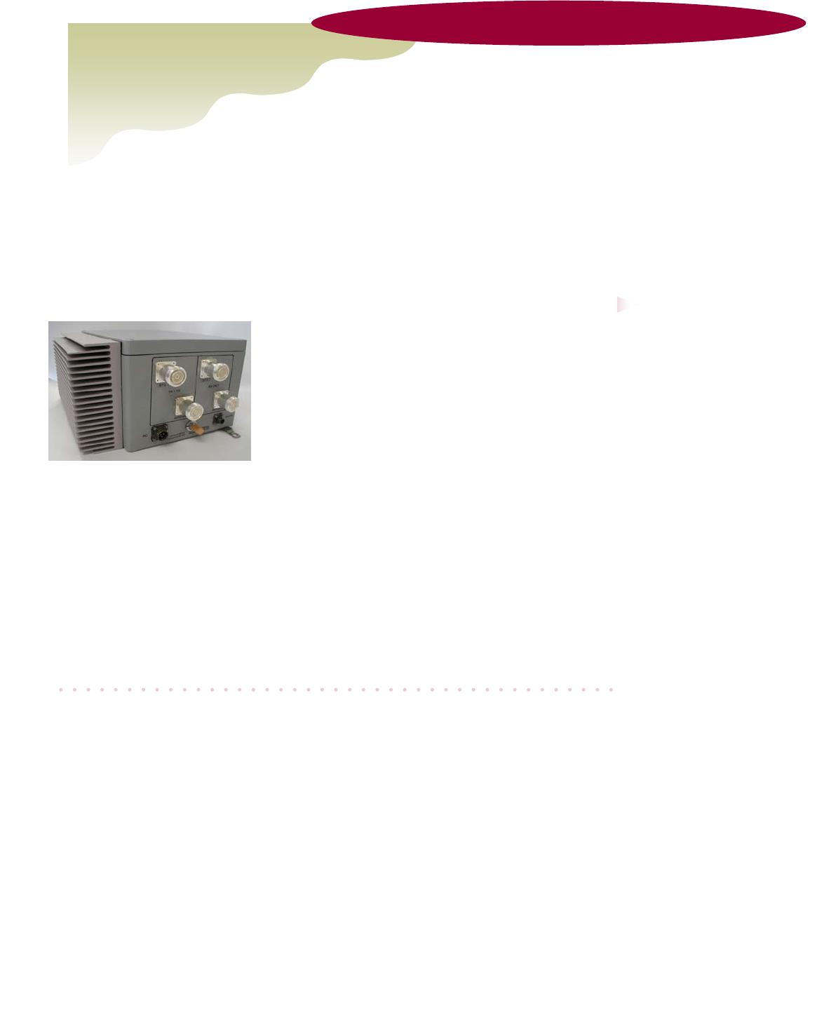
The Cell Extender block consists of a single compact unit with two RF connectors and a single
AC line for power. It is housed in a moisture proof NEMA 4X aluminum die-cast enclosure with
integrated heat sinks and is suitable for either outdoor or indoor installations. The Cell Ex-
tender is designed to boost two pre-combined GSM or EDGE channels that are provided from
the Micro Base Station. It contains redundant low noise amplifiers to boost the receive signals,
redundant LDMOS-based high power amplifiers to boost the transmit signal, dual duplexers,
an integrated power supply and alarm/control circuitry to monitor the operation of the unit. The
Cell Extender is powered by a conventional 110/220 VAC source or can be optionally DC-
powered via the Coax cable using the Remote Power Option.
Options
♦ 01: Additional Rx Only Channel
♦ 02: Monitoring Interface
♦ 03: Remote Power Option (with Internal Bias-T)
♦ AD: A & D Power Operation
♦ B: B Band Operation
♦ C: C Band Operation
♦ EF: E & F Band Operation
Ordering Information
♦ Model CE-1819-10
Communication Components Inc.
Tel: 201-342-3338 Fax: 201-342-3339
FCC Information
A minimum separation distance of 2 meters between the transmit antenna and nearby persons
must be maintained. If this separation distance is not maintained, this device may not be in
compliance with FCC RF Exposure rules.
89 Leuning Street
South Hackensack, NJ 07606
Tel: 201-342-3338
Fax: 201-342-3339
Email: sales@cciproducts.com
Communication Components
Inc.
Www.cciproducts.com
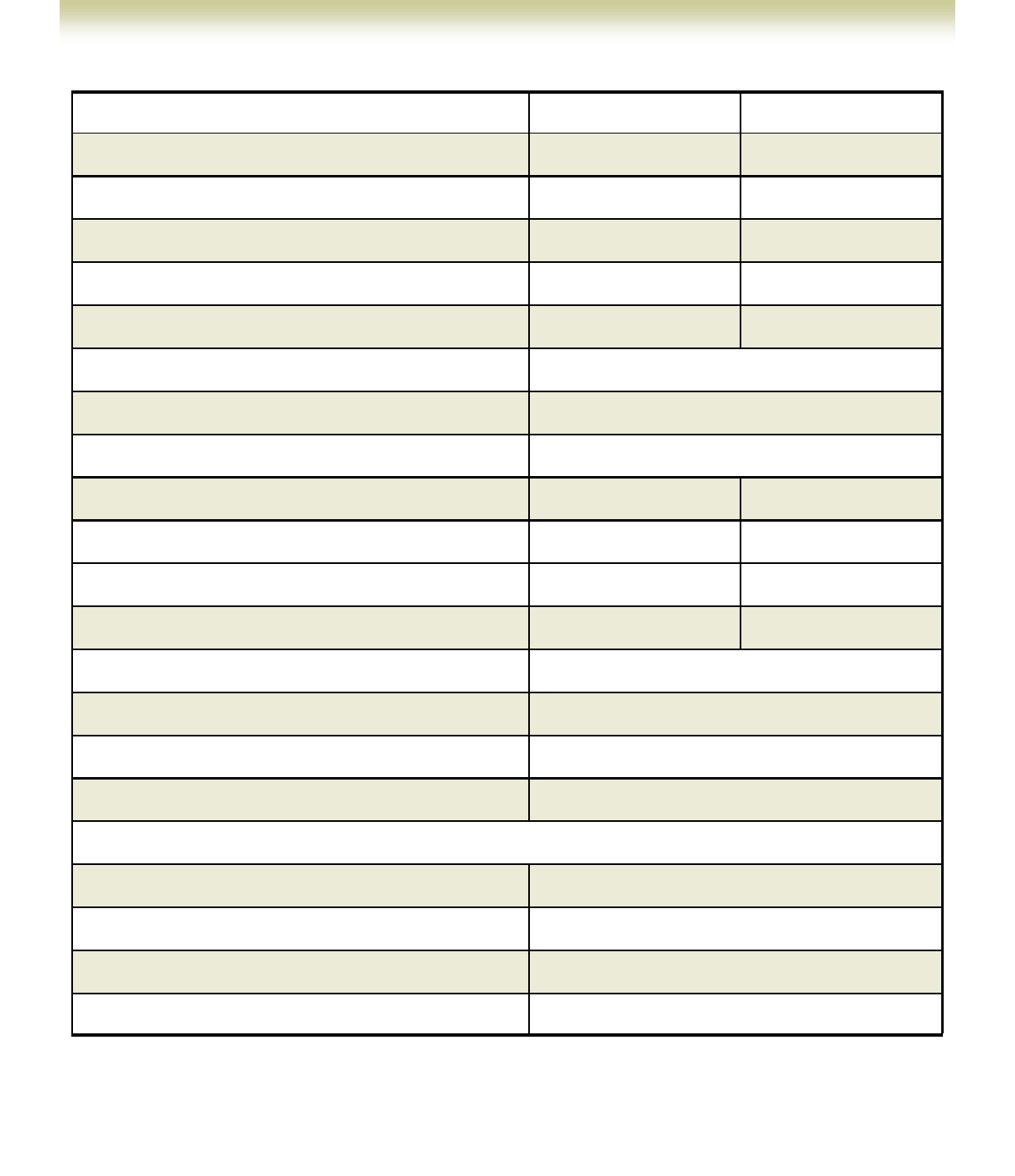
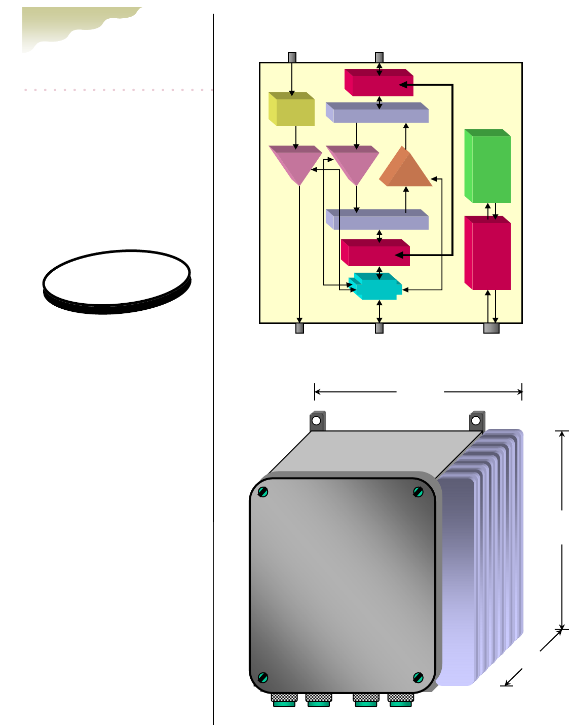
Mechanical Drawing
Block Diagram
Ordering Information:
♦ Model CE-1819-10
♦ 01: Additional Rx Channel
♦ 02: Monitoring Interface
♦ 03: Remote Power Option
(with Internal Bias-T)
♦ AD: A & D Power Operation
♦ B: B Band Operation
♦ C: C Band Operation
♦ EF: E & F Band Operation
Options:
Bypass
Switch
Rx / Tx Duplexer
RX/
Band Pass
Filter
LNA
Power
Amplifier
AC/ DC
Power
Supply
(Optional)
Monitor/
Alarm
(Optional)
ANTENNA
Tx1/ Rx1
Bypass
Switch
Rx / Tx Duplexer
DC
Injector
(Optional)
ANTENNA
Rx2
LNA
(Optional)
BTS
Tx1/ Rx1
BTS
Rx2
AC IN/
ALARM OUT
(Optional)
Tx/Rx1
BTS
Rx2
BTS
10 7/8”
13”
7”
Tx/Rx1
Ant
Rx2
Ant
Communication
Components Inc
CELL EXTENDER
CE-1819-10