Communications MARKII-CII-DMD Power Amplifier User Manual MARKII Kit Instruction Sheet
Communications International Inc. Power Amplifier MARKII Kit Instruction Sheet
Manual

Rev 2.0 6/6/04
If you have determined that the White module (U2 (STM901-30) driving the Final PA has failed…
MARKII kit contains the following:
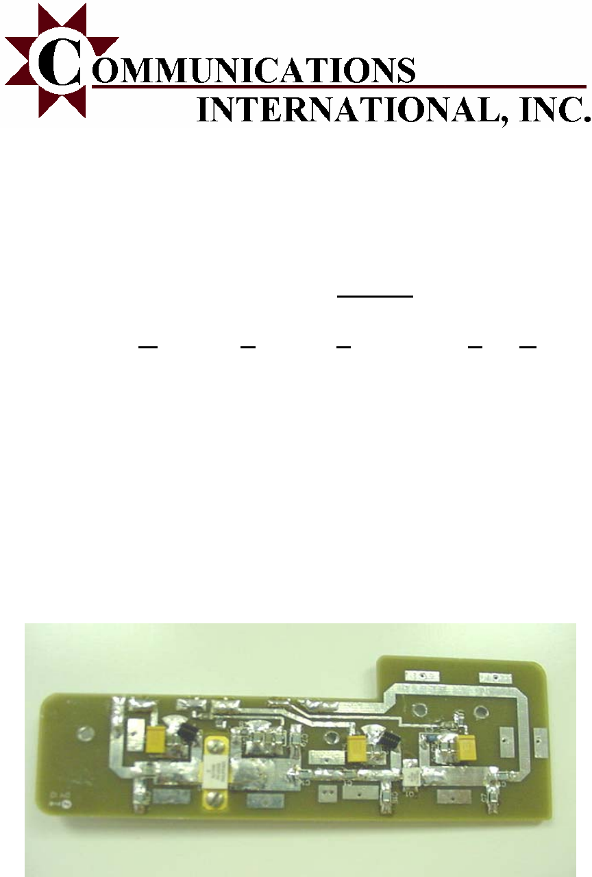
1 1ea PA assembly board
2 1ea Aluminum Spacer w/ four holes
3 4ea 3/16 #4/40 screws (for Q2 on MARK II)
4 2ea ½” #4 metric torq screws (for fastening Mark II Board & Spacer)
5 1ea FCC Label for placement on exterior of PA housing
Please see B3521R3A.pdf or 19D902757G5 Mastr III PA schematic for the proper installation of this
replacement module.
The fan kit 188D6127G1 assembly supplied from MA/Com is required for this module for warranty to
be valid. The PA will exceed heat tolerance & fail without this fan kit.
Disconnect ALL power & control cable from the Mastr III Power Supply
Remove U2 (STM901-30) from Power Amplifier Board A1…being careful to not damage the lands on
the remaining board.
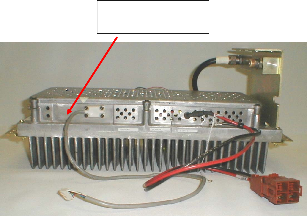
Disconnect P101 from J101. (the small gold connector from the BNC input from the MIII exciter)
This aids in the installation of the MARK II module.
Apply heat sink compound “sparingly” to the bottom of the Aluminum Spacer Plate of the MARKII
RF board. It has been proven that less is better with regards to heat sink compound. Apply only a
slight amount, but sufficient to cover the surface.
Align spacer plate so both holes in the circuit board of the MARK II module align for mounting.
Slowly screw down each side until snug (No more than 1ft/lbs torque).
Place spacer & Module into position where the U2 (STM901-30) module was previously. Mount
assembly using the 4 ea. #4-40 screws. Secure all screws snug (No more than 1ft/lbs torque).
Insert the module under the small hard-line coax P 101 into position & mount using all 4 screws.
Be certain no excessive heat sink compound is across any connections
Solder the 5 connections from the MARK II module to the pins on the Power Amp using proper RF
practice. Stripped Cat5 cable lead cut to about 400 mils can be used to make your leads.
Use the following U2 pin connections with the MARKKII PA.
U2 PIN 12 11 6 5 2 1
MARK II RFout VDD2(A+) VG2 VDD1(A+) VG1 RFin
| | | | | |
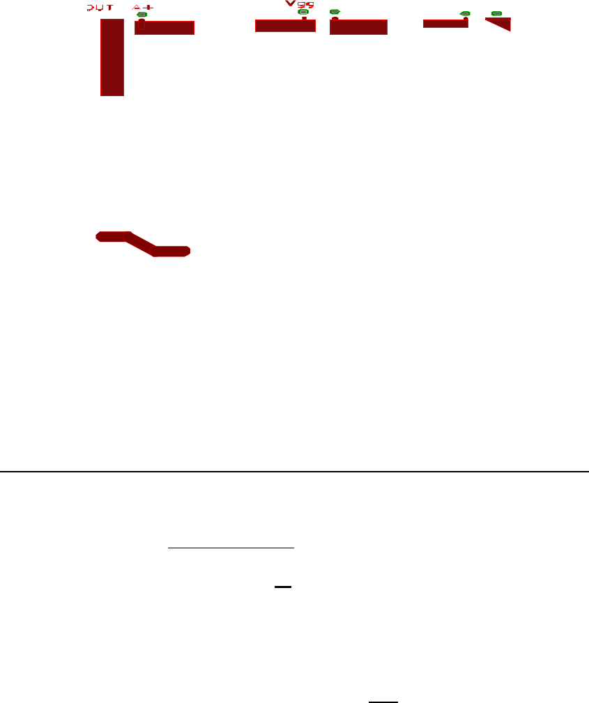
It is suggested to make your pin leads bent on a 45 degree angle and soldered in the following manner
making sure leads which protrude off board do not touch its own ground plane.
Ex.
Rfout(MarkII)
Rfout(G5 Card)
After inspecting that all leads are secure and all flux, etc. is cleaned off board, you are now ready for
testing.
Reconnect P101 to J101
Turn R1, R2, R3, R4, R204, and R48 fully counterclockwise (down approx 20 turns)
(R2, & R3 will now have no effect)
With all power & control cables disconnected & digital ohmmeter negative on ground:
Connect 28VDC supply only (no control or drive cables)
Turn 28VDC supply on (do not transmit yet)
Set Digital power PA pot on Mastr III at 97
Shut off Power Supply & connect all cables from PA to Mastr III
Turn Supply back on
Adjust R48 while monitoring base of Q5 (the Final) to .675 VDC
Now apply PTT (Transmit) (Note: RF Power level is low…This is normal at this point of procedure!)
While monitoring TP1, you should not have any control voltage.
While PTT is on, slowly adjust R204 clockwise until a voltage appears on TP1 (about 0.200 VDC).
Now, you have activated the knee voltage on the 22Volt regulator switch. This is needed to bias up the
transistors with small signal conditions to settle in without a load, since LDMOS is very sensitive to
break in voltage.
Adjust R1 slowly (over at least a 20 second period) to 4.7VDC (approx 10 turns)
Adjust R4 slowly (over at least a 20 second period) to 4.8VDC (approx 10 turns)
Adjust R204 to approx 11 Amps or 100 watts while monitoring current and power.
At this point, the amp is ready to be fielded. Place cover back on unit and remember, any digital pot
setting above 95 will yield upward of 120 Watts and is not recommended nor warrentied if users go
above 100 Watts of operation.
Installation of Identifying Label
FCC and Industry Canada Regulations require the installation of the label provided prior to operating
the unit.
Unit is ready for operation.
Communications International, Inc.
Mark II Upgrade Kit
FCC ID: SA8MARKII-CII-DMD
IC ID: 5363A-MARKIICA
6/3/2004
Pricing of the Mark II PA module
Master III Amplifier Replacement Kit - II stage
1. Mark II - 1-9 unit price ……………………………... $495
2. Mark II - 10 units or above ………………………….. $450
3. Mark II installed in your PA ………………………… $795
4. Mark II installed in your PA with other problems … $1495
(may include replacement with entire amplifier)
Warranty Information:
CII offers the following warranty on the options above.

Option 1,2:
90 day warranty on parts and materials only. Each module sold from CII has been inspected, tested
and burned in to produce 100 Watts before leaving the factory. CII only recommends this option to
experienced communication houses who have the proper resources and experienced personnel to
perform installation and test.
However, if our module fails to operate during a customer installation, CII will request the customer
ship back the MARK-II PA board for diagnostics to determine the problem and recommend a fix on a
case by case basis.
Option 3: 90 day warranty parts and labor. Shipping responsibility of customer.
Option 4: 90 day warranty parts and labor. Shipping responsibility of customer.
This Mark II Upgrade Kit complies with Part 90 of the FCC Rules and Regulations and Spectrum
Management and Telecommunications Policy RSS-119 of Industry Canada.
FCC ID: SA8MARKII-CII-DMD
IC ID: 5363A-MARKIICA
WARNING! Changes or modifications not expressly approved by the manufacture could void the
user's authority to operate the equipment.