Companion 315241940 User Manual MITER SAW Manuals And Guides L0501035
COMPANION Miter Saw Manual L0501035 COMPANION Miter Saw Owner's Manual, COMPANION Miter Saw installation guides
User Manual: Companion 315241940 315241940 COMPANION MITER SAW - Manuals and Guides View the owners manual for your COMPANION MITER SAW #315241940. Home:Tool Parts:Companion Parts:Companion MITER SAW Manual
Open the PDF directly: View PDF ![]() .
.
Page Count: 30

OPERATOR'S MANUAL
4
10 in. COMPOUND MITER SAW
Model No.
315.241940
WARNING: To reduce the risk of
iniury, the usermust read and under-
stand the operator'smanuatbefore
usingthis product,
Customer Hetp Line: 1-800-932-3188
Sears, Roebuck and Co., Hoffman Estates, IL 60179 USA
Visit the Craftsman web page: www.sears.com/craftsman
983000-437
3-04
Save this manual for future reference

•Warrantyand introduction................................................................................................................................................. 2
•General Safety Rules..................................................................................................................................................... 3-4
• Specific Safety Rules..................................................................................................................................................... 4-5
•Symbols......................................................................................................................................................................... 6-7
•Electrical............................................................................................................................................................................ 8
•Glossary ofTerms.............................................................................................................................................................. g
•Features..................................................................................................................................................................... 10-12
•ToolsNeeded ................................................................................................................................................................. 12
•Loose Parts .................................................................................................................................................................... 13
•Assembly................................................................................................................................................................... 13-20
•Operation................................................................................................................................................................... 20-26
•Adjustments.............................................................................................................................................................. 27-28
• Maintenance................................................................................................................................................................... 29
•Parts Ordering/Service................................................................................................................................................... 30
ONE YEAR FULL WARRANTY ON COMPANION TOOL
If this Companiontool failsdue to a defect inmaterial orworkmanshipwithin one year fromthe date of purchase,
RETURN IT TO THE NEARF__TSEARS STORE IN THE UNITED ffrATE8, and Sears will replace it, free of charge.
This warranty is void if thistool is used for commercialorrental purposes.
This warranty givesyou specific legal rights,and you may also have other rightswhich vary fromstate to state.
Sears, Roebuck and Co., Dept. 8t7 WA, Hoffmen Eatates, IL 60179
This tool has many featuresformaking its use more pteas_ntand enjoyable. Safety, performance,end dependability
have been given top pr)oriL'yinthe designof thisproduct making )t easyto maintainand operate.
2

,_ WARNING: Read and understand all inatrucl
tlone. Failureto followall inst_'uctionslisted below,
may rssuttin etecLricshock, fire and/or serious
persona_iniury.
READ ALL iNSTRUCTIONS
•KNOW YOUR POWER TOOL. Read the operator's
manual carefully.Learnthe eawls applicationsand limi-
tations as well as the specific potential hazardsrelated
to thistool.
• GUARD AGAINST ELECTRICAL SHOCK BY PRE-
VENTING BODY CONTACT WITH GROUNDED
SURFACES. For examp]e, pipes, radiators,ranges,
refrigeratorenclosures.
• KEEP GUARDS IN PLACE and In goodworking order.
•REMOVE ADJUSTING KEYS AND WRENCHES.
Form habit of checkingto see that keys and adjusting
wrenches are removed frpm tool before turningit on.
•KEEP WORK AREA CLEAN. Cluttered areas and
benchesinvite _ccidenta.00 NOT _aavetoolsor
piscesof wood on the saw whila It is in operation.
•DO NOT USE IN DANGEROUS ENVIRONMENTS.
Do not usa power tools in damp or wet focations or
expose to rain.Keep the work areawell tit.
•KEEP CHILDREN AND VISITORS AWAY.All visitors
shouldwear safety glassesand be kept a safe dLs-
lance fromwork area. Do notlet visitorscontact tool or
extensioncord white operating.
•MAKEWORKSHOPCHILDPROOFwith padlock.sand
master switches, or by removingsLarterkeys.
• DON'T FORCE TOOL. [t will do the job better and
eater at the feed rate for which it was designed.
•USE RIGHT TOOL. Don't force the tool orattachment
to do aiob it was not designed for. Don't use Rfor a
purpose not intended.
•USE THE PROPER EXTENSION CORD. Make sure
your extensioncord is ingood condition.Use only a
cord heavy enoughto carrythe currentyour product
will draw. An undersizedcord will cause a drop In line
voltage resultingin lossof power and overheating.A
wire gauge size (A.W.G.)of at least 14 is recommended
for an extensioncord 25 feet or less in length. If in
doubt, use the next heavier gauge.The smallerthe
gauge number,the heavierthe cord.
•DRESS PROPERLY. Do not wear loose clothing,
gloves,neckties, or jewelry.They can get caught
and drawyou into moving parts. Rubber glovesand
nonskid footwear are recommended when working
outdoors.Alsowear protectiveha'rrcoveringto contain
long hair.
•ALWAYSWEAR SAFETY GI.ASSEB WITH SIDE
SHIELDS. Everydayeyeglasseshave only impact-
resistantlenses, they are NOT satety glassas.
•SECURE WORK. Use clampsor a vise to hold work
when practical. It's saferthan usingyour hand and
|rees both hands to operate tool
•DON'T OVERREACH. Keep proper footingand bah
ance at all times.
•MAINTAIN TOOLS WITH CARE. Keep toolssharp and
cleanfor better and safer performance.Follow instruc-
tionsfor lubricating and changingaccessories.
•DISCONNECT TOOLS. When not inuse, before ser-
vicing,or when changingattachments,blades, bits,
cutters, etc., all tools shouldbe disconnected.
•AVOID ACCIDENTAL STARTING. Be sureswitch is off
when pluggingin anytool.
•USE RECOMMENDED ACCESSORIES. The use of
improper accessories may riskinjury.
•NEVER STAND ON TOOL, Seriousinjury could occur
if the tool istipped or if the cutting tool is unintention-
ally contacted.
•CHECK DAMAREO PARTS. _fore furtherLLSeOf
the tOO[,a guardor other pert that is dsmeged should
be carefullychecked to determine that it willoperate
properlyand performits intended function.Check for
alignment of moving pe_Ls,binding of moving parts,
breakage of parts, mounting and any ot_er conditions
that may aff'ecf:its operation.A guardor other part that
is damaged must be properlyrepaired or replacedby
an authorized service centertoavoid risk of personal
injury.
•USE THE RIGHT DIRECTION OF FEED. Feed work
into a blade or cutter againstthe directionof rotation of
blade or cutter only.
• NEVER LEAVE TOOL RUNNING UNATrENDED,
TURN THE POWER OFR Don't leave tool untilit
comes to a complete stop.
II PROTECT YOUR LUNGS. Weara face ordust mask if
the cuttingoperationis dusty.
•PROTECT YOUR HEARING. Wear hearingprotection
duringsxtandsd periodsof operation.
• DO NOT ABUSE CORD. Never yank cord to discon-
nect from receptacle.Keep cord from heat, oil,and
sharp edges.
•USE OUTDOOR EXTENSION CORDS. When 'Lociis
uead outdoors,usa onlyextensioncordswith ap-
provedgroundconnectionthat are intendedfor use
outdoorsand so marked.
•KEEP BLADES CLEAN, SHARP, AND
WTTH SUFFICIENT SET. Sharp blades minimizestalll
ing and kickback.
•BLADE COASTS AFTER BEING TURNEDOFR
•NEVER USE IN AN EXPLOSNE ATMOSPHERE.
Normal sparkingof the motor could ignite fumes.
3

•INSPECT TOOL CORDS PERIODICALLY. If damaged,
have repaired by a qus_od sarvicat_.hn_lan at _n
authorizedservicefae){ity.The conductor with insula-
tion having an outer surface that is green with or with-
out yellow eVipse isthe equipment-groundingconduc-
tor. If repairor replacementof the electric cord or plug
is necessary,do not connect the equipment-grounding
conductorto a[[ve terminal Repair orreplace adam-
aged or worn cord immediately.Stay constantlyaware
of cord location and keep it well away from the rotating
b_da.
• INSPECT EXTENSION CORDS PERIODICALLY and
replace if damaged.
•KEEP TOOL DRY, CLEAN, AND FREE FROM OIL
AND GREASE. Always use a dean c_othwhen clean-
ing. Never use brake fluids, gasoline,petroleum-based
products, orany solvents to clean tool
• STAY ALERT AND EXERCISE CONTROL, Watch
what you are doing and use common sense. Do not
operate too{when you are tired. Do not rush.
• DO NOT USE TOOL IF SWITCH DOES NOT TURN IT
ON AND OFF. Have defectiveswitchesreplaced by an
authorizedservice center.
•USE ONLY CORRECT BLADES. Do not use b{ades
with incorrectsize hoise.Never use blade washers or
b_de bolta that are defective or {nCOTT_"_."[hemBx_-
mum b%adaeapad_ of your saw Is 10 in. (254 ram).
•BEFORE MAKING ACUT, BE SURE ALL ADJUST-
MENTS ARE SECURE.
•BE SURE BLADE PATH IS FREE OF NAILS. Inspect
for and remove atfna_sfrom lumber before cutting.
•NEVER TOUCH BLADE orother moving partsduring
UaS.
•NEVER STARTATOOLWHEN ANY ROTATING COM-
PONENT IS IN CONTACT WITH THE WORKP|ECE.
•DO NOT OPERATE A TOOL WHILE UNDER THE
INFLUENCE OF DRUGS, ALCOHOL, OR AI_Y
MEDICATION.
•WHEN SERVICING use only identic_ replacement
parts. Use of any other pads may create a hazard or
cause productdarr_ge.
•CHECKWITH AQUALIFIED ELECTRICIAN or service
personnelJfthe groundinginstructionsare not com-
pletely understoodor it indoubt as to whether the toot
LSproperlygrounded.
•USE ONLY RECOMMENDED ACCESSORIES listed
in this manual or addendums. Use of accessories
that are not listed may cause the risk of personal
injury.Instructions for safe use of accessories are
included with the accessory.
•DOUBLE CHECK ALL SETUPS, Make sure blade is
tight and not making contact w)th saw or workpiece
before connecting to power supply,
•FIRMLY CLAMP OR BOLT your miter sew to a work- •
bench or table at approximatelyhip height.
•KEEP HANDS AWAY FROM CUTrlNG AREA. Do not
reach underneath wor!<or in blade cuttingpath wlth
your hands and fingersfar any reason.Alwaysturn the
power off.
•ALWAYS SUPPORT LONG WORKIPIECES while cut-
ting to minimizeriskof blade pinchingand kloid0aok. •
Saw mayslip, walk or slide while cutting long orheavy
boards.
• ALWAYS USE A CLAMP to secure the workplece
when possible.
•BE SURE THE BLADE CLEARS THE WORKPIECE.
Neverstart the sewwith the bladetouchingthe
wcrkpiece. Allow motor to come up to full speed
before startingcut.
•MAKE SURE THE MITER TABLE AND SAW ARM
(BEVEL FUNCTION) ARE LOCKED IN POSITION
BEFORE OPERATING YOUR SAW. Lock the miter
table by securelytightening the miter lock levers. Lock
the saw arm (bevelfunction}by securely tighteningthe
bevel lockknob.
NEVER USE A LENGTH STOP ON THE FREE SCRAP
END OF A CLAMPED WORKPIECE. NEVER hold
onto orbind the free scrap end of the workplace in any
operat'_r_. If =_work clamp and length stopare used
together,they must both be installedon the same side
of the sew _ablato preventthe sew from catchingthe
loose end and kickingup.
NEVER out more than one piece at a time. DO NOT
STACK more than oneworkpiece on the saw table at a
time.
NEVER PERFORM ANY OPERATION FREEHAND.
Alwaysplacethe workpJeceto be cut on the miter
table and positionit f'_mlyagainst the fence ase back-
stop. Alwaysuse the fence.
NEVER hand holda workpieoethat is too smallto be
clamped. Keep hands riser of the cutting arcs.
NEVER reachbehind, under,orwithin three inches
of the blade and its cuttingpath w_h yourhands and
fingersfor any reason.
•NEVER reach to pick up aworkpiece, a piece of scrap,
or anything e_ss that is in or near the cutting path of the
b_de,
•AVOID AWKWARD OPERATIONS AND HAND PO-
SITIONS where asudden slip couldcause your hand
to move intothe blade. ALWAYS make sure you have
good balance. NEVER operate yourmiter saw onthe
flooror in acrouched position.
•NEVER stand or haveany part of yourbody in line wfth
the path of the saw blade.
•ALWAY8 releasethe power switch and allow the
saw blade to stop rotating beforeraising it out of the
workpiece.
•DO NOT TURN THE MOTOR SWITCH ON AND OFF
RAPIDLY. "l%hiscou(d cause the saw blade to loosen
and could create a hazard. Shouldthis ever occur,
stand cTserand at_owthe saw blade to come to s com-
plete stop. Disconnectyour saw from the power supply
and socurolyretightenthe blade bolt.
•IF ANY PART OF THIS MITER SAW IS MISBING or
should break, band, orfail in anyway, or shouldany
electricalcomponent fail to perform properly,shut off
the power switch, remove the miter saw plug(Tomthe
power sourceand have damaged, missing, or failed
parts replaced before resumingoperation.
•ALWAYSSTAY ALERT] Do not allow familiarity (gained
from frequentuse of your saw)to seuse acareless
mistake. ALWAYS REMEMBER that a carelessfraction
of a second is sufficientto inflictsevere injury.
•MAKESURETHEWORKAREAHASAMPLE LIGHT-
ING to see the work andthat no obstructionswit] inter-
tara with saf_ oper-tion BEFORE psrtorr_in(.} any work
usingyour saw.
•ALWAYSTURN OFF THE SAW before disconnecting
it to avoid accidentalstartingwhen reconnectingto
power suppty.NEVER leave the saw unattendedwhile
connected to apowersource.
•THIS TOOL should have the following markings:
a) Wear eye protection.
b) Keep hands out of path of saw blade
c) Do not operate saw withoutguardsin pJaos.
d) Do not perform any operation freehand.
e) Never reach aroundsew b{ade.
f) Turnoff tool and walt for saw blade to stop before
moving work.pieceor chang(rigsettings.
g) Disconnectpower (or unplugtool as applicab{e)
before changingblade or servicing.
h) No load speed.
•ALWAYS carrythe tool only by the carrying handle.
•SAVE THESE INSTRUCTIONS, Referto them
frequently and use to instructother usem.If you loan
someonethistool, loan them thess instructionsalso.
WARNING: S(xr_ dust created by power sand{ng,sawing, gr(nding, drii{(ng, end other construction_ctNitiea con-
tains chemicals known to cause cancer, birthdefects orother reproductiveharm. Some examples of these chem-
icalsare:
• leadfrom lead-based paints,
•crystallinesilica from bricksand cement and other masonry products,and
• arsenic and chromium fromchemically-treated {umber.
Yourrisk(Tomthese exposures varies, dependingon how oftenyou do thistype of work. Toreduce your exposure
to these chemicals: work inawell ventilatedarea, and work with approved safety equipment,suchas those dust
masks that are speciallydesignedto filter out microscopicparticles.
5

Someof the followingsymbols may be used on this tool. Please study them and learn their meaning. Proper
interpretation of these symbolswill allow you to operate the tool betterand s,_fsr.
SYMBOL NAME OESIQNATION/EXPLANATIO N
V Volts Voltage
A Amperes Current
Hz Hertz Frequency(cyclesper second)
W Watt Power
rain Minutes Time
Aitemeting Current Type of current
•- DirectCurrent Type or a characteristicof current
no No Load Speed Rotationalspeed, at notoad
[] ClassII Construction Daub[s-insulatedconstruction
..Jmin Per.Minute Revolutions,stTokes,surface speed, orbitsetc., per minute
Wet ConditionsAJert Do notexpose to rain or use in damp locations.
Read The Operator's Manual Toreduce the riskof injury,usermust read and understand
operator's manual before usingthis product.
Protection Atwayswear safety gogglesor safety glasseswith side
Eye shieldsand a fullface shieldwhen operatingthis product.
Safety Atert Precautionsthat involveyour safety.
Failureto keep your hands away from the blade will rseu_tin
No Hands Symbo_ seriouspersonatinjury.
(_ Failureto keep yourhands away from the blade w_l result_n
No Hands Symbol serious persona{injury,
eFailureto keep your hands away fromthe bladewill resultin
No Hands Symbol seriouspersona{injury.
No Hands Symbol Failureto keep y_ur hands away fromthe blade wi{{result in
seriouspersona_in,P/.
(_ Ho'_Surface To reducethe riskof {niuryordt_'_age, avoid contactw_th
any hot surface.
6
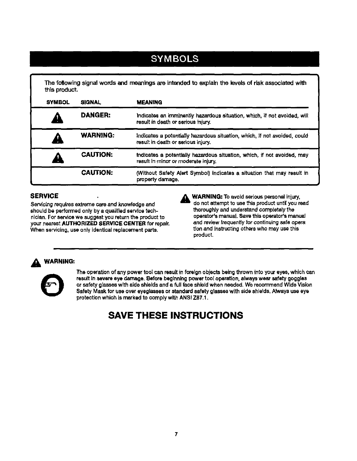
The following signal words and meanings are intended to explain the levels of risk associated with
this product.
SYMBOL SIGNAL MEANING
A DANGER: Indica.tssan imrninantlyil_.ardous situation,which, if not avoided, will
result in death orseriousfniury.
WARNING: Indicates a potentiallyhazardoussituation,which, if not avoided, could
resultin death or seriousinjury,
CAUTION:
CAUTION:
Indicates a potentially hazardoussituation,which, ifnot avoided, may
result inminor ormoderate injury.
_/ithout Safety Alert Symbol) Indicates asitus,tion that may result in
propertydamage.
SERVICE
Servicingrequiresextreme care and knowledgeand
should be performed only by a qualifiedservice tech-
nician. For servicewe suggest you returnthe productto
your nearestAUTHORIZED SERVICE CENTER for repair.
When servicing,use only identicalreplacementparts.
WARNING: To avoid seriouspersonalinjury,
do not attempt to use thisproduct untilyou read
thoroughlyand understandcomptetalythe
operator'smanual.Save this operators manual
and review frequently for continuingsafe opera
tfonand Ins_'uctingotherswho may usethis
product,
&WARNING:
OThe operationof any power tool can resultin foreign objects beingthrowninto your eyes, which can
result in severe eye damage, Before beginningpower too[ operation,always wear safetygoggles
or safety g[aseeswlth side shieldsand a fullface shieldwhen needed.We reoommendWide Vision
Safety Mask for use over eyeglasses or standard safety glasseswith side shields.Alwaysuse eye
protectionwhich is marked to complywith ANSI Z87.1.
SAVE THESE INSTRUCTIONS
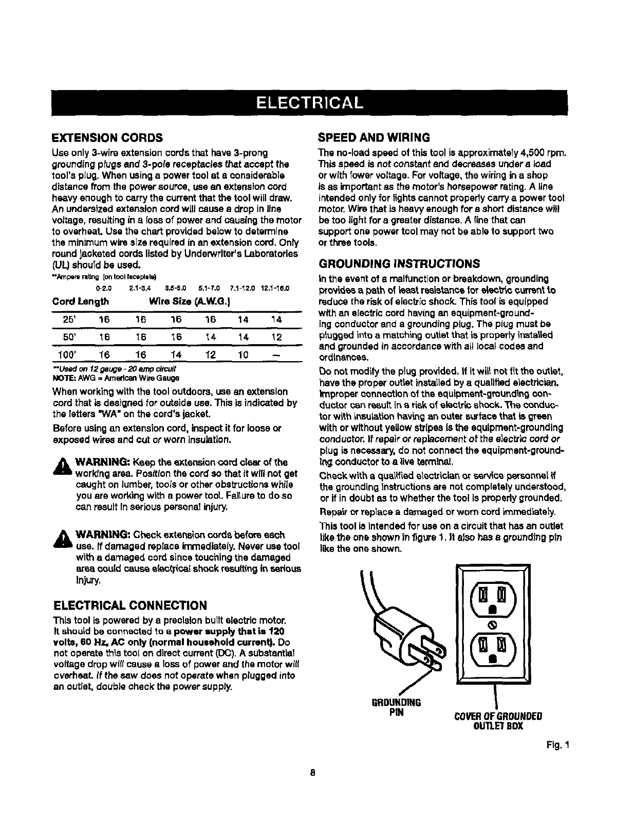
EXTENSION CORDS
Use only 3-wire extensioncords that have 3-prong
groundingplugsand 3-pole receptaclesthat accept the
tool's plug. When usinga power tool at s considerable
distance from the powersource, use an extensioncord
heavy enough to carrythe currentthat the tool will draw.
An undersized extensioncord will causea drop in line
voltage, resultingina foes of powerand causingthe motor
to overheat.Use the chart providedbelow to determine
the minimumwire size requiredin an extensioncord. Only
round Jacketedcords listed by Underwriter'sLaboratories
(UL)shouldbe used.
-Ampe_ rating (ontool facep!ete)
0-2.0 2.%3,4 3,5-5.0 5.1-7,0 7.%_ 2.0 12,1-'{0,0
Cord Length Wire Size (A.W.G.)
25' 16 16 16 16 14 14
50' 16 16 _6 _4 14 12
100' 16 16 14 12 10 --
--Ueed on12 gauge -20 amp circuit
NO'RE:AWG = Amedcan Wire Gauge
When working with the tool outdoors, use an extension
cord that is designed for outside use.This is indicated by
the letters"WA" on the cord's jacket.
Before using an extensioncord. inspect it for loose or
exposed wiresand cut or worn insulation.
A WARNING: Keep the extension cord clearof the
workrngarea. Positionthe cord so that it wiflnot get
caught on lumber,tools or other obstructionswhile
youare workingwith a power tool.Failureto doso
can result fnseriouspersonal injury.
WARNING: Check extensioncords before each
use. If damaged replace immediately.Never use tool
with adamaged cordsince touchingthe damaged
are_ cou(d cause s(oc_cat shock resu(tinginserious
Injury.
ELECTRICAL CONNECTION
This tool is poweredby aprecisionbuiltelectric motor.
It should be connected to a power supply that is t20
volts, 60 Nz, AC only (normal household current). Do
not operate this toot on direct current(DC). A substantial
voltage dropwilt cause a lossof power and the motor wltl
overheat,If the saw does notoperate when pluggedinto
an outlet,double check the power supply.
SPEED AND WIRING
The no-load speed of thistool is approximately4,500 rpm.
7his speed is not constant and decreasesundera Iced
or with fewer voltage. Forvoltage, the widng ina shop
is as importantas the motor'shorsepowerrating.A line
intendedonly for lightscannot properlycarryapower tool
motor.Wire that is heavy enoughfor a short distancewill
be too lightfor a greater distance.A finethat can
support one power tool may not be able to support two
or three tools.
GROUNDING INSTRUCTIONS
in the event of a malfunctionor breakdown,grounding
provides _ pathof k_astresistancefor electriccurrentto
reduce the riskof electricshock. This tool is equipped
with an electric cord having an equipment-ground-
ing conductorand a groundingplug. The plug must be
plugged intoa matchingoutletthat is properlyinstalled
and grounded inaccordancewith all local codesand
ordinances.
Do notmodify the plu9 provided. If it winnotfit the outlet,
have the proper outlet installedby aqualifiedelectrician.
improper connectionof the equipment-groundingcon-
ductor can re,sultinariskof eiectr_ shock. The cond_,-
tor with insulation hav_ngan outer surface that is green
with orwithout yellow sffipesis the equipment-grounding
conductor.)f repairor replacementof the electriccord or
plugis necessary,do notconnect the equipment-ground-
ing conductorto alive tarmlna}.
Check with aqualified electrician _r ser_ce persone_elif
the groundinginstructionsare notcompletely understood,
or if indoubt as to whether the tool Is properlygrounded.
Repairor replace a damaged orworn cord immediately.
This tool is intendedfor use on a circuitthat hasan outlet
likethe one shown infigure 1, It else has s groundingpin
likethe one shown.
GBDUNDING I
PIN COVEROFGROUNDED
OUTLETBOX
Fig. 1
8
Anti-Kickback Pawls (radial arm and table saws)
A dev?sewhich,when property ?nste]ladand maintained,
is designed to stop the workplace from being kioked back
toward the front of the saw duringarippingoperation.
Arbor
The shaft onwhich ablade or cutting tool is mounted,
Bevel Cut
A cuttingoperationmade with the blade atany angle
otherthan 90" to the table surface.
Chamfer
A cut removingawedge from• block so the end (or part
of the end) is angled ratherthan at 90°.
Compound Cut
A crosscut made with both emiterend abevel angle.
Crosscut
A cuttingor shaping operationmade acrossthe grainor
the width of the workpieee.
Cutter Head (Planers and Io/ntera|
A rotating plaoe of adiustablablades.The cutter heed
removesmaterialfrom the workplece.
Dedo Cut
A non-throughcut which producese squara-sJdsdnotch
or hough inthe work,piece (requiresaepsolai blade).
Featherboard
A device used to help centre] the workpJecaby guiding Jt
securelyagainst the table or fence duringany ripping
operation.
FPM or SPM
Feet per minute (orstrokes perminute),used in reference
to blade movement.
Freehand
Performingacut without the workplacebeing guided by a
fence, mitergauge, or other aids.
Gum
A sticky,esp-bassd residuefrom wood products,
Heel
Alignmentof theblade to thefence.
Kerr
The material removed by the blade inathroughout orthe
slot producedby the blade in a non-through or pertlalcut.
Klckback
A hazard that can occur when the blade bindsor stalls,
throwingthe workpleoe back towerd operator.
Leedlng End
The end of the workpieoe pushed intothe tool first.
Miter Cut
A cuttingoperationmade with the workp?eoeat any angle
to the blade other than 90°,
Non-Through Cuts
Any cuttingoperationwhere the blade does not extend
completelythroughthe thickness of the workpiecs.
Push Blocks and Push Sticks
Devicesused to feed the work:piecethroughthe saw
blade duringcuttingoperations.A push stick (nota push
block)shouldbe used for narrowrippingoperations.
These aids help keep the operator'shands well away from
the blade.
Pilot Hole (drill presses]
A small hole drilledina workpiecethat serves as a guide
for drillinglarge holes accurately.
Ra_w¢
Acuttingoperationto reduce the thickness of the work-
piece to make thinnerpieces,
Resin
A sticky,eep-based substanoethat hashardened.
Ravoful_tonsPar Minute (RPM)
The numberof turnscompleted by a spinning object in
one minute.
Ripping or Rip Cut
A cuttingoperationalong the lengthof the workplace.
Riving Knife (table saws)
Also known as a spreaderor splitter. A metal piece,
slightlythinnerthan the sew blade,which helps keep the
kerr open and also helpsto preventkickback.
_v Blade Path
The area over, under,behind,or in front of the blade. As
it appliesto the wcrkpiece, that areawhich will be or has
been cut by the blade.
Set
The distance that the tip of the saw blade tooth is bent (or
set) outwardfrom the face of the blade.
Snips (planers}
DeprassJonmade at either end of s workplace by cutter
bladeswhen the workpiece is not properlysupported.
Throw-Beck
The throwingback of a workpiece usuallycaused by the
wcrkplacs being droppedinto the blade or being placed
inadvertentlyincontact with the blade.
Through Sawing
Any cuttingoperationwhere the blade extends completely
through the thickness of the wcrkpleca.
Work.piece or Material
The item on which the operationis beingdone.
Worktable
Surfacewhere the workpiece rests while perforatinga
cutting,drilling,planing,or sandingoperation.
g
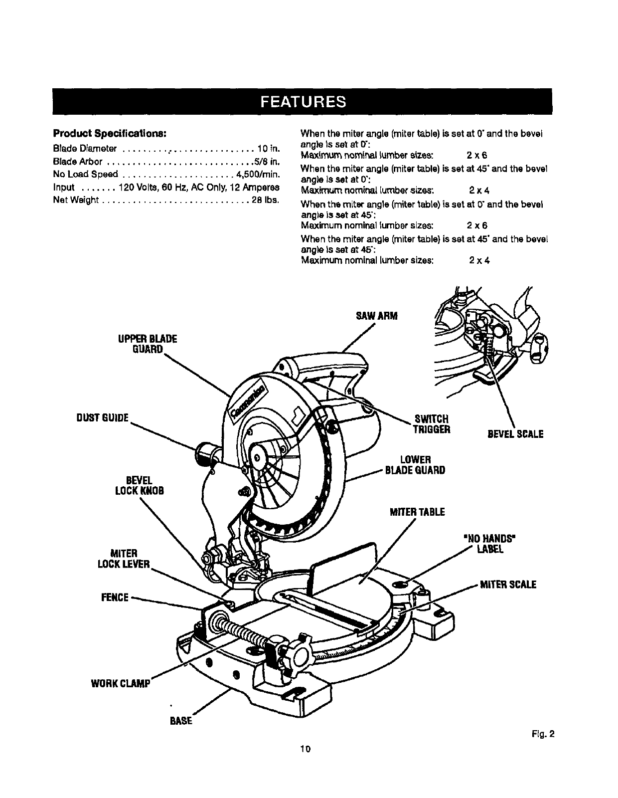
Product Specifications:
Blade Diameter ......... • ................ 10 in.
Blade Arbor ............................. 5/8 in.
No Load Speed ...................... 4,500/min.
Input ....... 120 Volts, 60 Hz, AC Only,12 Amperes
Net Weight ............................. 28 Ibs.
When the miterangle (mitert_ble) is set at O"and the bevel
angle is set at 0":
Maximum nomir_l Lumbersizes: 2 x 6
When the miter angle (miterta.ble)isset at 45"and the bevel
angle is set at 0":
Maximum nomir_i lumber sizes: 2 x 4
When the miter angle (mitertable) is set at O"and the bevel
ang)eis set at 45":
Maximum nominallumbersizes: 2 x 6
When the miter angle (mitertable) is set at 45"and the bevel
angle is set at 45":
Maximum nominallumber sizes: 2x 4.
UPPERBLADE
GUARD
SAWARM
DUETGUIDE
BEVEL
LOCKKNOB
LOWER
MITERTABLE
BEVELB_LE
MITER
LOCKLEVER
WORKCLAMP
Fig. 2
10
KNOWYOURCOMPOUNDMITERSAW
See Figure2.
Before attemptingto use this product,familiarize your-
self with elf operatingfeatures and safety requfrements.
t2 AMP MOTOR
Your saw has a powerful 12 amp motor with sufficient
power to handle tough cuttingjobs. It is made withall
bah bearings,and has externallyaccessible brushesfor
ease of servicing.
10 in. BLADE
A 10 in.saw blade is included withyour compound
miter saw. )twill cut materialsup to 2 in. thick or6 in.
wide, depending upon the angleat which the outis be-
ing made.
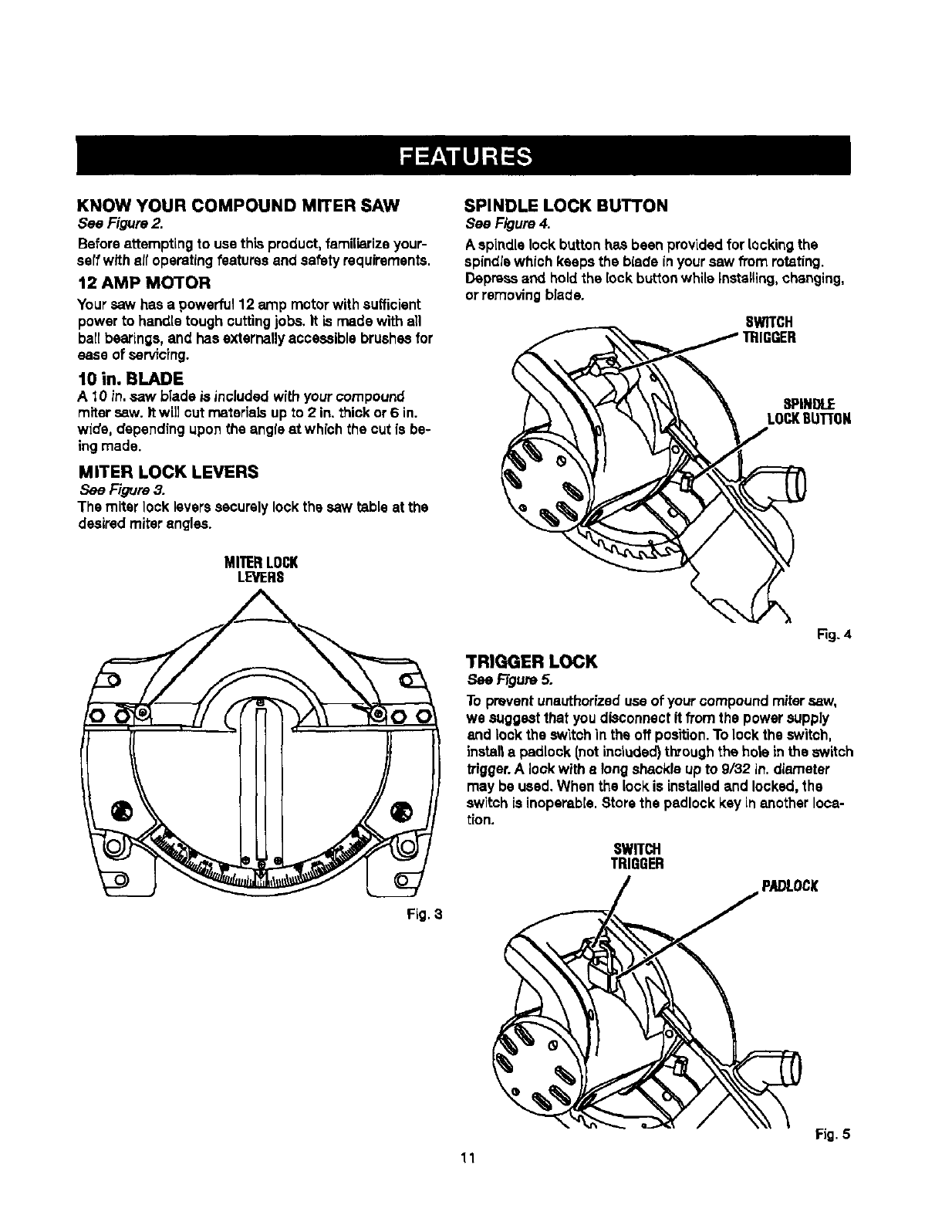
MITER LOCK LEVERS
See Figure 3.
The miter lock leverssecurelylock the saw table at the
desiredmiter angles.
MITERLOCK
LEVERS
SPINDLE LOCK BUTTON
See Figure 4.
A spindle lock button has been providedfor lockingthe
spindle which keeps the blade inyour saw from rotating.
Depress and holdthe lock buttonwhile Installing, changing,
or removingblade.
SWITCH
TRIGGER
8PINOLE
LOCKBU1]'ON
Fig. 3
Fig. 4
TRIGGER LOCK
See FTgum5.
To preventunauthorizeduseof your oompound mitersaw,
we suggest that youdisconnect it from the power supply
and lockthe switchin the off position.To lock the switch,
installa padlock (notincluded)throughthe hole inthe switch
trigger.A lookwith elongshackle upto 9/32 in. diameter
may be used. When the lock is installedand locked,the
switch is inoperable.Store the padlock key in another loca-
tion.
SWITCH
TRIGGER
PADLOCK
Fig.5
11
WARNING:Theoperationofany saw can result
inforeign objects beingthrown into your eyes,
which can result in severe eye damage. Before
stating power tool operation, always wear safety
goggles or safety giaeseswith side shieidsand
afull face shieldwhen needed. We recommend
wide visionsafety mask for use overeyeglassesor
standardsafety glasseswithside shields.
BEVEL LOCK KNOB
The bevel lock knob securelylocks yourcompound
miter saw at desiredbevel angles.A positivestopad-
justment screw has been providedon each side of the
saw arm. These adiustment screws are for making fine
adjustmentsat 0"and 45".
ELECTRIC BRAKE
An electricbrake has been providedto quicklystop blade
rotationafter the switch isrsreased.
FENCE
The fence on yourcompound mitersaw has been provided
as a support to holdyour workplacesecurely againstwhen
making all cuts.
SELF-RETRACTING LOWER BLADE GUARD
The lower blade guard is made of shock-resistant, see-
throughplasticthat providesprotectionfrom each side of
the blade. It feb'actsover the upperblade guard as the saw
is lowered intothe workpiece.
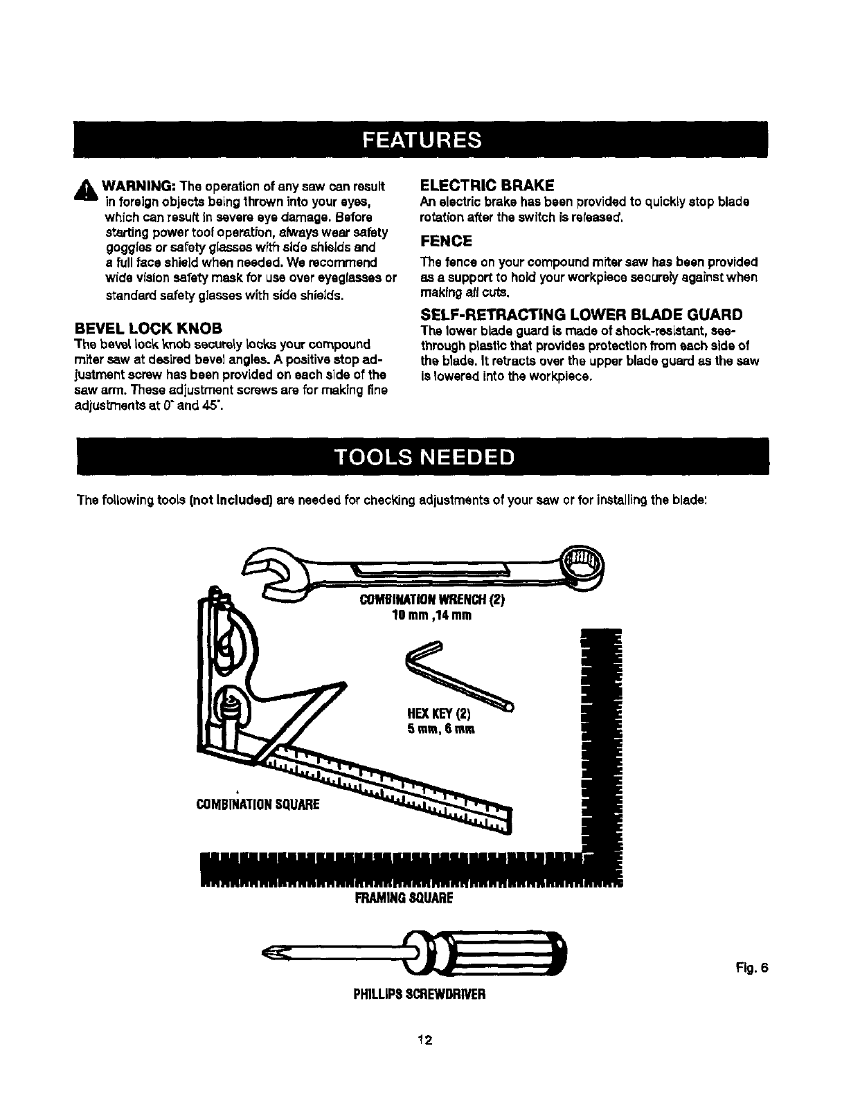
The followingtools (not Included) are needed for checkingadjustmentsof your saw or for ir_talling the blade:
COMBINATIONWRENCH(2)
10 mm,14mm
COMBINATIONSQUARE
FRAMINGSQUARE
PHILLIPSSCREWDRIVER
Fig. 6
12
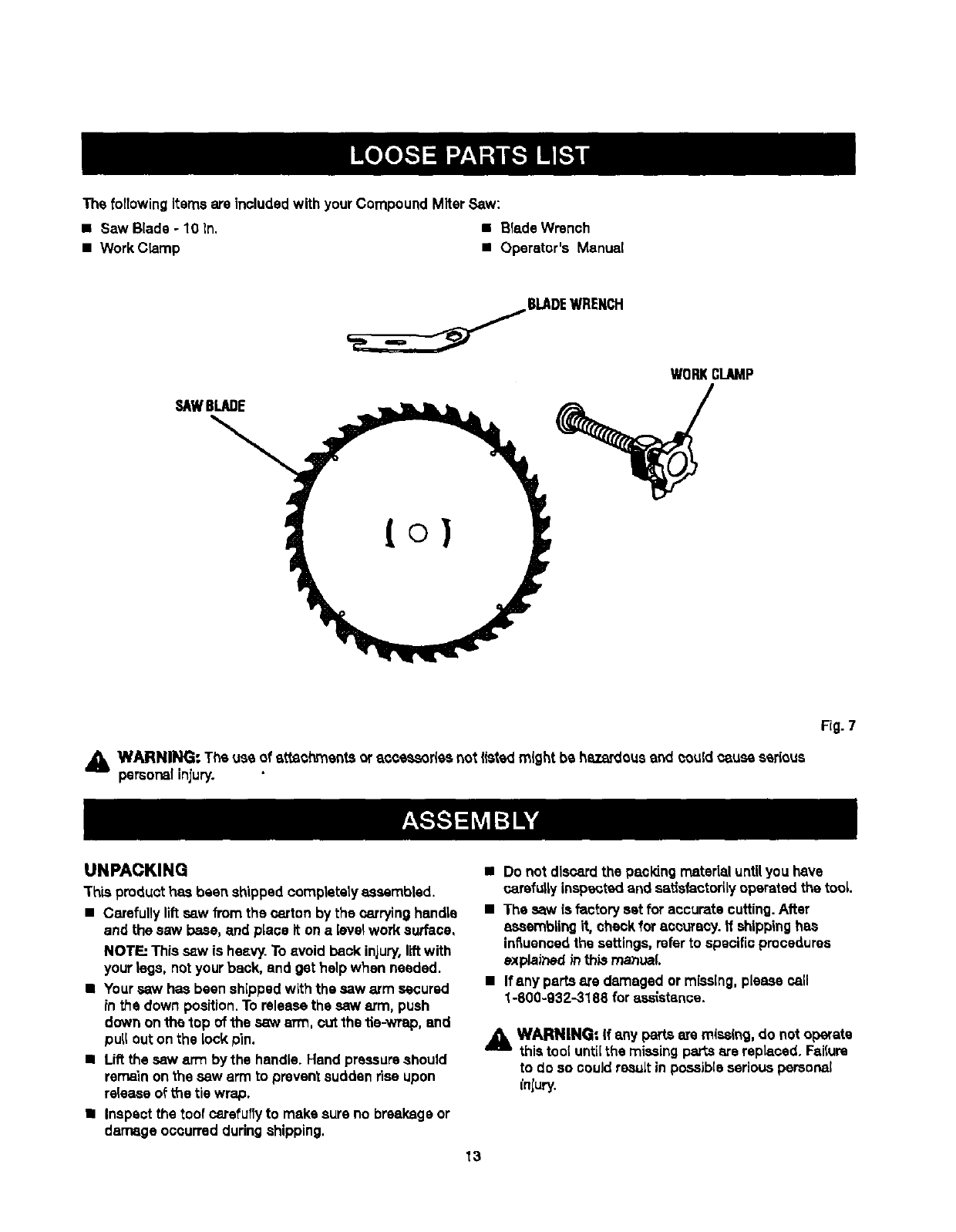
ThefollowingitemsareincludedwithyourCompoundMiterSaw:
•Saw Blade - 10 ln, •Blade Wrench
•Work C_amp •Operator's Manual
SAWBLADE
=,= _BLADEWRENCH
WnRKCLAMP
Fig. 7
,I_ WARNING: The use of atfachments oraccessoriesnot listed might be hazardousand couldcause ssdous
personalinjury.
UNPACKING
This product has been shipped completelyassambled.
•Carefully liftsaw from the carton by the carryinghandle
and the saw base, and place it on a level work surface,
NOT_" This saw is heavy.To avoid back iniury,liftwith
your legs, notyour back, and get help when needed.
•Yoursaw has beenshipped with the saw arm secured
in t_s down position.To release the saw arm, push
down on the top of the saw arm, cut the tie-wrap, and
pull outon the lock pin.
•Lift the saw arm by the handle. Hand pressureshould
remain onthe saw arm to prevent suddenrise upon
rslsasa of L_etie wrap.
•Inspect the tool carefuffyto make sure no breakage or
damage occurred duringshipping.
•Do not discardthe packing material untilyou have
carefullyinspectedand satlsfactodiyoperated tha tool
•The _w is factory set for accurate cutting.After
assemblingit, checkfor accuracy, ff shippinghas
inSusncedthe settings,referto spsciflcprocedures
explained inthis manual
•Ifanypartsaredamaged or missing, please call
1-800-932-3188 for assistance.
J_l WARNING= If any partsare missing,do not operate
this tootuntilthe missing partsare replaced. Failure
to do so couldresult in possibleseriouspersonal
inlury.
13
d_lb WARNII_I" Do not attempt to modify this tool or
createaccessories not recommended for usewith
this tool. Anysuch aitaratlon or modifl_,tion is
misuse and could result ina hazardouscondition
leading to possibleseriouspersonalinjury.
_k WARNINGs Do not connect to power supply until
assemblyis complete. Failureto comply could
result in accidental startingand possible serious
personal injury.
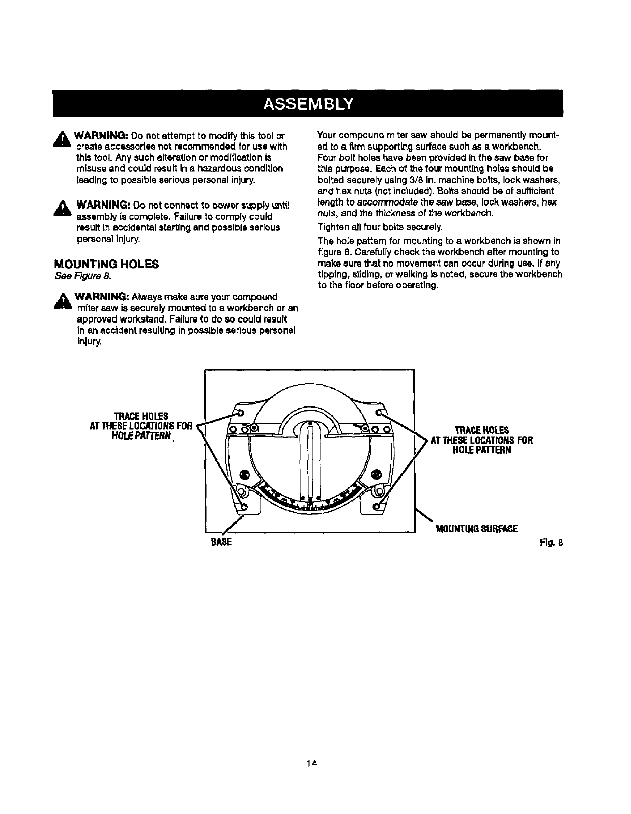
MOUNTING HOLES
See Figure 8.
WARNING: Ahe_ysmake sum your compound
mitersaw fs securelymountedto a workbench or an
approved wcrkstand. Failureto do so could result
in an accident resultingin poSSibleseriouspersonal
injury.
Your compoundmitersaw should be permanentlymount-
ed to a firmsupportingsurfacesuch as a workbench.
Fourbolt holeshave been providedin the saw base for
this purpose. Each of the four mountingholesshould be
boltedsecurely using3/8 in. machine bolts,lockwashers,
and he)( nuts(notinctuded). Bolts shouldbe of sufficient
length to acconvnodate the saw base, lockwashers, hex
nuts, and the thickness of the workbench.
Tightenall four bolts securely.
The hoJepe_ern for mountingto aworkbenchis shown in
figure 8. Carefullycheck the workbench after mountingto
make surethat no movementcan occur duringuse. If any
tipping, eliding,orwalking is notad, securethe workbench
to the floor before operating.
TRACEHOLES
ATTHESELOCATIONSFOR
HOLEPATTERN TRACEHOLES
ATTHESELOCATIONSFOR
HOLEPATTERN
BASE
NmUNTINGSURFACE
Fig. 8
14
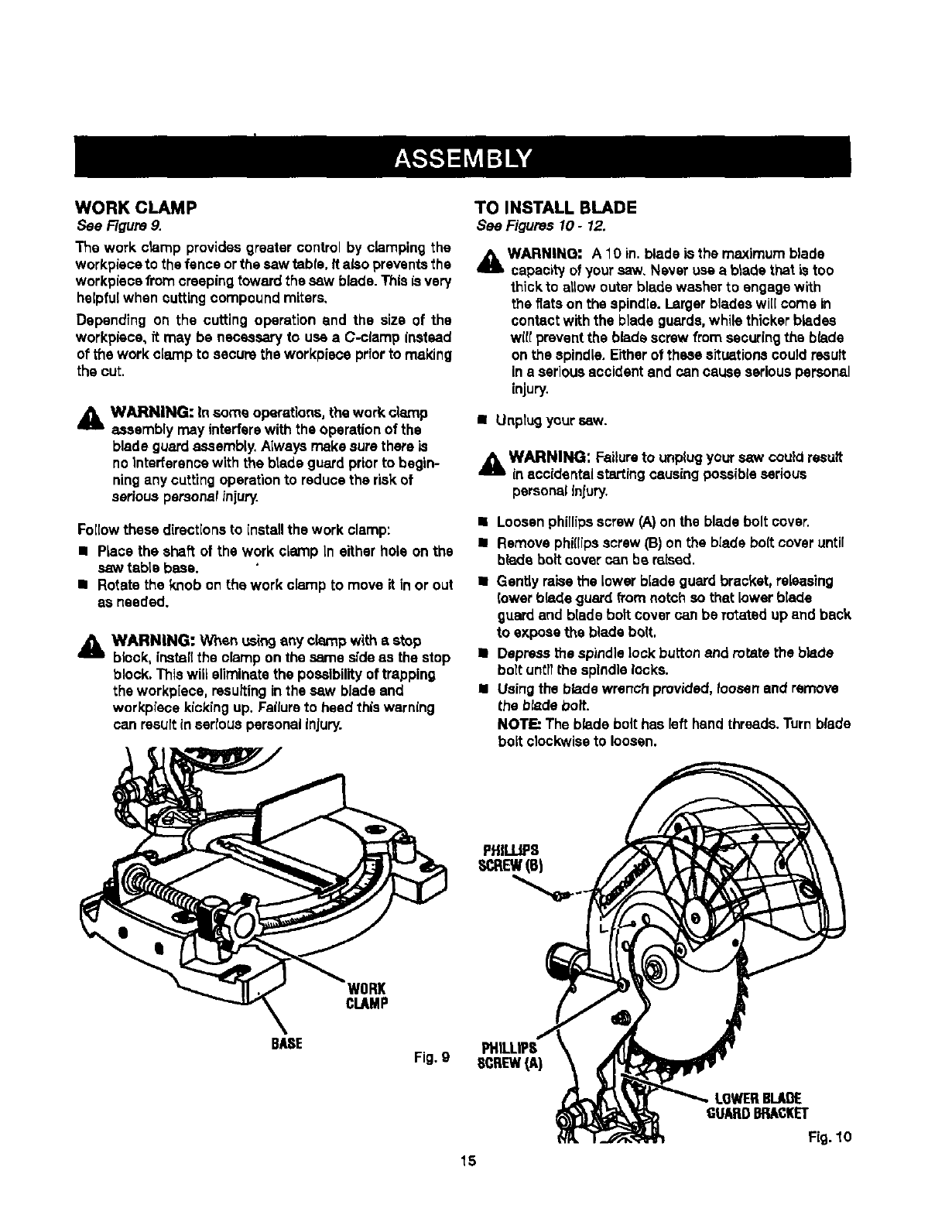
WORK CLAMP
See Figure 9.
The work clamp provides greater control by clamping the
workpisceto the fence orthe saw table. It also preventsthe
workpisosfrom creepingtoward the saw blade. This Lsvary
helpfulwhen cuttingcompoundmiters,
Depending on the cutting operatlon and the size of the
workplace, it may be necessaryto use aC-clamp instead
of the work clamp to secure the workpisca priorto making
the cut.
_k WARNING: In some operations,the work clamp
assemblymay interferewith the operationof the
blade guardassembly.Always make surethata is
nointerferanoewith the blade guard priorto begin-
ningany cuttingoperationto reducethe riskof
sedous personal injury.
Followthese directionsto installthe work clamp:
•Place the shaft of the work clamp in either hole on the
saw table bess.
• Rotate the knob on the work clamp to move it in or out
as needed.
AWARNING: When usingany clamp with astop
block, install the clamp on the same sideas the stop
block,This will eliminatethe possibilityof trapping
the workpiece, resultinginthe saw blade and
workplace kickingup. Failureto heed this warning
can resultin esrtous personalInjury.
TO INSTALL BLADE
See Figures 10- 12.
_L WARNING: A 10 in. blade is the maximum blade
capaoi_ of your saw, Never use a blade that is too
thickto allow outerblade washer to engage with
the fiats on the spindle. Largerbladeswi([come in
contactwith the blade guards,while thicker blades
wilt preventthe blade screw from securing the blade
on the spindle,Eitherof these situationscould result
ina seriousaccident and can cause seriouspersonal
injury.
•Unplugyour saw.
_k WARNING: Failureto unplugyour saw could result
inaccidentalstartingcausingpossibleserious
personalInlury.
•Loosenphillipsscrew (A)on the blade bolt cover.
•Remove phillipsscrew (B) on the blade bolt coveruntil
blade bolt cover can be raised.
• Gently raisethe lower blade guardbracket, releasing
lower blade guard fi'omnotch so that lower blade
guard and blade bolt cover can be rotated up and back
to exposethe blade bolt.
• Depress the spindle lock buttonand rotate the blade
bolt untilthe spindle locks.
II Using the blade wrench provided,loosen and remove
the blade bolt.
NOTE: The blade bolt has left hand threads.Turnblade
bolt clockwiseto loosen.
WORK
CLAMP
BASE
Fig.9 SCREW(,A)
LOWERBLADE
GUARDBRACKET
Fig. 10
15
BLAOE
\
BI.AOE
BOLTCOVER
PHILLIPS
SCREW
LOWER
BLADEGUARD
TO
LOOSEN FLAT(S)
TIGHTEN
BLADE
BOLT
OUTERBLADEWASHER
W_H DOUBLE"D'FLATS
INNERBLADE
WASHERWITH
DOUBLE"17'FLATS
Fig. 11
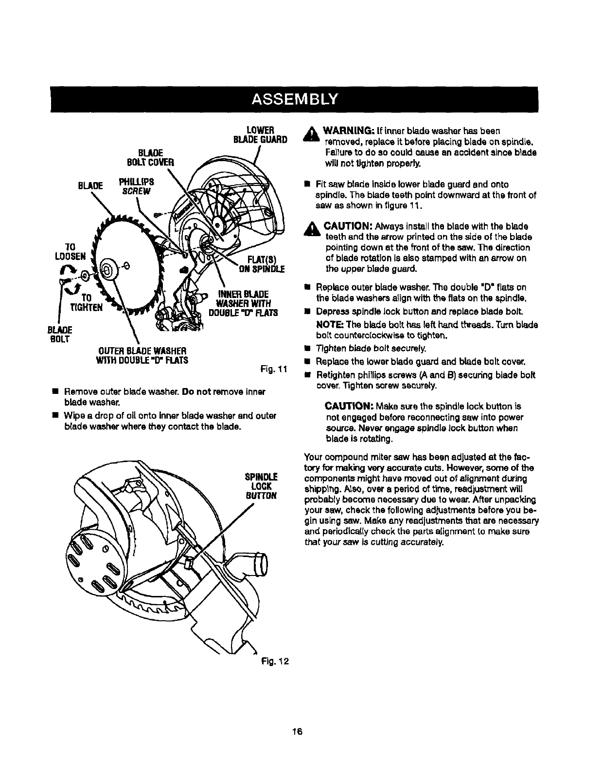
•Remove outer blade washer. Do not remove inner
blade washer.
•Wipe a drop of oil onto Innerblade washerand outer
blade washerwhere they contact the blade.
SPINDLE
LQGK
BUTTON
WARNING: If inner blade washer has been
removed,replace it before placingblade onspindle.
F_lure to do so could cause an accident since blade
will not tightenproperly.
• Fit saw blade insidelower blade guardand onto
spindle.The bladeteeth point downward at the front of
saw as shown infigure11.
A CAUTION: Alwaysinstallthe blade with the blade
teeth and the arrow printed on the sideof the blade
pointing down at the front of the saw. The direction
of blade rotation Is also stamped with an arrow on
the upper blade guard,
•Replace outer blade washer.The double "D"flats on
the blade washersalign with the fiats on the spindle,
I Depressspindle lock buttonand replace blade bolt.
NOTE: The blade bolt has left hand threads.Turnblade
bo{tcountsrc(ockwiseto tighten.
•Tightenblade bolt securely.
• Replace the lower blade guard and blade bolt cover.
II Retightsn phillipsscrews (A and B) secudngblade bolt
cover.Tighten straw securely.
CAUTION: Make sure the spindle lock buttonis
not engaged before reconnectingsaw into power
source. Never engagespindle Jookbutton when
blade is rotating.
Your compoundmitersaw has been adjustedat the fac-
tory for making very accurate cuts. However,some of the
componentsmight have moved out of alignment during
shipplng.Also, overaperiod of time, read]ustmenLwill
probabtybecome necessarydue to wear. After unpacking
your saw, check the followingadiustmentebefore you be-
gin usingsaw. Make any readjustmentsthat are necessary
and periudica((ycheck the partsa(ignmentto make sure
that your saw is cuttingaccurateJy.
Fig. 12
16
NOTE:Manyoftheillustrationsinthismanualshowonly
portionsofyourcompoundmitersew,Thisisintentions]
sothatwecanciearlyshowpointsbeingmadeintheIl-
lustrations. Never operate your Rawwithout all guard==
securaJy in place end in good operating condition.
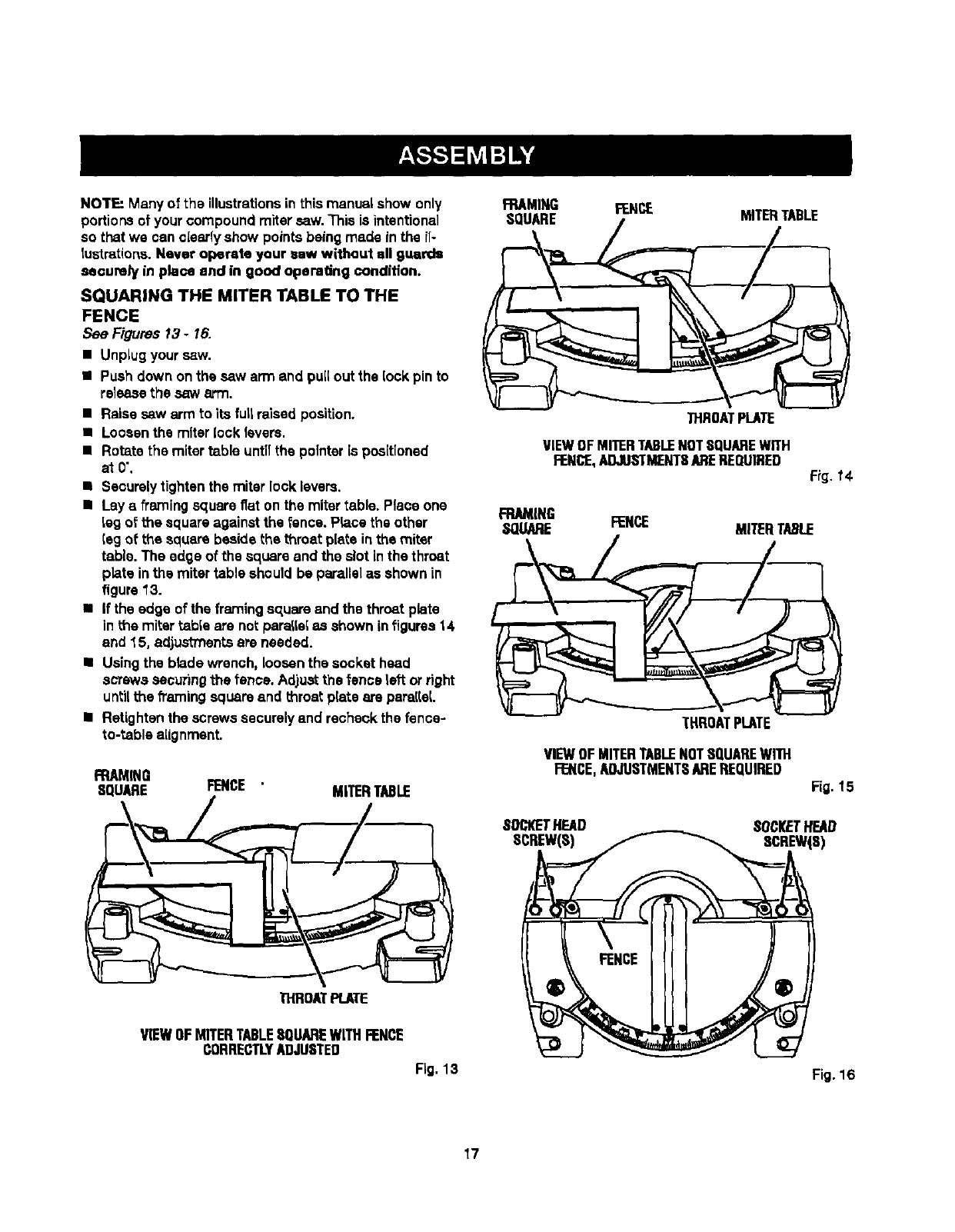
SQUARING THE MITER TABLE TO THE
FENCE
See Figures 13- 16.
• Unplugyour saw.
• Push down on the sew arm and pu[I outthe lock pin to
releasethe saw arm.
•Raise saw arm to its fultraised position.
•Loosenthe miter lock levers.
•Rotate the miter table untTIthe pointer is positioned
atO'.
•Securelytightenthe miter lock levers.
•Lay aframing square fiat on the mitertable. Place one
tag of the square against the fence.Pla.cethe other
(eg of the square beside the throat plate inthe miter
table. The edge of the square and the slot inthe throat
plats inthe mitertable shouldbe parallelas shown in
figure13.
•If the edge of the framingsquare and the throat plate
in the mitertabfe are not paraliefas shown infigures14
and 15, adjustmentsare needed.
•Using the blade wrench, loosenthe socket head
screws securingthe fence. Adjustthe fence left orright
untilthe h'amlngsquare and throat plate are paraReL
•Retighten the screws securelyand recheckthe fence-
to-table alignment,
FRAMING
SQUARE FENCE MITERTABLE
FRAMING FENCE
SQUARE /MITERTABLE
THROATPLATE
VIEWOFMITERTABLENOTSQUAREWITH
FENCE,ADJUSTMENTSAREREQUIRED F_g.f 4-
FRAMING
SOUARE FENCE
THROATPLATE
VIEWOFMITERTABLENOTSQUAREWITH
FENCE,ADJUSTMENTSAREREQUIRED Fig. 15
SOCKETHEAD SOCKFTHEAD
SCREW(S) SCREW(S)
THROATPLATE
VIEWOFMITERTABLESQUAREWITHFENCE
CORRECTLYADJUSTED
Fig. 13 Fig. 16
17
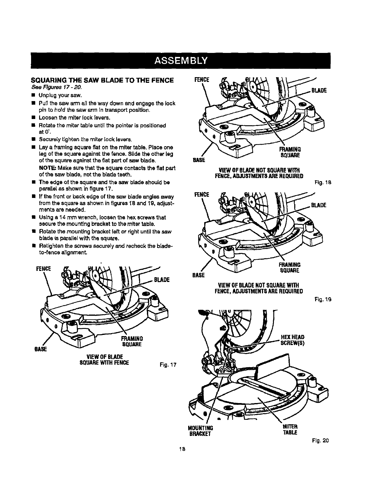
SQUARINGTHE SAWBLADETOTHE FENCE
See Figures 17 -20.
• Unplug your saw.
•Pu[[ the saw arm a[I the way down and engage the lock
p_nto hold the saw arm in transport position.
•Loosenthe miterlock Ievere.
•Ro_ztethe miter table unti[the pointer is positioned
at0".
•Securely tighten _le miter [ooklevers.
•Lay a framing square fiat on the mitertable. Place one
leg of the square against the fence. Slide the other leg
of the square against the fiat paTtof saw blade.
NOTE: Make surethat the square contactsthe fiat pert
of the saw blade, notthe blade teeth.
•The edge of the squareand the saw blade should be
parallelas shown infigure 17.
•If the front or back edge of the saw blade angles away
fromthe square as shown infigures18 and 19, adjust-
merits are needed.
•Usinga 14 mm wrench, loosenthe hex screws that
securethe mountingbracketto the mitertable.
•Rotate the mountingbracket lei_tor rightuntilthe saw
blade Lspara.[[e(w}th the squaze,
•RatJghtenthe screwssacure[y and recheckthe b[ade-
to-fence alignment.
FENCE
FENCE
BASE
FENCE
BASE
FRAMING
SQUARE
VIEWOFBLADENOTSQUAREWITH
FENP..,E,ADJUSTMENTSAPEREQUIRED
FRAMING
SQUARE
VIEWOFBLADENOTSQUAREWITH
FENCE,ADJUSTMENTSAREREQUIRED
Fig. 18
BLADE
F_.lg
BASE
FRAMING
SQUARE
VIEWOFBLADE
SQUAREWITHFENCE Fig. 17
HEXHEAD
MOUNTING
BRACKET
MI'I'ER
TABLE
Fig. 20
18
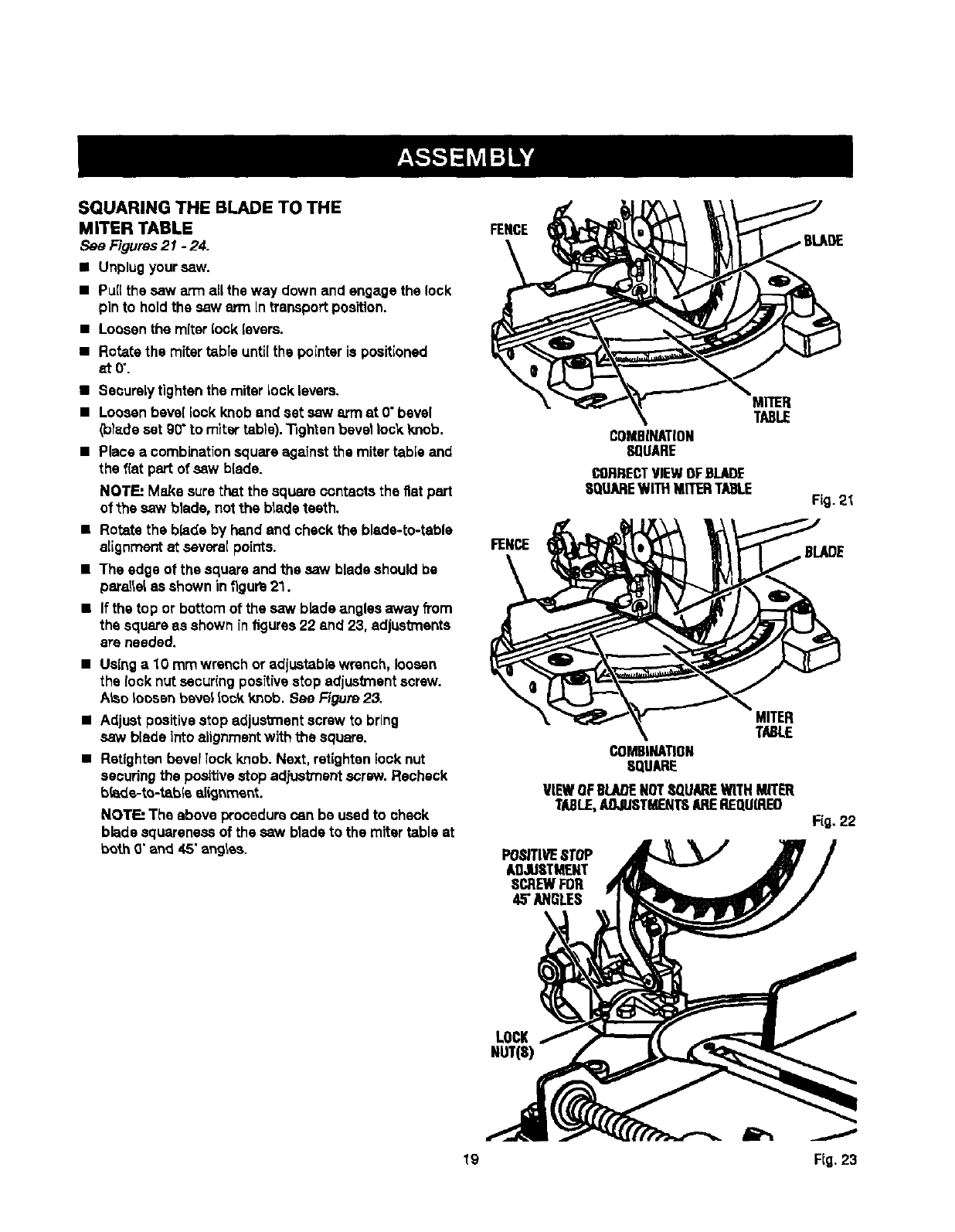
SQUARINGTHE BLADETO THE
MITERTABLE
See Figures21 -24.
•Unplugyoursaw.
•Puffthe saw arm allthe way down and engage the lock
pin to hold the saw arm In transportposition.
•Loosenthe miterlock {avers.
•Rotatethe mitertable untUthe pointer is positioned
_t0".
•Securelytightenthe miter Locklevers.
•Loosenbevel lock knob and set saw arm at 0"bevel
(io)adeset g0"to miter table)."nghtenbevel lock knob.
•Place a combinationsquare against the miter table and
the fiat part of saw b{ade.
NOTE: Make surethat the square contactsthe fiat part
of the saw blade, not the blade teeth.
•Rotate the blade by hsnd and check the blade-to-table
alignment at severe{points.
•The edge of the square and the saw bladeshould be
paraIle&as shown in figure21.
•If the top or bottom of the saw blade angles away from
the square es shown in figures22 and 23, adjustments
ere needed.
•Using a10 mm wrench or adjustable wrench, loosen
the lock nut sscur(ng positivestop adjustmentscrew.
ALsoloosen beve_lock 'Knob.See F_gum23.
•Adjust positive stop adjustment screw to bring
saw blade Into alignmentwith the square.
•Retighten bevellock knob.Next, retightenlock nut
securingthe positivestopad,h._tmsntscrew. Recheck
bk_de-to-tsb{e alignment.
NOTE: The above procedurecan be used to check
blade squareness of the saw blade to the miter table at
both 0"and 45"angles.
FENCE
FENCE
MITER
TABLE
COMBINATION
SQUARE
CORRECTVIEWOFBLADE
SQUAREWITHMITERTABLE
MITER
TABLE
COMBINATION
SQUARE
VIEWOFBLADENOTSQUAREWITHMITER
TABLE,AOJIJSTMENTSAREREQU(REO
POSITIVE8TOP
ADJUSTMENT
SCREWFOR
45"ANGLES
LOCK
FiO.
BLADE
F(g. 22
J
19 FIG.23
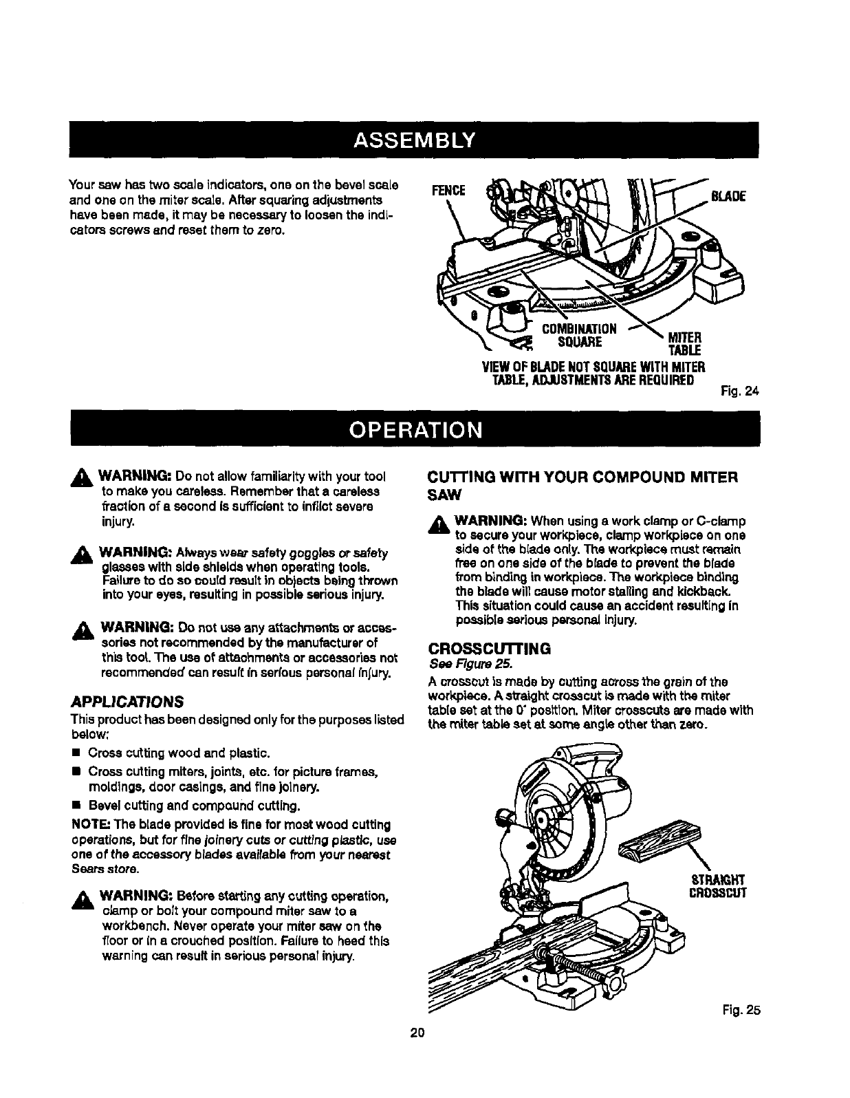
Yoursawhastwoscaleindicators,oneonthebevelscale
andoneonthemiterscale.Aftersquaringadjustments
havebeenmade,itmay be necessaryto loosenthe indi-
cators screws end reset them to zero.
FENCE BLADE
COMBINATION
SQUARE MITER
TABLE
VIEWOFBLADENOTSQUAREWiTHMITER
TABLE,ADJUSTMENTSAREREQUIRED Fig. 24
_1, WARNING" Do not allow familiarity with yourtool
to make you careless.Remember that a careless
fraction of a second is sufficientto inflictsevere
injury.
_, WARNING: Alwayswear safety goggles orsafety
glasseswith side shieldswhen oparat]ngtools.
Failureto do so could resultin objects beingthrown
into your eyes, resultingin possibleserious injury.
A WARNING: Do not use _ny attachments or acces-
sories not recommended by the manufacturer of
this tool The use of attachments or scceseorise not
recommended can result inserfous persona| fnJ'ury.
APPLICATIONS
Thisproduct has beendesignedonlyfor the purposeslisted
below:
• Cross cuttingwood and plastic.
•Cross cuttingmiters, joints, etc. for pictureframes,
moldings, door casings,and finejotnery.
•Bevel cuttingand compQundcutting.
NOTE=The blade providedis fine for mostwood cutting
operations,but for finejofnerycuts or cuttingpisstlc, use
one of the accessory blades availablefrom your nearest
Sears store.
_, WARNING: Before stetting any cuttingoperation,
_brnp or bolt your compound miter saw to a
workbench. Never operate your miter saw on the
floor or in s crouched position.Failureto heed this
warning can resultin seriouspersonalinjury.
CU'I-rlNG WITH YOUR COMPOUND MITER
SAW
_k WARNING: When usinga work clampor C-clamp
to secureyourworkpisce, clampworkpisce on one
side of the blade o_y. The workpiscemust remain
_'ee on one sideof the bradsto prevent the blade
from bindinginworkpisoe.The workpiecebinding
the blade will cause motor stallingand kickback.
This situationcould cause an accident resultingin
possibleseriouspersonalinjury.
CROSSCU'n'ING
See Figure 25.
A crosscutis made by cuing across 1hegrain of the
workplace. A sVa",ghtcrosscutis made with the miter
table set at the 0" position.Miter crosscutsere made with
the mitertable set _t some angte other than zero.
_TRAIGHT
CRD38CLIT
2O
Fig.25
TO MRrERCUT
• Pullout the lock pin and liftsaw arm to its full height.
•Loosenthe miter lock levers.
•Rotate the saw table until the pointer alignswith the
desired angle onthe miter scale.
•Tighten the miter lockleverssecurely.
_k WARNING: Toavoid seriouspersonalinjury, always
tighten the miter lock handlesecurely before making
a cut. Failureto do so could result inmovement of
the controlarm or mitertable while makinga cut.
•placethe workpiece flat onthe mitertable withoneedge
securely againstthe fence. If the board is warped, placa
the convex side against the fence. If the concave edge
of aboard is pisced against the fence, the board could
collapse on the blade at the end of the cut, jammingthe
blade.
•When cuttinglongpieces of lumberormolding, support
the opposite end of the stock with arelierstand or with
a work surface isve( with the saw tabte. See Figure 30.
•Aligncuttingline on the werkplece with the edge ot saw
blade.
•Grasp the stock firmly with one hand and secure
it against the fence or use the optionalwork clamp or a
C-clamp to securethe wcrkplece.
_L WARNING: To avoid seriouspersonal injury,keep
your hands outside the no hands zone; at least 3
in. from blade. Never performany cuttingoperation
freehand (withoutholdingworkpisoa against the
fanoa). The blade could grab the workpieoaif it slips
or twists.
•Beforeturningonthe saw, performadryrunofthe cutting
operationjust to make sursthat no problemswilt occur
when the cut is made.
•Grasp the saw handle firmlythen squeeze the switch
kiggsr. Allow several seconds for the blade to reach
maXimumspeed.
•Slowly lower the blade into and throughthe workpieoa.
•Releasethe switchtriggerandallow the saw bledetostop
rotating before raisingthe blade out of workpisca. Wait
untilthe eiscb'icbrake stops blade from turning before
removingthe workplece fromthe miter table.
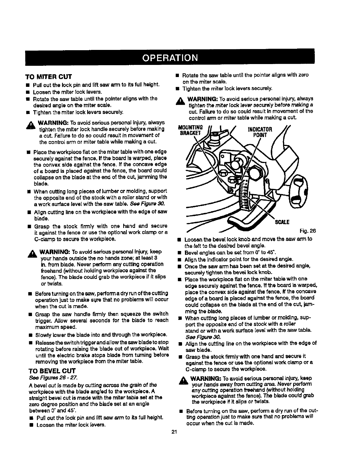
TO BEVEL CUT
see Figures26 -27.
A bevel cut Is made by cutting across the grainof the
werkpisce with the bradeangled to the workpleoa. A
straightbevel cut is made with the miter table set at the
zero degree positionand the blade sot at an angle
between 0"and 45".
•Pull out the (ock pin and riftsaw arm to its full height.
•Loosenthe miterlock levere.
•Rotate the saw table untilthe pointeralignswith zero
on the miterscale.
•Tighten the miterlock leverssecurely.
_lb WARNING: Toavoid seriouspersonalinjury,always
tighten the miter lock leversecurelybefore makinge
cut. Failureto do so could resultin movement of the
controlarm or miter tabte while makinga cut.
MOUNTING INDICATOR
BRACKET POINT
Fig. 26
•Loo_¢ the bevel lockknob end move the saw arm to
the left to the desiredbevel angle.
•Bevelengles can be sat from 0"to 45".
• Align the indioator pointfor the desiredangis.
•Once the saw arm has been setat the das_'edangle,
seou_ly tighten the beve_lock knob.
•pisce the workpiace flat onthe miter table with one
edge escurotyagainst the fence, it the boardis warped,
place the convexside againstthe fence. If the concave
edge of a board is placed againstthe fence, the board
could collapseon the blade at ths end of the cut, jam-
ming the blade.
•When cutting longpieces of lumberor molding, sup-
port the opposite end of the stock with a roller
stand orwith a work surface[eve]with thesaw table.
See F-Tgure30.
•Alignthe cutting lineon the workpiecawith the edge of
saw b_de.
•Grasp the stock firmlywith one hand and secureit
against the fence or use the optionalwork clampor a
C-oiamp to secure the workpleoa.
_1_ WARNING: To avoid seriouspersonalinjury,keep
your hands away from Guttingarea. Never perform
,,ny cuffing operationfreehand(withoutholding
workpisceagainst the fence}. The btade couldgrab
the workpisoa if it slips or twists.
•Beforeturningon the saw, perform a dryrun of the cut-
ting operationjust to make surethat no problemswill
occur when the cut Is made.
21
•Grasp the saw handle firmlythen squeeze the switch
trigger.Aflowseveral secondsfor the blade to reach
maximum speed.
•S1owlylower the blade into and throughthe workplece.
•Release the switch triggerand allow the saw blade to
stop rotating beforeraisihgthe blade out of workplace.
Wait untilthe electric brake stopsblade from turning
before remo,_in_the wark_iece fro_'nmitertable.
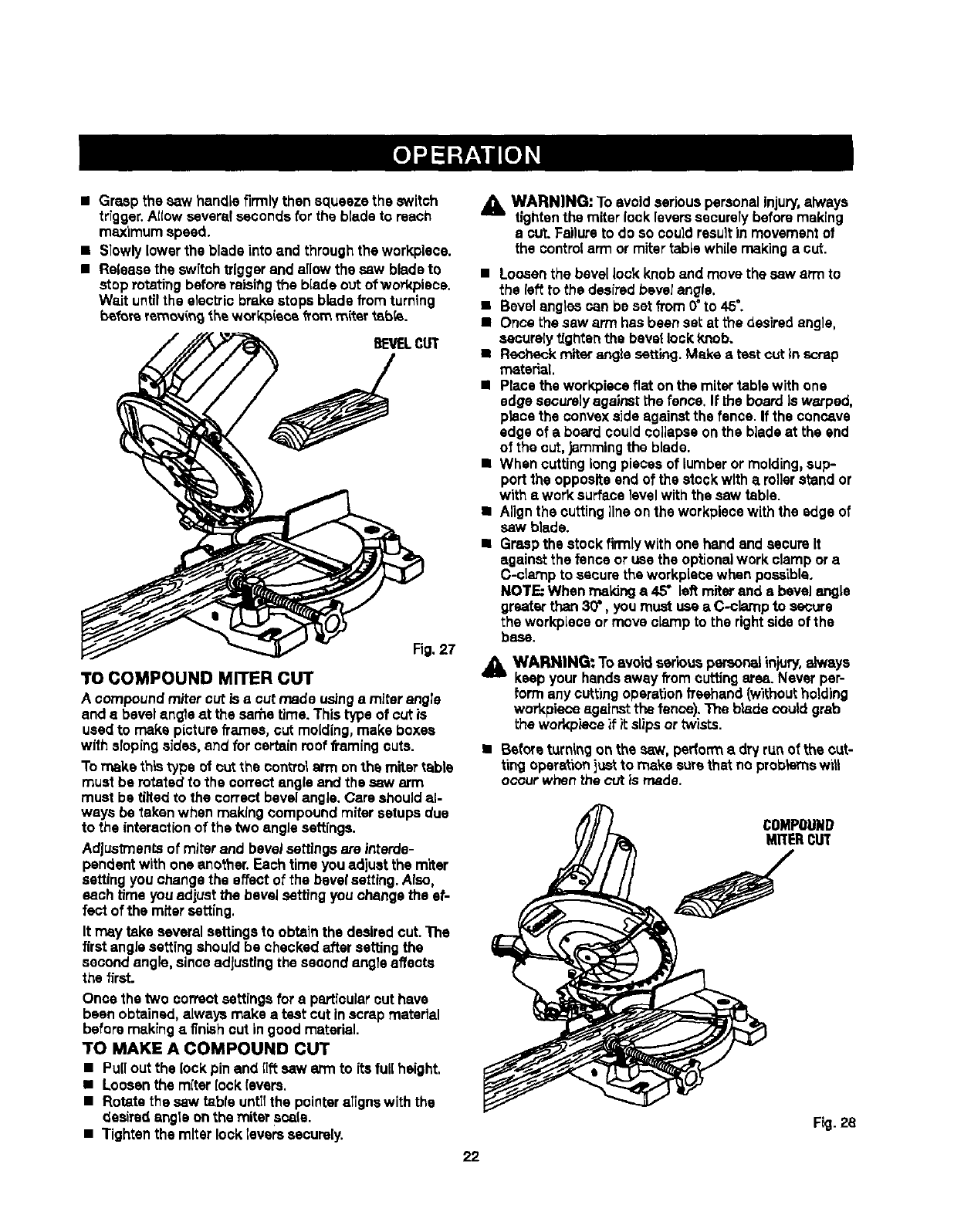
BEVELCUT
Fig.27
TO COMPOUND MITER CUT
Acompound miter cut is e cut made usingamiterangle
and abevel angle at the sarhetime. This type of cut is
usedto make pictureframes, cut molding,make boxes
with slopingsides, end for certain roof framingcuts.
To make this type of cut the conVolarm on the miter table
must be rotated to the correct angle and the saw arm
must be tilted to the correct bevelangle. Care shouldal-
ways be taken when making compound mitersetups due
to the interactionof the two angle settings.
Adjustments of miterand beveJsettings are interde-
pendent with one another.Each time youadjust the miter
setting youchange the effectof the bevelsetting.Also,
each time youadjust the bevelsetting you change the ef-
fect of the miter setting.
It may take several settingsto obtainthe desiredcut. The
firstangle setting should be checked after setting the
second angle, sinceadjustingthe secondangle affects
the first.
Once the two correct settings fora particularout have
been obtained,always make a test cut in scrap material
beforemaklng a finish cut ingood material.
TO MAKE A COMPOUND CUT
•Puffout the lock pin and riftsaw arm to its full height.
•Loosenthe miter lock levers.
•Rotate the saw table untilthe pointeraligns with the
desired angle onthe miter scala.
•Tighten the miter locklevers securely.
WARNING: To avoid seriouspersonal injury,always
tightenthe miter lock levers securelybefore making
acut. Failureto do so couldresult in movementof
the controlarm or mitertable while making a cut.
•Loosenthe bevel lockknob and move the saw arm to
the {eft to the desiredbevelangle.
•Bevelangtescan be set from0°to 45°.
• Once the saw arm has been set at the desiredangle.
securelyt{ghtenthe bevel lock knob.
• Recheck mher angle setting. M_e atest out inscrap
mstedaL
•Place the workpieceflat on the mitertable with one
edge securelyagainst the fence. If the board is warped,
placethe convexside against the fence. If the concave
edge of a board couldcollapse onthe blade at the end
of the cut, jammingthe blade.
•When cutting longpieces of lumberor molding,sup-
port the opposite end of the stock with a rollerstand or
with awork surface]evelwith the saw table.
•Alignthe cuttingline onthe workplecewith the edge of
saw blade.
•Graspthe stock firmly with one hand and secureIt
against the fence or use the optionalwork clamp or a
C-clamp to securethe workplacewhen possible.
NOTE When maLdnga 45" left miter and a bevelangts
greater than30", you must use aC-cismp to secure
the workpieceor move clamp to the rightsideof the
base.
_1= WARNING: To avoid seriouspersor_ injury, always
keep your handsaway from cutting area. Never per-
form any cutting operationfreehand (wiLhoutholding
workpieceagainstthe fence).The blade couldgrab
the wed<pieceif it slipsor twists.
•Beforeturningon the saw. perform a dryrun of the cut-
ting opera,|oni_ to make sure tha_noprobk_nswilt
occur when the cut is made.
Fig.28
22
• Grasp the saw handle firmlythen squeezethe switch
trigger.Allow severalseconds for the blade to reach
m_x_mum speed.
• Slowly lowerthe blade into and throughthe work-
p(ece. See/:{gum 28.
•Releasethe switch trigger and allow the saw bladeto
slop rotatingbefore raisingthe blade out ofworkpiece.
Wait untilthe electric brake stops blade from turning
before removingthe workpiece from mitertable.
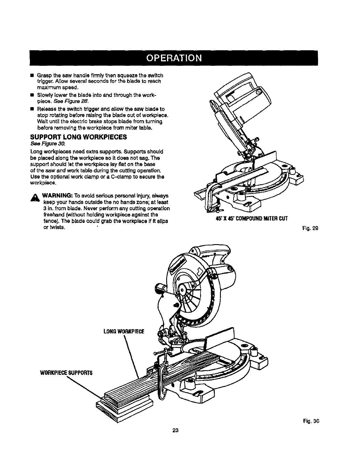
SUPPORT LONG WORKPIECES
See Figure 30.
Long workpiecasneed extra supports.Supportsshould
be placed alongthe work,piece so it does not sag. The
support should let the workplace lay fiat on the base
ot the saw and work table duringthe cutting operation.
Use the optionalwork c[,_Tlpor aC-clamp to secure the
workplace.
AWARNING: To avoid seriouspsreona_injury, always
keep your hands outsidethe no hands zone; at least
3 in, from blade. Never performany cuttingoperatfon
freehand (withoutholdingworkpieceagainst the
fencel. The bhde coutd grab the workplace if It sl(ps
or twists.
45"X 45"COMPOUNDMITERCUT
Fig.29
LONGWORKPIECE
WORKPIECE_LIPPOITI_
23
Fig. 30

CUTTING COMPOUND MITERS
"toa_din makingthe correct settings,the compound angle se_ing chart botowhas been provided.Since compoundcuts
are the most difficultto accurately obtain,trial cuts should be trade inscrap material,and muchthoughtand plannfng
made, priorto making your requiredcut.
prrcH NUMB-:R OF $1DE,_
ol:=o,= 4 I 5 6 I7I8I9 I 10
0o M-45.00 °M-36.00 °M-30,00 =M-25.71 =, M-22.50 =M-20.00 °M- 18.00 °:
B- 0,00 ° B- 0,00 = B- 0.00 = B- 0.00 ° B- 0.00 °B- 0.00 °B- 0.00 =
5=M-44.89 =M.35.90 °M-29,91 =M-25.63 =M-;?.2.4.2== M-19.93 °M-17.94 =
B" 3,53 =B- 2.94 -= B,- 2.50 =B- 2.17 =B- 1.91 °B- 1.71 =B- 1.54 °
10°M-44.56 °M-35.58 =M-29.62 °M-25.37 °M-22.19 =M-19.72 =M-17.74 °
B- 7.05 °B- 5.86 °B- 4.98 ° B- 4.32 ° B- 8,81 =B- 3.40 °]_- 3.08 °
_-44,01 = M-35.06 °M-29.15 =M-24,85 =M-21.81 °M-19.37 =M-17.42 °
1'5°B-10.55 QB- 8.75 ° B- 7,44 °B- 6,45 =B- 5.68 °B- 5.08 °IB- 4.59"
M-43.22 °M-34,32 ° ;M-28.48 °M-24.35 =M-21.27 =M-18.88 =M-16.98 =
20= B-'_4.00 ° _-_1.60 ° B- 9,85 °B- 8.53 ° B- 7.52" B- 6.72 °B,- 6.07 =
25° M-42.19 =M-33.36 °M-27.62 ° M-23.56 ° M-20.58 °M-18.26 °M-16.41 °
B-17.39 °B-14,38 °B-12.20 °B-10.57 °B- 9.31 ° B- 8.31 ° B- 7.50 =
300 M-40.89 °M-32.18 =M-26.57=: M-22.84 °M-19.73 °M-17.50 °M-15.72 =
B-20.70 °B-17.09 °B-14.48 °B-12,53 ° B-11,03 °B- 9.85 ° B- 8,89 °
35 °M-39.32 =M-30.76 =M-25.31 =M-21.53 °M-18.74 ° M-16.60 ° M-14.90 °
B-23,93 °B- 19.70 = B- 16.67 °B- 14.41 °B- 12,68 °B- 11.31 _B- 10.21 =
40" M'37'45= M-2g'_0° M'23'86° M'20"25= 1_'17"6G° M'15"56° M'13'98=
B- 27.03" B- 22.20 qB- 18.75 °B- 16.19 = B- 14.24 °B- 12.70 q B- 11.46 °
45" M-35.28 ° M-27.19 °M-22.21 °M-18.80 =M-16.32 °M-14.43" M-12,94'
B- 3O.O0° B-24,56 ° B-29.70 =B-17,57 ° B-15.70 =6-14.00 °6-12,62 °
M-32.73 °M-25.03 =M-20.36 °M-17.20 °M-14,91 °IM-13.17 °M-11.80 =
50° B-32.80 ° B-26.76 ° B-22.52 °B-19.41 °B-17.05 °B-15.19° B-13.69 =
55 =M-28.84 °M-22.62 =M-'t8.32 °M-15.44 o M-13,36 =M-11.79 °M-10.56 o
B-35.40 °B-28.78 °B-24,18 =B- 20.82 `> B-18.27 °B-18.27 ° B-14.66 °
60 ° M-26.57 °M-19.96 °M-18.10 °M-13,54 °M-11.70 =M-10.31 °M- 9.23 =
B-3736 °B-30.60 ° B-25._6 °B-99.07 °B-_9.35 =B-17.23 ° B-16.52 °
M-22,91 = M-17,07 = M-13,71 =M-11.50 =M- 9.93 °M- 8.74" M- 7.82 °
65 °B- 39.86 °B- 32.19 °B- 25.95 _B- 23.16 °13-20.29" 13-18.06 °B -16.26 °
70 = M-18.88 = M-13.95 =M-11.17 °M- 9.35 =M- 8.06 =M- 7.10 =M- 6.34 °
B-41.64 °B- 33.53 =B-28.02 °B- 24.06 =B-21.08' B- 18.75 =B- 16.88 °
75°M-14.51 °M-10.65 ° M- 8.50 °M- 7.10 °M- 6.12 =M- 5.38 ° M- 4.81 °
B- 43.08 °B-34.59 =B-28.88 =B-24.78 =B- 21 .Cog=B- 19.29 =13- 17.37 =
80 °M- 8.85 °M" 7,19 =M- 5.73 =M" 4.78 =M- 4.11 °M" 3,62 =M" 3.23 °
B" 44.14 = B-35.37 ° B-29.50 ° B-25,30 °B" 22.14 ° 13"19.68 °B" 17.72 °
M- 4.98 °M- 3.62 =M- 2.88 °M- 2.40 ° M-2.07 °M-1,82 °M- 1.62 =
85 ° B. 44.78 o18-35.84o B-29.87 °B-25.61 °B-22.41 °B-19.92 °1_.17.93 °
90 ° IM- 0.0O° M- 0.00 ° M- 0.00 =M- 0,00 = M.- 0.00 _M- 0.00 °M- 0.00 =
6- 45.00 = B- 36.00 = B- 30.00 ° B- 25.71" B- 22.50 ° B- 20.00" B- 18.00 °
Each B (Bevel)and M (_iter) Setting is Givente the Closest 0.005°.
COMPOUND-ANGLE SETTINGS FOR POPULAR STRUCTURES
24
CUT'rING CROWN MOLDING
Your compoundmRersaw doesan excellent Jobof cutting
crown molding. In general, compoundmiter saws do a
better job of cutting crownmoldingthan any other tool
made.
In orderto fit properly,crown moldingmust be compound
mitered with extreme accuracy.
The two contact surfaceson apiece of crown molding
that fit flat against the ceilingand the wall of aroom are at
angles that, when added together, equal exactly go'. Most
crown moldinghas a top rear angle (the section that fits
fiat against the cs[Ting)of 52"and a bottom rearangle (the
section that fits fiat against the wall) of 38".
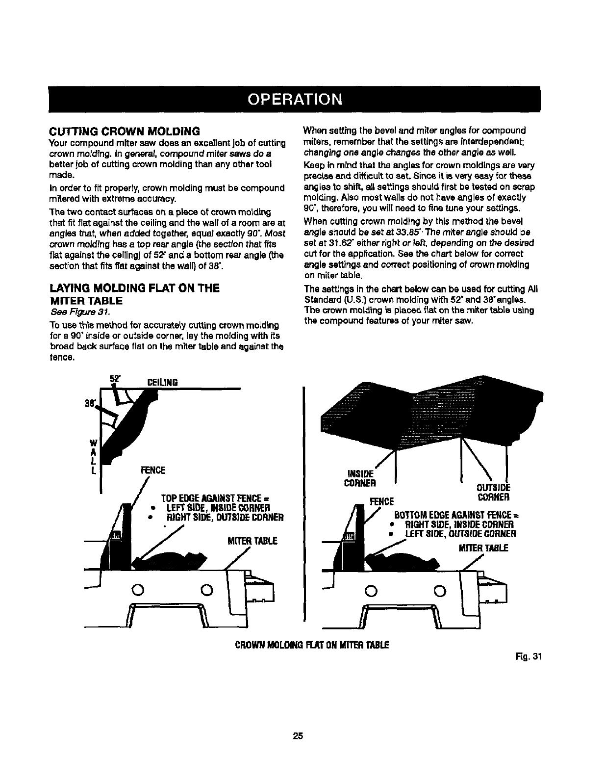
LAYING MOLDING FLAT ON THE
MITER TABLE
See Figure 31.
"1"ousethis method for accucateLycut_mg crownmolding
for a 90"insideor outside corner,lay the moldingwith its
broad back surfaceflat onthe miter table and against the
fence.
52" CEILING
When setting the beveland miter angles for compound
miters, rememberthat the settingsare interdependent;
changingone angle changes the other angle as well.
Keep in mind that the angles for crownmoldings are very
precLseand diffLcuitto sat. Since it tsvery easy for these
angles to shift, allsettings should firstbe tested on scrap
molding.Also most wells do not have angles of exactly
90",therefore, you witlneedto finetune yoursettings,
When cuttingcrown moldingby thismethod the bevel
angle should be set at 33.85".The miter angle shouldbe
set at 31.62"either dght or left, dependingon the desired
cut for the application.See the chart below for correct
angle settings and correct positioningof crownmolding
on miter _ble.
The settings in the chartbelow can be used for cuttingAll
Standard (U.S.) crownmoldingwith 52"and 38"angles.
The crown motdthgis plaoe(ifiat on the miter table us'rag
the compoundfeaturesof your mitersaw.
TOPEDGEAGAINSTFENCE=
* LEFTSIDE,IH$IDE¢6RNER
• RIGHTSIDE,OWSIDECONNER
MITERTABLE
0 0
INSIDE
CORNER
FEHCE
OUTSIDE
CORNER
BOTTOMEDGEAGAINSTFENCE=
•RIGHT81DE,iNSIDECORNER
•LEFTSLOE,OUTStOECORNER
MITERTABLE
0 0
CROWNMOLDINGFLATONMITERTABLE
F(g. 31
25
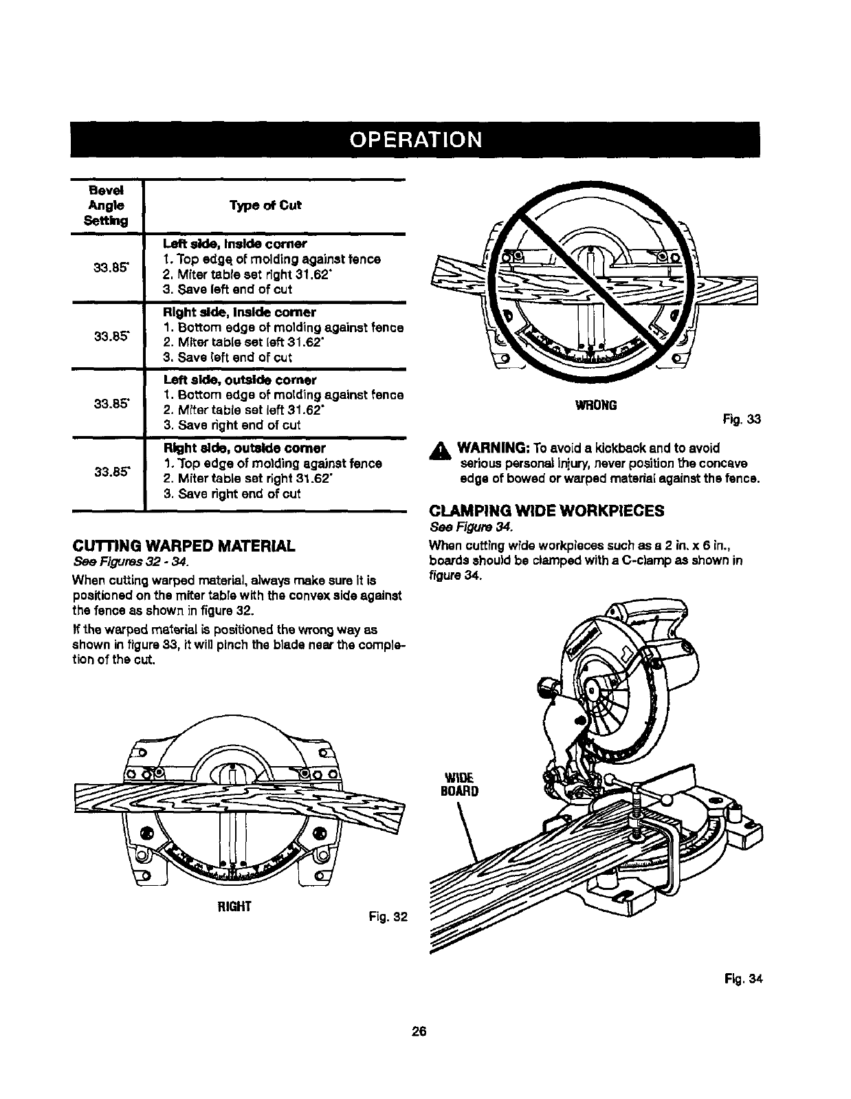
Bevel
Angle Typeo#Cut
Setth_g
side, inside comer
1. Top edge.of molding against fence
33.85" 2. Miter table set fight 31.62"
3. Save left end of cut
Right side, Irmlde comer
1. Bottom edge of molding against fence
33.85" 2. Miter table set left 31.62"
3. Save (eft end of cut
Left side, outside corner
_. Bottom edge of motding against fence
33.85" 2. Miter tsble set left 31.62"
3. Save rightend of cut
Right aide, outside comer
1. Top edge of molding against fence
33.65" 2. Miter table set right31.62"
3. Save rightend of cut
CUTIBNG WARPED MATERIAL
See Figures32 -34.
When cuttingwarped material,always make sureit is
positionedonthe miter table with the convexside against
the fence as shown infigure 32.
If the warped material _spositionedthe wrongway as
shown infigure33, it will pinch the blade near the comple-
tion of the out.
RIGHT Fig. 32
WRONG Fig.33
_, WARNING: To avoid a kickbackand to avoid
seriouspersona_injury,never positionthe concave
edge of bowed or warped marsala[ against the fence.
CLAMPING WIDE WORKPIECES
8ee Figure 34.
When cuttingwide workpiecassuch as a 2 in, x 6 in.,
boardsshould be clamped witha C-clamp as shown in
figure 34.
Fig. 34
26
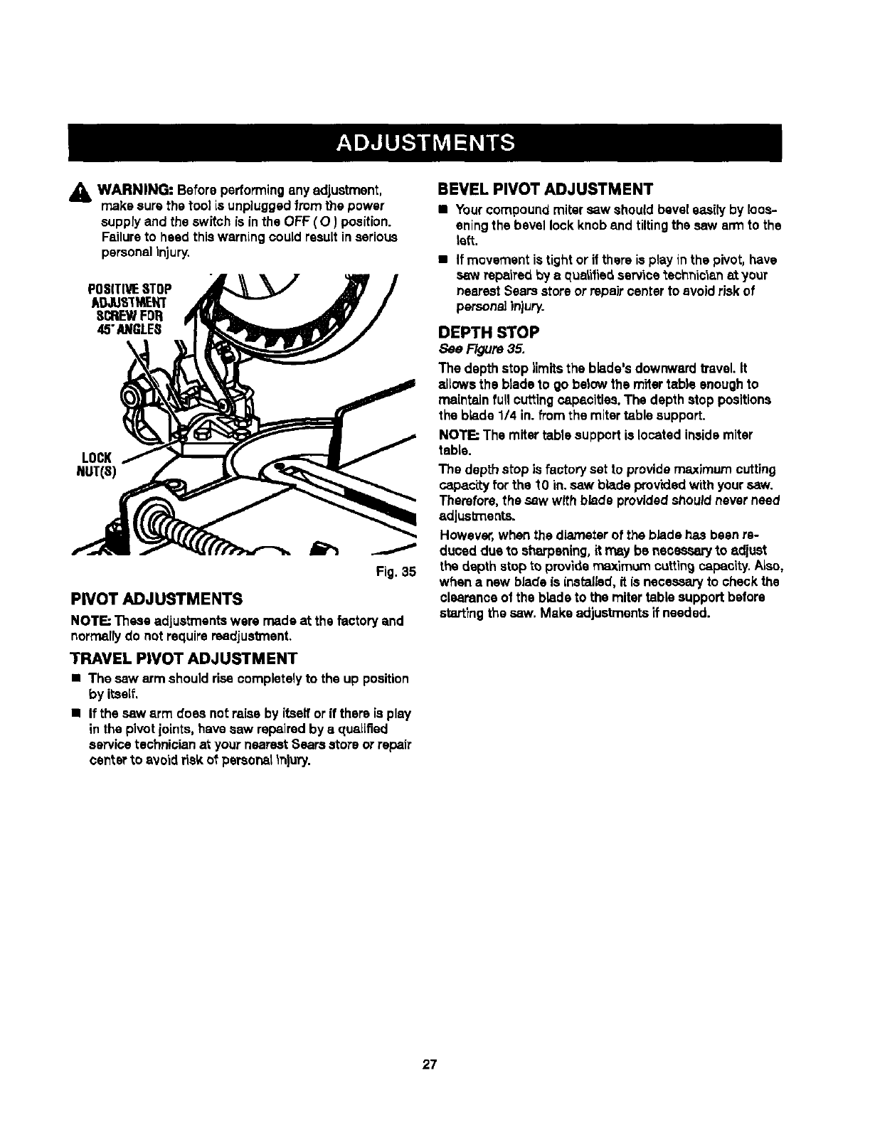
_1_ WARNING: Before performingany adjustment,
make sure the tool is unplugged from the power
supply and the switch is inthe OFF ( O) position.
Failureto heed this warning couldresult inserious
personalinjury.
POSITIVESTOP
ADJLIS'TMENT
SCREWFDR
45"/i_GLE8
LOCK
J
Fig. 35
PIVOT ADJUSTMENTS
NOTE; These adjustmentswere made at the factory and
normallydo not requirereadjustment.
TRAVEL PIVOT ADJUSTMENT
•The saw arm should rise completelyto the up position
by itaeif.
•If the saw arm does not raise by itselfor if there is play
inthe pivot joints, have saw repaired by a qualified
servicetechnician at your nearestSears storeor repair
centerto avoid r_skof personal tn)ury.
BEVEL PIVOT ADJUSTMENT
•Yourcompound mitersaw should beveleasily by loos-
eningthe bevel lock knoband tiltingthe saw arm to the
left.
•If movementis tight or if there is playin the pivot, have
saw repaired by aqualifiedservicetechnician at your
nearestSears storeor repair centerto avoid risk of
personalinjury.
DEPTH STOP
See Figure 35.
The depth stop limits the blade's downward b'avel.It
allows the blade to go balow the rn_artable enough1o
maintain full cuttingsapacitles. The depth stop positions
the blade 1/4 in. from the mitertable support.
NOTE; The miter tablesupport is located insidemiter
table.
The depth stop is factory set to providemaximum cutting
capacity for the "tOin. saw blade providedwith yoursaw.
Therefore,the saw with blade providedshouldnever need
adjusbx_ents.
However,when the diameter of the blade has been re-
duced due to sharpening,it may be necessary to adjust
the depth stop to providemaximum cuttingcapacity. ALso,
when a new blade is installed,it is necessaryto check the
clearanosof the blade to the mitertable supportbefore
start'rngthe saw. Make adjustmentstfneeded.
27
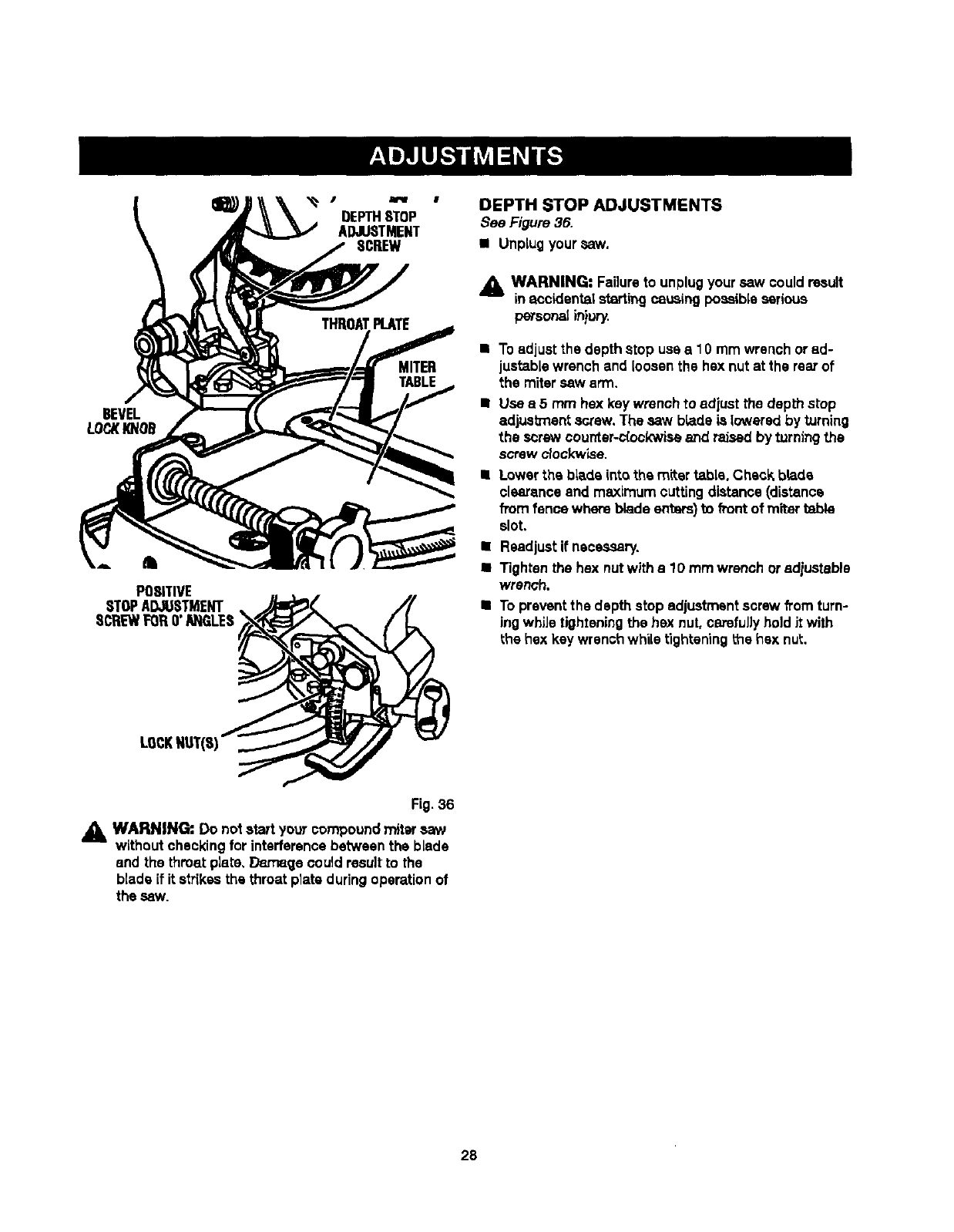
POSITIVE
STOPADJUSTMENT
SCREWFORO"ANGLES
OEPTHSTOP
ADJUSTMENT
8CREW
MITER
TABLE
DEPTH STOP ADJUSTMENTS
See Figure 36.
• Unplugyour saw.
AWARNING" Failureto unplugyoursaw couldresult
inaccidents|startingcausingpossibleserious
personal injury.
•Toadjust the depth atop usaa10 mm wrench or ad-
justablewrench and Loosenthe hex nutat the rear of
the mitersaw arm.
Use a5mm hex keywrench to adiuat the depth stop
adjus_ent screw. The saw h_adele lowered by turning
the screw counter-c[ook'wkseand raised by turningthe
screw clockwise.
Lowerthe blade intothe miter table. Check brads
clsarance and maximumcuttingdistance (distance
fromfence where blade enbars)_ front of miter table
slot.
•Readjustif necessary.
•Tighten the hex nutwith a10 mm wrench or adiustable
wrench.
•Toprevent the depth stop adjustmentscrew fromturn-
ing while tighteningthe hax nut, carefuJ]yholdJtwith
the hax key wrench while tighteningthe hax nut.
LOCKNUT(S)
Fig.36
WARNING:. Do notstart youTcompound mitersaw
without checkingfor interferencebetween the blade
and the throat plate, Damage could resultto the
blade if it strikesthe throat plateduring operation of
the saw.
28
_l_ WARNING: When servicing,use onlyidentical
replacementparts. Use of any other part may create
ahazard or cause productdan'_ge.
AI_ WARNING: Alwayswear safety gogglusorsafety
glasseswith sideshieldsduringpower tool operation
or when blowingdust. If operation is dusty,also
wear a dust mask.
GENERAL
Avoid usingsolvents when cleaning p_sUo parts. Most
plasticsare susceptibleto damage fTomvariousbJpesof
commemialsolventsand m_y be damaged by theirusa.
Use clean clothsto remove dirt, carbon dust, etc.
_IL WARNING: Do not at any time let brake fluids,
gasoline,petroleum-basedproducts,penetrating
oils,etc. come in contact with plastic parts.
Chemicalscan damage, weaken or destroyplastic
which may result inseriouspersonal injury.
It has been found that electric tools are subject to accalar-
ated wear and possibleprernaturelailurawhen they are
used on fiberglassboats, sportscars, wstiboard,spack-
lingcompounds, orplsstar.The chips and grindings_om
these materials are highlyabrasive to electric tool parts
such as bearings,brushes,commutators, etc. Conse-
quently,it is not recommended that this tool be used for
extended work on any fiberglassmaterial,wallboard,
spackJIngcompounds, or piaster.Duringany use on these
materials it is extremelyimportantthat the tool is cleaned
frequently by blowingwith an air iet.
LUBRICATION
Aft of the bearingsin this tool are lubricatedwith asuffi-
cientamount of high grade lubricantfor the lifeof the unit
under normaloperatingconditions.Therefore,no further
lubricationIs requlrad.
_IL WARNING: Toensure safetyand raJJabJJil"_,aJ_
repairs-- with the excaptionof the externally
accessible brushes- should be performed by a
qualifiedservice technicianat a Sears store to avoid
riskof personalinjury.
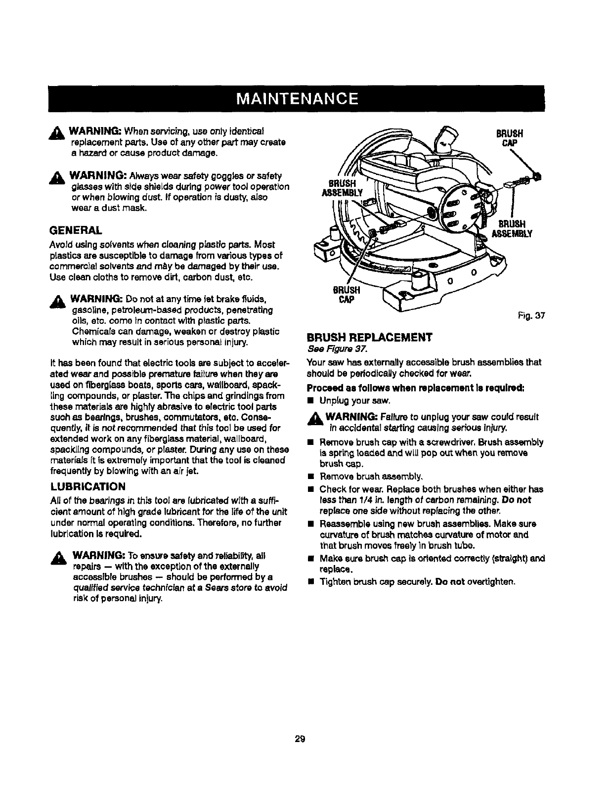
BRUSH
CAP
BRUSH
AESEMBLY
BRUgd-I
ASSEMBLY
BRUSH
CAP
Fig. 37
BRUSH REPLACEMENT
See Figure 37.
Your saw has externallyaccessiblebrush assembliesthat
should be periodicallycheck_edforwear.
Proceed as follows when rapla¢emant Is required:
• Unplugyour saw.
_k WARNING: Failureto unplugyour saw could result
in accidentalstarting causing serious iniury.
•Remove brushcap with ascrewdriver.Brushassembly
is springloaded end wLtlpop outwhen youremove
brush_,ap.
•Remove brush assembly.
•Check for wear. Replace both brusheswhen eitherhas
less than 1/4 in. lengthof carbonremaining.Do not
replace one sidewithout repfacingthe other.
•Reassemble usingnew brushassemblies.Make sure
curvatureof brushmatches curvatureof motor and
that brushmoves freely in brushtubs.
•Make s_'s brushc_ is odented correctly(s_'aight)and
replace.
•"l'ightenbrushcap securely.Do not overtighten.
29

Your Home
For repair-In your home-of all major brand appliances,
lawn and garden equipment, or heating and cooling systems,
no matter who made It, no matter who sold Itl
For the replacement parts, accessories and
owner's manuals that you need to do-it-yourself.
For Sears professional installation of home appliances
and items like garage door openers and water heaters.
1-800-4-MY-HOME ®(1400-469-4663)
Call anytime, day or night (U.S_, and Canada)
_/._81'LCOm re.sears.ca
Our Home
For repair of carry-in items like vacuums, lawn equipment,
and electronics, call or go on-line for the location of your nearest
Sears Parts & Repair Center.
1-800-488-1222
Call anySme, day or night (U,SJ_. only)
_.ZrM_'I_COIR1
To purchase a protectionagreement (U.Sa_.)
or maintenance agreement (Canada) on a productserviced by Sears:
1-800-827-6655 (u.s_.) 1-800-361-6665 (Canada)
Pare pedir servicio de repamci6n
a domicilio, y para ordenar piezas:
1-888.SU.HOGAR s"
(1-888-784-6427 q)
Au Canada pour service en franQais:
1-800-LE-FOYER uc
(1-8oo-533-6937)
WWW.sears.ca
®Reglst8red Tradema_ /_Trademaz-kI_Se_loe Marko__m, RoebuckandCo,
®Marca Regb_ada /"raMarcade FJbdca/=* Marca deServldo de_Hm=, Roel_ck _ _.
_Ma_ue de_mmerce f u" Msro_e d_poz_ede_RoeSucksndCo. ©Seans, Roebuc_snd Co.
