Companion 919327211 User Manual GENERATOR Manuals And Guides L0412363
COMPANION Generator Manual L0412363 COMPANION Generator Owner's Manual, COMPANION Generator installation guides
User Manual: Companion 919327211 919327211 COMPANION GENERATOR - Manuals and Guides View the owners manual for your COMPANION GENERATOR #919327211. Home:Tool Parts:Companion Parts:Companion GENERATOR Manual
Open the PDF directly: View PDF ![]() .
.
Page Count: 28
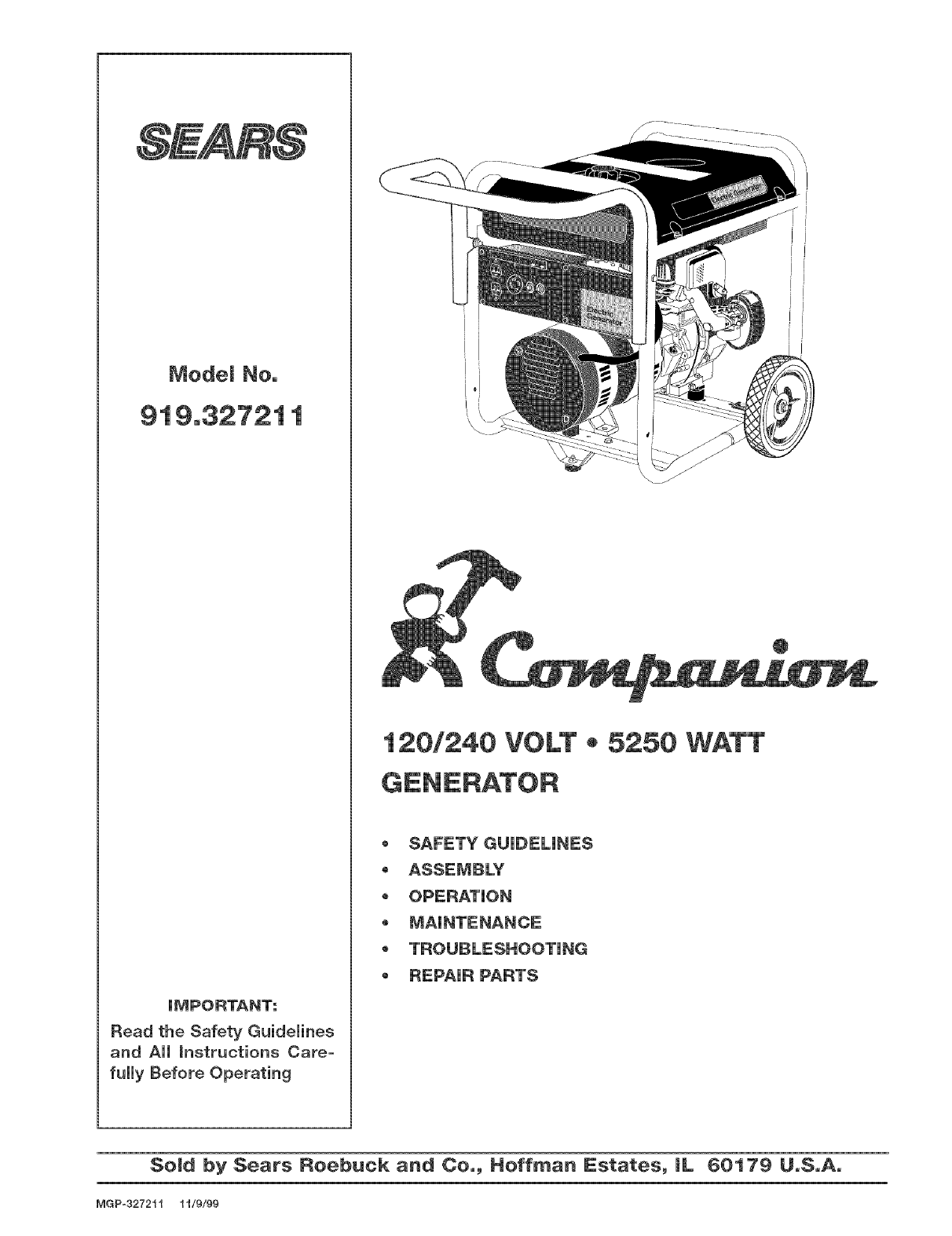
JtVIPORTANT:
Read the Safety Guidelines
and All instructions Care°
fully Before Operating
120/240 VOLT •5250 WATT
,SAFETY GUUDELUNES
oASSEMBLY
- OPERATUON
-MNNTENANCE
- TROUBLESHOOTUNG
REPNR PARTS
I
I
i'
SeBd by Sears Reebuck and Ceo, Heffman Estates, IL 60179 UoSoAo
MGP-32721_ "H/9t99
Warranty .................................................... 2
Safety Guidemines ................................... 3-8
Assembmy ................................................ 9-10
Operation ........................................... 11-14
Maintenance ...................................... 14-16
Service Adjustments .............................. 16
DATE PURCHASED:
MODEL NO:
SERIAL NO:
STORE WHERE PURCHASED:
ADDRESS:
CITY:
TELEPHONE:
Record the above information about your unit
so that you will be abHe to provide it in case of
Hoss or theft.
HORSE POWER 10 HP
GASOLINE CAPACITY 7 GALLON
OIL CAPACmTY 26 OZ. 1
MAmNTENANCE AGREEMENT
The Sears Warranty, pHusa Maintenance Agreement, pro-
vide maximum vaHuefor your Sears products. Contact
your nearest Sears store for detaiHs.
CUSTOMER RESPONSmBmLmTmES
Read and observe the safety ruHes.
Follow a reguHarscheduHe in maintaining, caring for and
using your generator.
Follow the instructions under "Customer Responsibili-
ties" and "Storage" sections of this owner's manual.
FULL ON ==Ym=ARWARRANTY ON S_=AR8 G_=N_=RATOR8
For one year from the date of purchase, when this Sears generator is maintained and operated according to the instruc-
tions in this owner's manual, Sears will repair, free of charge, any defect in material and workmanship.
If your Sears Generator is used for commercial or rental purposes, this warranty applies for only 90 days from the original
date of purchase.
FULL ON ==Ym=ARWARRANTY ON Sm=ARS_=NG|Nm=
For one year from the date of purchase, when this Tecumseh engine is maintained and operated according to the instruc-
tions in this owner's manual, Sears will repair, free of charge, any defect in matedal and workmanship.
If your Tecumseh engine is used for commercial or rental purposes, this warranty applies only for 90 days from the date
of purchase. This warranty does not cover: Expendable items such as spark plugs and air filters, which become worn
during normal use.
Repairs necessary because of operator abuse or negligence, including damage resulting from no oil being supplied to
the engine or failure to maintain the equipment according to the instructions contained in this owner's manual, are not
covered under warranty.
WARRANTY SERVICE IS AVAILABLE BY RETURNING THE GENERATOR TO THE NEAREST SEARS SERVICE CENTER.
This warranty gives you specific legal rights and you may also have other rights, which vary from STATE TO STATE.
$ears_ Roebuck and 0o._ D/817 WAr Hoffman Estates_ |L 60179
MGP327211 2 -- ENG
This manual contains information that is important for you to know and understand. This information relates to
protecting YOUR SAFETY and PREVENTING EQUIPMENT PROBLEMS. To help you recognize this information,
we use the symbols to the right. Please read the manual and pay attention to these sections.
DANGER indicates an imminently hazardous situation
which, if not avoided, will result in death or serious
WARNING indicates a potentially hazardous situation
which, if not avoided, could result in death of serious
CAUTION indicates a potentially hazardous situation
which, if not avoided, _ result in minor or moderate
CAUTION used without the safety alert symbol indicates a
potentially hazardous situation which, if not avoided,
result in rALo43ertydama.qA.
This product is not equipped with a spark arresting muffmer. If the product wiii be used around flammable
materials, or on land covered with materials such as agricultural crops, forest, brush, grass, or other similar items,
then an approved spark arrester must be installed and is legally required in the state of California. It is a violation
of California statutes section 130050 and/or sections 4442 and 4443 of the California Public Resources Code,
unless the engine is equipped with a spark arrestor, as defined in section 4442, and maintained in effective
working order. Spark arresters are also required on some U. S. Forest service land and may also be legally
required under other statutes and ordinances.
This product may contain chemicals known to the state of California to cause cancer, birth defects, or other
reproductive harm. This warning is given in compliance with California Proposition 65, as detectable amounts of
chemicals subject to proposition 65 may be contained in this product.
SAVE THESE iNSTRUCTiONS
When using this product basic precautions should always be
followed including the following:
RBSK OF ELECTROCUTBON AND FBRE
HAZARD WHAT COULD HAPPEN HOW TO PREVENT iT
Attempting to connect generator
directly to the electrical system of
any building structure.
Back feeding electricity through a
building's electrical system to the
outside utility feed lines could en-
danger repair persons attempting to
restore service.
Attempting to connect to the incom-
ing utility service could result in
electrocution.
Restoration of electrical service while
the generator is connected to the
incoming utility could result in a fire or
serious damage if a isolator switch is
not installe&
Failure to use a double throw transfer
switch when connecting to a
structure's electrical system can
damage appliances and WiLL VOID
the manufacturer's warranty.
3 -- ENG
Never backfeed electricity through
a structure's electrical system.
To connect to a structure's electri-
cal system in a safe manner,
always have a Double-Throw
Transfer Switch installed by a
qualified electrician and in compli-
ance with local ordinances. (When
installing a Double=Throw
Transfer Switch, a minimum of
10 gauge wiring must be used,)
MGP 327211
READ AND UNDERSTAND ALL WARNINGS BEFORE
ATTEIVtPTBNG TO OPERATE GENERATOR°
RiSK OF' ELECTROCUTION AND FiRE ,(cont'd)
HAZARD
Operation of generator in rain, wet,
icy, or flooded conditions.
Use of worn damaged, undersized
or ungrounded extension cords.
Placing generator on or against
highly conductive surface, such as
a steel walkway or metal roof.
Improper connection of items to
generator.
Operation of unit when damaged,
or with guards or panels removed.
WHAT COULD HAPPEN
Water is an excellent conductor of
electricity! Water which comes in
contact with electrically charged
components can transmit electricity to
the frame and other surfaces, resultin
in electrical shock to anyone contact-
Contact with worn or damaged
extension cords could result in
electrocution.
Use of undersize extension cords
could result in overheating of the
wires or attached items, resulting in
fire.
Use of ungrounded cordsets could
prevent operation of circuit breakers
and result in electrical shock.
Accidental leakage of electrical
current could charge conductive
surfaces in contact with the generator.
Exceeding the load capacity of the
generator by attaching too many
items, or items with very high load
ratings to it could result in overheating
of some items or their attachment
wiring resulting in fire or electrical
shock.
Attempting to use the unit when it has
been damaged, or when it is not
functioning normally could result in
fire or electrocution.
Removal of guarding could expose
electrically charged components and
result in electrocution.
HOW TO PREVENT iT
Operate generator in a clean, dry,
well ventilated area. Make sure
hands are dry before touching unit.
Inspect extension cords before
use and replace with new cord if
required.
Use proper size (wire gauge)
cordset for application see chart in
the Assembly section of this
manual.
Always use a cordset having a
grounding wire with an appropriate
grounding plug. DO NOT use an
ungrounded plug.
Place generator on low conductiv-
ity surface such as a concrete
slab.
ALWAYS operate generator a
minimum of six feet from any
conductive surface.
Read the load rating chart and
instructions in the Wattage Calcu-
lation section. Make sure that the
summation of electrical loads for
aii attachments does not exceed
the load rating of the generator.
Do not operate generator with
mechanical or electrical problem.
Have unit repaired by an Autho-
rized Service Center.
Do not operate generator with
protective guarding removed.
MGP327211 4 -- ENG
READ AND UNDERSTAND ALL WARNINGS BEFORE
ATTEMPTBNG TO OPERATE GENERATOR.
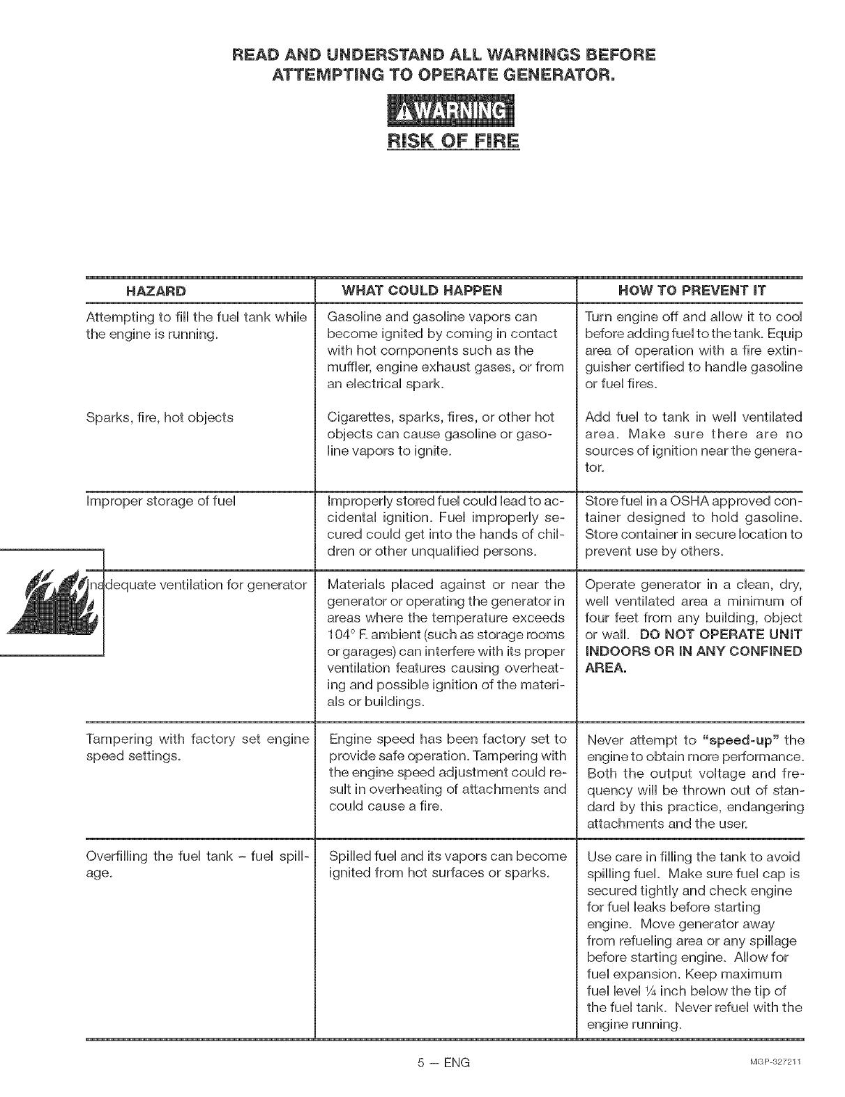
RISK OF FiRE
HAZARD
Attempting to fiii the fuei tank whiie
the engine is running.
Sparks, fire, hot objects
Improper storage of fuel
uate ventilation for generator
Tampering with factory set engine
speed settings.
Overfilling the fuel tank -fuel spilP
age.
WHAT COULD HAPPEN
GasoUine and gasoline vapors can
become ignited by coming in contact
with hot components such as the
muffler, engine exhaust gases, or from
an electrical spark.
Cigarettes, sparks, fires, or other hot
objects can cause gasoline or gaso-
line vapors to ignite.
Improperly stored fuel could lead to ac-
cidental ignition. Fuel improperly se-
cured could get into the hands of chip
dren or other unqualified persons.
Materials placed against or near the
generator or operating the generator in
areas where the temperature exceeds
104° R ambient (such as storage rooms
or garages) can interfere with its proper
ventilation features causing overheat-
ing and possible ignition of the materi-
als or buildings.
Engine speed has been factory set to
provide safe operation. Tampering with
the engine speed adjustment could re-
sult in overheating of attachments and
could cause a fire.
Spilled fuel and its vapors can become
ignited from hot surfaces or sparks.
HOW TO PREVENT iT
Turn engine off and allow it to cool
before adding fuel to the tank. Equip
area of operation with a fire extin-
guisher certified to handle gasoline
or fuel fires.
Add fuel to tank in weii ventilated
area. Make sure there are no
sources of ignition near the genera-
tor.
Store fuel in a OSHA approved con-
tainer designed to hold gasoline.
Store container in secure location to
prevent use by others.
Operate generator in a clean, dry,
well ventilated area a minimum of
four feet from any building, object
or waii. DO NOT OPERATE UNIT
INDOORS OR iN ANY CONFINED
AREA.
Never attempt to "speed=up" the
engine to obtain more performance.
Both the output voltage and fre-
quency will be thrown out of stan-
dard by this practice, endangering
attachments and the user.
Use care in filling the tank to avoid
spilling fuel. Make sure fuel cap is
secured tightly and check engine
for fuel leaks before starting
engine. Move generator away
from refueling area or any spillage
before starting engine. Allow for
fuel expansion. Keep maximum
fuel level 1A inch below the tip of
the fuel tank. Never refuel with the
5-- ENG M@ 327211
READ AND UNDERSTAND ALL WARNINGS BEFORE
ATTEIVtPTBNG TO OPERATE GENERATOR°
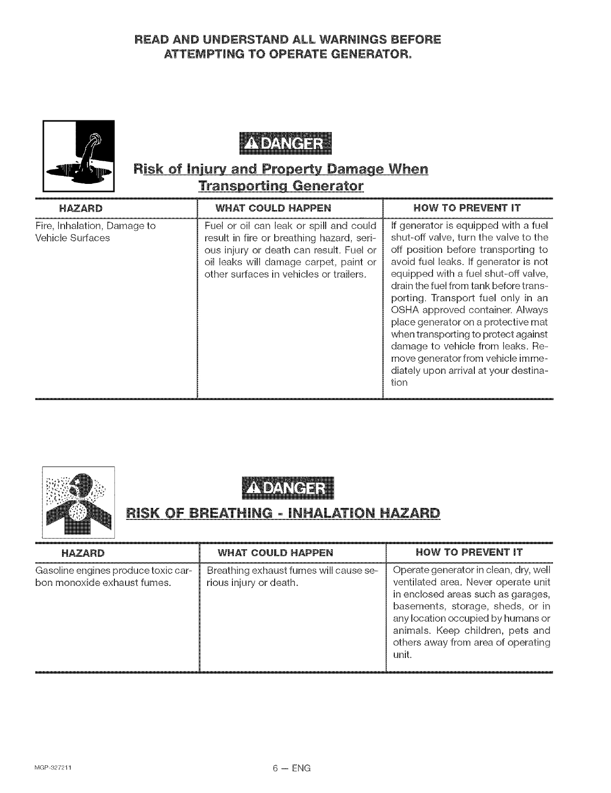
Risk of |niu_ and Prepe_:_ Dama_;_ When
Trans_ Generater
HAZARD
Fire, hhdafion, Damage to
Vehbb Surfaces
WHAT COULD HAPPEN HOW TO PREVENT iT
Fuei or oii can bak or spill and could
result in fire or breathing hazard, seri-
ous injury or death can result. Fuel or
oil leaks will damage carpet, paint or
other surfaces in vehicles or trailers.
If generator is equipped with a fuel
shut-off valve, turn the valve to the
off position before transporting to
avoid fuel leaks. If generator is not
equipped with a fuel shut-off valve,
drain the fuel from tank before trans-
porting. Transport fuel only in an
OSHA approved container. Always
place generator on a protective mat
when transporting to protect against
damage to vehicle from leaks. Re-
move generator from vehicle imme-
diately upon arrival at your destina-
tion
RiSK OF BREATHING - iNHALATiON HAZARD
HAZARD
Gasoline engines produce toxic car-
bon monoxide exhaust fumes.
WHAT COULD HAPPEN
Breathing exhaust fumes will cause se-
rious injury or death.
HOW TO PREVENT iT
Operate generator in clean, dry, well
ventilated area. Never operate unit
in enclosed areas such as garages,
basements, storage, sheds, or in
any iocation occupied by humans or
animals. Keep children, pets and
others away from area of operating
unit.
MGP 327211 6-- ENG
READ AND UNDERSTAND ALL WARNINGS BEFORE
ATTEMPTBNG TO OPERATE GENERATOR°
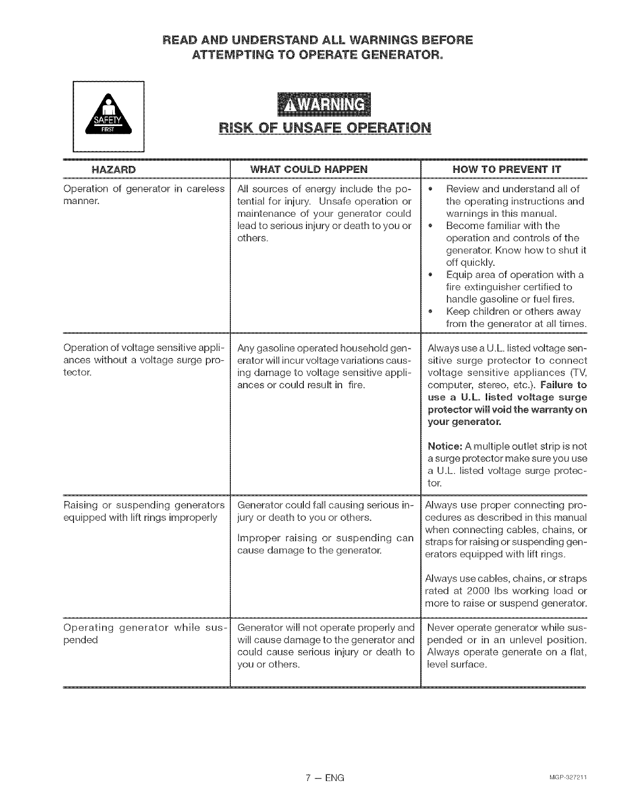
RISK OF UNSAFE OPERATION
HAZARD
Operation of generator in careiess
manner.
Operation of voitage sensitive appii-
ances without a voitage surge pro-
tector.
Raising or suspending generators
equipped with iift rings improperiy
Operating generator while sus-
pended
WHAT COULD HAPPEN
All sources of energy include the po-
tential for injury+ Unsafe operation or
maintenance of your generator could
lead to serious injury or death to you or
others+
Any gasoline operated household gen-
erator wiii incur voltage variations caus-
ing damage to voltage sensitive appli-
ances or could result in fire.
Generator could fall causing serious in-
jury or death to you or others+
Improper raising or suspending can
cause damage to the generatoL
Generator will not operate properly and
will cause damage to the generator and
could cause serious injury or death to
you or others+
NOW TO PREV_'NT iT
+ Review and understand all of
the operating instructions and
warnings in this manual.
+ Become familiar with the
operation and controls of the
generator+ Know how to shut it
off quickly.
+ Equip area of operation with a
fire extinguisher certified to
handle gasoline or fuel fires.
+ Keep children or others away
from the generator at all times+
Always use a U +h listed voltage sen-
sitive surge protector to connect
voltage sensitive appliances (TV,
computer, stereo, etc+)+ Failure to
use a U.L. listed voltage surge
protector will void the warranty on
your generator.
Notice: A multiple outlet strip is not
a surge protector make sure you use
a U+L listed voltage surge protec-
tor+
Always use proper connecting pro-
cedures as described in this manual
when connecting cables, chains, or
straps for raising or suspending gen-
erators equipped with lift rings+
Always use cables, chains, or straps
rated at 2000 Ibs working load or
more to raise or suspend generator+
Never operate generator while sus-
pended or in an unlevel position+
Always operate generate on a fiat,
level surface+
7 -- ENG MGP327211
READ AND UNDERSTAND ALL WARNINGS BEFORE
ATTEMPTBNG TO OPERATE GENERATOR°
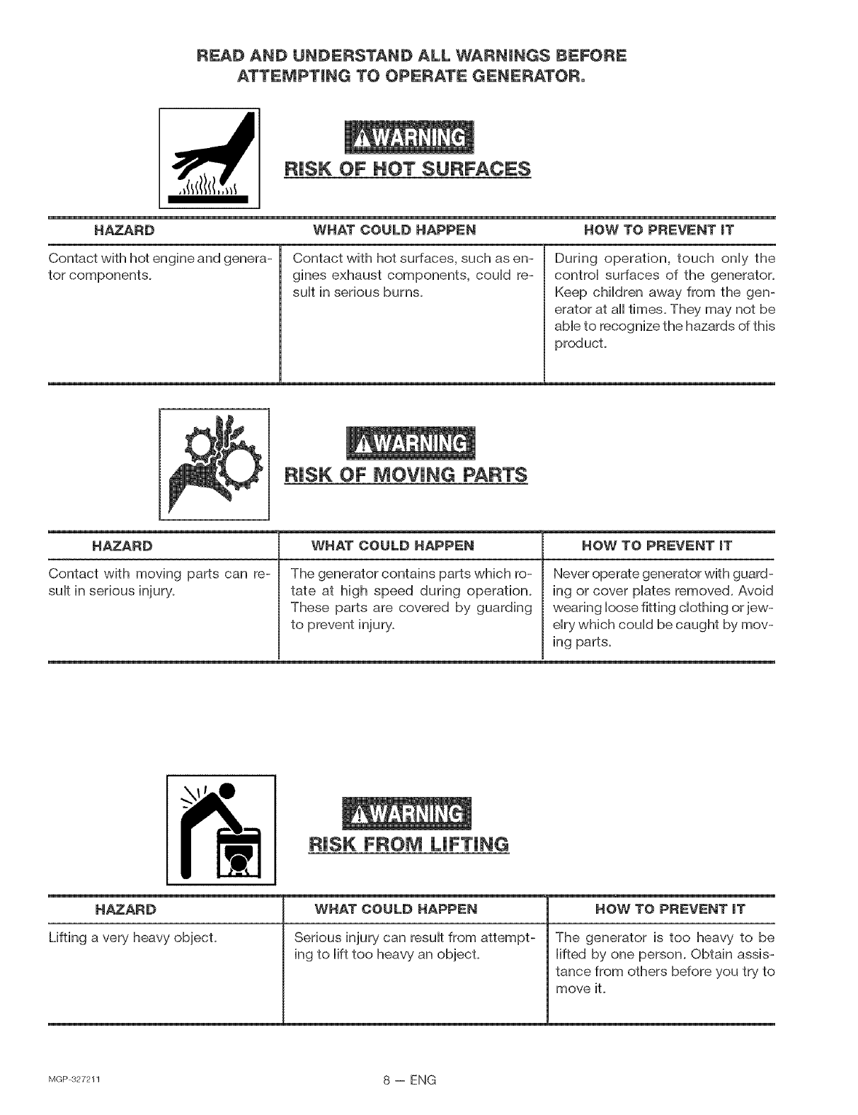
RISK OF NOT SURFACES
HAZARD WHAT COULD HAPPEN HOW TO PREVENT iT
Contact with hot engine and genera-
tor components.
Contact with hot surfaces, such as en-
gines exhaust components, could re-
sult in serious burns.
During operation, touch only the
control surfaces of the generator.
Keep children away from the gen-
erator at all times. They may not be
able to recognize the hazards of this
producL
RiSK OF MOVING PARTS
HAZARD
Contact with moving parts can re-
suit in serious injury.
WHAT COULD HAPPEN
The generator contains parts which ro-
tate at high speed during operation.
These parts are covered by guarding
to prevent injury.
HOW TO PREVENT iT
Never operate generator with guard-
ing or cover plates removed. Avoid
wearing loose fitting clothing or jew-
elry which could be caught by mov-
ing parts.
HAZARD
Lifting a very heavy object.
RiSK FROM LiFTiNG
WHAT COULD HAPPEN
Serious injury can result from attempt-
ing to lift too heavy an object.
HOW TO PREVENT iT
The generator is too heavy to be
lifted by one person. Obtain assis-
tance from others before you try to
move iL
MGP 327211 8-- ENG
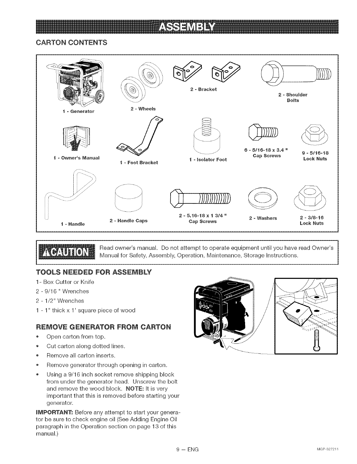
CARTON CONTENTS
2-Wheels
t-Feet Bracket
2o Bracket
t °isolator Feet
2-Shoulder
Belts
6- 5/t6ot8 x3,4 "
Cap Screws
t = Handle
f .........
2=5ot6-t8 x t 3/4 "
Cap Screws 2- Washers 2=3/8-t6
Lock Nuts
Read owner's manual Do not attempt to operate equipment until you have read Owner's
Manual for Safety, Assembly, Operation, Maintenance, Storage Instructions.
TOOLS NEEDED FOR ASSEMBLY
1- Box Cutter or Knife
2 - 9/16 " Wrenches
2-1/2" Wrenches
1-1" thick x 1' square piece of wood
1
REMOVE GENERATOR FROM CARTON
*Open carton from top_
Cut carton along dotted lines.
Remove all carton inserts.
Remove generator through opening in carton.
Using a 9/16 inch socket remove shipping block
from under the generator head. Unscrew the bolt
and remove the wood block. NOTE: It is very
important that this is removed before starting your
generator.
iMPORTANT; Before any attempt to start your genera-
tor be sure to check engine oil (See Adding Engine Oil
paragraph in the Operation section on page 13 of this
manual.)
9 -- ENG MGP327211
GROUND{NG THE GENERATOR
A grounding Hugis suppHied with the generator for use
when required by HocaHeHectricaHordinances. Refer to
article 250 of the NationaH EHectricaHCode to cHarify
any needed grounding information. Your HocaHeHectric
company or a certified eHectrician shouHd be abHeto
heHpyou with this information.
Grounding Lug
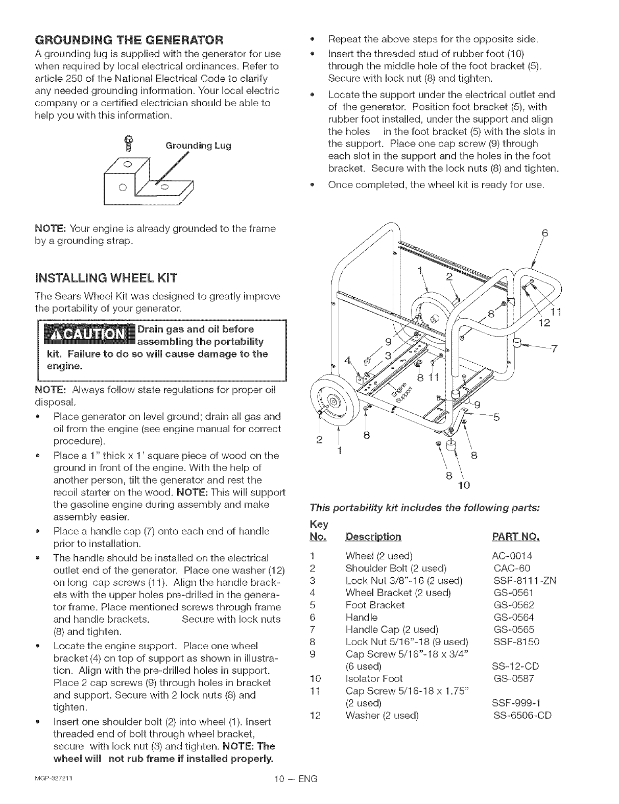
Repeat the above steps for the opposite side.
Insert the threaded stud of rubber foot (10)
through the middHe hoHeof the foot bracket (5).
Secure with lock nut (8) and tighten.
Locate the support under the electrical outlet end
of the generator. Position foot bracket (5), with
rubber foot installed, under the support and align
the holes in the foot bracket (5) with the slots in
the support. Place one cap screw (9) through
each slot in the support and the holes in the foot
bracket. Secure with the lock nuts (8) and tighten.
Once completed, the wheel kit is ready for use.
NOTE: Your engine is already grounded to the frame
by a grounding strap.
mNSTALUNG WHEEL KIT
The Sears Wheel Kit was designed to greatly improve
the portability of your generator.
Drain gas and oimbefore
assembling the portability
kit, Failure to do so will cause damage to the
11
12
NOTE: Always follow state regulations for proper oil
disposal.
Place generator on level ground; drain all gas and
oil from the engine (see engine manual for correct
procedure).
Place a 1" thick x 1' square piece of wood on the
ground in front of the engine. With the help of
another person, tilt the generator and rest the
recoil starter on the wood. NOTE: This will support
the gasoline engine during assembly and make
assembly easier.
Place a handle cap (7) onto each end of handle
prior to installation.
The handle should be installed on the electrical
outlet end of the generator. Place one washer (12)
on long cap screws (11). Align the handle brack-
ets with the upper holes pre-drilled in the genera-
tor frame. Place mentioned screws through frame
and handle brackets. Secure with lock nuts
(8) and tighten.
Locate the engine support. Place one wheel
bracket (4) on top of support as shown in illustra-
tion. Align with the pre-drilled holes in support.
Place 2 cap screws (9) through holes in bracket
and support. Secure with 2 lock nuts (8) and
tighten.
Insert one shoulder bolt (2) into wheel (1). Insert
threaded end of bolt through wheel bracket,
secure with lock nut (3) and tighten. NOTE: The
wheel wimmnot rub frame if installed propermyo
8
8\10
This portability kit includes the following parts:
Key
No. Description PART NO.
1
2
3
4
5
6
7
8
9
10
11
12
Wheel (2 used)
Shoulder Bolt (2 used)
Lock Nut 3/8"-16 (2 used)
Wheel Bracket (2 used)
Foot Bracket
Handle
Handle Cap (2 used)
Lock Nut 5/16"-18 (9 used)
Cap Screw 5/16"-18 x 3/4"
(6 used)
Isolator Foot
Cap Screw 5/16-18 x 1.75"
(2 used)
Washer (2 used)
AC-O014
CAC-60
SSF-8111 -ZN
GS-0561
GS-0562
GS-0564
GS-0565
SSF-8150
SS-12-CD
GS-0587
SSF-999-1
SS-6506-CD
MGP 327211 10 -- ENG
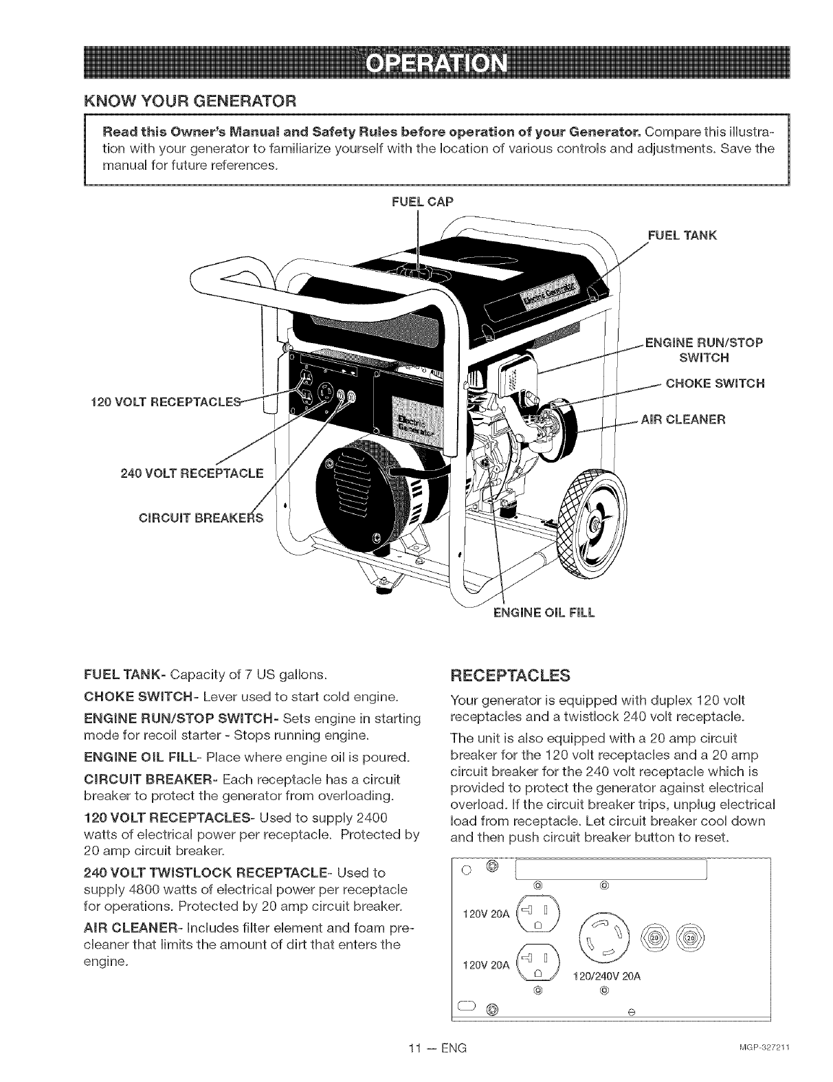
KNOW YOUR GENERATOR
Read this Owner's Manua_ and Safety Ru_es before operation of your Generater, Compare this illustra-
tion with your generator to famiHiarize yourseff with the location of various controls and adjustments. Save the
manual for future references.
FUELCAP
FUEL TANK
120
RUN/STOP
SWITCH
CHOKE SWITCH
CLEANER
240 VOLT RECEPTACLE
ENGINE OiL FiLL
FUEL TANK- Capacity of 7 US gallons.
CHOKE SWITCH- Lever used to start coHdengine.
ENGINE RUN/STOP SWmTCH- Sets engine in starting
mode for recoiHstarter - Stops running engine.
ENGINE OIL NLL- Place where engine oil is poured.
CIRCUIT BREAKER- Each receptacle has a circuit
breaker to protect the generator from overloading.
120 VOLT RECEPTACLES- Used to supply 2400
watts of electrical power per receptacle. Protected by
20 amp circuit breaker.
240 VOLT TWISTLOCK RECEPTACLE- Used to
supply 4800 watts of electrical power per receptacle
for operations. Protected by 20 amp circuit breaker.
AiR CLEANER- hcludes filter element and foam pre-
cleaner that limits the amount of dirt that enters the
engine.
Your generator is equipped with duplex 120 volt
receptacles and a twistlock 240 volt receptacle.
The unit is also equipped with a 20 amp circuit
breaker for the 120 volt receptacles and a 20 amp
circuit breaker for the 240 volt receptacle which is
provided to protect the generator against electrical
overload. If the circuit breaker trips, unplug electrical
load from receptacle. Let circuit breaker cool down
and then push circuit breaker button to reset.
o @
@ @
120V 20A
120V 20A
c2_@
@
120/240V 20A
@
11 -- ENG MGP327211
LOW OraLSHUTDOWN
Your Sears generator engine is equipped with Low Oil
Shutdown. Low Oil Shutdown is a safety device
designed to protect your engine from damage in the
event the oil level in the crankcase is low.
If while the engine is running, the oil gets low, it wiii
automatically shut itself down and wiii not restart until
the oil is added. If the oil is low before start-up, the
generator wiii not start until oil is added.
NOTE: The Low Oil Shutdown mechanism is very sen-
sitive. You must fill the engine to the full mark on the
dipstick to inactivate this safety device.
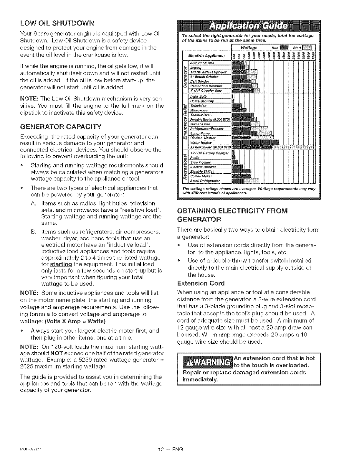
GENERATOR CAPACmTY
Exceeding the rated capacity of your generator carl
result in serious damage to your generator and
connected electrical devices. You should observe the
following to prevent overloading the unit:
Starting and running wattage requirements should
always be calculated when matching a generators
wattage capacity to the appliance or tool.
There are two types of electrical appliances that
can be powered by your generator:
A. Items such as radios, light bulbs, television
sets, and microwaves have a "resistive load".
Starting wattage and running wattage are the
same.
B. Rtemssuch as refrigerators, air compressors,
washer, dryer, and hand tools that use an
electrical motor have an "inductive load".
Inductive load appliances and tools require
approximately 2 to 4 times the listed wattage
for starting the equipment. This initial load
only lasts for a few seconds on start-up but is
very important when figuring your total
wattage to be used.
NOTE: Some inductive appliances and tools wiii iist
on the motor name plate, the starting and running
voltage and amperage requirements. Use the follow-
ing formula to convert voltage and amperage to
wattage: (Volts X Amp = Watts}
Always start your largest electric motor first, and
then plug in other items, one at a time.
NOTE: On 120-volt loads the maximum starting watt-
age should NOT exceed one half of the rated generator
wattage. Example: a 5250 rated wattage generator =
2625 maximum starting wattage.
The guide is provided to assist you in determining the
appliances and tools that can be ran with the wattage
capacity of your generator.
OBTAiNiNG ELECTRiCiTY FROM
GENERATOR
There are basically two ways to obtain electricity form
a generator:
Use of extension cords directly from the genera-
tor to the appliance, lights, tools, etc.
Use of a double-throw transfer switch installed
directly to the main electrical supply outside of
the house.
Extension Cord
When using an appliance or tool at a considerable
distance from the generator, a 3-wire extension cord
that has a 3-blade grounding plug and 3-slot recep-
tacle that accepts the tool's plug should be used. A
cord of adequate size must be used. A minimum of
12 gauge wire size with at bast a 20 amp draw can
be used. When amperage exceeds 20 amps a 10
gauge wire size should be used.
extension cord that is hot
touch is overmoaded.
Repair oF repmace damaged exte_sio_ cords
MGP327211 12 -- ENG
Connecting Generator To Main Electrical
Supply
Potential hazards exist when a eHectricaHgenerator is
connected to the main eHectdcaHsuppHy coming into
the house. It is at that point that the generator couHd
feed back into the utiHitycompany's system causing
possibHe eHectrocufion of workers who are repairing
eHectdcaHHines.To avoid back feeding of eHectdcity into
utility systems, a double-throw transfer switch
should be installed between the generator and utility
power. This device should be installed by a licensed
electrician and in compliance with all local electrical
codes.
NOTE: When installing a Double-Throw Transfer
Switch, a minimum of 10 gauge wiring must be used.
BEFORE STARTmNG ENGmNE
Amways check engine oimmevem
before every start. Running
ine mowof oil or out of oil could result in
serious damage to the engine.
eng
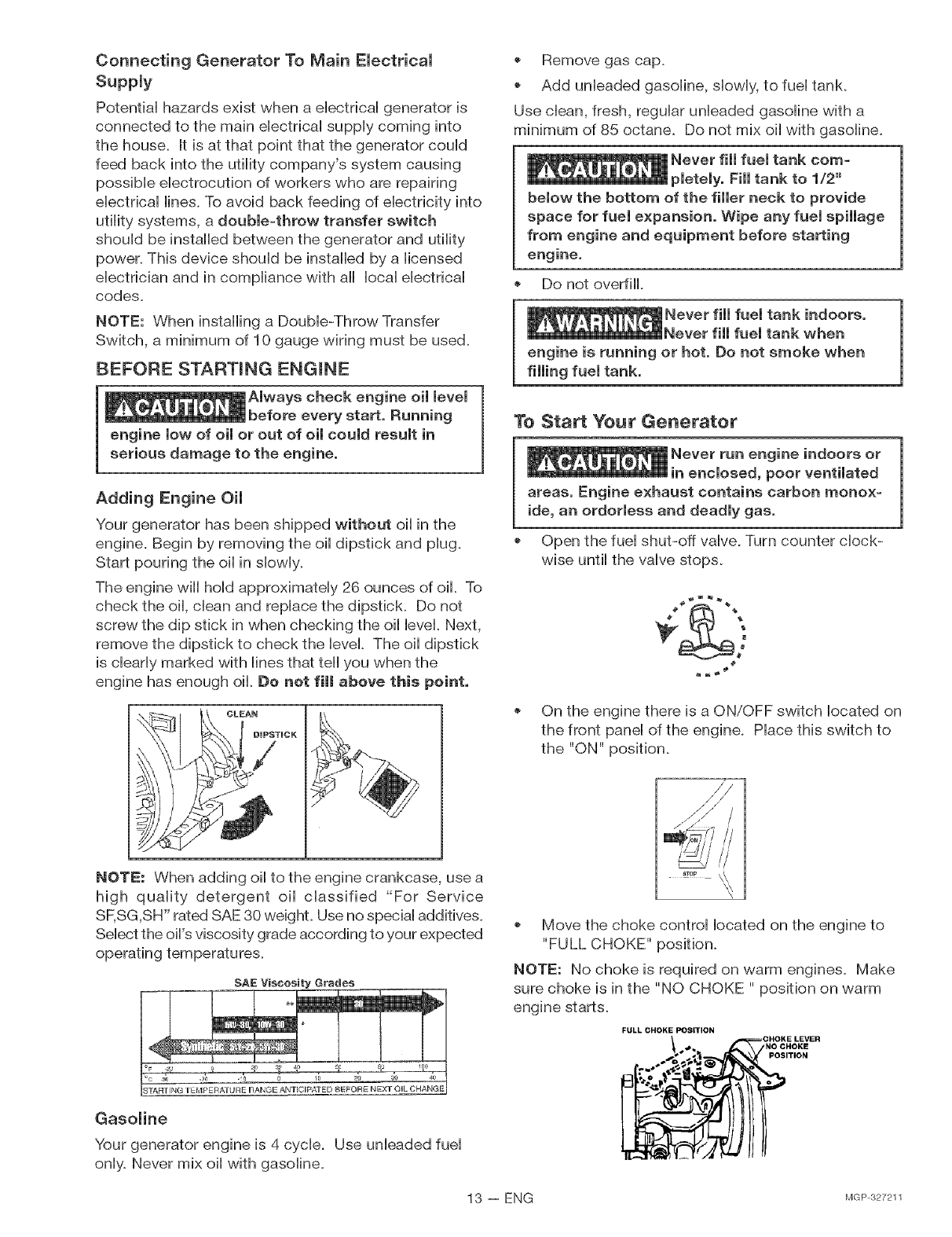
Adding Engine Oil
Your generator has been shipped without oil in the
engine. Begin by removing the oil dipstick and plug.
Start pouring the oil in slowly.
The engine will hold approximately 26 ounces of oil. To
check the oil, clean and replace the dipstick. Do not
screw the dip stick in when checking the oil level. Next,
remove the dipstick to check the level. The oil dipstick
is clearly marked with lines that tell you when the
engine has enough oil. Do net fi_ above this point.
*Remove gas cap.
Add unleaded gasoline, slowly, to fuel tank.
Use clean, fresh, regular unleaded gasoline with a
minimum of 85 octane. Do not mix oil with gasoline.
Never fill fuel tank com-
pletely. Fill tank to 1/2"
below the bottom of the filmer neck to provide
space for fuel expansion. Wipe any fuel spillage
from engine and equipment before starting
Do not overfill.
Never fill fuel tank indoors.
Never fill fuel tank when
engine is running or hot. Do not smoke when
rimmingfuel tank.
To Start Your Generator
indoors or
in enclosed, poor ventilated
areas. Engine exhaust contains carbon monox-
ide, an ordorless and deadly gas.
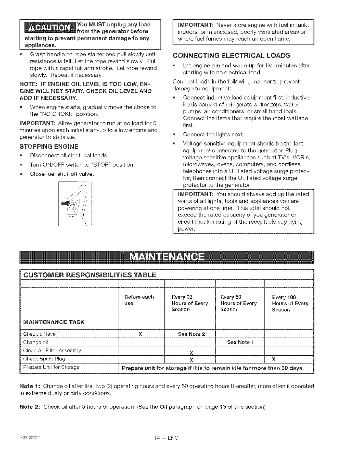
Open the fuel shut-off valve. Turn counter clock-
wise until the valve stops.
4_
On the engine there is a ON/OFF switch located on
the front panel of the engine. Place this switch to
the "ON" position.
NOTE: When adding oil to the engine crankcase, use a
high quality detergent oil classified "For Service
SF,SG,SH" rated SAE 30 weight. Use no special additives.
Select the oil's viscosity grade according to your expected
operating temperatures.
SAE Viseesity Grades
Gasoline
Your generator engine is 4 cycle. Use unleaded fuel
only. Never mix oil with gasoline.
Move the choke control located on the engine to
"FULL CHOKE" position.
NOTE: No choke is required on warm engines. Make
sure choke is in the "NO CHOKE " position on warm
engine starts.
FULL CHOKE POSITION
.o. Ct=;_,"°_o_,_"
13 -- ENG MGP327211
You MUST unplug any load
generator before
starting to prevent permanent damage to any
appliances.
Grasp handle on rope starter and puii slowly until
resistance is felt. Let the rope rewind slowly. Pull
rope with a rapid full arm stroke. Let rope rewind
slowly. Repeat if necessary.
NOTE: mFENGINE OIL LEVEL IS TOO LOW, EN-
GINE WILL NOT START. CHECK OraLLEVEL AND
ADD IF NECESSARY.
*When engine starts, gradually move the choke to
the "NO CHOKE" position.
IMPORTANT: Allow generator to run at no load for 5
minutes upon each initial start-up to allow engine and
generator to stabilize.
STOPPmNG ENGmNE
*Disconnect all electrical loads.
Turn ON/OFF switch to "STOP" position.
Close fuel shut-off valve.
IMPORTANT: Never store engine with fuel in tank,
indoors, or in enclosed, poorly ventilated areas or
where fuel fumes may reach an open flame.
CONNECTmNG ELECTRmCAL LOADS
Let engine run and warm up for five minutes after
starting with no electrical Ioad.
Connect loads in the following manner to prevent
@
o
Connect inductive load equipment first, inductive
loads consist of refrigerators, freezers, water
pumps, air conditioners, or small hand tools.
Connect the items that require the most wattage
first.
Connect the lights nexL
Voltage sensitive equipment should be the last
equipment connected to the generator. Plug
voltage sensitive appliances such at TV's, VCR's,
microwaves, ovens, computers, and cordless
telephones into a UL listed voltage surge protec-
tor, then connect the UL listed voltage surge
protector to the generator_
IMPORTANT: You should always add up the rated
watts of all lights, tools and appliances you are
powering at one time. This total should not
exceed the rated capacity of you generator or
circuit breaker rating of the receptacle supplying
power.
1
CUSTOMER RESPONSBBBLBTBES TABLE
MAINTENANCE TASK
Before each
use
Every 25
Hours of Every
Season
Every 50
Hours of Every
Season
Every 100
Hours of Every
Season
Check oil level X See Note 2
Change oil See Note 1
Clean Air Filter Assembly X
Check Spark Plug X X
Prepare Unit for Storage Prepare unit for storage if it is to remain idle for more than 30 days.
Note f: Change oil after first two (2) operating hours and every 50 operating hours thereafter, more often if operated
in extreme dusty or dirty conditions.
Note £: Check oil after 5 hours of operation (See the Oil paragraph on page 15 of this section)
MGP327211 14 -- ENG
GENERAL RECOMMENDATmONS
The warranty of the generator does not cover items
that have been subjected to operator abuse or negli-
gence. To receive full value from the warranty, opera-
tor must maintain the generator as instructed in this
manual.
Some adjustments wiii need to be made periodically to
maintain your generator.
GENERATOR MAmNTENANCE
Your generator should be kept clean and dry at all
times. The generator should not be stored or oper-
ated in environments that include excessive moisture,
dust or any corrosive vapors, if these substances are
on the generator, clean with a cloth or soft bristle
brush. Do not use a garden hose or anything with
water pressure to clean the generator. Water may
enter the cooling air slots and could possibly damage
the rotor, stator and the internal windings of the
generator head.
All adjustments in the Maintenance section of this
manual should be made at least once each season.
ENGmNE IVIAmNTENANCE
NOTICE: Maintenance, replacement or repair of
the emission control devices and systems may be
performed by any nonroad engine repair establish-
merit or individual, However, to obtain no charge
repairs under the terms and provisions of the
engine manufacturers warranty statement, any
service or emission control part repair or replace-
merit must be performed by a factory authorized
dealer,
Oil
o Oil level should be checked prior to each use and
at bast every 5 hours of operation. To check oil
see Adding Engine oim paragraph in the Operation
section on page 13.
Changing Engine OH
For a new engine, change oil after the first 2 operating
hours. Thereafter, change oil after every 50 hours of
operation.
Change the oil while the engine is still warm. The oil
will flow freely and carry away more impurities. Make
sure the engine is level when filling, checking or
changing oil.
Change the oil as follows:
To keep dirt, grass clippings, etc. out of the
engine, clean the area around the drain plug and
dipstickbefore removing it.
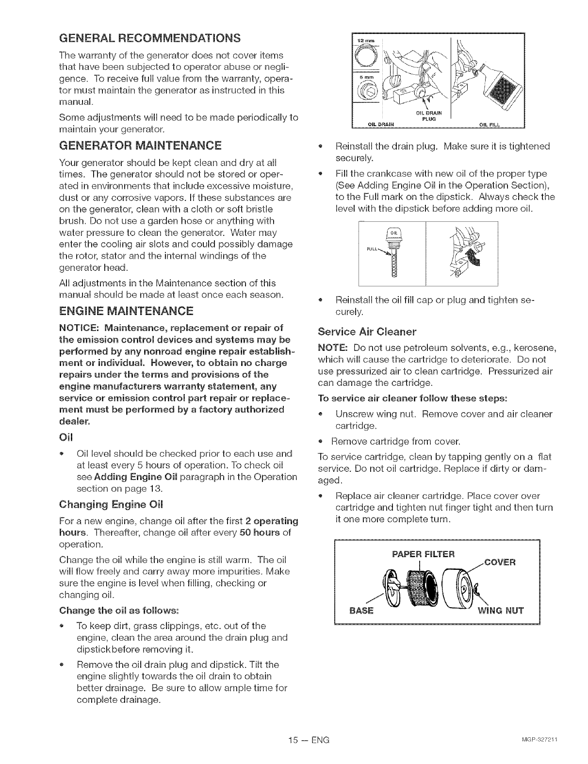
Remove the oil drain plug and dipstick. Tilt the
engine slightly towards the oil drain to obtain
better drainage. Be sure to allow ample time for
complete drainage.
@
@
Reinstall the drain plug. Make sure it is tightened
securely.
Fiii the crankcase with new oil of the proper type
(See Adding Engine Oil in the Operation Section),
to the Fuii mark on the dipstick. Always check the
level with the dipstick before adding more oil.
Reinstall the oil fiii cap or plug and tighten se-
curely.
Service Air Cleaner
NOTE: Do not use petroleum solvents, e.g. kerosene,
which will cause the cartridge to deteriorate. Do not
use pressurized air to clean cartridge. Pressurized air
can damage the cartridge.
To service air cleaner fombw these steps:
Unscrew wing nuL Remove cover and air cleaner
cartridge.
Remove cartridge from cover.
To service cartridge, clean by tapping gently on a fiat
service. Do not oil cartridge. Replace if dirty or dam-
aged.
Replace air cleaner cartridge. Place cover over
cartridge and tighten nut finger tight and then turn
it one more complete turn.
PAPER FILTER
°vER
BASE NG NUT
15 -- ENG MGP327211

Cmean Guard/Muffler
Do not cHeanwith a forcefuH spray of water because
water couHdcontaminate fueHsystem. With a brush or
cHoth dean finger guard after every use to prevent
engine damage caused by overheating. Before running
engine, dean muffHerarea to remove aHHcombustibHe
debris.
CLEAN
Cmean and Repmace Spark Pmug
Check spark pHugyearHy or every 1O0operating hours.
CHeanarea around spark pHug.
Remove and inspect spark pHug.
RepHace spark pHugif eHectrodes are pitted, burned
or porceHain is cracked. For repHacement use
Champion RJ-17M resistor spark pHug.
Check eHectrode gap with wire feeHergauge and
set gap .030 if necessary.
InstaHHspark, tighten secureHy.
,030"(0,76MM)
WIRE GAUGE
CLEAN
CARBURETOR
The carburetor of your generator is pre-set at the fac-
tory. The carburetor shouHdnot be tampered with. if your
generator is used at an aHtitude in excess of 4000 feet
performance may be affected, if so consuHt with your
nearest Sears Service Center regarding high aHtitude set
changes.
GOVERNOR
Your engine governor maintains the constant operating
speed of your generator. 00 NOT tamper with the en-
gine governor which is factory set for proper engine
speed.
Over-speeding your engine above factory high speed set-
ting can be dangerous and couHd possibHy cause per-
sonaH injury or property damage. If you beHievethe en-
gine is running too fast or show, take your generator to a
Authorized Sears Service Center for repair and adjust-
ment.
MGP327211 16 -- ENG
If you are going to store your generator for more than
30 days, use the following information as a guide to
prepare the generator for storage.
Never store generator with
fuel in the tank indoors or
in enclosed, poorly ventilated areas, where
fumes can reach an open flame, spark or pilot
light as on a furnace, water heater, clothes
dryer or other gas appliances.
Engine Preparation
Add fuei stabiiizer to fuei tank to minimize the
formation of fuei gum deposits during storage.
Run engine at bast 10 minutes after adding
stabiiizer to allow it to enter the fuei system.
Disconnect the spark piug wire and remove the
spark piug.
Add one teaspoon of oii through the spark piug
hob.
Hace rag over spark piug hob and pull the recoii a
few times to iubrbate the combustion chamber.
Repiace the spark piug, but do not connect the
spark piug wire.
NOTE: If a fuei stabilizer is not used, all gasoline must
be drained from the tank and carburetor to prevent gum
deposits from forming on these parts and causing pos-
sibb malfunction of the engine.
Generator
Clean the generator as outlined in the Generator
Maintenance paragraph on page 15_
Check that cooling air slots and openings on
generator are open and unobstructed.
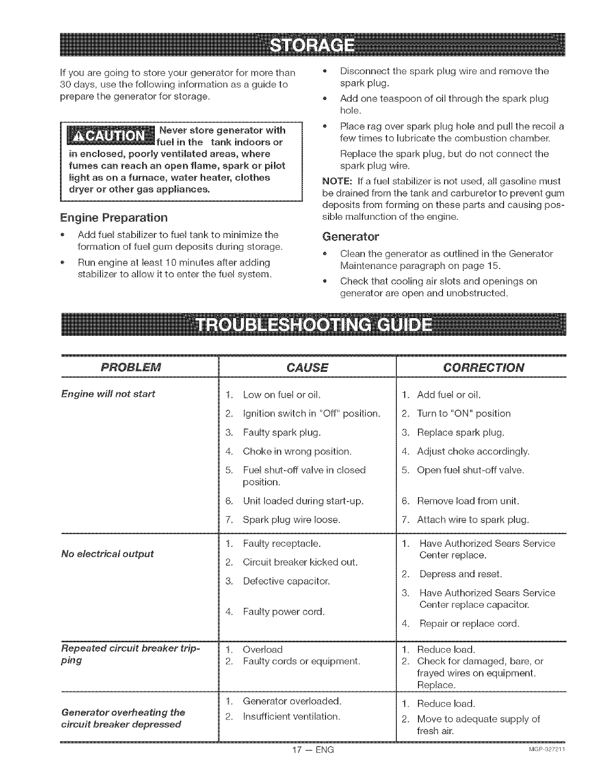
Engine will not start
No electrical output
Repeated circuit breaker trip-
ping
Generator overheating the
circuit breaker depressed
1_ Low on fuel or oil.
2_ Ignition switch in "Off" position.
3_ Faulty spark plug.
4_ Chokein wrong position.
5_ Fuel shut-off valve in closed
position.
6_ Unit loaded during start-up.
7_ Spark plug wire Ioose.
1_ Faulty receptacb.
2_ Circuit breaker kicked ouL
3_ Defective capacitor.
4. Faulty power cord.
1. Overload
2. Faulty cords or equipmenL
1. Generator overloaded.
2. Insufficient ventilation.
1. Add fuel or oii.
2. Turn to "ON" position
3. Replace spark plug.
4. Adjust choke accordingly.
5. Open fuel shut-off valve.
6_
7_
Remove load from unit.
Attach wire to spark plug.
2_
3_
Have Authorized Sears Service
Center replace.
Depress and reseL
Have Authorized Sears Service
Center replace capacitor.
4. Repair or replace cord.
Reduce ioad.
Check for damaged, bare, or
frayed wires on equipmenL
Replace.
,
2_
1. Reduce load.
2. Move to adequate supply of
fresh air.
17 -- ENG MGP327211
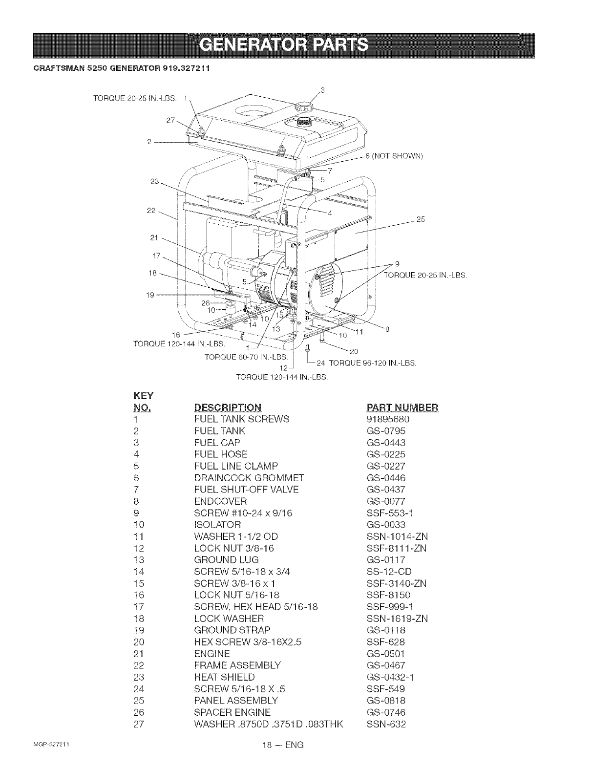
CRAFTSMAN 5250 GENERATOR 919,3272tt
TORQUE 20-25 IN.-LBS. 1
23 _///
22
i.
(NOT SHOWN)
25
UE 20-25 IN.-LBS.
16
TORQUE 120-144 IN.-LBS.
KEY
NO,
1
2
3
4
5
6
7
8
9
10
11
12
13
14
15
16
17
18
19
20
21
22
23
24
25
26
27
"2O
TORQUE 60-70 IN.-LBS. TORQUE 96-120 IN.-LBS.
12
TORQUE 120-144 IN.-LBS.
DESCRiPTiON
FUEL TANK SCREWS
FUEL TANK
FUEL CAP
FUEL HOSE
FUEL LINE CLAMP
DRAINCOCK GROMMET
FUEL SHUT-OFF VALVE
ENDCOVER
SCREW #10-24 x 9/16
ISOLATOR
WASHER 1-1/20D
LOCK NUT 3/8-16
GROUND LUG
SCREW 5/16-18 x 3/4
SCREW 3/8-16 x 1
LOCK NUT 5/16-18
SCREW, HEX HEAD 5/16-18
LOCK WASHER
GROUND STRAP
HEX SCREW 3/8-16X2.5
ENGINE
FRAME ASSEMBLY
HEAT SHIELD
SCREW 5/16-18 X .5
PANEL ASSEMBLY
SPACER ENGINE
WASHER .8750D .3751 D .083THK
PART NUMBER
91895680
GS-0795
GS-0443
GS-0225
GS-0227
GS-0446
GS-0437
GS-0077
SSF-553-1
GS-0033
SSN-1014-ZN
SSF-8111 -ZN
GS-0117
SS-12-CD
SSF-3140-ZN
SSF-8150
SSF-999-1
SSN-1619-ZN
GS-0118
SSF-628
GS-0501
GS-0467
GS-0432-1
SSF-549
GS-0818
GS-0746
SSN-632
MGP 327211 18 -- ENG
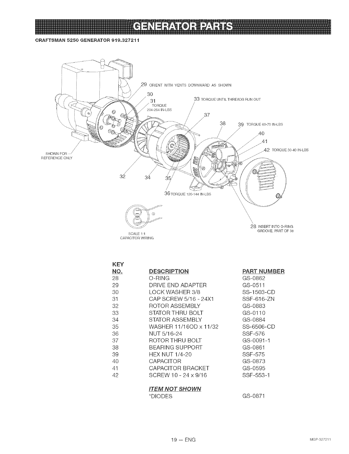
CRAFTSMAN 5250 GENERATOR 9t9o3272tt
SHOWN FOR
REFERENCE ONLY
/
/
/
32 34
x_9 ORIENT WITH VENTS DOWNWARD AS SHOWN
/
/ 30
J 31 33 TORQUE UNTILTHREADS RUN OUT
38 39 TORQUE 60-70 IN-LBS
/
/_40
J_41
_42 TORQUE 30-40 IN-LBS
/
36TORQUE 120-144 IN-LBS
SCALE 1:1
CAPACITOR WIRING
\\\\\
28 INSERT INTO O-RING
GROOVE, PART OF 38
KEY
NO,
28
29
3O
31
32
33
34
35
36
37
38
39
40
41
42
DESCRiPTiON
O-RING
DRIVE END ADAPTER
LOCK WASHER 3/8
CAP SCREW 5/16 - 24Xl
ROTOR ASSEMBLY
STATOR THRU BOLT
STATOR ASSEMBLY
WASHER 11/16OD x 11/32
NUT 5/16-24
ROTOR THRU BOLT
BEARING SUPPORT
HEX NUT 1/4-20
CAPACITOR
CAPACITOR BRACKET
SCREW 10 - 24 x 9/16
ITEM NOT SHOWN
*DIODES
PART NUMBER
GS-0862
GS-0511
SS-1503-CD
SSF-616-ZN
GS-0883
GS-0110
GS-0884
SS-6506-CD
SSF-576
GS-0091-1
GS-0861
SSF-575
GS-0873
GS-0595
SSF-553-1
GS-0871
19 -- ENG MGP327211
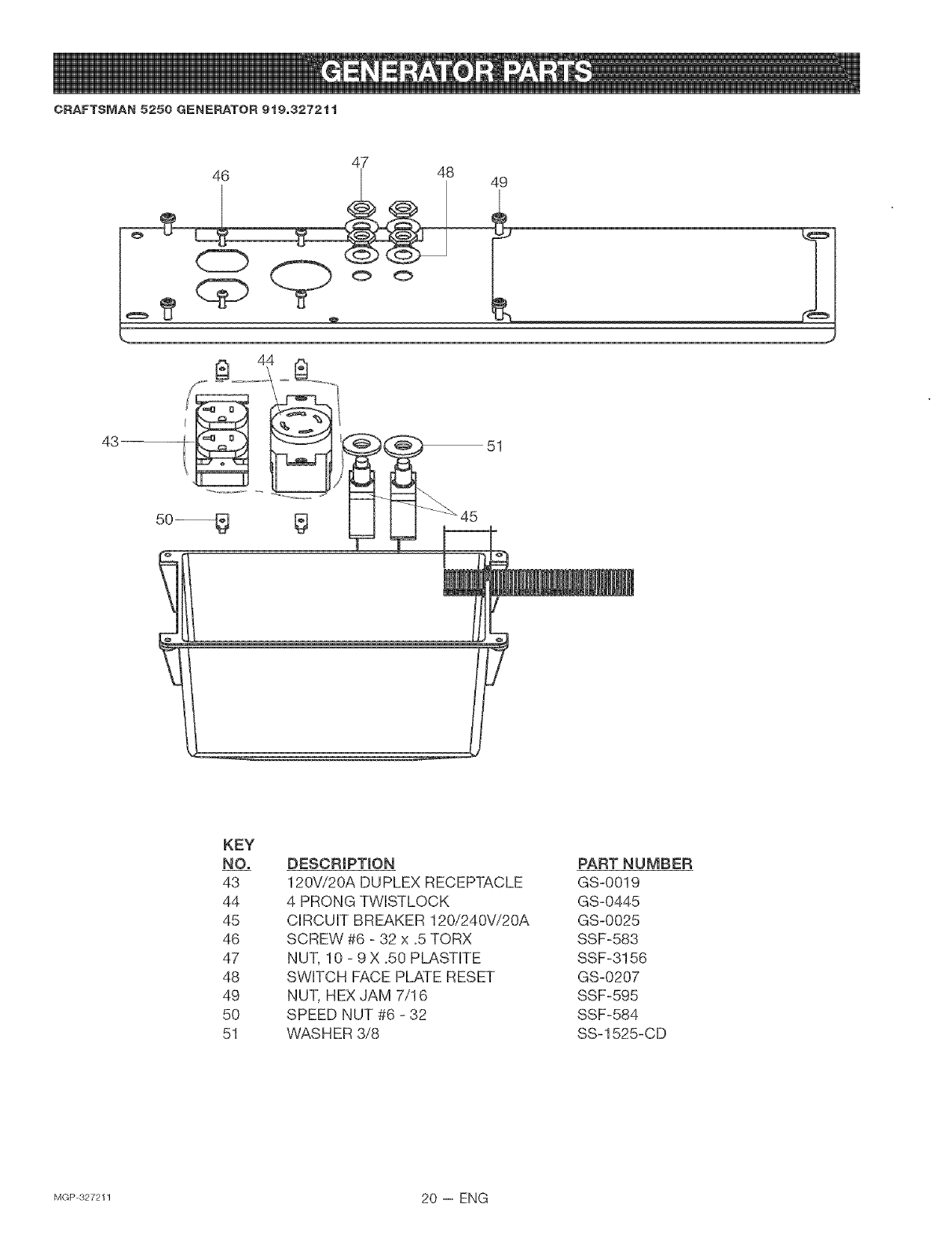
CRAFTSMAN 5250 GENERATOR 919,3272tt
47 48
44
43 51
KEY
NO. DESCRIPTION
43 120Vi20A DUPLEX RECEPTACLE
44 4 PRONG TWISTLOCK
45 CIRCUIT BREAKER 120i240Vi20A
46 SCREW #6 - 32 x _5TORX
47 NUT, 10 - 9 X .50 PLASTITE
48 SWITCH FACE PLATE RESET
49 NUT, HEX JAM 7/16
50 SPEED NUT #6 - 32
51 WAS HER 3/8
PART NUMBER
GS-0019
GS-0445
GS-0025
SSF-583
SSF-3156
GS-0207
SSF-595
SSF-584
SS-1525-CD
MGP327211 20 -- ENG
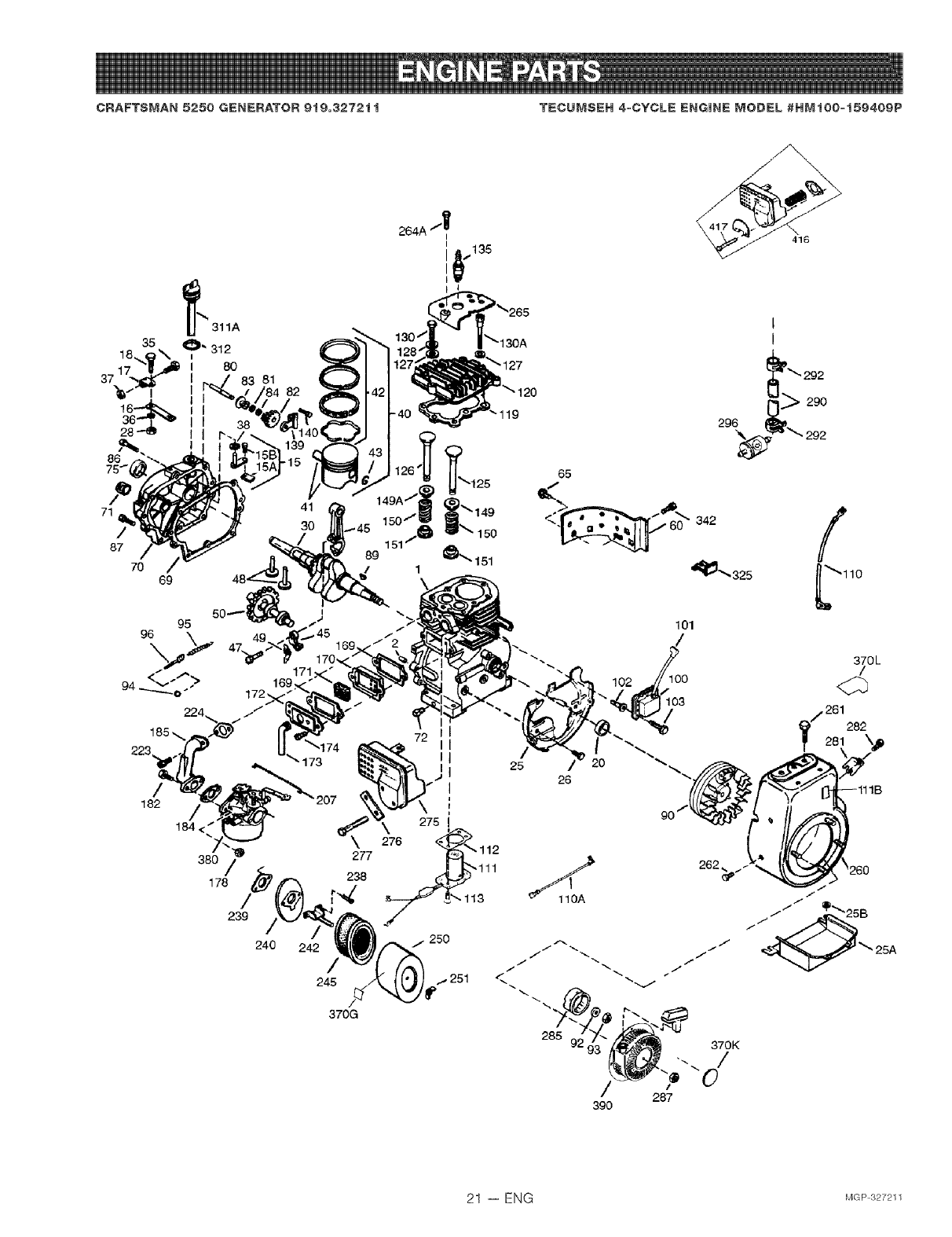
CRAFTSMAN 5250 GENERATOR 919,3272t t TECUMSEH 4=CYCLE ENGINE MODEL #HMt00=t59409P
86
71
/
87
70 69
223
72 I
II
182
184< /%
380 /
178 _
/
239
240
\
277
238
242 /
245
370G
\416
/
_110
370L
/
/261282
_' 281\,p
262
21 -- ENG MGP327211
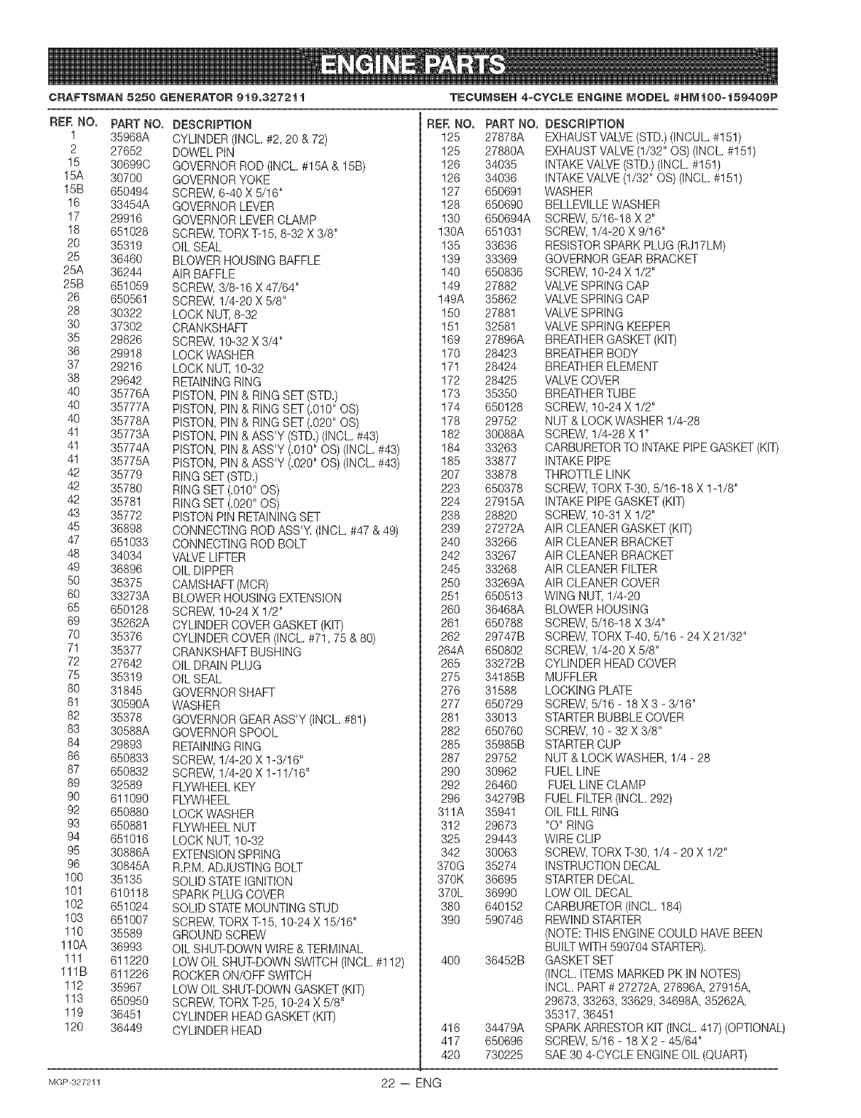
CRAFTSMAN 5250 GENERATOR 9t9=3272t t TECUMSEH 4=CYCLE ENGmNE MODEL #HMtGO=t59409P
REE NO. PART NO.
1 35968A
2 27652
15 30699C
15A 30700
15B 650494
16 33454A
17 29916
18 651028
20 35319
25 36460
25A 36244
25B 651059
26 650561
28 30322
30 37302
35 29826
36 29918
37 29216
38 29642
40 35776A
40 35777A
40 35778A
4! 35773A
41 35774A
41 35775A
42 35779
42 35780
42 35781
43 35772
45 36898
47 651033
48 34034
49 36896
50 35375
60 33273A
65 650128
69 35262A
70 35376
71 35377
72 27642
75 35319
80 31845
8! 30590A
82 35378
83 30588A
84 29893
86 650833
87 650832
89 32589
90 611090
92 650880
93 650881
94 651016
95 30886A
96 30845A
100 35135
101 610118
102 651024
103 651007
110 35589
110A 36993
111 611220
111B 611226
112 35967
113 650950
119 36451
120 36449
DESCRIPTION
CYLINDER (INCL #2, 20 & 72)
DOWEL PiN
GOVERNORROD (tNCL.#15A & 15B)
GOVERNORYOKE
SCREW,6-40 X 5/16"
GOVERNORLEVER
GOVERNORLEVERCLAMP
SCREW,TORX T-15, 8-32 X 3/8"
OIL SEAL
BLOWER HOUSING BAFFLE
AIR BAFFLE
SCREW,3/8-16 X 47/64"
SCREW,1/4-20 X 5/8"
LOCK NUT, 8-32
CRANKSHAFT
SCREW,10-32 X 3/4"
LOCK WASHER
LOCK NUT, !0-32
RETAININGRING
PISTON, PIN & RiNG SET (STD.)
PISTON, PIN & RING SET (.010" OS)
PISTON, PIN & RING SET (=020"OS)
PISTON, PIN & ASS'Y (STD.)(iNCL. #43)
PISTON, PIN & ASS'Y (=010"OS)(INCh #43)
PISTON, PIN & ASS'Y (=020"OS) (INCh #43)
RING SET (STD.)
RING SET (.010" OS)
RING SET (.020" 0%
PISTONPiN RETAININGSET
CONNECTINGROD ASS'Y=(INCL #47 & 49)
CONNECTINGROD BOLT
VALVELIFTER
OIL DIPPER
CAMSHAFT(MCR)
BLOWER HOUSING EXTENSION
SCREW,10-24 X 1/2"
CYLINDER COVERGASKET (KIT)
CYLINDER COVER(INOL #71, 75 & 80)
CRANKSHAFTBUSHING
OIL DRAINPLUG
OIL SEAL
GOVERNORSHAFT
WASHER
GOVERNORGEAR ASS'Y (INOL #81)
GOVERNORSPOOL
RETAININGRING
SCREW,1/4-20 X 1-3/16"
SCREW',1/4-20 X 1-11/16"
FLYWHEELKEY
FLYWHEEL
LOCK WASHER
FLYWHEELNUT
LOCK NUT, !0-32
EXTENSIONSPRING
R.RM. ADJUSTING BOLT
SOLIDSTATEIGNITION
SPARKPLUG COVER
SOLIDSTATEMOUNTING STUD
SCREW,TORX T-15, 10-24 X 15/16"
GROUND SCREW
OIL SHUT-DOWNWIRE& TERMINAL
LOW OIL SHUT-DOWN SWITCH (INOL #112)
ROCKERON/OFF SWITCH
LOW OIL SHUT-DOWN GASKET(KIT)
SCREW,TORX T-25, 10-24 X 5/8"
CYLINDER HEADGASKET (KIT)
CYLINDER HEAD
REE NO. PART NO.
125 27878A
125 27880A
126 34035
126 34036
127 650691
128 650690
130 650694A
130A 651031
135 33636
139 33369
140 650836
149 27882
149A 35862
150 27881
151 32581
169 27896A
170 28423
171 28424
172 28425
173 35350
174 650128
178 29752
182 30088A
184 33263
185 33877
207 33878
223 650378
224 27915A
238 28820
239 27272A
240 33266
242 33267
245 33268
250 33269A
251 650513
260 36468A
26! 650788
262 29747B
264A 650802
265 33272B
275 34185B
276 31588
277 650729
28! 33013
282 650760
285 35985B
287 29752
290 30962
292 26460
296 34279B
311A 35941
312 29673
325 29443
342 30063
370G 35274
370K 36695
370L 36990
380 640152
390 590746
400 36452B
416 34479A
417 650696
420 730225
DESCRIPTION
EXHAUSTVALVE(STD.)(INCUL #! 5!)
EXHAUSTVALVE (1/32" OS) (INCL #151)
INTAKEVALVE(STD.)(INCL #151)
INTAKEVALVE(1/32" OS) (iNCh #151)
WASHER
BELLEVILLEWASHER
SCREW,5/16-18 X 2"
SCREW,1/4-20 X 9/16"
RESISTORSPARK PLUG (RJ17LM)
GOVERNORGEAR BRACKET
SCREW,10-24 X 1/2"
VALVESPRING CAP
VALVESPRING CAP
VALVESPRING
VALVESPRING KEEPER
BREATHERGASKET (KIT)
BREATHERBODY
BREATHERELEMENT
VALVECOVER
BREATHERTUBE
SCREW,10-24 X !/2"
NUT & LOCKVVASHER1/4-28
SCREW,1/4-28 X 1"
CARBURETORTO INTAKEPiPE GASKET(KIT)
INTAKEPIPE
THROTTLELINK
SCREW,TORXT-30, 5/16-18 X 1-1/8"
INTAKEPIPEGASKET (KIT)
SCREW,10-3! X !/2"
AIR CLEANERGASKET(KIT)
AIR CLEANERBRACKET
AIR CLEANERBRACKET
AiR CLEANERFILTER
AIR CLEANERCOVER
WING NUT, 1/4-20
BLOWER HOUSING
SCREW,5/16-18 X 3/4"
SCREW,TORXT-40, 5/16 - 24 X 21/32"
SCREW,1/4-20 X 5/8"
CYLINDER HEADCOVER
MUFFLER
LOCKING PLATE
SCREW,5/16 - 18 X 3 - 3/16"
STARTERBUBBLE COVER
SCREW,10 - 32 X 3/8"
STARTERCUP
NUT & LOCK WASHER, 1/4 - 28
FUEL LINE
FUEL LINECLAMP
FUEL FILTER(INCh 292)
OIL FILL RING
"O" RING
WIRECLIP
SCREW,TORXT-30, 1/4 - 20 X 1/2"
INSTRUCTIONDECAL
STARTERDECAL
LOW OIL DECAL
CARBURETOR(INCL 184)
REWIND STARTER
(NOTE:THIS ENGINE COULD HAVE BEEN
BUILT WITH 590704 STARTER).
GASKET SET
(INCL ITEMS MARKED PK IN NOTES)
iNCh PART# 27272A, 27896A, 27915A,
29673, 33263, 33629, 34698A, 35262A,
35317, 36451
SPARKARRESTORKIT (INCL 417) (OPTIONAL)
SCREW,5/16 - 18 X 2 - 45/64"
SAE30 4-CYCLE ENGINEOiL (QUART)
MGP327211 22 -- ENG
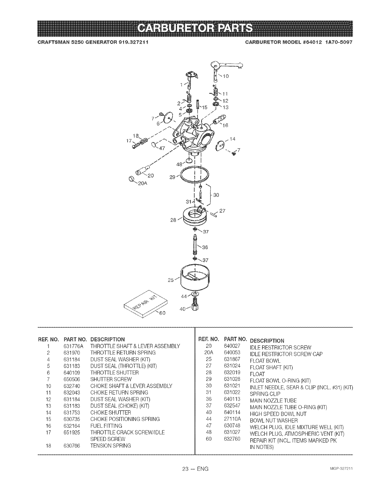
CRAFTSMAN 5250 GENERATOR 919o3272t t CARBURETOR MODEL #64012 tA70=5097
_"-37
25 ,__
RER NO.
1
2
4
5
6
7
10
11
12
13
14
15
16
17
18
PART NO.
631776A
631970
631184
631183
640109
650506
632740
632043
631184
631183
631753
630735
632164
651925
630766
DESCRmPTtON
THROTTLESHAFT& LEVERASSEMBLY
THROTTLERETURNSPRING
DUSTSEAL WASHER(KIT)
DUSTSEAL (THROTTLE)(KIT)
THROTTLESHUTTER
SHUTTERSCREW
CHOKE SHAFT & LEVERASSEMBLY
CHOKE RETURNSPRING
DUSTSEAL WASHER(KIT)
DUSTSEAL (CHOKE) (KIT)
CHOKE SHUTTER
CHOKE POSITIONINGSPRING
FUEL FITTING
THROTTLECRACKSCREW/IDLE
SPEEDSCREW
TENSIONSPRING
RER NO.
20
20A
25
27
28
29
30
3!
36
37
4O
44
47
48
60
PART NO.
640027
640053
631867
631024
632019
631028
631021
631022
640113
632547
640114
27110A
630748
631027
632760
DESCRIPTmON
iDLE RESTRICTORSCREW
iDLE RESTRICTORSCREWCAP
FLOATBOWL
FLOATSHAFT (KIT)
FLOAT
FLOATBOWL O-RING (KIT)
iNLET NEEDLE,SEAR & CLIP (INCh #31) (KIT)
SPRING CLIP
MAIN NOZZLE TUBE
MAIN NOZZLE TUBE O-RING (KIT)
HIGH SPEEDBOWL NUT
BOWL NUT WASHER
WELCH PLUG, IDLE MIXTUREWELL (KIT)
WELCH PLUG,ATMOSPHERICVENT(KIT)
REPAIRKIT (INCL ITEMS MARKEDPK
iN NOTES)
23 -- ENG MGP327211
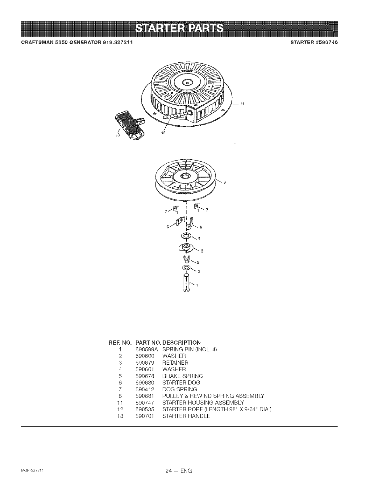
CRAFTSMAN 5250 GENERATOR 9t9o3272t t STARTER #590746
--11
_5
REE NO,
1 590599A
2 590600
3 590679
4 590601
5 590678
6 590680
7 590412
8 590681
11 590747
12 590535
13 590701
PART NO, DESCRIPTION
SPRING PIN dNCL 4)
WASHER
RETAINER
WASHER
BRAKE SPRING
STARTER DOG
DOG SPRING
PULLEY & REWIND SPRING ASSEMBLY
STARTER HOUSING ASSEMBLY
STARTER ROPE (LENGTH 98" X 9/64" DIA=)
STARTER HANDLE
MGP327211 24 -- ENG
CAUFORNIA & US EPA EMISS ON CONTROL WARRAN STATEMENT
The U. S. Environmental Protection Agency ("EPA"), the California Air Resources Board ("CARE}°) and Tecumseh Products Co,
are pBeased to expUain the FederaB and California Emission Control Systems Warranty on your new utility or _awn and garden
equipment engine. UnCalifornia, new 1995 and later utility and Bawnand garden equipment engines must be designed, built and
equipped to meet the State's stringent anti-smog standards, in other states, new 1997 and _ater model year engines must be
designed, built and equipped, at the time of sale, to meet the U,S. EPA regulations for small non=road engines= Tecamseh
Products Co. will warrant the emission control system on your utimityor lawn and garden equipment engine for the periods of time
gisted below, provided there has been no abuse, neglect, unapproved modification, or improper maintenance of your utility or lawn
and garden equipment engine.
Your emission control system may incBudeparts such as the carburetor, ignition system and exhaust system_ Also included may
be the compression releace system end other amissioe-remated assemblies.
Where a warrantable condition exists, Tecumseh Products Co. wilJ repair your utiUityor mawnand garden equipment engine at no
cost to you for diagnosis, parts and Babor.
MANUFACTURER'S EMISS_ON CONTROL SYSTEM WARRANTY COVERAGE
Emission control systems on 1995 and later mode} year California utiBityand lawn and garden equipment engines are warranted
for two years as hereinafter noted. In other states, 1997 and gater model year engines are also warranted for two years. If, during
such warranty period, any emissiomre_ated part on your engine is defective in materials or workmanship, the part will be repaired
or replaced by Tecomseh Products Co.
OWNER'S WARRANTY RESPONSIBILITIES
As the utility or lawn and garden equipment engine owner, you are respensiMe for the performance of the required maintenance
listed in your Owner's Manual but Tecumseh Products Co. will not deny warranty solely due to the lack of receipts or for your
failura to provide written evidence of the performance of aH scheduled maintenance.
As the utitity or lawn and garden equipment engine owner, you sheared,however, be aware that Tecamseh Products Co. may
deny you warracty coverage ifyour utility or lawn and garden equipment or apart thereof has faiUeddue to abuse, neglect,
improper maintenance or unapproved modifications=
You are responsibRe for presenting your uti{ity or lawn and garden equipment engine to a Tecomseh Authorized Service Ooget
(any Tecumseh Registered Service Dealer, Tecemseh Authorized Service Distributor or Tecumseh Centrag Warehouse Distribu-
tor) as soon as a proMem exists. The warranty repairs should be completed in a reasonable amount of time, not to exceed 30
days.
Warranty service can be arranged by contacting either a Tecumseh Authorized Service Outlet or by contacting Tecumseh
Products Co., do Service Manager, Engine and Transmission Group Service Division, 900 North Street, Graftan, WI 53024o1499
Telepbene 1414o377o2700, or see your loca_telephone yeUtowpages under "Engines, Gasoline" for the name, address and
telephone number of a Tecomseh Authorized Service Oueet near you.
iMPORTANT NOTE
This warranty statement expmains your rights and obligations under the Emission Central System Warranty ("ECS Warranty")
which is provided to you by Tecumseh Products Co_ pursuant to California law. Tecumseh Products Co. also provides to original
purchasers of new Tecumseh Products Co. engines. The Tecumseh P[oducts Co. Limited Warranties for New Tecumseh Engine
and E_ectranic Ignition Medules ("Tecumseh Products Co. Warranty") which is enclosed with aDOnew Tecumseh Products Co.
engines on a separate sheet= The ECS Warranty applies onty to the emission central system of your new engine. To the extent
that there is any conflict in terms between the ECS Warranty and the Tecumseh Products Co, Warranty, the ECS Warranty shah
appDyexcept in any circumstances in which the Tecumseh Products Co. Warranty may provide a longer warranty period. Both
the ECS Warranty and the Tecumseh Products Co. Warranty describe important rights and obligations with respect to your new
engine,
Warranty service ¢8n only be performed by a Tecumseh Products Co. A_'thodzed Service Outmet,or by Tecamaeh Products Co.
at its f_c_ery in Graffon, WL At the time of requesting warranty service, evidence must be presented of the date of sale to the
original purchaser. The purchaser shaU pay any charges for making service calls and/or for transporting the preducts to and from
the p_ac8where the inspe{;tionand/or warranty work is pedormed. The purchaser shal_ be responsible for any damage or Ions
tnc_n_i _nconn_en w_ _ transportation of any engine or any part(s) thereof submitted for inspection and/or warranty w_k.
if you have _y q_sti_ns re_ar_ing year warranty rights and responsibilities, you should contact Tec_mseh Pred_'ts Ca. at
1.414-377_2700.
25 -- ENG MGP327211
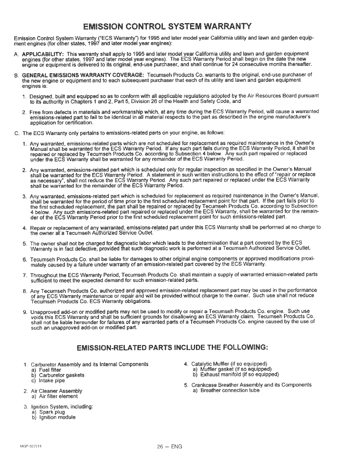
EMISSION CONTROL SYSTEM WARRANTY
Emission CentrM System Warranty ("ECS Warranty") for 1995 and later modemyear California utility and lawn and garden equip-
ment engines (for other states, 1997 and later model year engines):
A. APPLICABILITY: This warranty shah apply to 1995 end later mode_ year California utility and lawn and garden equipment
engines (for ether states, 199"7 and _ater model year engines). The ECS Warranty Period shah begin on the date the new
engine or equipment is deBivered to its original end-use purchaser, and sha_Jcontinue for 24 consecutive months thereafter.
B, GENE_AL EMISSIONS WARRANTY COVEPJkGE: Tecumseh Products Co. warrants te the original, end=use purchaser ef
the new engine or equipment and to each subsequent parchaser that each of its utility and Uawnand garden equipment
engines is:
1. Designed, built and equipped so as to conform with aH applicab}e regulations adopted by the Air Resources Board pursuant
te its authority in Chapters 1 and 2, Part 5, Division 26 ef the Heaffh and Safety Code, and
2. Free from defects in materials and workmanship which, at any time during the ECS Warranty Period, wita cause a warranted
emissiens=rMated part to fail to be identical in auramaterial respects to the part as described in the engine manufacturer's
applicationfor certification.
C. The ECS Warranty only pertains to emissions-remated parts on your engine, as follows:
1. Any warranted, emissions-remated parts which are not scheduJed for replacement as required maintenance in the Owner's
Manuamshall be warranted for the ECS Warranty Period. If any such part fails during the ECS Warranty Period, it shall be
repairedor repmacedby Tecumseh ProductsCo, accordingto Subsection4 beMw, Any such partrepairedor replaced
under the ECS Warranty shah be warranted for any remainder of the ECS Warranty Period.
2. Any warranted, emissions-related part which is scheduled onByfor regainerinspection as specified in the Owner's Manuam
shaJmbe wan'anted for the ECS Warranty Period. A statement in such written instructions to the effect of "repair or replace
as necessary, shah not reduce the ECS Warranty Period. Any such part repaired or reptaced under the ECS Warranty
shamlbe warranted for the remainder of the ECS Warranty Period.
3, Any warranted, emissions-related part which is scheduled for replacement as required maintenance in the Owner's Manual,
shal_ be warranted for the period of time prior to the first scheduled replacement point for that part. If the part fai_s prior to
the first scheduled replacement, the part shah be repaired or repBaced by Tesumseh Products Co. according to Subsection
4 beMw. Any such emissions-related part repaired or replaced under the ECS Warranty, shall be warranted for the remain-
der of the ECS Warranty Period prior to the first scheduled replacement point for such emissions-related part=
4. Repair or replacement of any warranted, emissions°related part under this ECS Warranty shall be performed at no charge to
the owner at a Tecumseh Ad_Bti2ed S_rv_ce Outlet. - -
5. The owner shah not be charged for diagnostic labor which Mads to the determination that a part covered by the ECS
Warranty is in fact defective, provided that such diagnostic work is performed at a Tecumseh Authorized Service Outlet,
B. Tecumseh Products Co. shall be tiable for damages to other odginal engine components or approved modifications proxi-
matemycaused by a failure under warranty of an emission-related part covered by the ECS Warranty.
7. Throughout the ECS Warranty Period, Tecumseh Products Co. shall maintain a supply of warranted emission-related parts
sufficient to meet the expected demand for such emission-related parts.
8. Any Tecumseh Products Co. authorized and approved emission-related replacement part may be used in the performance
of any ECS Warranty maintenance or repair and will be provided without charge to the owner. Such use shall not reduce
Tecamseh Products Co. ECS 'Warranty obligations.
9. Unapproved add_on or modified parts may not be used to modify or repair a Tecumseh Products Co. engine. Such use
voids this EOS Warranty and shah be sufficient grounds for disallowing an ECS Warranty claim. Tecumseh Products Co.
shatl not be liable hereunder for failures of any warranted parts of a Tecumseh Products Co. engine caused by the use of
such an unapproved add-on or modified part.
EiM_SS_ONoRELATED PARTS iNCLUDE THE FOLLOWING:
1, Carburetor Assembly and its Internal Components
a) Fue_fiffer
b) Carburetor gaskets
c) Mtake pipe
2. Air Cleaner Assembly
a) Air filter element
3. _gnition System, including:
a) Spark plug
b) Ignition module
4. Cata_yfic Muffler (if so equipped)
a) Muffler gasket (if so equipped)
b) Exhaust manifold (if so equipped)
5. Crankcase Breather Assembly and its Components
a) Breather connection tube
MGP327211 26 -- ENG

27-- ENG MGP327211

For in-home major brand repair service:
Call 24 hours a day, 7 days a week
1-800-4-MY-HOME _M c_-800-469-4663_
Para pedir servicio de reparaci6n a domiciHo _ 1-800-676-5811
In Canada for all your service and parts needs call -- 1o800o665o4455
Au Canada pour tout le service ou les pieces
For the repair or repJacement parts you need:
Call 6 am - 11 pm CST, 7 days a week
Parts Direct TM
1-800-366- PART (1-800-366-7278_
Para ordenar piezas con entrega a domiciHo -- l t800-1659-7084
For the Jocation of a Sears Parts and Repair Center in your area:
Call 24 hours a day, 7 days a week
1-800-488-1222
For information on purchasing a Sears Maintenance Agreement
or to inquire about an existing Agreement:
Call 9 am _ 5 pro, Monday _ Saturday
1-800-827-6655
SE/A/ S
HomeCentral °°
MGP 327211
