Compex Systems 06-WLM54AGP23 Wireless-AG 23dBm Network Mini PCI Adapter User Manual
Compex Systems Pte Ltd Wireless-AG 23dBm Network Mini PCI Adapter Users Manual
Users Manual
*****Caution*****
Changes or modifications not expressly approved by the
party responsible for the compliance could void the user’s
authority to operate the equipment.
***** FCC Statements*****
This device complies with part 15 of the FCC Rules.
Operation is subject to the following two conditions: (1) This
device may not cause harmful interference, and (2) this device
must accept any interference received, including interference
that may cause undesired operation.
This device is intended only for OEM integrators under the following conditions:
1) The antenna must be installed such that 20 cm is maintained between the
antenna and users. For laptop installations, the antenna must be installed to
ensure that the proper spacing is maintained in the event the users places the
device in their lap during use (i.e. positioning of antennas must be placed in the
upper portion of the LCD panel only to ensure 20 cm will be maintained if the user
places the device in their lap for use), and
2) The transmitter module may not be co-located with any other transmitter or
antenna. As long as the 2 conditions above are met, further transmitter test will not
be required. However, the OEM integrator is still responsible for testing their
end-product for any additional compliance requirements required with this module
installed (for example, digital device emissions, PC peripheral requirements, etc.).
IMPORTANT NOTE:
In the event that these conditions can not be met (for example certain laptop
configurations or co-location with another transmitter), then the FCC authorization
is no longer considered valid and the FCC ID can not be used on the final product.
In these circumstances, the OEM integrator will be responsible for re-evaluating
the end product (including the transmitter) and obtaining a separate FCC
authorization.
End Product Labeling:
This transmitter module is authorized only for use in device where the
antenna may be installed such that 20 cm may be maintained between the
antenna and users (for example access points, routers, wireless ADSL modems,
certain laptop configurations, and similar equipment). The final end product must
be labeled in a visible area with the following:
"Contains ".
Manual Information for End Users
The end user must not have manual instructions to remove or install the
device. The user manual for end users must include the following information in a
prominent location.
"IMPORTANT NOTE:
To comply with FCC RF exposure compliance requirements,
the antenna used for this transmitter must be installed to
provide a separation distance of at least 20 cm from all persons
and must not be co-located or operating in conjunction with
any other antenna or transmitter."
Quick Install Guide
Compex
Wireless-AG 23 dBm Network
Mini PCI Adapter
WLM54AGP23
Version 1.1
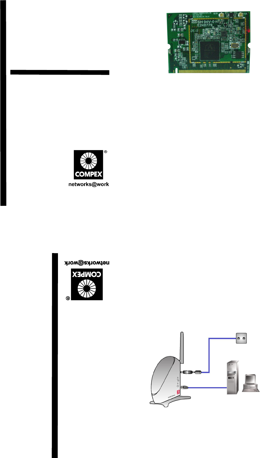
1. Introduction
This mini PCI adapter, Compex WLM54AGP23 contains a dual-mode
single chip MAC/BB/Radio for IEEE 802.11a, 11g and 11b Wireless
LAN. It can support high-speed data transmission of up to 54Mbps in
the 2.4GHz and 5GHz frequency bands based on 802.11b/g and
802.11a mode respectively.
Based on the latest industry standard Wi-Fi Certified IEEE
802.11a/b/g specification, the Compex WLM54AGP23 offers maximum
channel speeds of up to 54 Mbps. It supports key security features
like Wi-Fi Protected Access (WPA), WPA2, WEP and 802.1x.
You can find this adapter that is seated inside the wireless products
such as the WPE54AG. WLM54AG can be removed from or inserted
onto the PCBA of the WPE54AG.
2. Package Content
Compex WPE54AG retail package contains the following items:
•1 x Compex WPE54AG
•1 x External Power Adapter
•1 x 3dBi SMA Antenna
•1 x Base Stand
•1 x RJ45 MDIX cross-over Ethernet cable
•1 x Quick Install Guide with Warranty Registration Form
•1 x Product CD (including Quick Install Guide, User’s Manual,
Firmware Recovery Tool & Utilities)
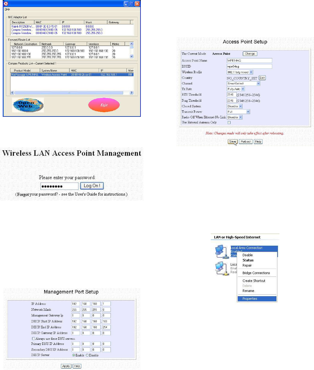
3. Hardware Installation
1. Connect one end of the RJ45 crossover Ethernet cable to your
PC and another end to the Ethernet port of your Compex
WPE54AG.
2. Next, attach the power adapter supplied in the packaging to the
power point.
3. Connect the power plug onto the socket on your Compex
WPE54AG.
4. Power ON your Compex WPE54AG and your PC. Notice that
the LAN Link/ACT and Power LEDs have lighted up. This
indicates that the connection has established successfully
between your Compex WPE54AG and your PC.
NETPASSAGE
PC
Power Point
RJ45
Ethernet cable
Compex
WPE54AG
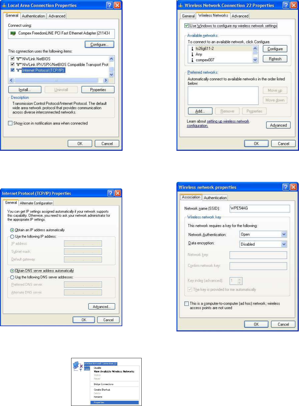
4. Access to Web-based Interface
Compex has developed a powerful uConfig utility which provides
you hassle-free access to the web-based configuration page. To do so,
simply
1. Insert your Product CD into your CD-ROM drive. Go to
Utilities section and select uConfig to run the program.
2. The following screen shot will appear. Select NetPassage
WPE54AG and click on OpenWeb button to access to the
authentication page.
3. The password is pre-configured as password in the field
provided. Click on Log On! button to access to the main page.
After accessing to the main page of your Compex WPE54AG, you
can start doing your configuration
5. Basic Configuration for Compex WPE54AG
1. To handle automatic IP addressing, go to Management Port
under CONFIGURATION section.
2. Go to DHCP Server option and select Enable radio button.
Click on Apply button to update the changes.
Now, your Compex WPE54AG acts as a DHCP Server which can
assign IP address to your PC/clients.
6. WLAN Basic Setup for Compex WPE54AG
1. To configure your Compex WPE54AG for your wireless user,
go to WLAN Basic Setup from the CONFIGURATION
section.
2. From your Access Point Setup window, key in the ESSID that
you intend to use for your wireless network.
3. You may leave the frequency channel as SmartSelect. This
allows your access point to select the channel automatically.
4. Leave the remaining settings as default and click Apply button
to update the changes.
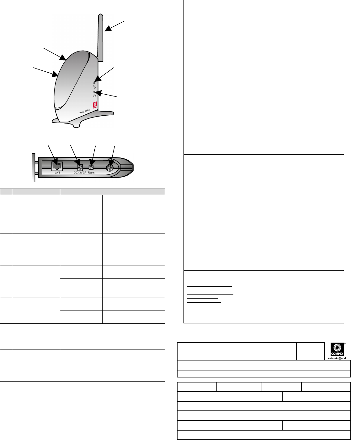
7. TCP/IP Configuration for wireless clients
Generally, automatic IP addressing should be configured for your
wireless client PCs or notebooks. You may configure the TCP/IP
settings of Microsoft windows XP as follows:
1. From your desktop, right click on My Network Places and
select Properties.
2. Next, right click on your Ethernet Adapter go to Properties.
3. Highlight Internet Protocol (TCP/IP) and click on Properties
button.
4. Select the radio buttons for Obtain an IP address
automatically and Obtain DNS server address automatically.
Click OK button to update the changes.
Next, you may set up Windows XP’s Wireless Network Connection
as follows:
5. Right click on Wireless
Network Connection
corresponding to the Wireless
Ethernet Adapter you wish to
connect to your Compex
WPE54AG, and click on
Properties.
6. Go to Wireless Networks tab and click on Add.. button.
7. Next, enter the Network name (SSID) which must be the same
as the ESSID that you input earlier for your access point.
Ensure that the Network name (SSID) value is the same for all
wireless clients in the same wireless network.
For now, you may leave the other information as its default settings.
Network Authentication: Open
Data encryption: Disabled
For details in configuring your Compex WPE54AG, kindly refer to
the User’s Manual stored in the Product CD.
8. Panel Views and Descriptions
Features Status and Indications
1 LAN Link/Act
LED Steady Yellow Compex WPE54AG is
operating at the speed
of 10Mbps.
Steady Green Compex WPE54AG is
operating at the speed
of 100Mbps.
2 WLAN Link/Act
LED Steady Green More than 1 wireless
client is present in the
wireless network.
Blinking Green Activity is detected in
the wireless network.
3 Diagnostic LED Steady Green The device is in access
point or gateway mode.
Blinking Green The device is booting.
Off The device is in Client
mode.
4 Power LED Steady Blue Power is supplied to the
device.
Off No power is supplied to
the device.
5 External Antenna Rotatable antenna
6 LAN RJ45
Ethernet Port Using RJ45 Ethernet cable for connection.
7 DC 3.3V 3A Power input of 3.3VDC
8 Reset button Push button:
2s to reboot your device
between 2s to 10s to restore to its
factory default
> 10s for operating mode switch
This document may become superseded, in which case you may find
its latest version at:
http://www.compex.com.sg/prodspec.asp?f=Manual&s=1
Disclaimer: Compex, Inc. provides this guide without warranty of any kind, either expressed or implied,
including but not limited to the implied warranties of merchantability and fitness for a particular purpose.
Compex, Inc. may make improvements and/or changes to the product and/or specifications of the product
described in this guide, without prior notice. Compex, Inc will not be liable for any technical inaccuracies or
typographical errors found in this guide. Changes are periodically made to the information contained herein and
will be incorporated into later versions of the guide. The information contained is subject to change without
prior notice.
Trademark Information: Compex
®
, ReadyLINK
®
and MicroHub
®
are registered trademarks of Compex,
Inc. Microsoft Windows and the Windows logo are the trademarks of Microsoft Corp. NetWare is the
registered trademark of Novell Inc. All other brand and product names are trademarks or registered trademarks
of their respective owners.
Notice: Copyrights
©
2004 by Compex, Inc. All rights reserved. Reproduction, adaptation, or translation
without prior permission of Compex, Inc. is prohibited, except as allowed under the copyright laws.
Manual Revision by Ann
Manual Number: M-0428-V1.2C Version 1.2, April 2005
FCC NOTICE: This device has been tested and found to comply with the limits for a Class B digital device,
pursuant to Part 15 of the FCC Rules. These limits are designed to provide reasonable protection against
harmful interference in a residential installation. This device generates, uses and can radiate radio frequency
energy and, if not installed and used in accordance with the instructions, may cause harmful interference to radio
communications. However, there is no guarantee that interference will not occur in a particular installation. If
this device does cause harmful interference to radio or television reception, the user is encouraged to try to
correct the interference by one or more of the following measures:
Reorient or relocate the receiving antenna.
Connect the computer into an outlet on a
circuit different from that to which the
receiver is connected.
Increase the separation between the computer and
receiver.
Consult the dealer or an experienced radio / TV
technician for help.
Caution: Any changes or modifications not expressly approved by the grantee of this device could void the
user's authority to operate the equipment.
FCC Compliance Statement: This device complies with Part 15 of the FCC Rules. Operation is subject to the
following two conditions:
(1)
(2) This device may not cause harmful interference, and
This device must accept any interference received, including interference that may cause undesired
operation.
Products that contain a radio transmitter are labeled with FCC ID and may also carry the FCC logo.
Caution: Exposure to Radio Frequency Radiation.
To comply with the FCC RF exposure compliance requirements, the following antenna installation and device
operating configurations must be satisfied:
a.
b.
For configurations using the integral antenna, the separation distance between the antenna(s) and any
person’s body (including hands, wrists, feet and ankles) must be at least 2.5cm (1 inch).
For configurations using an approved external antenna, the separation distance between the antenna and
any person’s body (including hands, wrists, feet and ankles) must be at least 20cm (8 inch).
The transmitter shall not be collocated with other transmitters or antennas.
ICES 003 Statement
This Class B digital apparatus complies with Canadian ICES-003.
DECLARATION OF CONFORMITY: Compex, Inc. declares that the product:
Product Name: Compex Wireless-A/G Dual-Band Network Access Point
Model No.: WPE54AG conforms to the following Product Standards:
Radiated Emission Standards: ETSI EN 300 328-2: July 2000; FCC: 47 CFR Part 15, Subpart B, ANSI
C63.4-1992; 47 CFR Part 15, Subpart C (Section 15.247), ANSI C63.4-1992.
Conducted Emission Standards: ETS 300 826: Nov. 1997.
Immunity Standards: IEC 801-2; IEC 801-3; IEC 801-4
Low Voltage Directive: EN 60 950:1992+A1: 1993+A2: 1993+A3; 1995+A4; 1996+A11: 1997
Therefore, this product is in conformity with the following regional standards: FCC Class B – following the
provisions of FCC Part 15 directive; CE Mark – following the provisions of the EC directive.
Manufacturer’s Name: Compex, Inc.
Address:840 Columbia Street , Suite B
Brea, CA 92821, USA
WARRANTY REGIS T RATION CARD
Register via the Internet at http://www.cpx.com or http://www.compex.com.sg
[M-0088-V2.4C]
To activate the warranty, please complete this card and return to Compex within ninety (90) days
from the date of purchase.
Please e-mail this warranty card to support@compex.com.sg.
Product: Purchase Date: Model: Serial No:
Name: E-mail:
Company:
Address:
Postal/Zip Code: Country:
Phone: ( )
Note:
For purchases within U.S.A and Canada, please fax to Compex, Inc. at (714) 482 0332
For purchases outside U.S.A and Canada, please fax to Compex Systems Pte Ltd at (65) 6280-9947
----
-----Cut along the dotted line-----
-----Cut along the dotted line-----
-----Cut along the dotted line-----
----
----Cut along the dotted line----
----Cut along the dotted line----
--- Cut along the dotted line-----
------ Cut along the dotted line-----
POWER
5
3
4
1
2
6 7 8 5