Compex Systems 08-WPE53G Wireless-G Network Access Point User Manual NETPASSAGE WPE53G
Compex Systems Pte Ltd Wireless-G Network Access Point NETPASSAGE WPE53G
Contents
- 1. manual part 1
- 2. manual part 2
manual part 1
NetPassage WPE53G
User Manual

Table of Contents
OVERVIEW THE PRODUCT..............................................................1
Introduction ................................................................................................... 1
Features and Benefits...................................................................................2
When to Use Which Mode........................................................................... 4
Access Point Mode...................................................................................4
Access Point Client Mode ....................................................................... 5
Wireless Routing Client Mode.................................................................. 6
Gateway Mode......................................................................................... 7
Wireless Adapter Mode............................................................................ 9
Transparent Client Mode.......................................................................10
Repeater Mode.......................................................................................12
PANEL VIEWS AND DESCRIPTION................................................13
INSTALL THE HARDWARE...............................................................14
Setup Requirements...................................................................................14
Using power adapter to supply power to the unit.............................14
Using PoE to supply power to the unit .................................................16
Setup for Windows XP/2000.......................................................................18
ACCESS THE WEB INTERFACE.......................................................20
Access with uConfig ..................................................................................20
Manual access with Internet Explorer .....................................................23
PERFORM BASIC CONFIGURATION ............................................25
Setup Management Port...........................................................................25
Setup DHCP Server..................................................................................30
View Active DHCP Leases .....................................................................36
Reserve IP Addresses for Predetermined DHCP Clients....................37
Delete DHCP Server Reservation..........................................................39
Setup WLAN.................................................................................................40
Configure the Basic Setup of the Wireless Mode...............................40
Scan for Site Survey.................................................................................45
View Link Information .............................................................................47
Scan for Channel Survey .......................................................................49
Align the Antenna...................................................................................52
Configure the Advanced Setup of the Wireless Mode ....................54
View the Statistics....................................................................................56
Setup Your WAN..........................................................................................57
Setup Telnet / SSH.......................................................................................64
Access the TELNET Command Line Interface.....................................66
Access the Secure Shell Host Command Line Interface..................67
Set the WEB Mode......................................................................................68
Setup SNMP..................................................................................................69
Setup SNMP Trap.........................................................................................70
Setup STP......................................................................................................71
Use MAC Filtering........................................................................................74
Add a MAC Address to the MAC Address List ...................................75
Delete a MAC Address from All Access Points...................................78
Delete a MAC Address from Individual Access Point.......................80
Edit MAC Address from the MAC Address List....................................82
PERFORM ADVANCED CONFIGURATION..................................84
Setup Routing..............................................................................................84
Configure Static Routing........................................................................85
Use Routing Information Protocol.............................................................86
Use Network Address Translation..............................................................87
Configure Virtual Servers Based on DMZ Host ....................................88
Configure Virtual Servers Based on Port Forwarding.........................89
Configure Virtual Servers based on IP Forwarding ............................93
Control the Bandwidth Available ............................................................94
Enable Bandwidth Control ....................................................................94
Configure WAN Bandwidth Control.....................................................95
Configure LAN Bandwidth Control.......................................................96
Perform Remote Management................................................................98
Setup Remote Management................................................................98
USE PARALLEL BROADBAND........................................................99
Enable Parallel Broadband .................................................................100
Setup Email Notification...........................................................................101
Using Static Address Translation..............................................................102
Use DNS Redirection.................................................................................103
Enable or Disable DNS Redirection....................................................105
Dynamic DNS Setup.................................................................................106
To enable/disable Dynamic DNS Setup............................................106
To manage Dynamic DNS List.............................................................107
USE THE WIRELESS EXTENDED FEATURES....................................111
Setup WDS2................................................................................................111
Set Virtual AP (Multiple SSID)...................................................................115
Set Preferred APs.......................................................................................117
Get Long Distance Parameters ..........................................................118
Set Wireless Multimedia............................................................................120
Setup Point-to-Point & Point-to-MultiPoint Connection ......................123
Setup Repeater.........................................................................................127
SECURE YOUR WIRELESS LAN.....................................................132
Setup WEP..................................................................................................133
Setup WPA-Personal.................................................................................134
Setup 802.1x/RADIUS for Access Point...................................................136
Setup 802.1x/RADIUS for Client...............................................................138
Setup WPA Enterprise for Access Point .................................................140
Setup WPA Enterprise for Client..............................................................141
CONFIGURE THE SECURITY FEATURES .......................................144
Use Packet Filtering...................................................................................144
Configure Packet Filtering...................................................................144
Use URL Filtering.........................................................................................147
Configure URL Filtering .........................................................................147
Configure the Firewall..............................................................................148
Configure SPI Firewall ...........................................................................148
Use the Firewall Log..................................................................................152
View Firewall Logs .................................................................................152
ADMINISTER THE SYSTEM.............................................................153
Use the System Tools.................................................................................153
Use the Ping Utility.................................................................................153
Use Syslog...............................................................................................154
Setup System Clock..............................................................................157
Upgrade the Firmware with uConfig .................................................158
Upgrade the Firmware with Command Line Interface ..................160
Perform Firmware Recovery................................................................162
Backup or Reset the Settings...............................................................164
Reboot the System................................................................................167
Change the Password..........................................................................168
To Logout................................................................................................169
Use the HELP menu...................................................................................170
View About System...............................................................................170
Get Technical Support.........................................................................171
APPENDIX: USE THE COMMAND LINE INTERFACE...................172
APPENDIX: VIRTUAL AP (MULTI-SSID) FAQ................................177
APPENDIX: VIEW THE TECHNICAL SPECIFICATIONS................181
Page 1
Overview the Product
Introduction
NetPassage WPE53G is a high-performance and low-cost
IEEE802.11b/g Access Point using the latest AR5007 technology.
NetPassage WPE53G is also very small compared to other Access
Points in the market. Using Atheros System-on-Chip (SoC) solution,
WPE53G supports high-speed data transmission of up to 54Mbps or 108
Mbps. Moreover, Power-over-Ethernet support enables NetPassage
WPE53G to be used even in areas without readily-available power
outlets.
NetPassage WPE53G complements devices supporting multiple virtual
AP connections by directing each to a separate secure virtual LAN.
Each VLAN can be secured with different wireless encryption methods,
providing the security connections necessary for enterprise networks.
NetPassage WPE53G also incorporates features that are useful to
system integrators, such as Antenna Alignment for adjusting your
antenna to optimize performance, Syslog for event logging, as well as
Telnet/SSH for easy device management.
Page 2
Features and Benefits
•
•
C
Co
om
mp
pa
ac
ct
t
F
Fo
or
rm
m
F
Fa
ac
ct
to
or
r
Small in dimension; light in weight. You can bring it with
you anywhere.
•
•
M
Mu
ul
lt
ti
ip
pl
le
e-
-S
SS
SI
ID
D
S
Su
up
pp
po
or
rt
ti
in
ng
g
V
VL
LA
AN
N
S
Se
eg
gm
me
en
nt
ta
at
ti
io
on
n.
.
Up to 4 virtual access points (VAP) with unique BSSIDs is
supported and if required, traffic from each VAP can be
tagged to a specific VLAN and bridged. The security
mode for each VLAN can be configured separately.
•
•
L
Lo
on
ng
g
R
Ra
an
ng
ge
e
S
Su
up
pp
po
or
rt
t
Our proprietary Long Distance Algorithm for ACK and CTS
Timeout adjustment support opens up the potential for
long range wireless deployment. Recommended values
are provided for the parameters that can also be fine-
tuned for optimal performance.
•
•
B
Ba
an
nd
dw
wi
id
dt
th
h
C
Co
on
nt
tr
ro
ol
l
In Routing Mode, Bandwidth Control allows the
administrator to manage the bandwidth of subscribers to
prevent massive data transfer from slowing down the
Internet access of other users. The Upload/Download
bandwidth at WAN/LAN ports of specific IP or MAC
addresses can be specifically limited.
•
•
W
Wi
ir
re
el
le
es
ss
s
D
Di
is
st
tr
ri
ib
bu
ut
ti
io
on
n
S
Sy
ys
st
te
em
m
2
2
WDS connects access points using MAC address / ESSID to
create a wider network so mobile users can roam while
remaining connected to network resources.
Page 3
•
•
S
Sp
pa
an
nn
ni
in
ng
g
T
Tr
re
ee
e
P
Pr
ro
ot
to
oc
co
ol
l
Provides redundancy and automatically reconfigures to
changes in network topology.
•
•
P
Pa
ar
ra
al
ll
le
el
l
B
Br
ro
oa
ad
db
ba
an
nd
d
In Gateway Mode, Load-Balancing and Fail-Over
Redundancy provides scalable Internet bandwidth.
•
•
S
SN
NM
MP
P
T
Tr
ra
ap
p
SNMP traps logs and provides notification of significant
events in the network.
•
•
A
An
nt
te
en
nn
na
a
C
Co
on
nt
tr
ro
ol
l
a
an
nd
d
A
Al
li
ig
gn
nm
me
en
nt
t
Allows the user to select the specific antenna to use, and
also adjust it for optimal throughput.
•
•
D
DH
HC
CP
P
R
Re
el
la
ay
y
In Routing Mode, DHCP clients can get IP address from the
central DHCP server even if they are on different subnets.
•
•
R
Re
em
mo
ot
te
e
F
Fi
ir
rm
mw
wa
ar
re
e
U
Up
pg
gr
ra
ad
de
e
Even if they are physically distant from the access point,
users can upgrade the firmware remotely through Telnet /
SSH.
•
•
R
RI
IP
P
1
1
/
/
2
2
In Routing Mode, Routing Information Protocol Version 1 /
2 is supported.
Page 4
When to Use Which Mode
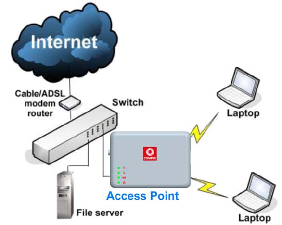
Access Point Mode
The Access Point Mode is the default mode of the access point and
enables the bridging of wireless clients to access the wired network
infrastructure and also enables their communication with each other.
In this example the wireless users are able to access the file server
connected to the switch, through the access point in Access Point
Mode.
Page 5
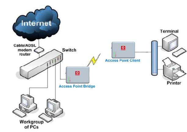
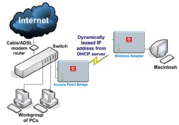
Access Point Client Mode
In Access Point Client Mode the device acts as a wireless client.
When connected to an access point, it creates a network link between
the Ethernet network connected at this client device, and the wireless
Ethernet network connected at the access point.
In this mode it can only connect with another access point. Other
wireless clients cannot connect to it directly unless they are also
connected to the same access point – allowing them to communicate
with all devices connected to the Ethernet port of the access point.
In this example the workgroup PCs can access the printer connected
to the access point in Access Point Client Mode.
Optional additional feature:
Point-to-Point connection in this operation mode is also supported if
you specifically wish to connect with an access point only.
Please refer to the Point-to-Point setup section.
Page 6
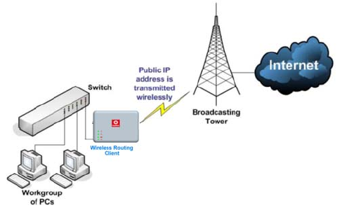
Wireless Routing Client Mode
In Wireless Routing Client Mode the Ethernet port of the access point
may be used to connect with other devices on the network while
Internet access would be provided through wireless communication
with a wireless ISP.
Page 7
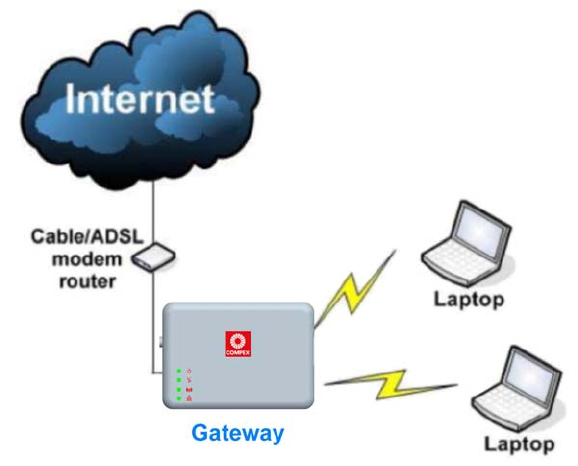
Gateway Mode
In Gateway Mode, the access point supports several types of
broadband connections in a wireless network after you have identified
the type of broadband Internet access you are subscribed to.

Page 8
Broadband Internet Access Type:
Static IP Address
Use Static IP Address if you have subscribed to a fixed IP address or to a
range of fixed IP addresses from your ISP.
Dynamic IP Address
With Dynamic IP Address the access point requests for, and is
automatically assigned an IP address by your ISP, for instance:
• Singapore Cable Vision
• @HOME Cable Services
PPP over Ethernet (PPPoE)
Use PPPoE if you are using ADSL services in a country utilizing standard
PPPoE authentication, for instance:
• Germany with T-1 Connection
• Singapore with SingNet Broadband or Pacific Internet
Broadband
PPTP
Use PPTP if you are using ADSL services in a country utilizing PPTP
connection and authentication.
Page 9
Wireless Adapter Mode
In Wireless Adapter Mode, the access point can communicate
wirelessly with another access point to perform transparent bridging
between 2 networks, like in the Access Point Client Mode. In this mode,
however, the wireless adapter connects to a single workstation only.
No client software or drivers are required to use this mode.
Optional additional feature:
Point-to-Point connection in this operation mode is also supported if
you specifically wish to connect with an access point only.
Please refer to the Point-to-Point setup section.
Page 10
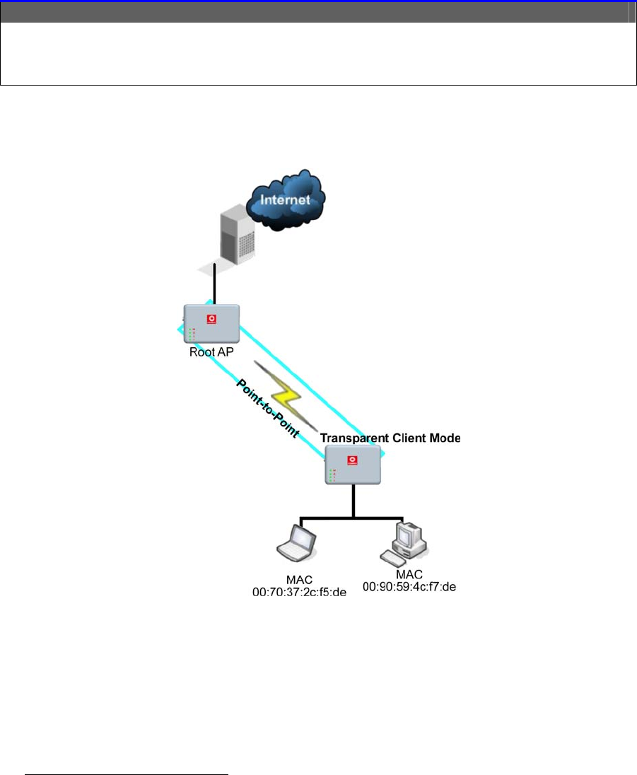
Transparent Client Mode
In Transparent Client Mode, the access point provides connection with
an access point* acting as the RootAP. This operation is designed for
the implementation of Point-to-Point and Point-to-Multipoint
connections.
Point-to-Point Point-to-MultiPoint
An access point acts as Root AP and 1
other access point acts as Transparent
Client.
An access point acts as Root AP
and several other access point
acts as Transparent Clients.
This mode is generally used for outdoor connections over long
distances, or for indoor connections between local networks.
• Current Compex model that provide RootAP support are: WP54x series; WPP54x series; WP18; and NP18A.
For newer models, please contact your Compex supplier or visit the Compex web site.
Page 11
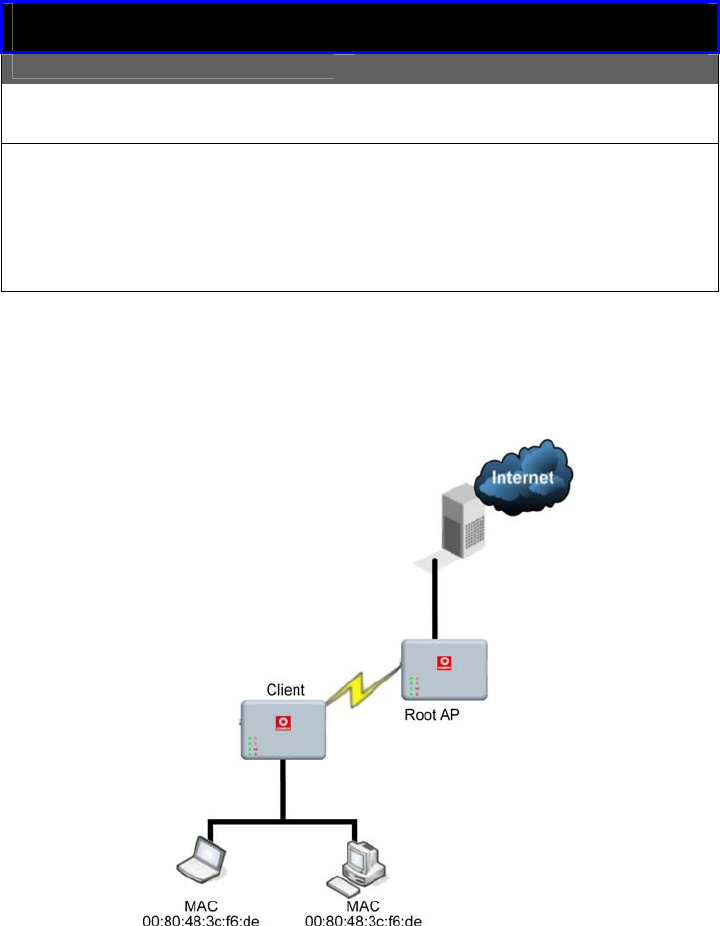
Difference Between other client modes and Transparent
Client Mode
Other client modes Transparent Client Mode
Connectivity with any
standard APs. Connectivity with RootAP-
supported APs.
All devices connected to
the Ethernet port use a
common MAC address for
communications with the
AP.
Devices connected to the
Ethernet port flow through
freely and transparently
without the MAC address
restriction.
The Transparent Client Mode is more transparent, making it more
suitable for linking 2 networks together in a point-to-point, or point-to-
multipoint network connection.
Page 12
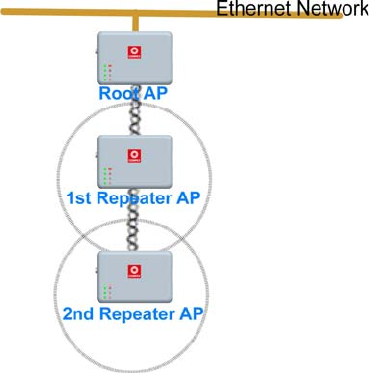
Repeater Mode
The access point comes with a built-in Repeater Mode to extend the
range, and substantially enhance the performance of the wireless
network by allowing communications over much greater distances.
In Repeater Mode, the access point acts as a relay for network signals
on the network by regenerating the signals it receives, and
retransmitting them to extend the range of the existing network
infrastructure.
Detailed information on the Repeater Mode is available in the
Repeater Setup section.
Page 13
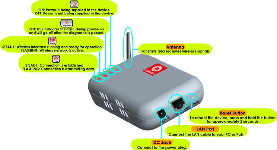
Panel Views and Description

Page 14
Install the Hardware
Setup Requirements
• CAT5/5e Networking Cable.
• At least 1 computer installed with a web browser and a wired or
wireless network interface adapter.
• All network nodes installed with TCP/IP and properly configured
IP address parameters.
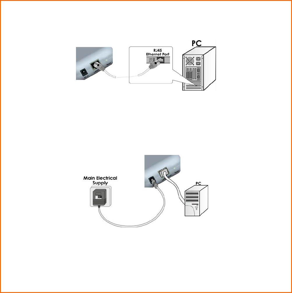
Using power adapter to supply power to
the unit
S
St
te
ep
p
1
1:
:
Connect the external antenna to the SMA connector of the access point.
Page 15
S
St
te
ep
p
2
2:
:
Insert one end of the Ethernet cable to the Ethernet port on your access point, and
the other end of the cable to your PC’s Ethernet network adapter.
S
St
te
ep
p
3
3:
:
Attach the power adapter to the main electrical supply, and connect the power
plug into the socket of the access point.
S
St
te
ep
p
4
4:
:
Turn ON the power supply and power ON your PC. Notice that the LEDs: Power and
Port 1 or 2 (depending on which port you have connected the RJ45 Ethernet cable
to) have lighted up. This indicates that connection has been established
successfully between your access point and your PC.
Page 16
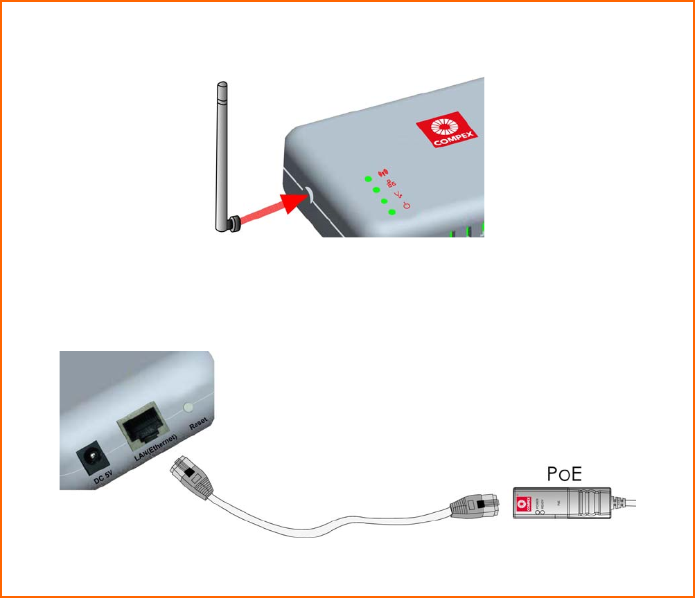
Using PoE to supply power to the unit
PoE is fully compatible with your access point. This accessory supplies
operational power to the wireless AP via the Ethernet cable
connection.
Users who wish to use it to supply power to the access point may follow
the installation procedures as shown below:
S
St
te
ep
p
1
1:
:
Connect the external antenna to the SMA connector of the access point.
S
St
te
ep
p
2
2:
:
Use an RJ45 Ethernet cable to connect one end of the cable to the Ethernet socket
of PoE and the other end to one of the Ethernet ports of the access point.
Page 17
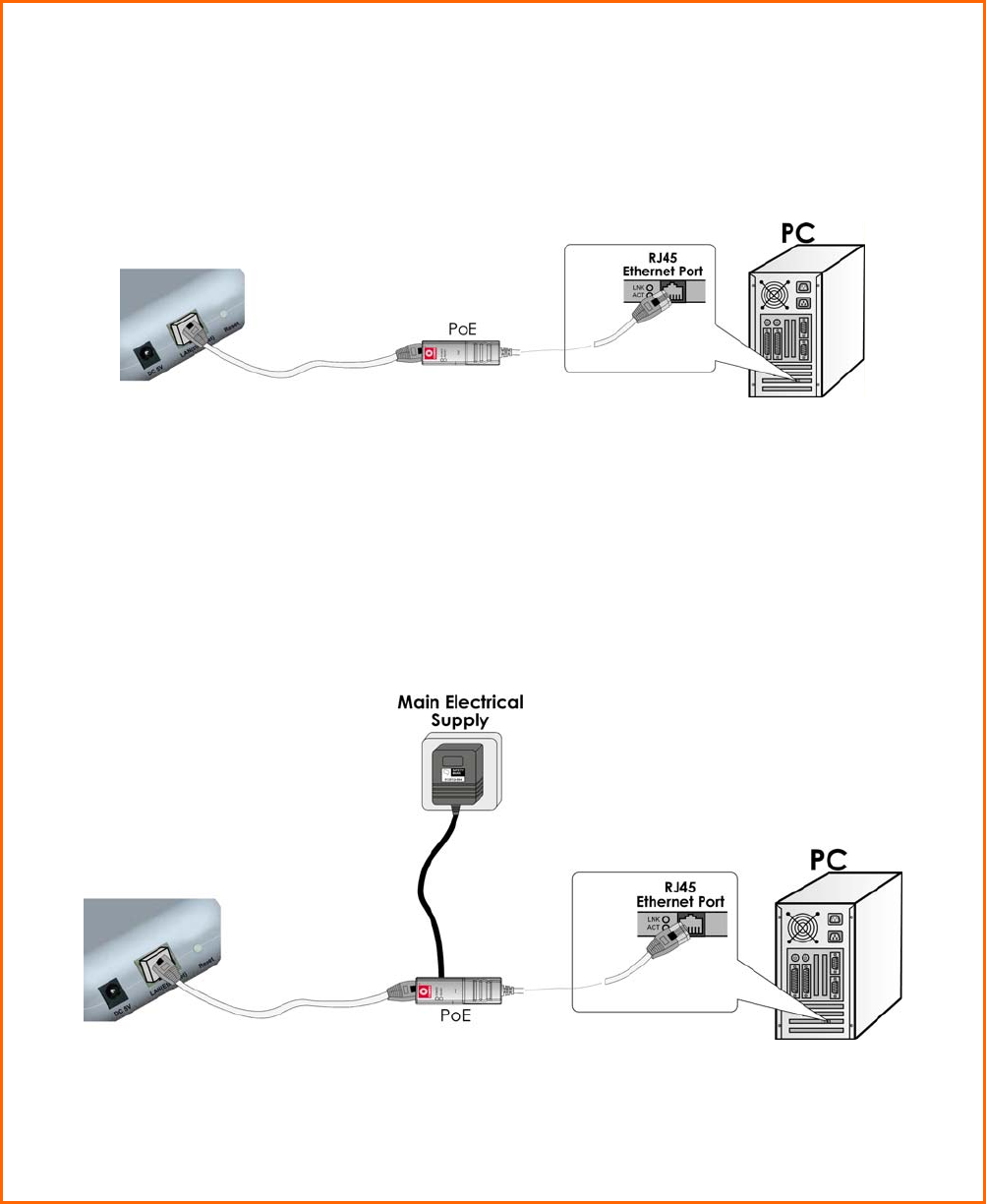
S
St
te
ep
p
3
3:
:
Next, connect the RJ45 Ethernet cable attached to PoE to your PC’s Ethernet
network adapter.
Once you have finished configuring your access point, you can connect the PoE
RJ45 Ethernet cable to your network device, such as to a switch or hub.
S
St
te
ep
p
4
4:
:
Connect the power adapter supplied with PoE to the main electrical supply and the
power plug into the socket of PoE.
Note:
The voltage and current supplied to the access point’s power adapter and PoE
power adapter are different. Do not interchange the power adapters.
S
St
te
ep
p
5
5:
:
Now, turn on your power supply. Notice that the LEDs have lighted up. This indicates
that the access point is receiving power through PoE and that connection between
the access point and your PC has been established.
Page 18
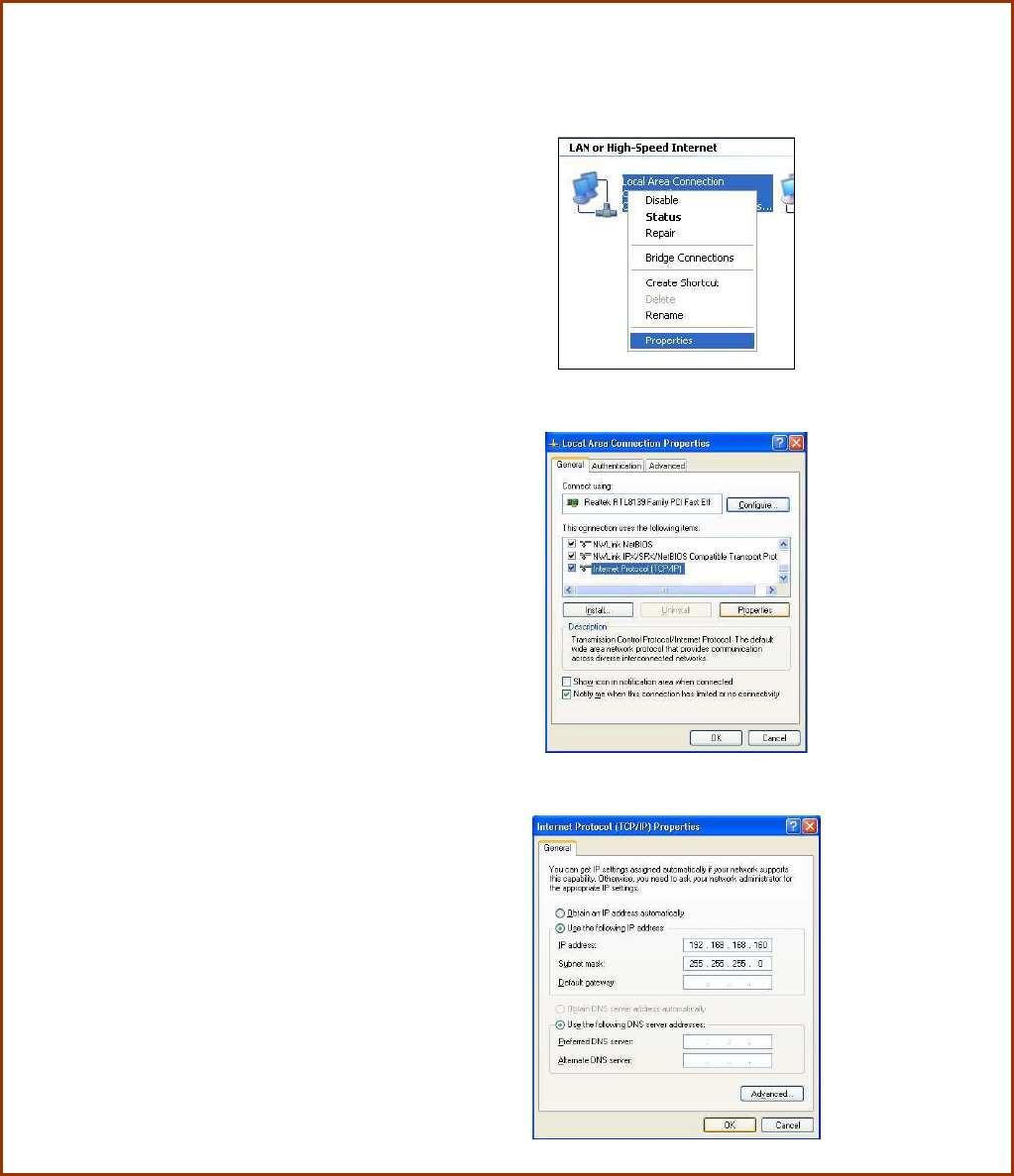
Setup for Windows XP/2000
S
St
te
ep
p
1
1:
:
Go to your desktop, right-click on the My Network Places icon and select Properties.
S
St
te
ep
p
2
2:
:
Right-click the network
adapter icon and select
Properties.
S
St
te
ep
p
3
3:
:
Highlight Internet Protocol
(TCP/IP) and click on the
Properties button.
S
St
te
ep
p
4
4:
:
Select the Use the following
IP address radio button.
Set the IP address to
192.168.168.X and subnet
mask to 255.255.255.0,
where X can be any
number from 2 to 254.
Page 19
S
St
te
ep
p
5
5:
:
Click on the OK button to close all windows.
S
St
te
ep
p
6
6:
:
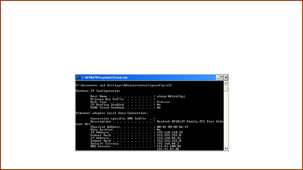
To verify that the IP address has been correctly assigned to your PC, go to the Start
menu, Accessories, select Command Prompt, and type the command: ipconfig/all
Your PC is now ready to communicate with your access point.
Page 20
Access the Web Interface
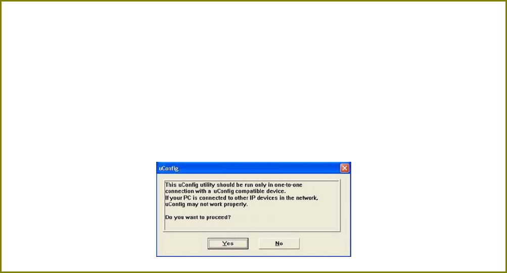
Access with uConfig
The UConfig utility provides direct access to the web interface.
S
St
te
ep
p
1
1:
:
Insert the Product CD into your CD-ROM drive, the CD will autorun.
S
St
te
ep
p
2
2:
:
From the U
Ut
ti
il
li
it
ti
ie
es
s section, select to install the u
uC
Co
on
nf
fi
ig
g utility to your hard disk.
S
St
te
ep
p
3
3:
:
After installation double-click on the u
uC
Co
on
nf
fi
ig
g icon and click on the Y
Ye
es
s button.
Page 21
S
St
te
ep
p
6
6:
:
Select the access point from the products list and click on the O
Op
pe
en
n
W
We
eb
b button. To
retrieve and display the latest device(s) in the list, click on the R
Re
ef
fr
re
es
sh
h button.
S
St
te
ep
p
7
7:
:
Do not exit the uConfig program while accessing the web-based interface as this
will disconnect you from the device. Click on the O
OK
K button.
Page 22
S
St
te
ep
p
8
8:
:
At the login page, press the L
LO
OG
GI
IN
N!
! button to enter the configuration page. The
default password is: password
S
St
te
ep
p
9
9:
:
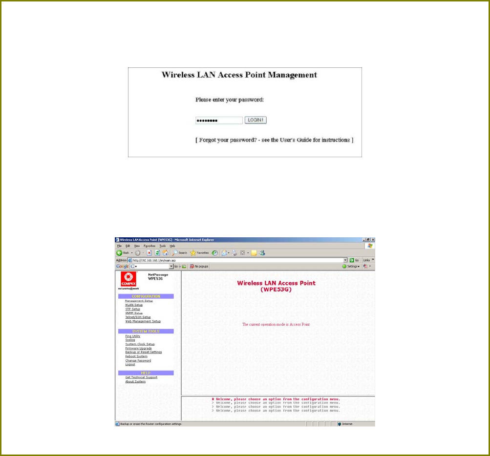
You will then reach the home page of the access point web-based interface.
Page 23
Manual access with Internet Explorer
S
St
te
ep
p
1
1:
:
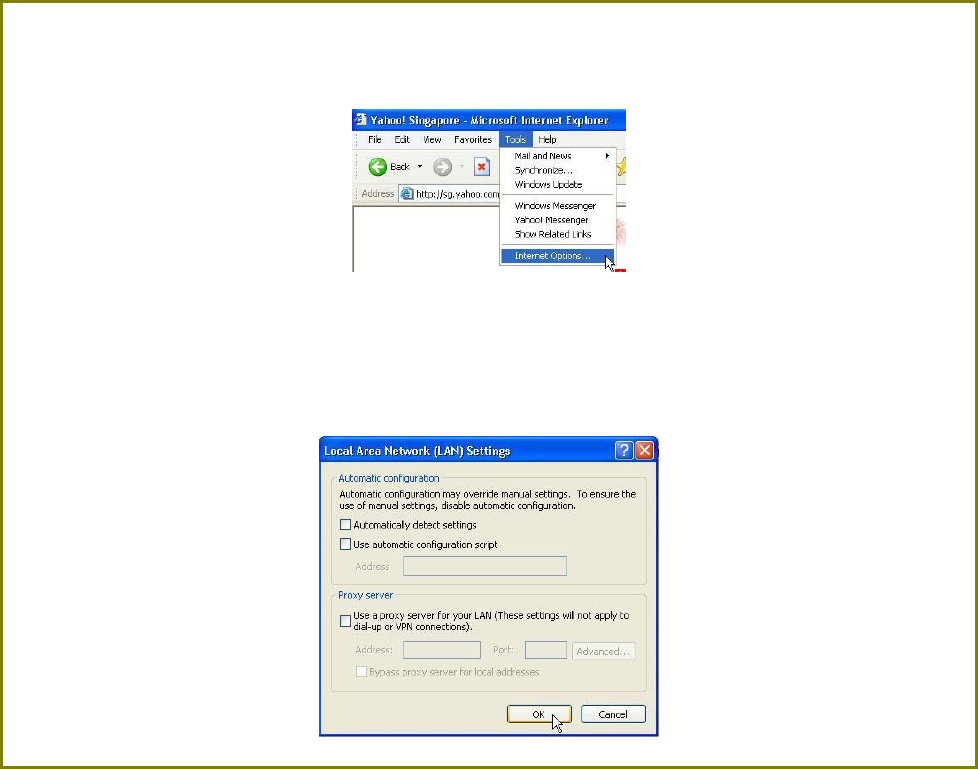
Launch your Web browser and under the T
To
oo
ol
ls
s tab, select I
In
nt
te
er
rn
ne
et
t
O
Op
pt
ti
io
on
ns
s.
S
St
te
ep
p
2
2:
:
Open the C
Co
on
nn
ne
ec
ct
ti
io
on
ns
s tab and in the L
LA
AN
N
S
Se
et
tt
ti
in
ng
gs
s section disable all the option
boxes. Click on the O
OK
K button to update the changes.
Page 24
S
St
te
ep
p
3
3:
:
At the A
Ad
dd
dr
re
es
ss
s bar type in http://192.168.168.1 and press E
En
nt
te
er
r on your keyboard.
S
St
te
ep
p
4
4:
:
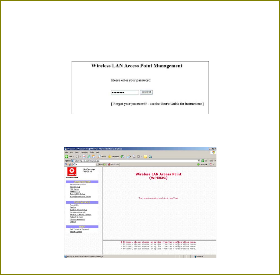
At the login page, click on the L
LO
OG
GI
IN
N!
! Button.
You will then reach the home page of the access point web interface.

Page 25
Perform Basic Configuration
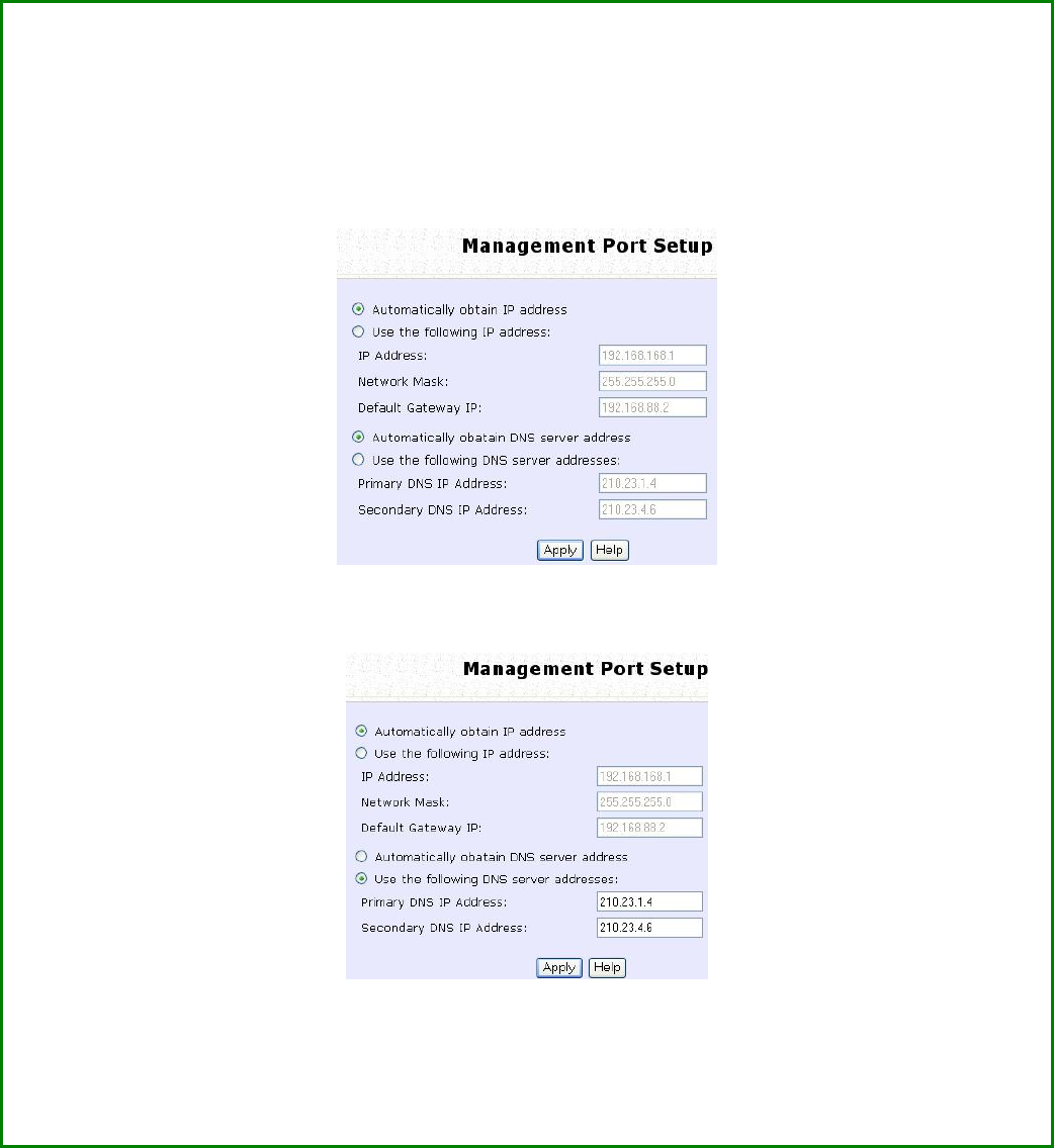
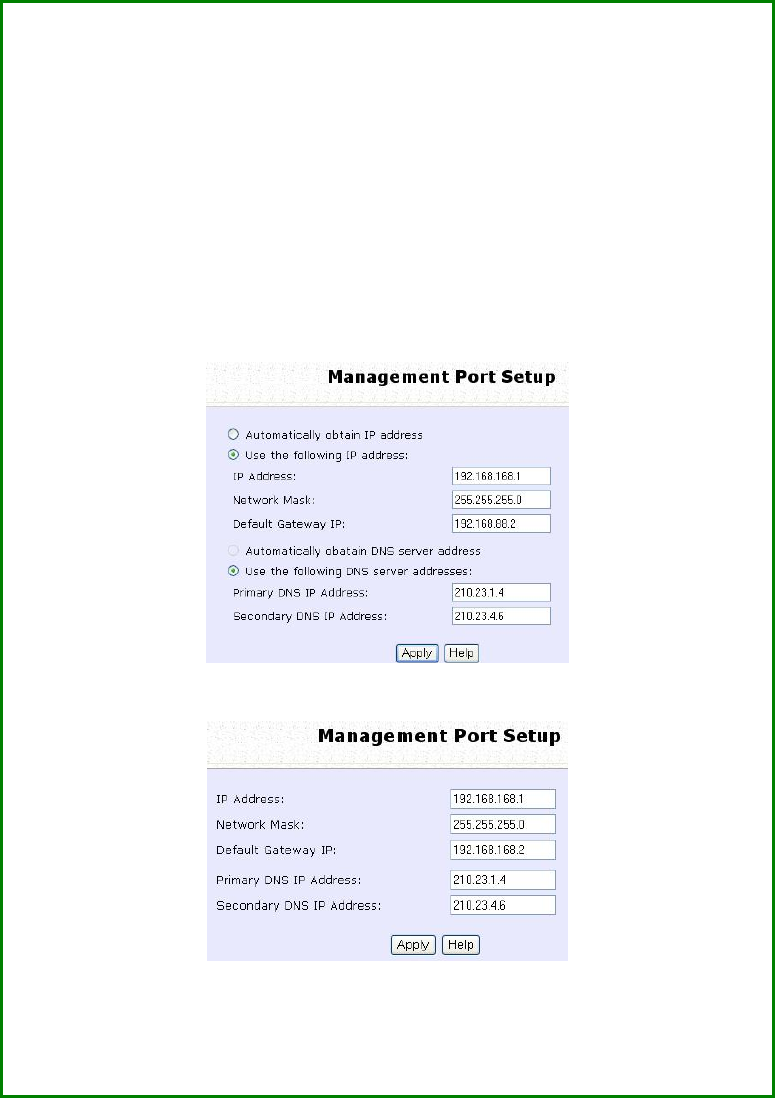
Setup Management Port
At the Management Port Setup page, you may:
• Automatically obtain IP address from DHCP server.
The default IP 192.168.168.1 is used until a new IP is obtained.
Access Point Clients also allows PCs connected to the Ethernet
port to obtain IP from the DHCP server at the access point end
network.
• Manually define IP address
Follow these steps to automatically obtain the IP address from DHCP
server.
S
St
te
ep
p
1
1:
:
Click on T
TC
CP
P/
/I
IP
P
S
Se
et
tt
ti
in
ng
gs
s from M
Ma
an
na
ag
ge
em
me
en
nt
t S
Se
et
tu
up
p from the C
CO
ON
NF
FI
IG
GU
UR
RA
AT
TI
IO
ON
N menu.
S
St
te
ep
p
2
2:
:
Select to A
Au
ut
to
om
ma
at
ti
ic
ca
al
ll
ly
y
o
ob
bt
ta
ai
in
n
I
IP
P
a
ad
dd
dr
re
es
ss
s.
Page 26
S
St
te
ep
p
3
3:
:
Select to either A
Au
ut
to
om
ma
at
ti
ic
ca
al
ll
ly
y
o
ob
bt
ta
ai
in
n
D
DN
NS
S
s
se
er
rv
ve
er
r
a
ad
dd
dr
re
es
ss
s or U
Us
se
e
t
th
he
e
f
fo
ol
ll
lo
ow
wi
in
ng
g
D
DN
NS
S
s
se
er
rv
ve
er
r
a
ad
dd
dr
re
es
ss
se
es
s and enter the parameters, if any.
In the M
Ma
an
na
ag
ge
em
me
en
nt
t
P
Po
or
rt
t
S
Se
et
tu
up
p page, refer to the table below to replace the default
settings of Access point with appropriate values to suit the needs of your network.
If you choose to Automatically obtain DNS server address.
If you choose to Use the following DNS server addresses.
S
St
te
ep
p
4
4:
:
Click on the A
Ap
pp
pl
ly
y
button to save your new parameters.

Page 27
This table describes the parameters that can be modified in the
Management Port Setup page if you select to Use the following DNS
server addresses.
Parameters Description
Primary DNS
IP Address Your ISP usually provides the IP address of
the DNS server.
Secondary
DNS IP
Address
This optional field is reserved for the IP
address of a secondary DNS server.
Page 28
Follow these steps to manually define the IP address.
S
St
te
ep
p
1
1:
:
Click on T
TC
CP
P/
/I
IP
P
S
Se
et
tt
ti
in
ng
gs
s from M
Ma
an
na
ag
ge
em
me
en
nt
t S
Se
et
tu
up
p from the
C
CO
ON
NF
FI
IG
GU
UR
RA
AT
TI
IO
ON
N menu.
S
St
te
ep
p
2
2:
:
Select to U
Us
se
e
t
th
he
e
f
fo
ol
ll
lo
ow
wi
in
ng
g
I
IP
P
a
ad
dd
dr
re
es
ss
s.
In the M
Ma
an
na
ag
ge
em
me
en
nt
t
P
Po
or
rt
t
S
Se
et
tu
up
p page, refer to the table below to
replace the default settings of Access point with appropriate
values to suit the needs of your network.
The parameters are the same in routing mode.
S
St
te
ep
p
3
3:
:
Click on the A
Ap
pp
pl
ly
y
button to save your new parameters.

Page 29
This table describes the parameters that can be modified in the
Management Port Setup page.
Parameters Description
IP Address When the DHCP server of the access point is enabled (unless
you set a different DHCP Gateway IP Address), this LAN IP
Address would be allocated as the Default Gateway of the
DHCP client.
The IP address of your Access point is set by default to
192.168.168.1.
Network
Mask The Network Mask serves to identify the subnet in which your
Access point resides. The default network mask is
255.255.255.0.
Default
Gateway IP (Optional) As a bridge Access Point, the access point does
not usually communicate with devices on other IP subnets.
However, the Default Gateway a PC allows the access point
to communicate with devices on different subnets. For
instance, if you want to access the access point from the
Internet or from a router on the LAN, enter the router IP
address in the Default Gateway IP field.
The Default Gateway IP address of your access point is set to
nil by default.
Primary DNS
IP Address Your ISP usually provides the IP address of the DNS server.
Secondary
DNS IP
Address
This optional field is reserved for the IP address of a
secondary DNS server.
Page 30
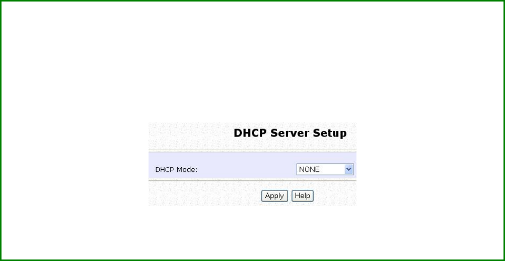
Setup DHCP Server
There are 3 DHCP Modes:
• NONE
By default, DHCP Mode is set to NONE. Leave the selection at this
mode if you do not wish to use DHCP.
• DHCP Server
Select this mode to setup a DHCP server.
• DHCP Relay
Select this mode to setup a DHCP relay.
By default, DHCP broadcast messages do not cross router
interfaces.
DHCP Relay supports DHCP Clients and DHCP Servers on different
networks by configuring the router to pass selective DHCP
messages.
Follow these steps if you do not wish to use DHCP.
S
St
te
ep
p
1
1:
:
Click on A
Ad
dv
va
an
nc
ce
ed
d
S
Se
et
tt
ti
in
ng
gs
s from M
Ma
an
na
ag
ge
em
me
en
nt
t S
Se
et
tu
up
p from the C
CO
ON
NF
FI
IG
GU
UR
RA
AT
TI
IO
ON
N
menu.
S
St
te
ep
p
2
2:
:
Set D
DH
HC
CP
P
M
Mo
od
de
e to N
NO
ON
NE
E.
S
St
te
ep
p
3
3:
:
Click on the A
Ap
pp
pl
ly
y
button.
Page 31
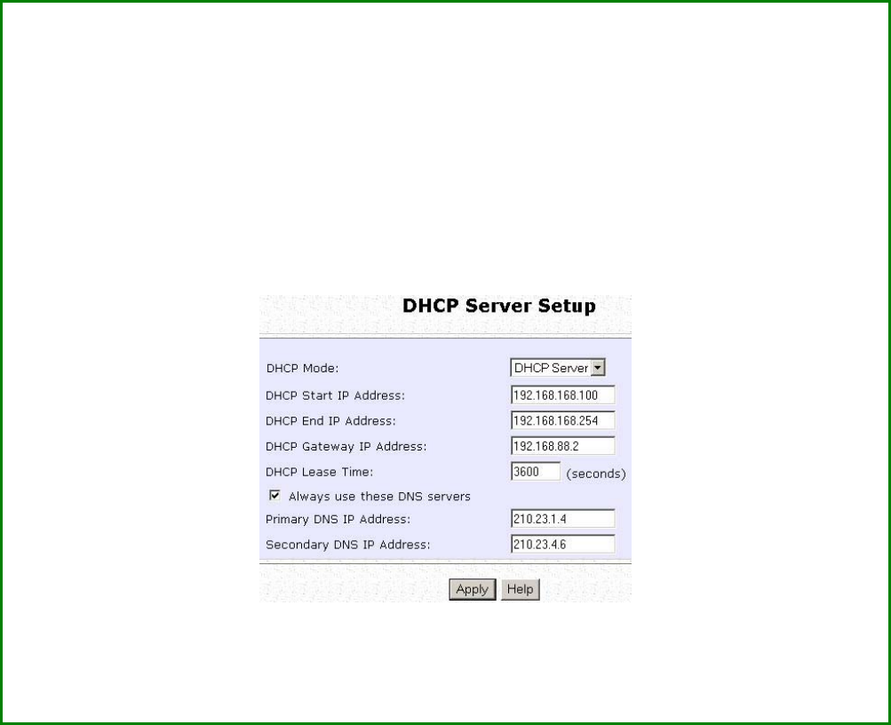
The following will guide you to setup the DHCP Server.
S
St
te
ep
p
1
1:
:
Click on A
Ad
dv
va
an
nc
ce
ed
d
S
Se
et
tt
ti
in
ng
gs
s from M
Ma
an
na
ag
ge
em
me
en
nt
t S
Se
et
tu
up
p from the C
CO
ON
NF
FI
IG
GU
UR
RA
AT
TI
IO
ON
N
menu.
S
St
te
ep
p
2
2:
:
Set D
DH
HC
CP
P
M
Mo
od
de
e to D
DH
HC
CP
P
S
Se
er
rv
ve
er
r.
In D
DH
HC
CP
P
S
Se
er
rv
ve
er
r
S
Se
et
tu
up
p, refer to the table below to set the appropriate values to suit
the needs of your network.
S
St
te
ep
p
3
3:
:
Click on the A
Ap
pp
pl
ly
y
button.

Page 32
This table describes the parameters that can be modified in DHCP
Server Setup.
Parameters Description
The fields DHCP Start IP Address and DHCP End IP Address fields allow you to
define the range of IP addresses from which the DHCP Server can assign an IP
address to the LAN.
DHCP Start IP Address
This is the first IP address that the DHCP server will
assign and should belong to the same subnet as
the access point. For example if the access point
IP address is 192.168.168.1 and the network mask is
192.168.168.1 and 255.255.255.0, the DHCP Start IP
Address should be 192.168.168.X, where X can be
any number from 2 to 254. It is pre-set to
192.168.168.100.
DHCP End IP Address
This is the last IP address that the DHCP server can
assign and should also belong to the same subnet
as your access point. For example if the access
point IP address is 192.168.168.1 and the network
mask is 192.168.168.1 and 255.255.255.0, the DHCP
End IP Address should be 192.168.168.X, where X
can be any number from 2 to 254. It is pre-set as
192.168.168.254.

Page 33
DHCP Gateway IP
Address
Though the DHCP server usually also acts as the
Default Gateway of the DHCP client, the access
point allows you to define a different Gateway IP
Address which will be allocated as the Default
Gateway IP of the DHCP client. The DHCP client
will thus receive its dynamic IP address from the
access point but will access to the Internet or the
other LAN through the Default Gateway defined
by the DHCP Gateway IP Address.
For instance if the access point in Access Point
Client mode connects to an Internet gateway X, a
PC wired to the access point will be unable to
obtain a dynamic IP address directly from X. But if
you enable the DHCP server of the access point
and set the IP address of X as the DHCP Gateway
IP Address, the PC will obtain its IP address from
the access point and access the Internet through
X.
DHCP Lease Time
This is the length of time that the client may use
the assigned address before having to check with
the DHCP server to see if the Address is still valid.
Always use these DNS
servers
Select this option to always use the DNS servers
specified.
Primary DNS IP Address
Your ISP usually provides the IP address of the DNS
server.
Secondary DNS IP Address
This optional setting is the IP address of a
secondary DNS server.
Page 34
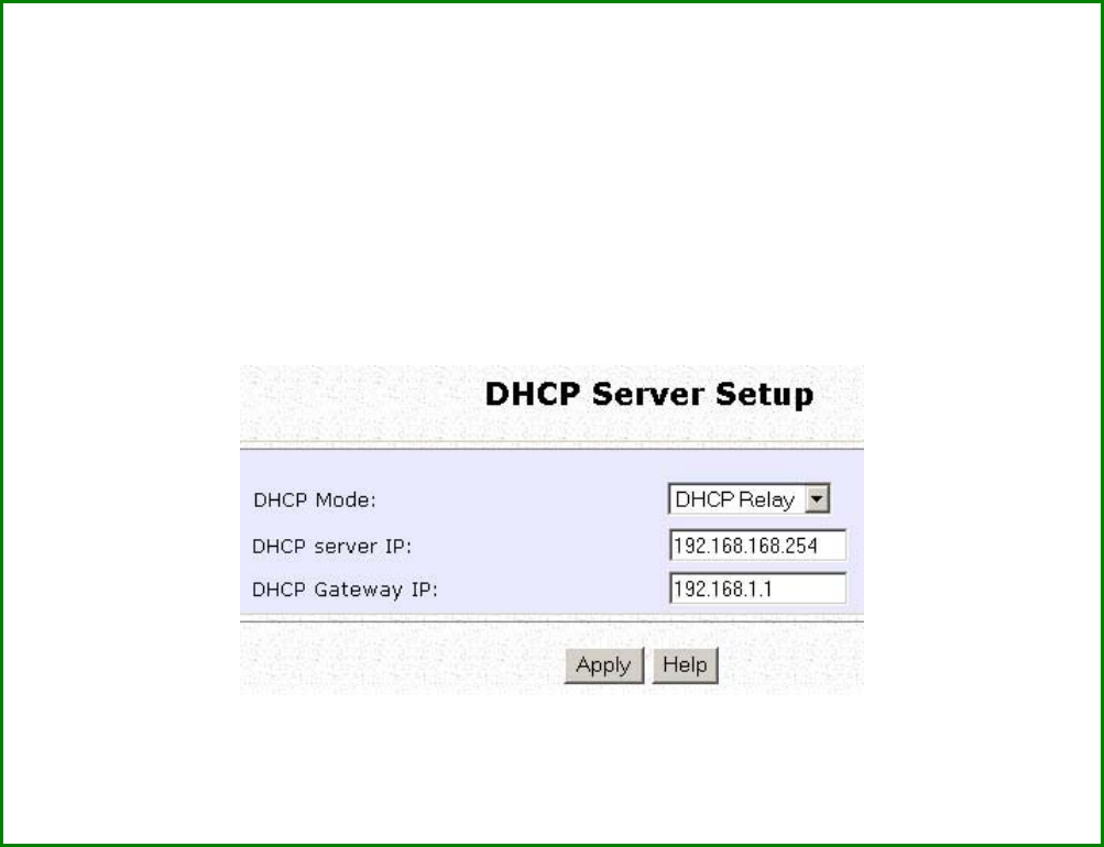
The following will guide you to setup the DHCP Relay.
(Available in Client and Wireless Routing Client modes)
S
St
te
ep
p
1
1:
:
Click on A
Ad
dv
va
an
nc
ce
ed
d
S
Se
et
tt
ti
in
ng
gs
s from M
Ma
an
na
ag
ge
em
me
en
nt
t S
Se
et
tu
up
p from the C
CO
ON
NF
FI
IG
GU
UR
RA
AT
TI
IO
ON
N
menu.
S
St
te
ep
p
2
2:
:
Set D
DH
HC
CP
P
M
Mo
od
de
e to D
DH
HC
CP
P
R
Re
el
la
ay
y.
In D
DH
HC
CP
P
S
Se
er
rv
ve
er
r
S
Se
et
tu
up
p, refer to the table below to set the appropriate values to suit
the needs of your network.
S
St
te
ep
p
3
3:
:
Click on the A
Ap
pp
pl
ly
y
button.

Page 35
This table describes the parameters that can be modified in DHCP
Server Setup.
Parameters Description
DHCP Server IP
This is the IP address of the DHCP server.
DHCP Gateway IP
Though the DHCP server usually also acts as the
Default Gateway of the DHCP client, the access
point allows you to define a different Gateway IP
Address which will be allocated as the Default
Gateway IP of the DHCP client. The DHCP client
will thus receive its dynamic IP address from the
access point but will access to the Internet or the
other LAN through the Default Gateway defined
by the DHCP Gateway IP Address.
For instance if the access point in Access Point
Client mode connects to an Internet gateway X,
a PC wired to the access point will be unable to
obtain a dynamic IP address directly from X. But
if you enable the DHCP server of the access
point and set the IP address of X as the DHCP
Gateway IP Address, the PC will obtain its IP
address from the access point and access the
Internet through X.
Page 36
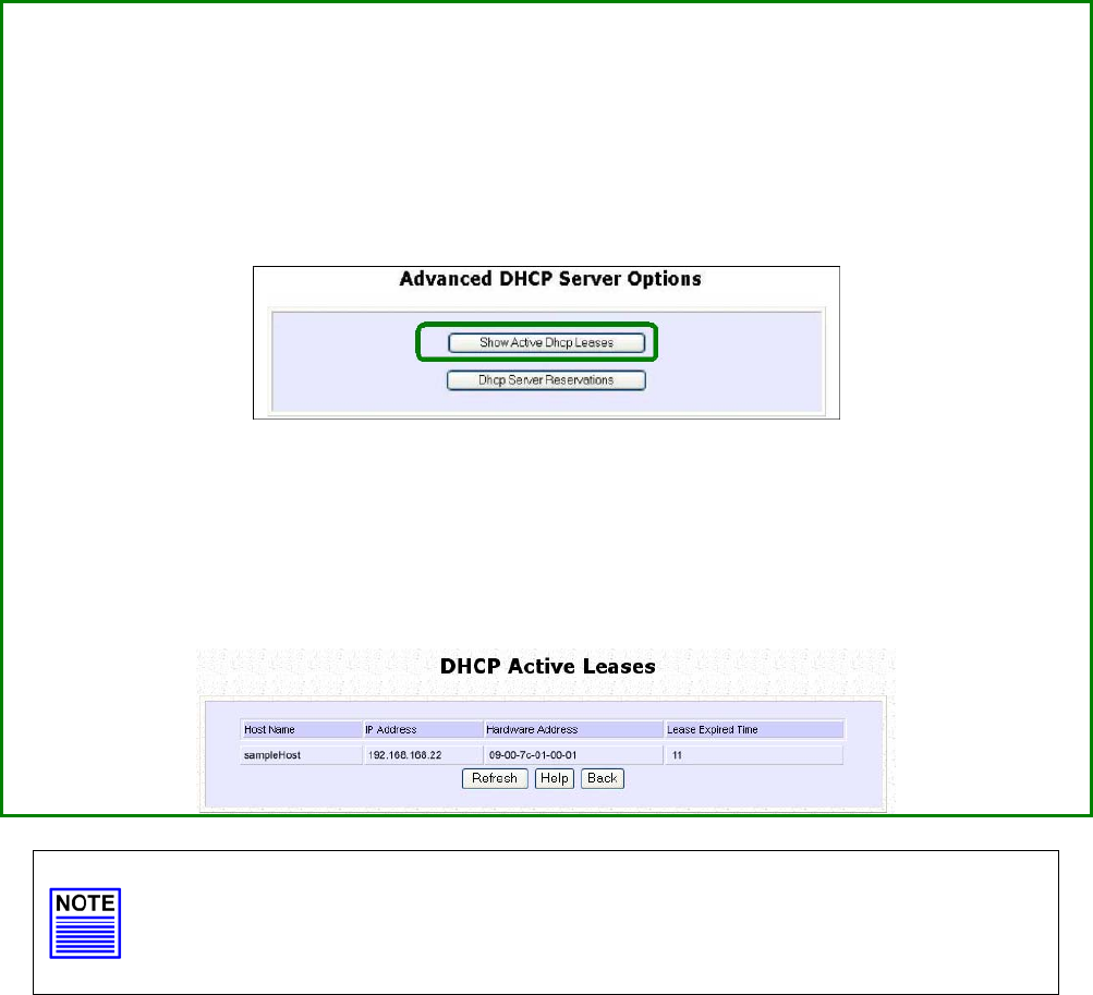
View Active DHCP Leases
S
St
te
ep
p
1
1:
:
Select M
Ma
an
na
ag
ge
em
me
en
nt
t S
Se
et
tu
up
p from the C
CO
ON
NF
FI
IG
GU
UR
RA
AT
TI
IO
ON
N menu.
S
St
te
ep
p
2
2:
:
Go to the A
Ad
dv
va
an
nc
ce
ed
d
D
DH
HC
CP
P
S
Se
er
rv
ve
er
r O
Op
pt
ti
io
on
ns
s section and click on the S
Sh
ho
ow
w
A
Ac
ct
ti
iv
ve
e
D
DH
HC
CP
P
l
le
ea
as
se
es
s button.
The DHCP Active Leases table displays:
• The Host Name of the DHCP client.
• The IP Address allocated to the DHCP client.
• The Hardware (MAC) Address of the DHCP client.
• The Lease Expired Time.
NOTE
Invalid date and time displayed in the Lease Expired Time column
indicates that the clock of the access point has not been set properly.
Page 37
Reserve IP Addresses for Predetermined
DHCP Clients
A reserved IP address is excluded from the pool of free IP addresses the
DHCP server draws on for dynamic IP address allocation.
For instance if you set up a publicly accessible FTP or HTTP server within
your private LAN, while that server requires a fixed IP address you would
still want the DHCP server to dynamically allocate IP addresses to the
rest of the PCs on the LAN.
S
St
te
ep
p
1
1:
:
From the A
Ad
dv
va
an
nc
ce
ed
d
D
DH
HC
CP
P
S
Se
er
rv
ve
er
r Options section click on the D
DH
HC
CP
P
S
Se
er
rv
ve
er
r
R
Re
es
se
er
rv
va
at
ti
io
on
ns
s
button.
S
St
te
ep
p
2
2:
:
Click on the A
Ad
dd
d button.
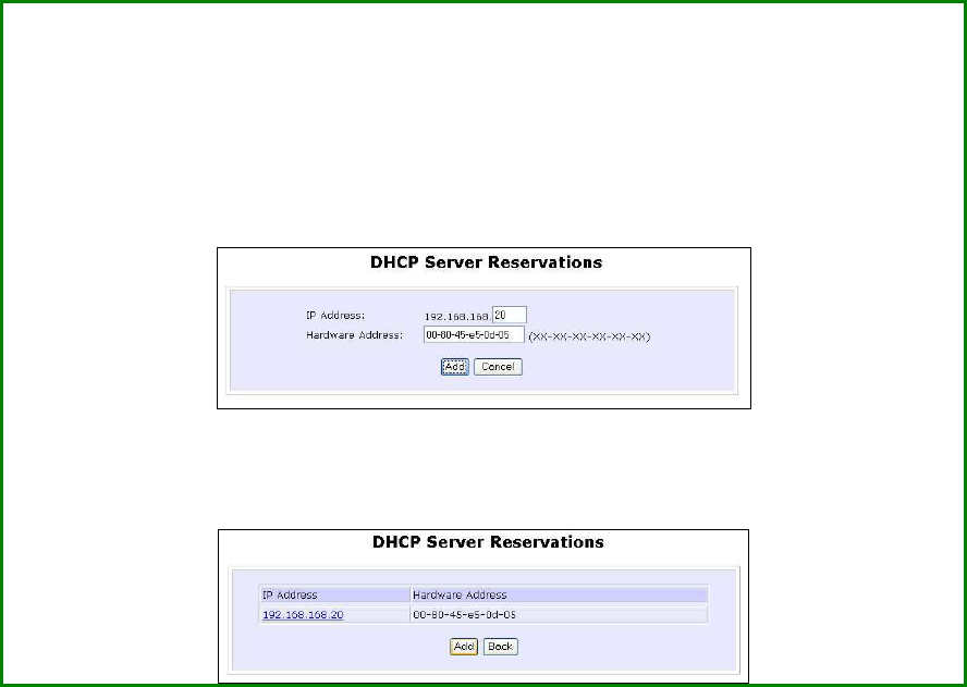
Page 38
S
St
te
ep
p
3
3:
:
Fill in:
The host portion of the IP Address to be reserved.
The Hardware Address, in pairs of two hexadecimal values.
Press the A
Ap
pp
pl
ly
y button to effect your new entry.
The D
DH
HC
CP
P
S
Se
er
rv
ve
er
r
R
Re
es
se
er
rv
va
at
ti
io
on
ns
s page refreshes to display the currently
reserved IP addresses.
Page 39
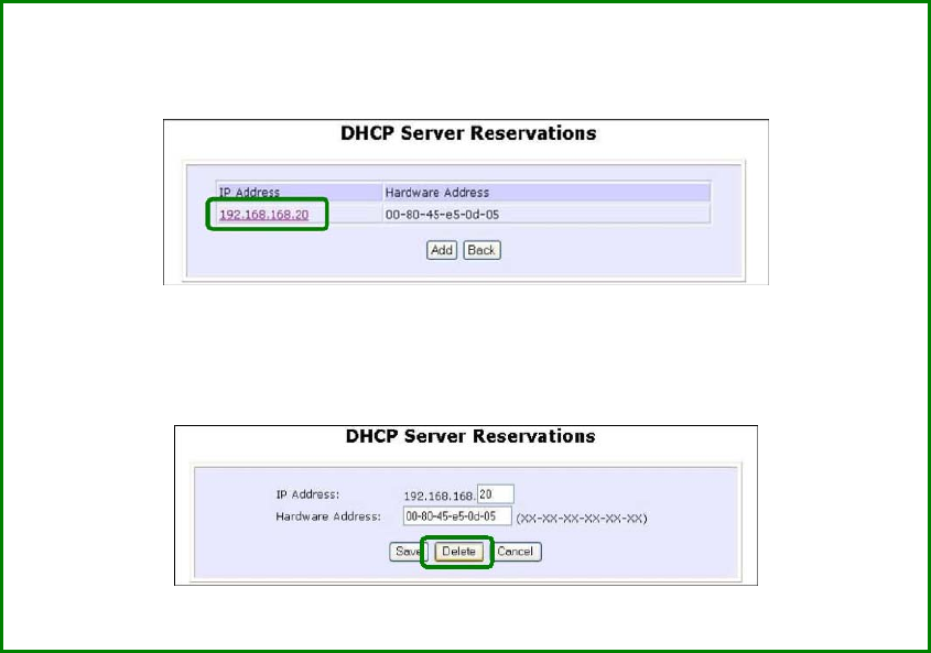
Delete DHCP Server Reservation
S
St
te
ep
p
1
1:
:
Select the reserved IP address to delete.
S
St
te
ep
p
2
2:
:
Click on the D
De
el
le
et
te
e button.
The D
DH
HC
CP
P
S
Se
er
rv
ve
er
r
R
Re
es
se
er
rv
va
at
ti
io
on
ns
s table refreshes to display your changes.
Page 40
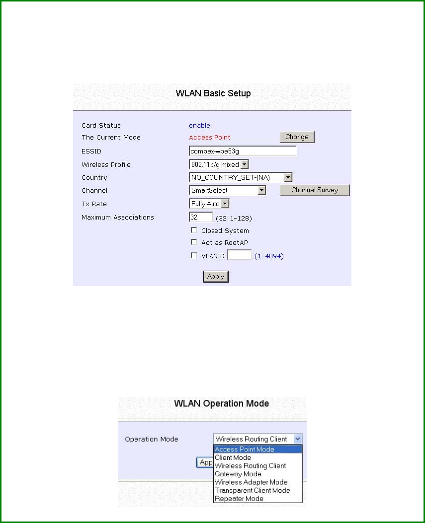
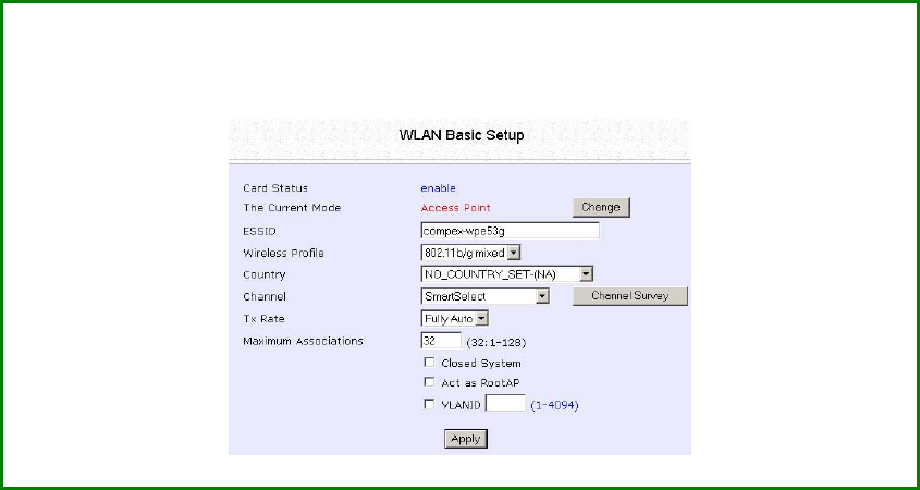
Setup WLAN
Configure the Basic Setup of the Wireless
Mode
S
St
te
ep
p
1
1:
:
Select W
WL
LA
AN
N
S
Se
et
tu
up
p from the C
CO
ON
NF
FI
IG
GU
UR
RA
AT
TI
IO
ON
N menu and you will see
the sub menus expanded under W
WL
LA
AN
N
S
Se
et
tu
up
p, select B
Ba
as
si
ic
c.
The default operating mode of the access point is the Access Point
mode.
S
St
te
ep
p
2
2:
:
(
(O
Op
pt
ti
io
on
na
al
l:
:
C
Ch
ha
an
ng
ge
e
C
Cu
ur
rr
re
en
nt
t
m
mo
od
de
e)
)
To change the current mode of the access point click on C
Ch
ha
an
ng
ge
e,
select the O
Op
pe
er
ra
at
ti
io
on
n
M
Mo
od
de
e, and click on the A
Ap
pp
pl
ly
y button to access
the setup page of the selected mode. You will be prompted to reboot
the access point to effect the mode setting.
Page 41
Step 3:
Enter the parameters in their respective fields, click on the
A
Ap
pp
pl
ly
y button and reboot your device to let your changes
take effect.
Note that the W
WL
LA
AN
N
B
Ba
as
si
ic
c
S
Se
et
tu
up
p pages for the modes are
different.
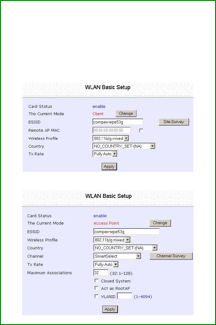
Example: W
WL
LA
AN
N
B
Ba
as
si
ic
c
S
Se
et
tu
up
p page for C
Cl
li
ie
en
nt
t
M
Mo
od
de
e
Example: W
WL
LA
AN
N
B
Ba
as
si
ic
c
S
Se
et
tu
up
p page for A
Ac
cc
ce
es
ss
s
P
Po
oi
in
nt
t

Page 42
WLAN Basic Setup
page Parameters Description
The Current Mode
The default operating mode is the Access Point mode. Operating
modes:
• Access Point Mode
• Client Mode
• Wireless Routing Client
• Gateway Mode
• Wireless Adapter Mode
• Transparent Client Mode
• Repeater Mode
You can toggle the modes by clicking on the C
Ch
ha
an
ng
ge
e button.
ESSID
Enter a preferred name for the wireless network. Your wireless
clients must be configured with the same ESSID.
This case-sensitive entry can consist of a maximum of 32
characters.
Site Survey
A list of wireless devices in the WLAN that are detected by your
access point. Information such as MAC address, channel, SSID,
algorithm and signal strength can be found in the listing.
This feature is supported by the Access Point Client and Wireless
Routing Client modes.

Page 43
Wireless Profile
A selection of network environment types in which to operate the
access point:
•
•
8
80
02
2.
.1
11
1b
b
o
on
nl
ly
y
Supports wireless B clients with data rates of up to 11Mbps in the
frequency range of 2.4GHz.
•
•
8
80
02
2.
.1
11
1b
b/
/g
g
m
mi
ix
xe
ed
d
Supports both wireless B and G clients.
•
•
8
80
02
2.
.1
11
1g
g
o
on
nl
ly
y
Supports wireless-G clients that offer transmission rates of up to
54Mbps in the 2.4GHz frequency band.
•
•
s
su
up
pe
er
rG
G
Supports wireless superG clients that offer transmission rates of up to
108Mbps in the 5GHz frequency band.
Country
Choose the Country where you are located.
Channel
This option allows you to select a frequency channel for the wireless
communication and is only available in the Access Point, Point to
Point and Point to Multiple Point modes.
Select SmartSelect to automatically scan and recommend the
best channel that the access point can utilize.
Tx Rate
Allows you to choose the rate of data transmission ranging from
1Mbps to Fully Auto.
Closed System
The access point will not broadcast its WLAN name (ESSID) when
Closed system is enabled. By default Closed system is disabled.

Page 44
Act as RootAP
The access point will connect with 1, or multiple clients to create a
point-to-point and point-to-multi-point connection network with 2
or more access points.
This connection mode is fully compliant with 802.1h standards.
VLAN ID
This is the number that identifies the different virtual network
segments to which the network devices are grouped.
This can be any number from 1 to 4094.
Channel Survey
A list of channels that are detected by your access point in the
WLAN. Information such as frequency, channel, MyQuality,
NeighQuality, APCount and Recommendation can be found in the
listing.
The Access Point and Gateway modes support this feature.
Page 45
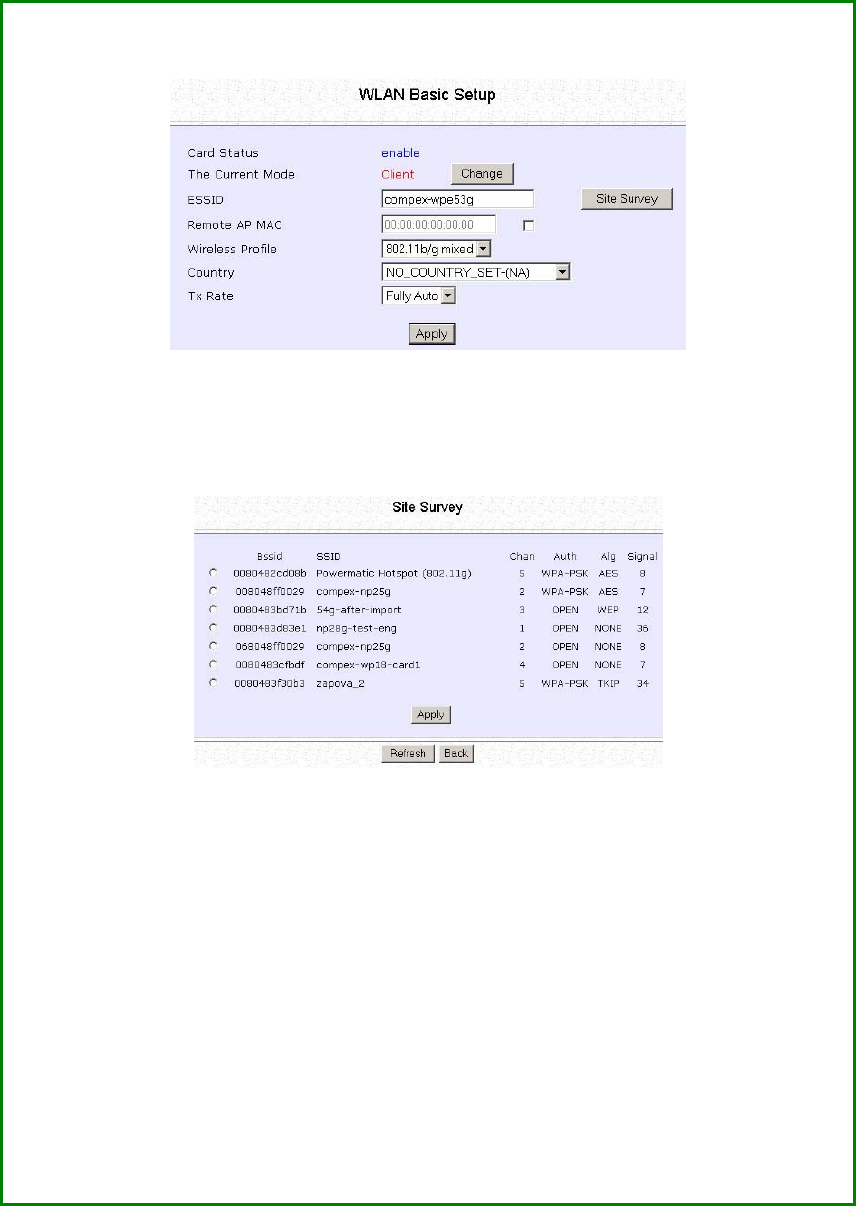
Scan for Site Survey
(Available in Client and Wireless Routing Client modes)
S
St
te
ep
p
1
1:
:
In the M
Mo
od
de
e
S
Se
et
tu
up
p page click on the S
Si
it
te
e
S
Su
ur
rv
ve
ey
y button.
The S
Si
it
te
e
S
Su
ur
rv
ve
ey
y provides a list of the M
MA
AC
C
a
ad
dd
dr
re
es
ss
se
es
s
(
(B
BS
SS
SI
ID
D)
) and S
SS
SI
ID
D of
neighbouring access points detected, the C
Ch
ha
an
n (channels), A
Au
ut
th
h
(Authentication), A
Al
lg
g (Algorithm) used, and the strength of the S
Si
ig
gn
na
al
l
received.
S
St
te
ep
p
2
2:
:
To connect the client to one of the access points detected, select the
radio button corresponding to the access point you want to connect
to.
S
St
te
ep
p
3
3:
:
Click on the A
Ap
pp
pl
ly
y button to effect the change and return to the setup
page.
S
St
te
ep
p
4
4:
:
Click on the R
Re
ef
fr
re
es
sh
h button to update the screen.

Page 46
Read-Only Parameters of
Neighbouring Access Points
Viewable from Site Survey page
Description
Bssid
Wireless MAC address of the access point
in a wireless network infrastructure.
SSID
Network name that uniquely identifies the
network to which the access point is
connected.
Chan
Channel being used for transmission.
Auth
Types of authentication, such as WPA,
WPA-Personal, etc being used by the
access point.
Alg
Types of algorithm, such as WEP, TKIP, etc
being used by the access point.
Signal
Strength of the signal received in
percentage.
NOTE
Site Survey is used to scan and display all access points based on the
current security setting of your access point.
Explanation of the following information supplied by the Site Survey
according to the security setting:
• If the security mode is set to None or WEP, the scan will show all
available access points with no security or WEP security
• If the security mode is set to WPA-Personal, the scan will show all
available access points with all types of security from no security,
WEP security to WPA-Personal security.
Page 47
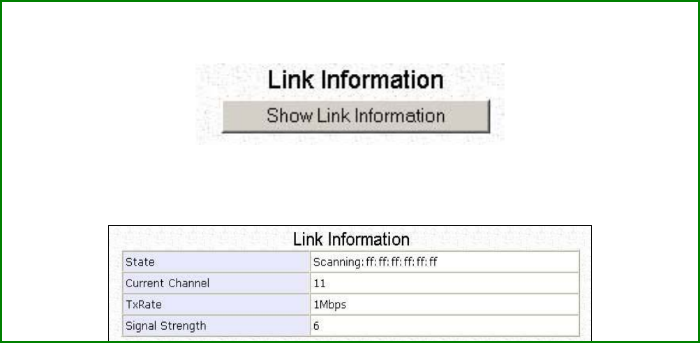
View Link Information
(Available in Client and Wireless Routing Client modes)
To view the connection status when the client is linked to another access point, click
on the S
Sh
ho
ow
w
L
Li
in
nk
k
I
In
nf
fo
or
rm
ma
at
ti
io
on
n button.
The L
Li
in
nk
k
I
In
nf
fo
or
rm
ma
at
ti
io
on
n table displays the following data:

Page 48
Parameters Viewable from
Link Information page Description
State
Displays whether the State is Scanning or Associated,
and MAC address of the access point to which the
client is connected.
Current Channel
Channel presently being used for transmission.
Tx Rate
Rate of data transmission in Mbps.
Signal Strength
Intensity of the signal received, in percentage.
Page 49
Scan for Channel Survey
(Available in Access Point and Gateway modes)
Channel Survey displays a list of all the channels supported by the
access point, shows the relative interference of all the channels, and
recommends the least congested channel.
S
St
te
ep
p
1
1:
:
In the M
Mo
od
de
e
S
Se
et
tu
up
p page, click on the C
Ch
ha
an
nn
ne
el
l
S
Su
ur
rv
ve
ey
y button.
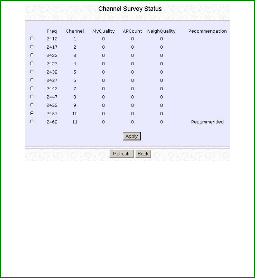
Page 50
S
St
te
ep
p
2
2:
:
To connect the client to one of the channels detected, select the
corresponding radio button.
S
St
te
ep
p
3
3:
:
Click on the A
Ap
pp
pl
ly
y button to effect the change and return to the
setup page.
S
St
te
ep
p
4
4:
:
Click on the R
Re
ef
fr
re
es
sh
h button to update the screen.

Page 51
Read-Only Parameters of All
Channels Viewable from
Channel Survey page
Description
Freq
Frequency of the channel at which your access
point is operating.
Channel
Channel of the access point being used for
transmission depending on its origin of country.
MyQuality
Interference level of the respective channel with this
AP. The lower the value, the less interference. If the
value is zero, there is no interference.
APCount
Total number of access points operating at the
current channel.
NeighQuality
Interference level with those discovered APs at
those respective channels. The lower the value, the
less interference. If the value is zero, there is no
interference.
Recommendation
Best channel for the device to use in its current
environment.
Page 52
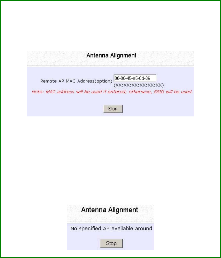
Align the Antenna
Antenna Alignment precisely aligns the antenna over long distances
for higher signal strength to improve the connection between the
access point and another access point.
S
St
te
ep
p
1
1:
:
Select W
WL
LA
AN
N
S
Se
et
tu
up
p from the C
CO
ON
NF
FI
IG
GU
UR
RA
AT
TI
IO
ON
N menu. You will see the
sub-menus expanded under W
WL
LA
AN
N
S
Se
et
tu
up
p. Click on A
An
nt
te
en
nn
na
a
A
Al
li
ig
gn
nm
me
en
nt
t.
The A
An
nt
te
en
nn
na
a
A
Al
li
ig
gn
nm
me
en
nt
t page can act as a diagnostic tool to check
the communication with a remote device. The remote AP MAC
Address is preset to all zeros by default.
S
St
te
ep
p
2
2:
:
If you wish to specify the MAC address of the remote AP, edit the field
next to R
Re
em
mo
ot
te
e
A
AP
P
A
Ad
dd
dr
re
es
ss
s
(
(o
op
pt
ti
io
on
n)
), followed by clicking on the S
St
ta
ar
rt
t
button. A pop-up status screen will display, allowing you to monitor the
signal strength received from the remote access points.
If there is no specified access point with the specified MAC address,
this screen will display. To abort or to key in the MAC address of
another available remote access point, click on the S
St
to
op
p button.

Page 53
NOTE
If no MAC address is entered, the Antenna
Alignment tool will make use of the SSID to align
the antenna. Please ensure that the correct SSID
is entered. If more than one access point share
the same SSID, the access point with the
strongest signal will be shown.
Signal Strength
(RSSI Value) Indicated by DIAG LED Status of DIAG LED
Above 20
Stays turned on.
Between 19 and 17
Flashes 6 times.
Between 17 and 14
Flashes 3 times.
Between 13 and 10
Flashes once.
Below 10
Turns off.
NOTE
Outdoor long distance connection should
preferably have signal strength of a RSSI of 10 and
above.
NOTE
To ensure proper functionality of the device,
select to Stop antenna alignment.
Alternatively, you may also reboot the device.
Page 54
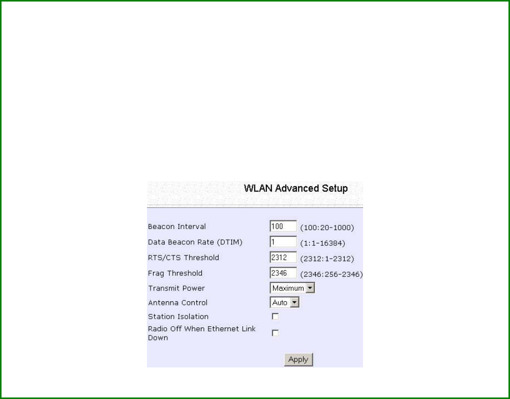
Configure the Advanced Setup of the
Wireless Mode
S
St
te
ep
p
1
1:
:
Select W
WL
LA
AN
N
S
Se
et
tu
up
p from the C
CO
ON
NF
FI
IG
GU
UR
RA
AT
TI
IO
ON
N menu to expand four sub-menus.
From here, select A
Ad
dv
va
an
nc
ce
ed
d.
S
St
te
ep
p
2
2:
:
Enter the parameters in the W
WL
LA
AN
N
A
Ad
dv
va
an
nc
ce
ed
d
S
Se
et
tu
up
p page.
S
St
te
ep
p
3
3:
:
Click on the A
Ap
pp
pl
ly
y button to update the changes.

Page 55
Advanced Setup Parameters Description
Beacon Interval
(Only in Access Point mode)
Amount of time between beacon transmissions. This tells the
client when to receive the beacon. A beacon is a guidance
signal sent by the access point to announce its presence to
other devices in the network.
Data Beacon Rate (DTIM)
(Only in Access Point mode)
How often the beacon contains a delivery traffic indication
message (DTIM). The DTIM identifies which clients have data
waiting to be delivered to them.
If the beacon period is set at the default value of 100, and the
data beacon rate is set at the default value of 1, the access
point will send a beacon containing a DTIM every 100
kilomicrosecond (1 kilomicrosecond equals 1,024 microsecond)
RTS/CTS Threshold Minimum size of a packet in bytes that will trigger the RTS/CTS
mechanism.
This value extends from 1 to 2312 bytes.
Frag Threshold Maximum size that a packet can reach without being
fragmented; represented in bytes.
This value extends from 256 to 2346 bytes, where a value of 0
indicates that all packets should be transmitted using RTS.
Transmit Power
Drop-down list of a range of transmission power.
Radio Off When Ethernet Link
Down
Disables the radio card automatically when the Ethernet link is
down.
NOTE
The values illustrated in the example are suggested values for
their respective parameters.
Page 56
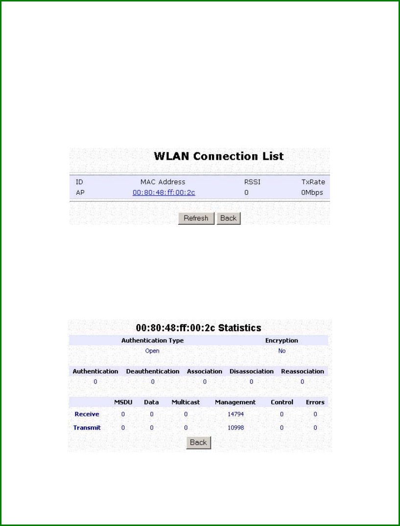
View the Statistics
The Statistics feature reveals information on the wireless device
connected to the WLAN.
S
St
te
ep
p
1
1:
:
Select W
WL
LA
AN
N
S
Se
et
tu
up
p from the C
CO
ON
NF
FI
IG
GU
UR
RA
AT
TI
IO
ON
N menu. The sub-menus
under W
WL
LA
AN
N
S
Se
et
tu
up
p
expand, select S
St
ta
at
ti
is
st
ti
ic
cs
s.
Wireless clients that are connected to the WLAN are shown in the
WLAN Station List.
S
St
te
ep
p
2
2:
:
Click on the R
Re
ef
fr
re
es
sh
h button to get the latest information on the
availability of wireless clients in the wireless network.
S
St
te
ep
p
3
3:
:
To check the details on an individual wireless client, click on the
corresponding MAC Address in the WLAN Station List.
The statistics of the selected wireless client displays.
In C
Cl
li
ie
en
nt
t mode you are not allowed to view the information of other
wireless clients, to do that you need to change to the Access Point
mode.
Page 57
Setup Your WAN
(Available in Wireless Routing Client and Gateway modes)
NOTE:
Any changes to the WAN Setup will only take effect after rebooting.
Setup your WAN to share Internet connection among the clients of the
access point.
Setup your WAN for cable internet whereby WAN IP address is
dynamically assigned by ISP
The access point is pre-configured to support this WAN type.
However, you may verify the WAN settings with the following
steps:
Step 1:
U
Un
nd
de
er
r
C
CO
ON
NF
FI
IG
GU
UR
RA
AT
TI
IO
ON
N
o
on
n
t
th
he
e
c
co
om
mm
ma
an
nd
d
m
me
en
nu
u,
,
s
se
el
le
ec
ct
t
W
WA
AN
N
S
Se
et
tu
up
p.
.
S
St
te
ep
p
2
2:
:
On the W
WA
AN
N
D
Dy
yn
na
am
mi
ic
c
S
Se
et
tu
up
p screen, verify that the W
WA
AN
N
T
Ty
yp
pe
e is
D
Dy
yn
na
am
mi
ic
c
(
(D
DH
HC
CP
P)
). Otherwise, click on the C
Ch
ha
an
ng
ge
e button.
Step 3:
Select D
Dy
yn
na
am
mi
ic
c
I
IP
P
A
Ad
dd
dr
re
es
ss
s and hit the A
Ap
pp
pl
ly
y button.
Reboot to let the settings take effect.
Page 58
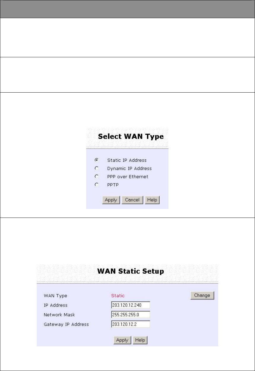
Setup your WAN for cable internet whereby fixed WAN IP
address is assigned by ISP
WAN Setup Parameters Example:
• IP Address: 203.120.12.240
• Network Mask: 255.255.255.0
• Gateway IP Address: 203.120.12.2
Step 1:
U
Un
nd
de
er
r
C
CO
ON
NF
FI
IG
GU
UR
RA
AT
TI
IO
ON
N
o
on
n
t
th
he
e
c
co
om
mm
ma
an
nd
d
m
me
en
nu
u,
,
s
se
el
le
ec
ct
t
W
WA
AN
N
S
Se
et
tu
up
p.
.
Step 2:
A
Ac
cc
ce
es
ss
s
t
th
he
e
Select WAN Type
p
pa
ag
ge
e
a
an
nd
d
s
se
el
le
ec
ct
t Static IP Address
b
be
ef
fo
or
re
e
c
cl
li
ic
ck
ki
in
ng
g
t
th
he
e
Apply
b
bu
ut
tt
to
on
n.
.
Step 3:
Fill in the information provided by your ISP in the I
IP
P
A
Ad
dd
dr
re
es
ss
s,
,
N
Ne
et
tw
wo
or
rk
k
M
Ma
as
sk
k and G
Ga
at
te
ew
wa
ay
y
I
IP
P
A
Ad
dd
dr
re
es
ss
s fields, and click the A
Ap
pp
pl
ly
y button.
Select R
Re
eb
bo
oo
ot
t
S
Sy
ys
st
te
em
m under S
SY
YS
ST
TE
EM
M
T
TO
OO
OL
LS
S and click the R
Re
eb
bo
oo
ot
t button
to effect the settings.
Page 59
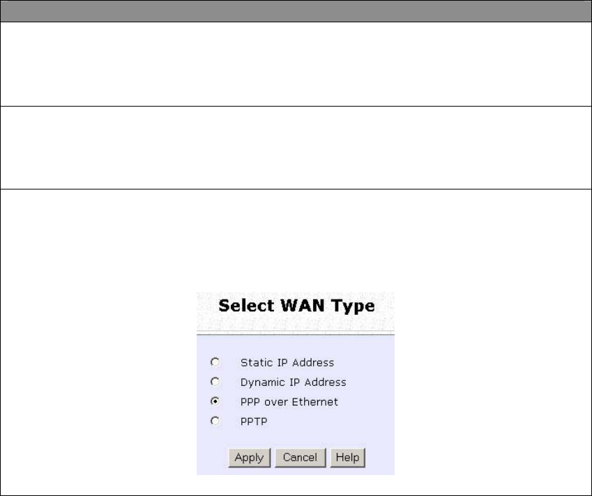
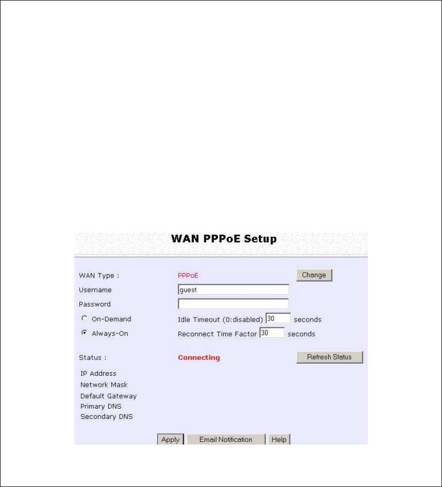
Setup your WAN for ADSL Internet using PPP over Ethernet
If you subscribe to an ADSL service using PPP over Ethernet (PPPoE)
authentication, you can set up your access point’s WAN type as
follows. For example, you may configure an account whose username
is ‘guest’ as described below:
Step 1:
U
Un
nd
de
er
r
CONFIGURATION
o
on
n
t
th
he
e
c
co
om
mm
ma
an
nd
d
m
me
en
nu
u,
,
c
cl
li
ic
ck
k
o
on
n
WAN Setup.
.
Step 2:
A
Ac
cc
ce
es
ss
s
t
th
he
e
Select WAN Type
p
pa
ag
ge
e
a
an
nd
d
c
ch
ho
oo
os
se
e
PPP over Ethernet
b
be
ef
fo
or
re
e
c
cl
li
ic
ck
ki
in
ng
g
t
th
he
e
Apply
b
bu
ut
tt
to
on
n.
.
Page 60
Step 3:
Enter your account name assigned by your ISP (Example: guest) in the
field for U
Us
se
er
rn
na
am
me
e, followed by your account P
Pa
as
ss
sw
wo
or
rd
d.
Select A
Al
lw
wa
ay
ys
s-
-O
On
n if you want your access point to always maintain a
connection with the ISP. Otherwise select O
On
n-
-D
De
em
ma
an
nd
d for the access
point to connect to the ISP automatically when it receives Internet
requests from the PCs in your network.
I
Id
dl
le
e
T
Ti
im
me
eo
ou
ut
t is associated with the O
On
n-
-D
De
em
ma
an
nd
d option, allowing you to
specify the value in seconds after the last Internet activity by which the
access point will disconnect from the ISP. A value of “0” will disable idle
timeout. R
Re
ec
co
on
nn
ne
ec
ct
t
T
Ti
im
me
e
F
Fa
ac
ct
to
or
r is also associated with the A
Al
lw
wa
ay
ys
s-
-o
on
n
option and specifies the maximum time the access point will wait before
reattempting to connect with your ISP. A value of “0” will disable idle
timeout. Click the A
Ap
pp
pl
ly
y button and R
Re
eb
bo
oo
ot
t the access point.
Page 61
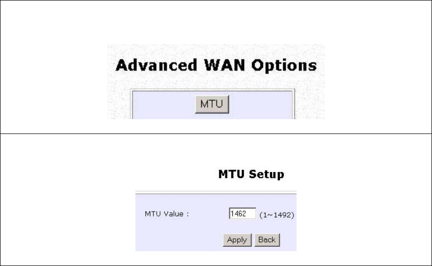
You can limit the maximum size a packet can be in a network by setting
the M
MT
TU
U (Maximum Transmissible Unit).
Click the M
MT
TU
U Button in A
Ad
dv
va
an
nc
ce
ed
d
W
WA
AN
N
O
Op
pt
ti
io
on
ns
s.
The
M
MT
TU
U
V
Va
al
lu
ue
e has a range of 1 to 1492.
Enter the M
MT
TU
U
V
Va
al
lu
ue
e
and click A
Ap
pp
pl
ly
y.
Page 62
Setup your WAN for ADSL Internet using Point-to-Point Tunneling
Protocol (PPTP)
WAN Setup Parameters Example:
• IP Address: 203.120.12.47
• Network Mask: 255.255.255.0
• VPN Server: 203.120.12.15
Step 1:
U
Un
nd
de
er
r
CONFIGURATION
o
on
n
t
th
he
e
c
co
om
mm
ma
an
nd
d
m
me
en
nu
u,
,
c
cl
li
ic
ck
k
o
on
n
WAN Setup.
.
Step 2:
Access the S
Se
el
le
ec
ct
t
W
WA
AN
N
T
Ty
yp
pe
e page and select P
PP
PT
TP
P before clicking the
A
Ap
pp
pl
ly
y button.
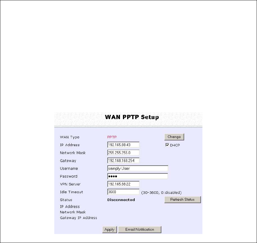
Page 63
Step 3:
Fill in the information provided by your ISP in the I
IP
P
A
Ad
dd
dr
re
es
ss
s,
,
N
Ne
et
tw
wo
or
rk
k
M
Ma
as
sk
k, G
Ga
at
te
ew
wa
ay
y,
,
and V
VP
PN
N
S
Se
er
rv
ve
er
r
fields; select whether to enable D
DH
HC
CP
P;
and click the A
Ap
pp
pl
ly
y button.
Select R
Re
eb
bo
oo
ot
t
S
Sy
ys
st
te
em
m under S
SY
YS
ST
TE
EM
M
T
TO
OO
OL
LS
S and click the R
Re
eb
bo
oo
ot
t button
to effect the settings
The I
Id
dl
le
e
T
Ti
im
me
eo
ou
ut
t setting allows you to specify the value in seconds after
the last Internet activity by which the access point will disconnect from
the ISP. A value of “0” will disable idle timeout.
Page 64
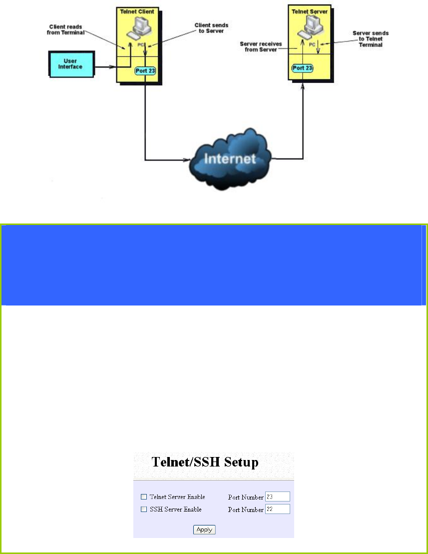
Setup Telnet / SSH
Telnet allows a computer to remotely connect to the access point CLI
(Command Line Interface) for control and monitoring.
SSH (Secure Shell Host) establishes a secure host connection to the
access point CLI for control and monitoring.
Step 1:
Select Telnet/SSH Setup from the CONFIGURATION menu.
Step 2:
1. Select Telnet Server Enable and enter the Port Number to enable.
2. Select SSH Server Enable and enter the Port Number to enable.
Click the Apply button.
Page 65
Step 3:
To add user:
1. Click the Add button.
2. In Add User Entry Page, enter the User Name, Password, and
specify whether the user is granted permission to Read Only or
Read/Write.
3. Click the Apply button.
To Delete User:
1. Select which user to Delete.
2. Click the Delete button.
To Refresh User Management list click the Refresh button.
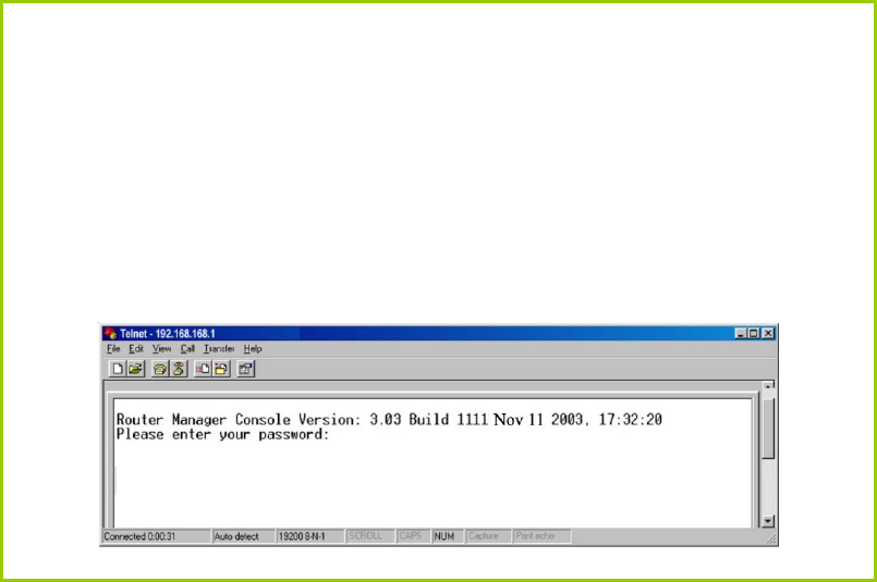
Page 66
Access the TELNET Command Line
Interface
You may connect to the CLI (Command Line Interface) via a
TELNET session to the default IP 192.168.168.1 Microsoft TELNET
command is shown here but any TELNET client can be used.
1. Enter C:\WINDOWS\TELNET 192.168.168.1 at DOS prompt and
the TELNET application will launch and connect.
2. At the login prompt, type in the default password “password”
and press enter. You will then login to the CLI.
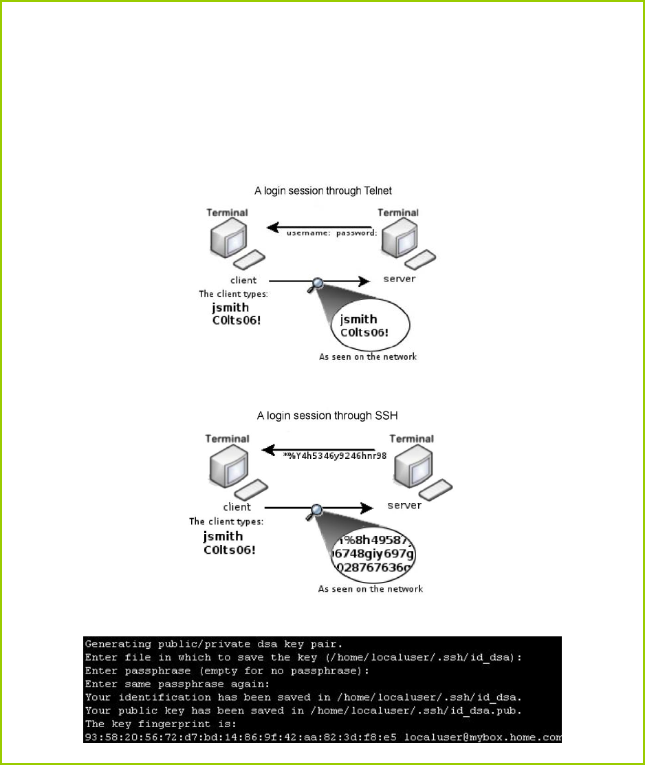
Page 67
Access the Secure Shell Host Command
Line Interface
SSH provides the best remote access security using different forms of
encryption and ciphers to encrypt sessions, and providing better
authentication facilities and features that increase the security of other
protocols.
An encrypted connection like SSH is not viewable on the network. The server
can still read the information, but only after negotiating the encrypted session
with the client.
SSH CLI has a command line interface.
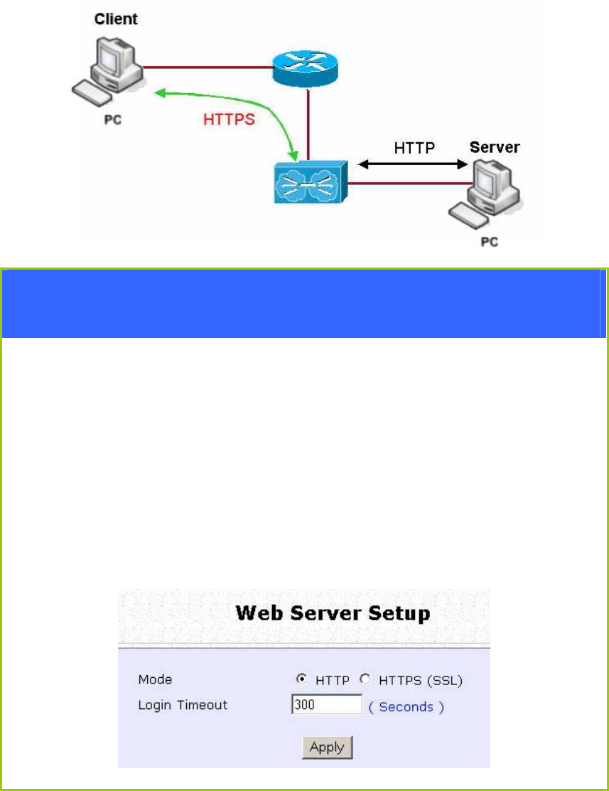
Page 68
Set the WEB Mode
The access point supports HTTPS (SSL) featuring additional
authentication and encryption for secure communication, in addition to
the standard HTTP.
Step 1:
Select Web Management Setup from the CONFIGURATION menu.
Step 2:
1. Select whether to set web server to HTTP or HTTPS (SSL) mode.
2. Specify the Login Timeout (time of inactivity in seconds before
user is automatically logged out).
3. Click Apply.
Changes will be effected after reboot.
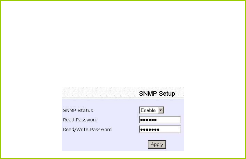
Page 69
Setup SNMP
The Simple Network Management Protocol (SNMP) is a set of
communication protocols that separates the management software
architecture from the hardware device architecture.
Step 1:
Select S
SN
NM
MP
P
S
Se
et
tu
up
p from the C
CO
ON
NF
FI
IG
GU
UR
RA
AT
TI
IO
ON
N menu.
Step 2:
Select E
En
na
ab
bl
le
e from the S
SN
NM
MP
P
S
St
ta
at
te
e drop-down list.
The R
Re
ea
ad
d
P
Pa
as
ss
sw
wo
or
rd
d is set to public while the R
Re
ea
ad
d/
/W
Wr
ri
it
te
e
P
Pa
as
ss
sw
wo
or
rd
d is set to private by
default.
Step 3:
Click on the A
Ap
pp
pl
ly
y button.
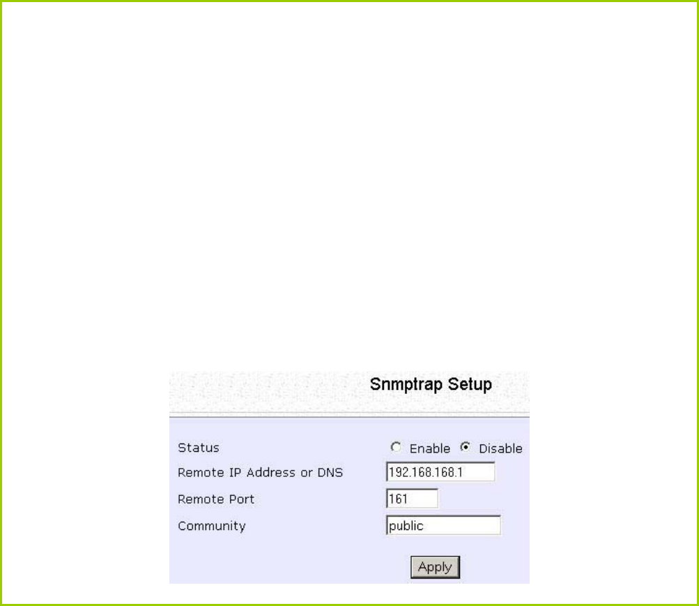
Page 70
Setup SNMP Trap
The SNMP Trap saves network resources through eliminating the need
for unnecessary SNMP requests by providing notification of significant
network events with unsolicited SNMP messages.
Step 1:
Select S
SN
NM
MP
P
S
Se
et
tu
up
p from the C
CO
ON
NF
FI
IG
GU
UR
RA
AT
TI
IO
ON
N menu.
Step 2:
1. Select whether to E
En
na
ab
bl
le
e or D
Di
is
sa
ab
bl
le
e the SNMP Trap.
2. Enter the
R
Re
em
mo
ot
te
e
I
IP
P
A
Ad
dd
dr
re
es
ss
s
o
or
r
D
DN
NS
S.
3. Enter the
R
Re
em
mo
ot
te
e
P
Po
or
rt
t.
This is the port number of the SNMP manager.
4. Enter the
C
Co
om
mm
mu
un
ni
it
ty
y.
This is used to authenticate message, and is included in every packet
that is transmitted between the SNMP manager and agent.
5. Click on the A
Ap
pp
pl
ly
y button.
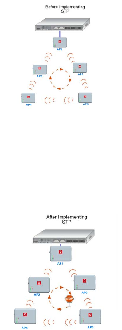
Page 71
Setup STP
(Available in Access Point, Transparent Client, and Repeater modes)
Spanning Tree Protocol (STP) prevents broadcast storms when there are
redundant paths in the network. STP creates a tree that spans all
devices in an extended network, forcing redundant paths into a
standby state, but establishing the redundant links as backup in case
the active link should fail. If STP costs change, or if one network
segment in the STP becomes unreachable, the spanning tree algorithm
reconfigures the spanning tree topology and re-establishes the
connection by activating the standby path. The path with the smallest
cost will be used and extra redundant paths will be disabled.
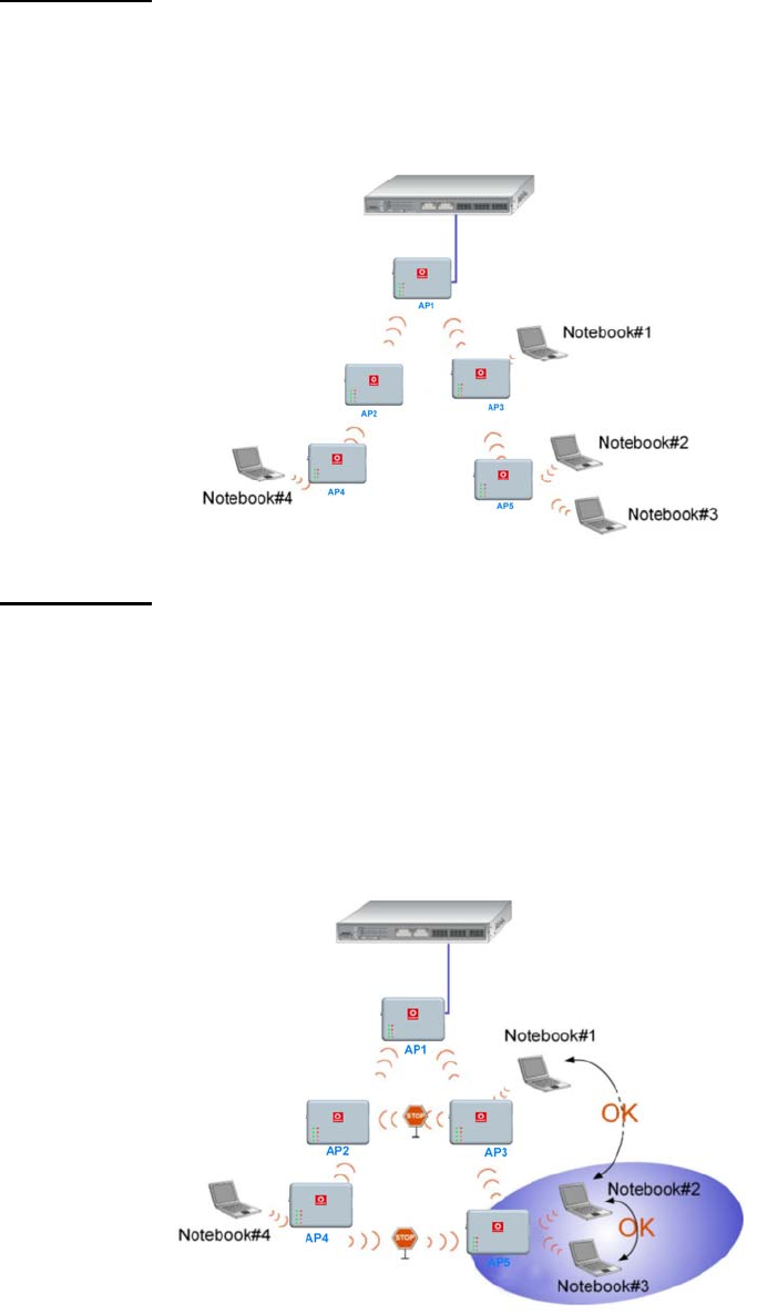
Page 72
Scenario #1 – (No STP)
With no STP, all clients (Notebook#1, #2, #3, #4) can access one
another, resulting in low data security. Due to the redundant paths,
broadcast packets will be duplicated and forwarded endlessly,
resulting in a broadcast storm.
Scenario #2 – (With STP)
With STP, extra redundant network paths between access points will be
disabled, hence preventing multiple active network paths in between
any 2 access points. If one of the access points is down, the STP
algorithm will reactivate one of the redundant paths so that the
network connection will not be lost. All wireless users will be able to
communicate with each other if they are associated to the access
points that are in the same zone.
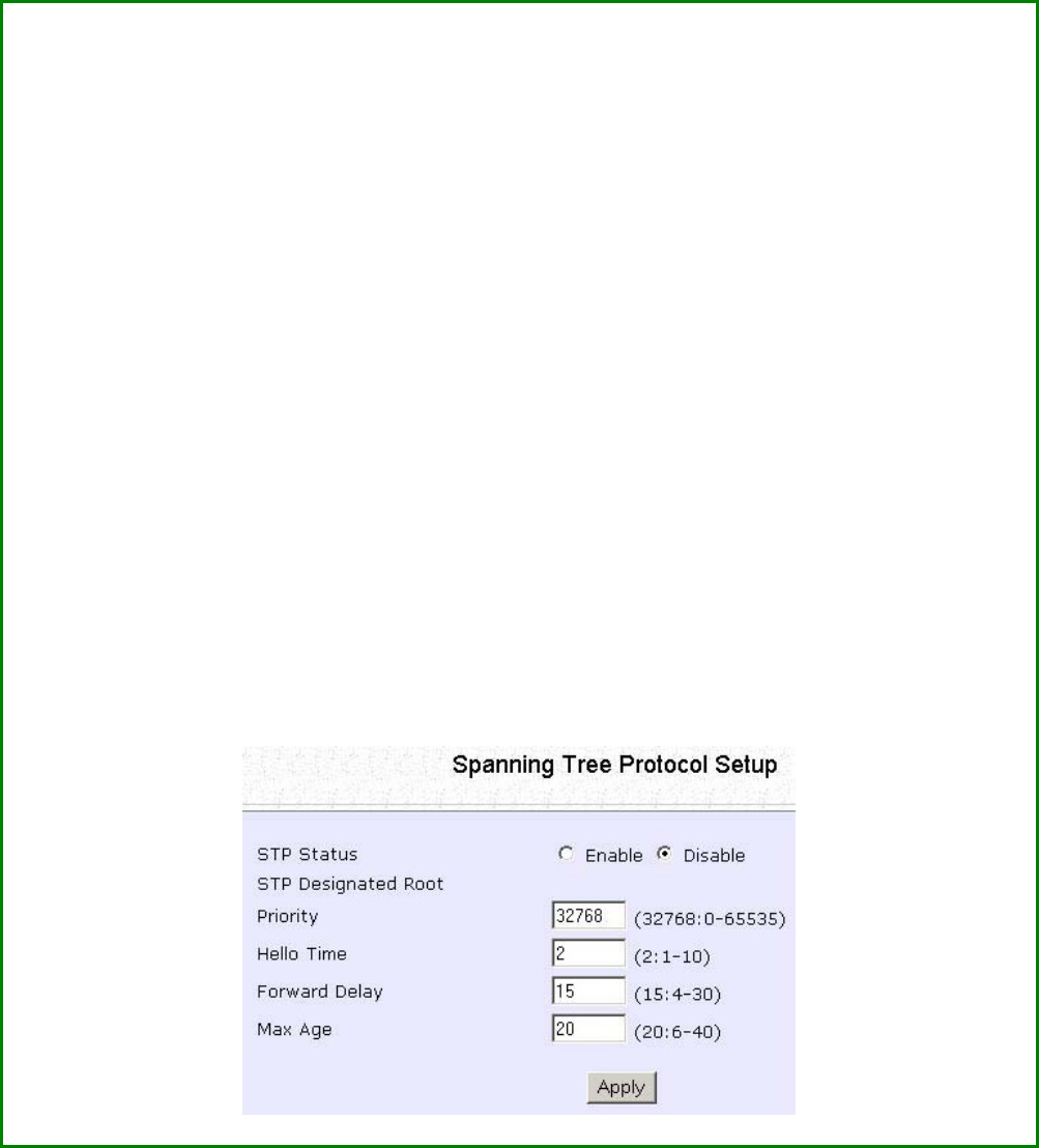
Page 73
S
St
te
ep
p
1
1:
:
Select STP
S
Se
et
tu
up
p from the C
CO
ON
NF
FI
IG
GU
UR
RA
AT
TI
IO
ON
N menu.
S
St
te
ep
p
2
2:
:
Select the S
ST
TP
P
S
St
ta
at
tu
us
s E
En
na
ab
bl
le
e radio button, fill in the fields, and click on the A
Ap
pp
pl
ly
y
button to update the changes.
Priority: (Default: 32768, Range: 0 – 65535)
This is the relative priority.
The lowest priority will be elected as the root.
Hello Time: (Default: 2, Range: 1 – 10)
This is the time interval in seconds whereby a hello packet is sent out. Hello packets
are used to communicate information about the topology throughout the entire STP
network.
Forward Delay: (Default: 15, Range: 4 – 30)
This is the time that is spent in the listening and learning state.
Max Age: (Default: 20, Range: 6 – 40)
The max age timer controls the maximum length of time that passes before a port
saves its configuration information.

Page 74
Use MAC Filtering
MAC Filtering acts as a security measure by restricting user network
access according to MAC address. Each WLAN or radio card supports
up to 16 virtual access points and has its own MAC address listing.
NOTE
MAC Filtering will not filter any MAC address from the Ethernet
port.

Page 75
Add a MAC Address to the MAC Address
List
S
St
te
ep
p
1
1:
:
Select M
MA
AC
C
F
Fi
il
lt
te
er
ri
in
ng
g from W
WL
LA
AN
N
S
Se
et
tu
up
p.
The MAC Address Filtering page displays.
In this page you may also set the MAC Filtering Status to E
En
na
ab
bl
le
e
or
D
Di
is
sa
ab
bl
le
e
for access points and set the Policy to either A
Ac
cc
ce
ep
pt
t
or D
De
en
ny
y
MAC addresses.
MAC Filtering set to E
En
na
ab
bl
le
e
with Policy to A
Ac
cc
ce
ep
pt
t only
the MAC addresses in the MAC Filter Address List and
deny all other MAC addresses.
MAC Filtering set to E
En
na
ab
bl
le
e
with Policy to D
De
en
ny
y all the
MAC addresses in the MAC Filter Address List and
accept all other MAC addresses.
MAC Filtering set to D
Di
is
sa
ab
bl
le
e. Whether Policy is set to
E
En
na
ab
bl
le
e or D
De
en
ny
y does not matter.
MAC Filtering set to D
Di
is
sa
ab
bl
le
e. Whether Policy is set to
E
En
na
ab
bl
le
e or D
De
en
ny
y does not matter.
Click the E
Ed
di
it
t button.
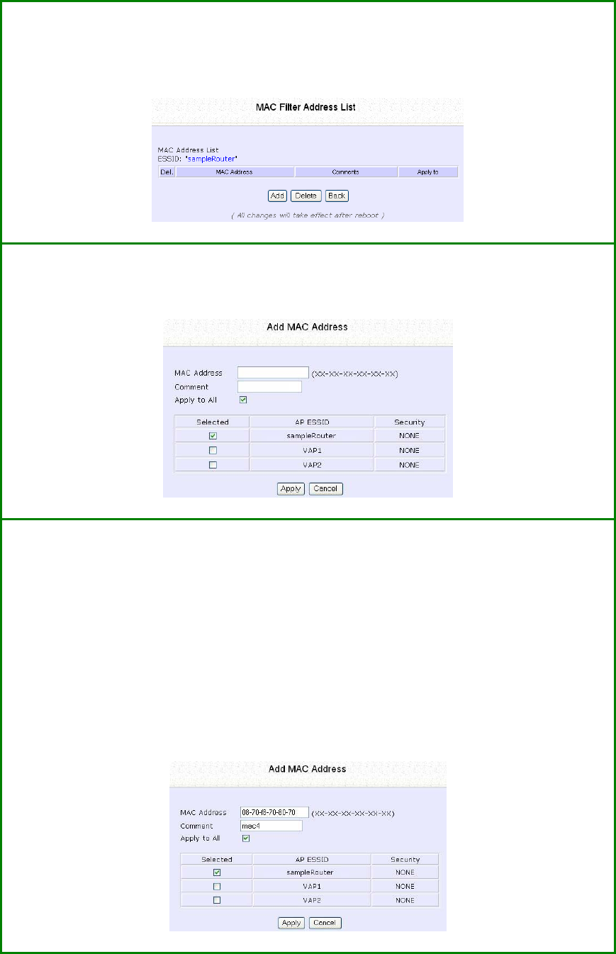
Page 76
S
St
te
ep
p
2
2:
:
MAC Filter Address List page displays.
Click the A
Ad
dd
d
button.
S
St
te
ep
p
3
3:
:
The Add MAC Address page displays.
S
St
te
ep
p
4
4:
:
Enter the MAC Address of the client in the format xx-xx-xx-xx-xx-xx,
where x can take any value from 0 to 9 or a to f.
Enter the Comment. This describes the MAC Address you have entered.
To apply to all virtual access points, check A
Ap
pp
pl
ly
y
t
to
o
A
Al
ll
l.
To apply to specific virtual access point, select the checkbox of the
corresponding access point.
Click the A
Ap
pp
pl
ly
y
button.
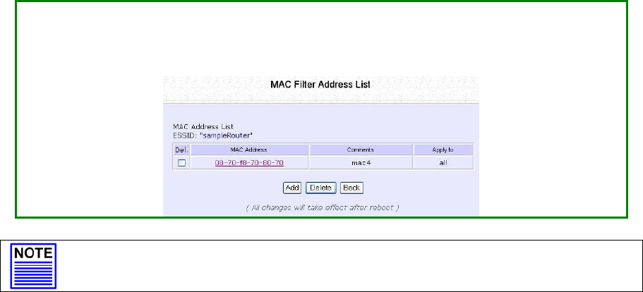
Page 77
S
St
te
ep
p
5
5:
:
MAC Filter Address List page displays with updated MAC Address List.
NOTE
Please reboot to effect all changes and new MAC address entries.
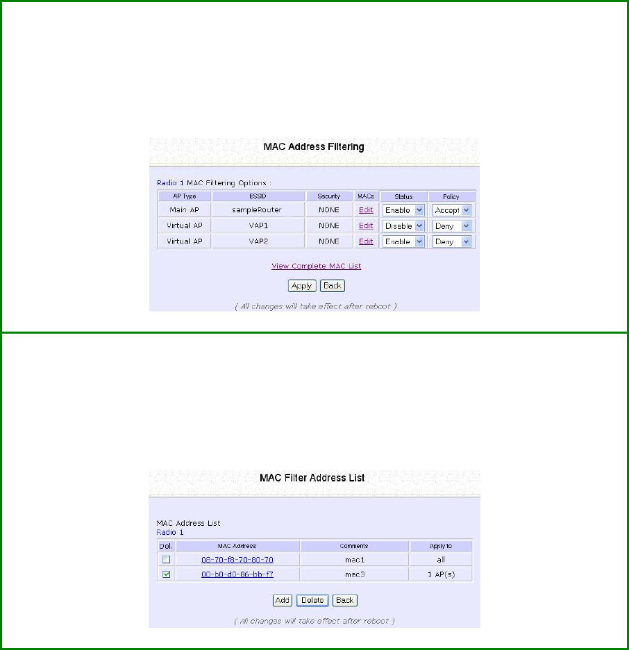
Page 78
Delete a MAC Address from All Access
Points
S
St
te
ep
p
1
1:
:
Select M
MA
AC
C
F
Fi
il
lt
te
er
ri
in
ng
g from W
WL
LA
AN
N
S
Se
et
tu
up
p.
The MAC Address Filtering page displays.
Select V
Vi
ie
ew
w
C
Co
om
mp
pl
le
et
te
e
M
MA
AC
C
L
Li
is
st
t.
.
S
St
te
ep
p
2
2:
:
The MAC Filter Address List page displays.
Select the checkbox of the MAC address you wish to delete.
Click the D
De
el
le
et
te
e
button.
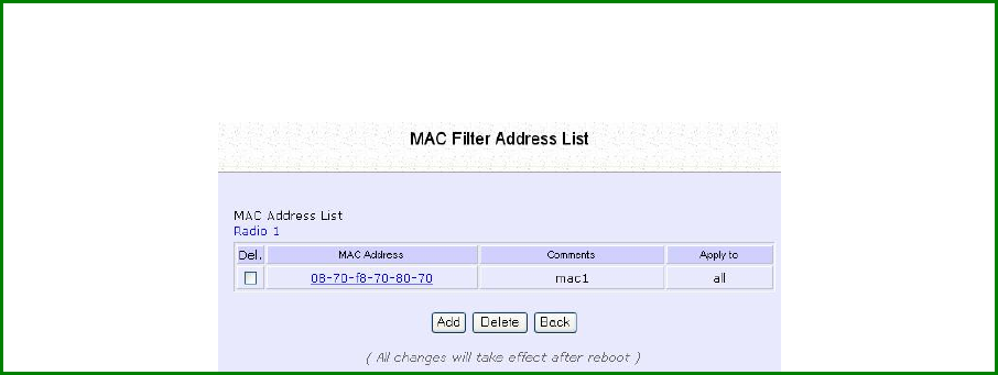
Page 79
S
St
te
ep
p
3
3:
:
The MAC Filter Address List page displays with updated MAC Address List.
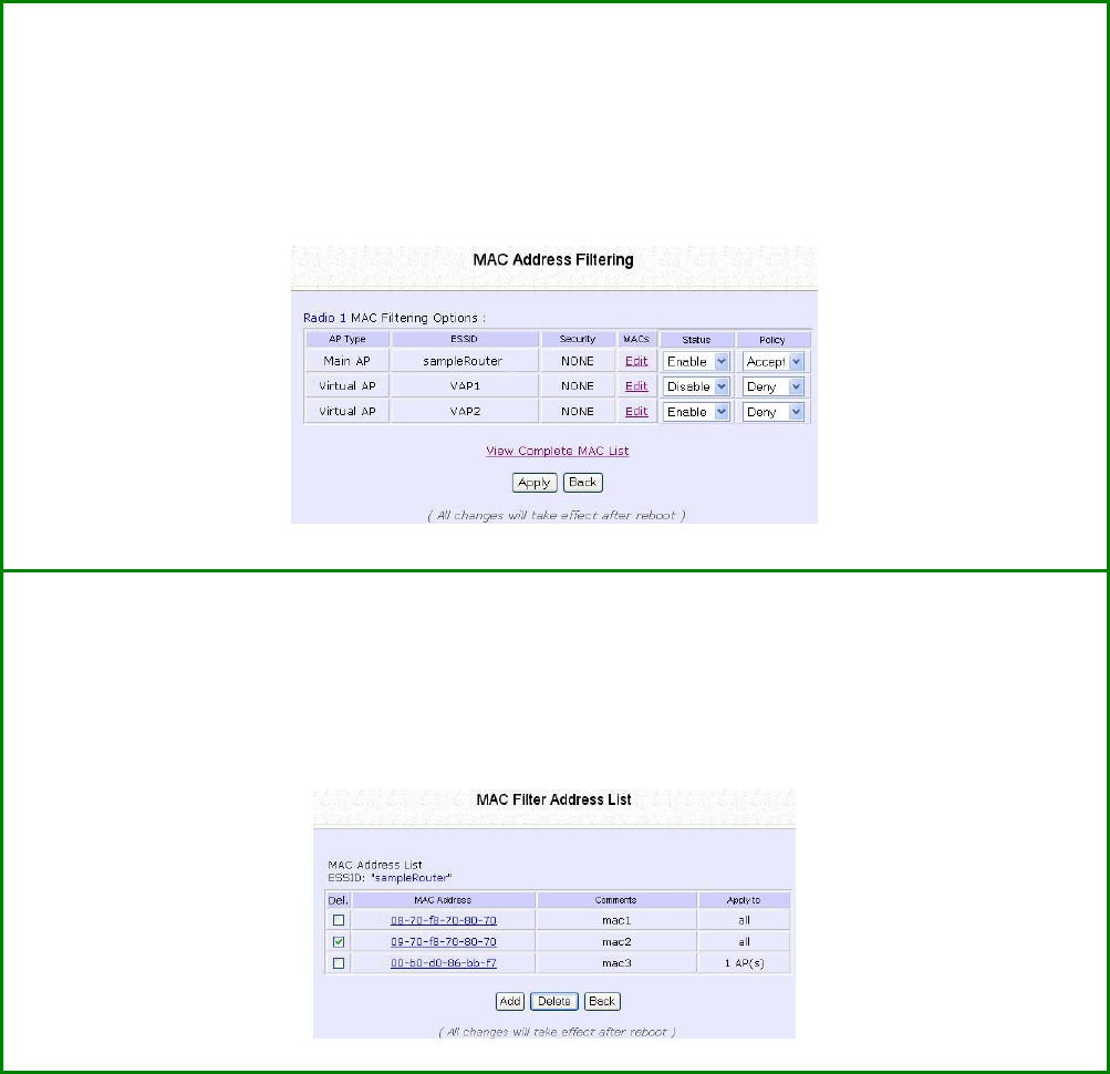
Page 80
Delete a MAC Address from Individual
Access Point
S
St
te
ep
p
1
1:
:
Select M
MA
AC
C
F
Fi
il
lt
te
er
ri
in
ng
g from W
WL
LA
AN
N
S
Se
et
tu
up
p.
The MAC Address Filtering page displays.
Select E
Ed
di
it
t for the corresponding access point.
S
St
te
ep
p
2
2:
:
The MAC Filter Address List page displays.
Select the checkbox of the MAC address you wish to delete.
Click the D
De
el
le
et
te
e
button.

Page 81
S
St
te
ep
p
3
3:
:
The MAC Filter Address List page displays with updated MAC Address List.
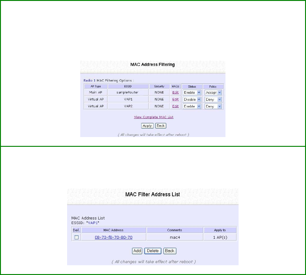
Page 82
Edit MAC Address from the MAC Address
List
S
St
te
ep
p
1
1:
:
Select M
MA
AC
C
F
Fi
il
lt
te
er
ri
in
ng
g from W
WL
LA
AN
N
S
Se
et
tu
up
p.
The MAC Address Filtering page displays.
Select E
Ed
di
it
t.
S
St
te
ep
p
2
2:
:
MAC Filter Address List page displays.
Select the MAC address to edit.
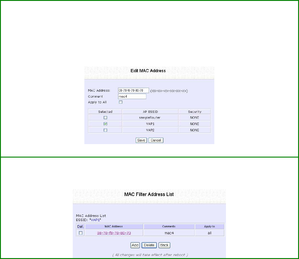
Page 83
S
St
te
ep
p
3
3:
:
The Edit MAC Address page displays.
Edit the MAC address settings accordingly.
Click the S
Sa
av
ve
e button.
S
St
te
ep
p
4
4:
:
The MAC Filter Address List page displays with updated MAC Address List.
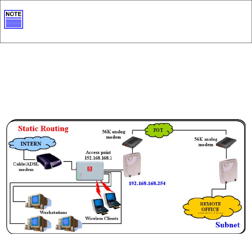
Page 84
Perform Advanced Configuration
Setup Routing
(Available in Wireless Routing Client and Gateway modes)
The access point allows you to add a static routing entry into its routing
table to re-route IP packets to another access point. This is useful if your
network has more than one access point.
Important:
You do NOT need to set any routing information if you are simply
configuring the access point for broadband Internet sharing. The
wrong routing configuration might cause the access point to
function improperly.
In this network, the main office of subnet 192.168.168.0 contains two
routers: the office is connected to the Internet via the access point
(192.168.168.1) and to the remote office via 192.168.168.254 The
remote office resides on subnet 192.168.100.0
You can add a static routing entry into the access point routing table
so that IP packets from the clients in the main office with a destination
IP address of 192.168.100.X where X is any number from 2 to 254 will be
re-routed to the router, which acts as the gateway to that subnet.
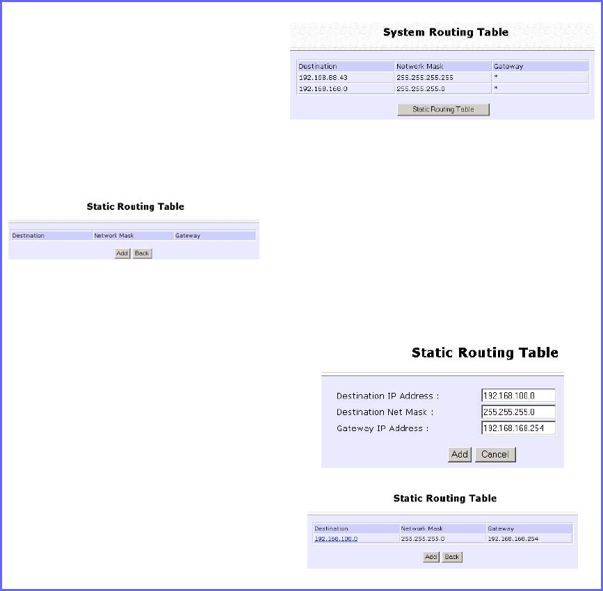
Page 85
Configure Static Routing
Step 1:
Select R
Ro
ou
ut
ti
in
ng
g from the
C
CO
ON
NF
FI
IG
GU
UR
RA
AT
TI
IO
ON
N command
menu. The S
Sy
ys
st
te
em
m
R
Ro
ou
ut
ti
in
ng
g
T
Ta
ab
bl
le
e page displays. Initially
the table contains the default
routing entries of the access
point.
Step 2:
Click on the S
St
ta
at
ti
ic
c
R
Ro
ou
ut
ti
in
ng
g
T
Ta
ab
bl
le
e
button, and then click the Add
button.
Step 3:
Enter the D
De
es
st
ti
in
na
at
ti
io
on
n
I
IP
P
A
Ad
dd
dr
re
es
ss
s,
,
D
De
es
st
ti
in
na
at
ti
io
on
n
N
Ne
et
t
M
Ma
as
sk
k,
and G
Ga
at
te
ew
wa
ay
y
I
IP
P
A
Ad
dd
dr
re
es
ss
s, and
click the A
Ad
dd
d button.
The S
St
ta
at
ti
ic
c
R
Ro
ou
ut
ti
in
ng
g
T
Ta
ab
bl
le
e
reflects the entry.
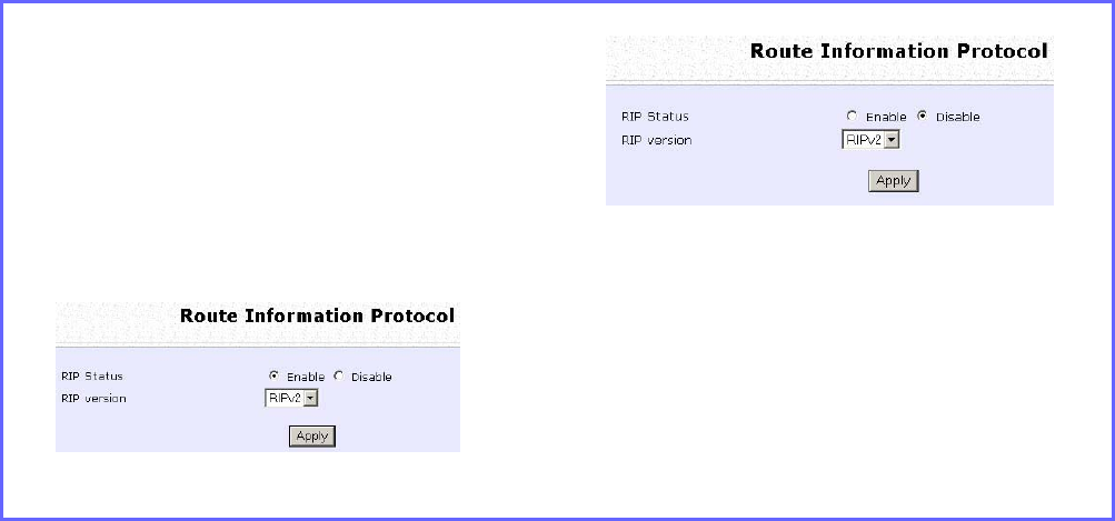
Page 86
Use Routing Information Protocol
(Available in Wireless Routing Client and Gateway modes)
RIP (Routing Information Protocol) allows information to be exchanged
within a set of routers under the same administration.
RIPv1 bases the path used to pass traffic between routers on the fewest
number of hops between the source and destination IP addresses
within a packet. Routers broadcast RIPv1 information on all router
interfaces every 30 seconds and process the information from other
routers to determine if a better path is available. RIPv2 is more secure,
and performs broadcasting and the assignment of IP address more
efficiently.
Step 1:
Under the C
CO
ON
NF
FI
IG
GU
UR
RA
AT
TI
IO
ON
N
command menu, click on R
Ro
ou
ut
ti
in
ng
g to
be brought to R
Ro
ou
ut
te
e
I
In
nf
fo
or
rm
ma
at
ti
io
on
n
P
Pr
ro
ot
to
oc
co
ol
l.
Step 2:
Select to E
En
na
ab
bl
le
e
R
RI
IP
P
S
St
ta
at
tu
us
s.
Select either RIPv1 or RIPv2.
On this page, click the Apply button.
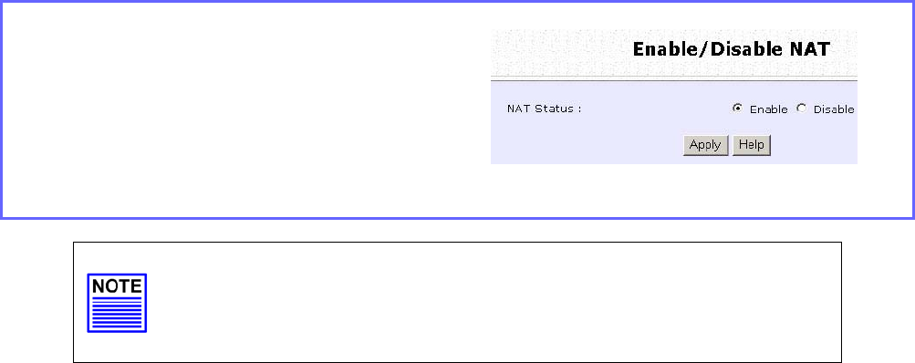
Page 87
Use Network Address Translation
(Available in Wireless Routing Client and Gateway modes)
NAT (Network Address Translation) allows multiple PCs in a private
network to share a single public IP address by using different TCP ports
to identify requests coming from different PCs, and is enabled by
default. Computers in the private LAN behind the access point will not
be directly accessible from the Internet. However, employing virtual
servers allows the hosting of Internet servers by using IP/ Port Forwarding
and De-Militarized Zone hosting.
Step 1:
Select N
NA
AT
T from the
C
CO
ON
NF
FI
IG
GU
UR
RA
AT
TI
IO
ON
N command menu.
To disable it, select the D
Di
is
sa
ab
bl
le
e radio
button.]
Step 2:
Click the A
Ap
pp
pl
ly
y button to effect the
setting.
Important:
NAT provides for effective broadband Internet sharing; do
NOT disable NAT unless it is absolutely necessary.
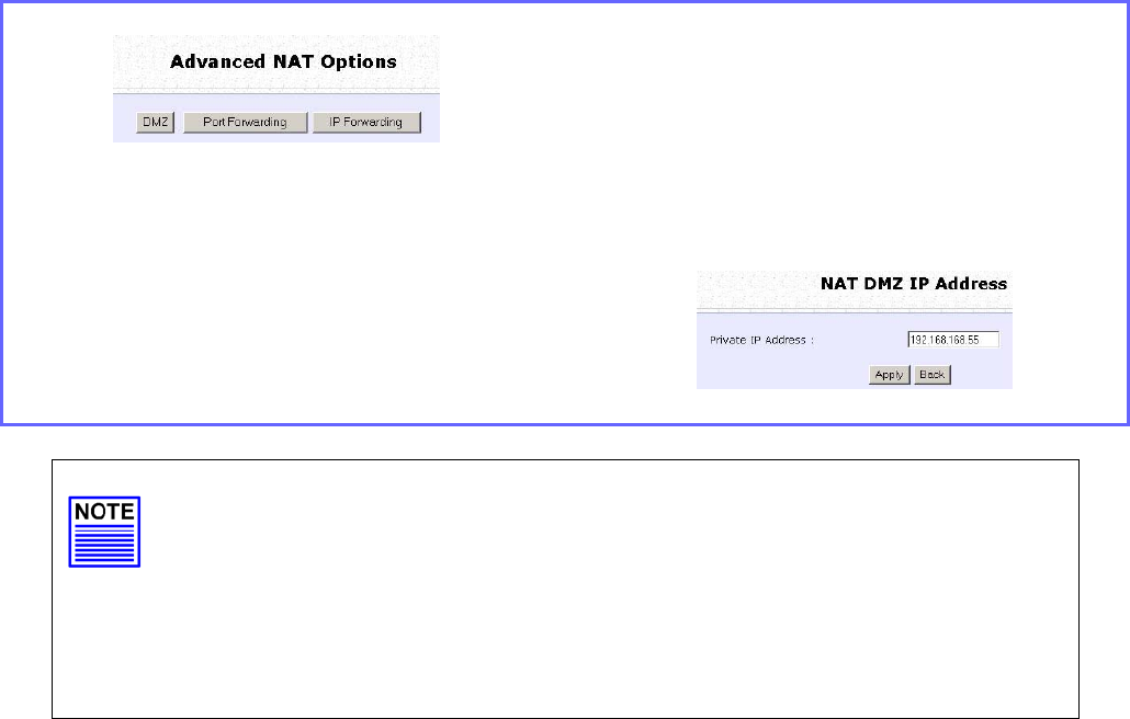
Page 88
Configure Virtual Servers Based on DMZ
Host
DMZ (De-Militarized Zone) makes specific PCs in a NAT-enabled
network directly accessible from the Internet.
With NAT, the access point keeps track of which client is using which
port number and forwards Internet replies to the client according to
the port number in the reply packet. Reply packets with unrecognized
port numbers are discarded, but with DMZ, these packets are
forwarded to the DMZ-enabled PC instead.
Step 1:
Select N
NA
AT
T from the C
CO
ON
NF
FI
IG
GU
UR
RA
AT
TI
IO
ON
N
command menu.
Step 2:
Click on the D
DM
MZ
Z button in A
Ad
dv
va
an
nc
ce
ed
d
N
NA
AT
T
O
Op
pt
ti
io
on
ns
s.
Step 3:
Enter the P
Pr
ri
iv
va
at
te
e
I
IP
P
A
Ad
dd
dr
re
es
ss
s of the DMZ
host on the N
NA
AT
T
D
DM
MZ
Z
I
IP
P
A
Ad
dd
dr
re
es
ss
s page.
To disable DMZ, enter 0
0.
.0
0.
.0
0.
.0
0
Click the A
Ap
pp
pl
ly
y button.
NOTE
1. DMZ may not function properly if the DMZ host IP address
is changed due to DHCP, therefore, Static IP Address
configuration is recommended for the DMZ host.
2. Please note that the DMZ host is susceptible to malicious
attacks as ALL of its ports are exposed to the Internet.
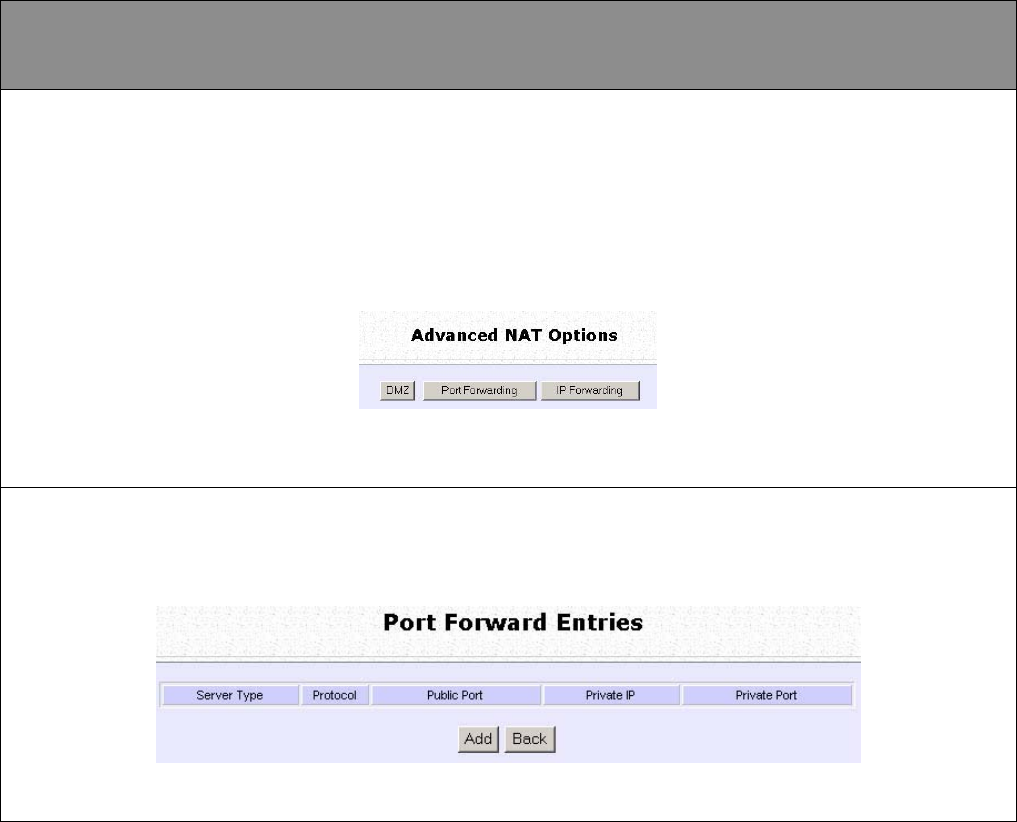
Page 89
Configure Virtual Servers Based on Port
Forwarding
Virtual Server based on Port Forwarding forwards Internet requests arriving at
the access point WAN interface to specific PCs in the private network based
on their ports.
Step 1:
Select N
NA
AT
T from the C
CO
ON
NF
FI
IG
GU
UR
RA
AT
TI
IO
ON
N command menu.
Step 2:
Click the P
Po
or
rt
t
F
Fo
or
rw
wa
ar
rd
di
in
ng
g button in A
Ad
dv
va
an
nc
ce
ed
d
N
NA
AT
T
O
Op
pt
ti
io
on
ns
s.
Step 2:
C
Cl
li
ic
ck
k
t
th
he
e
Add
b
bu
ut
tt
to
on
n
o
on
n
t
th
he
e
Port Forward Entries
p
pa
ag
ge
e.
.
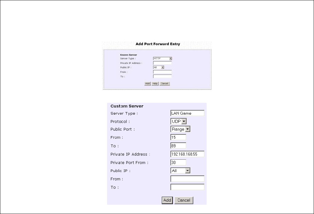
Page 90
Step 3:
In the A
Ad
dd
d
P
Po
or
rt
t
F
Fo
or
rw
wa
ar
rd
d
E
En
nt
tr
ry
y page, you can set up a Virtual Server for a K
Kn
no
ow
wn
n
S
Se
er
rv
ve
er
r type by selecting from a drop-down menu or you can define a C
Cu
us
st
to
om
m
S
Se
er
rv
ve
er
r.

Page 91
Known
Server
Server Type
:
Select from the drop-down list of known server types:
• HTTP
• FTP
• POP3
• Netmeeting
Private IP
Address
:
Specify the LAN IP address of the server PC running within the
private network.
Public IP
:
Select All, Single, or Range from the dropdown list.
From
:
Enter the beginning of the range.
To
:
Enter the end of the range.
Custom
Server
Server Type
:
Define a name for the server type you wish to configure.
Protocol
:
Select either TCP or UDP protocol type from the dropdown list.
Public Port
:
Select whether to define a single port or a range of public
port numbers to accept.
From
:
Starting public port number
To
:
Ending public port number. If the Public Port type is Single, this
field will be ignored.
Private IP
Address
:
Specify the IP address of the server PC running within the
private network.
Private Port
From
:
Starting private port number. The ending private port number
will be calculated automatically according to the public port
range.
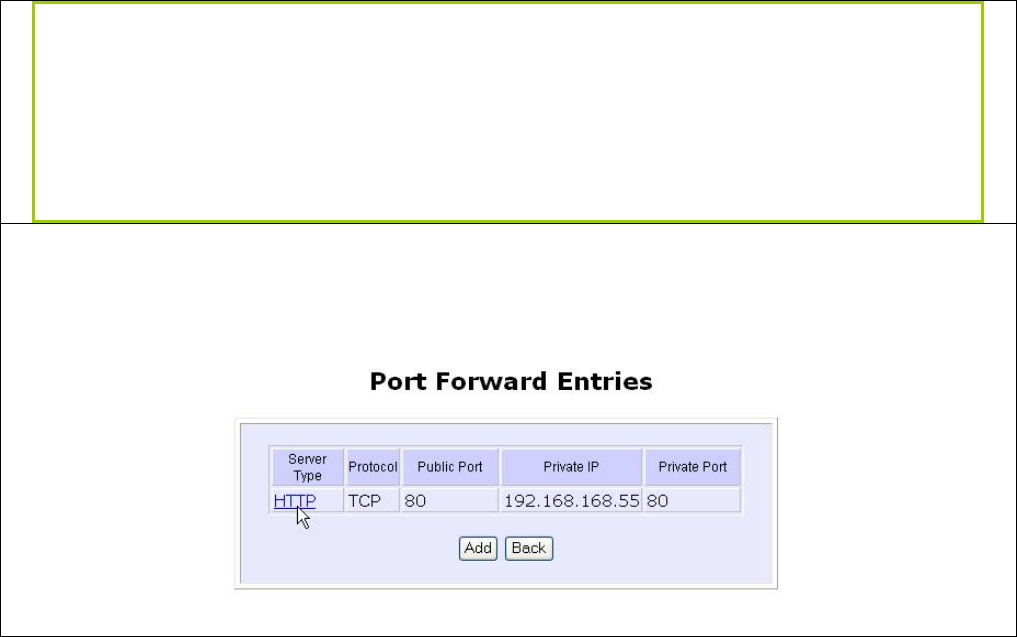
Page 92
Public IP
:
Select All, Single, or Range from the dropdown list.
From
:
Enter the beginning of the range.
To
:
Enter the end of the range.
For example to set up a web server on a PC with IP address 192.168.168.55, set the
S
Se
er
rv
ve
er
r
T
Ty
yp
pe
e as HTTP and set the P
Pr
ri
iv
va
at
te
e
I
IP
P
A
Ad
dd
dr
re
es
ss
s as 1
19
92
2.
.1
16
68
8.
.1
16
68
8.
.5
55
5, then click on the
A
Ad
dd
d button.
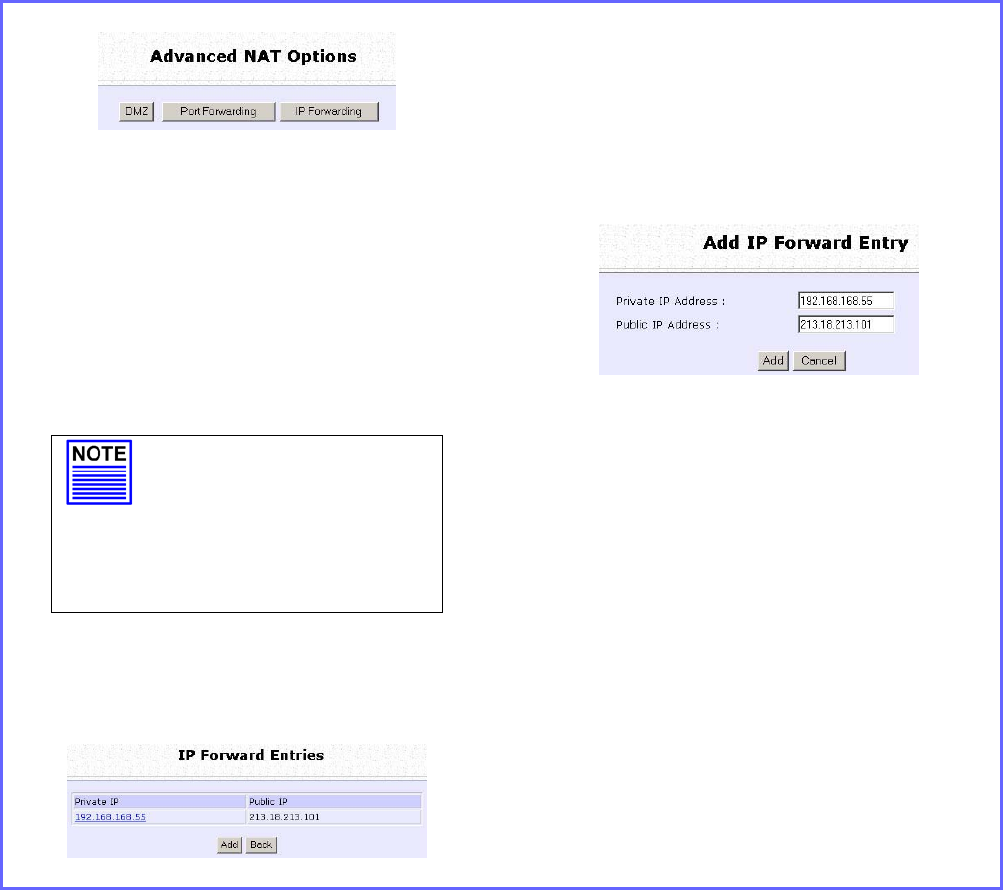
Page 93
Configure Virtual Servers based on IP
Forwarding
If you are subscribed to more than one IP address from your ISP, virtual
servers based on IP forwarding can forward all Internet requests
regardless of the port number to defined computers in the private
network.
Step 1:
Select N
NA
AT
T from the C
CO
ON
NF
FI
IG
GU
UR
RA
AT
TI
IO
ON
N
command menu.
Step 2:
Click the I
IP
P
F
Fo
or
rw
wa
ar
rd
di
in
ng
g button in
A
Ad
dv
va
an
nc
ce
ed
d
N
NA
AT
T
O
Op
pt
ti
io
on
ns
s.
Step 3:
In the A
Ad
dd
d
I
IP
P
F
Fo
or
rw
wa
ar
rd
d
E
En
nt
tr
ry
y page, enter
the P
Pr
ri
iv
va
at
te
e
I
IP
P
A
Ad
dd
dr
re
es
ss
s and Public
I
IP
P
A
Ad
dd
dr
re
es
ss
s.
In this example, we would like all
requests for 213.18.213.101 to be
forwarded to a PC with P
Pr
ri
iv
va
at
te
e
I
IP
P
A
Ad
dd
dr
re
es
ss
s 192.168.168.55.
NOTE
Please ensure that
you are subscribed to
the P
Pu
ub
bl
li
ic
c
I
IP
P
A
Ad
dd
dr
re
es
ss
s
you intend to forward
from.
Step 4:
Click the A
Ad
dd
d button.
Step 5:
The I
IP
P
F
Fo
or
rw
wa
ar
rd
d
E
En
nt
tr
ri
ie
es
s page reflects
your new addition.
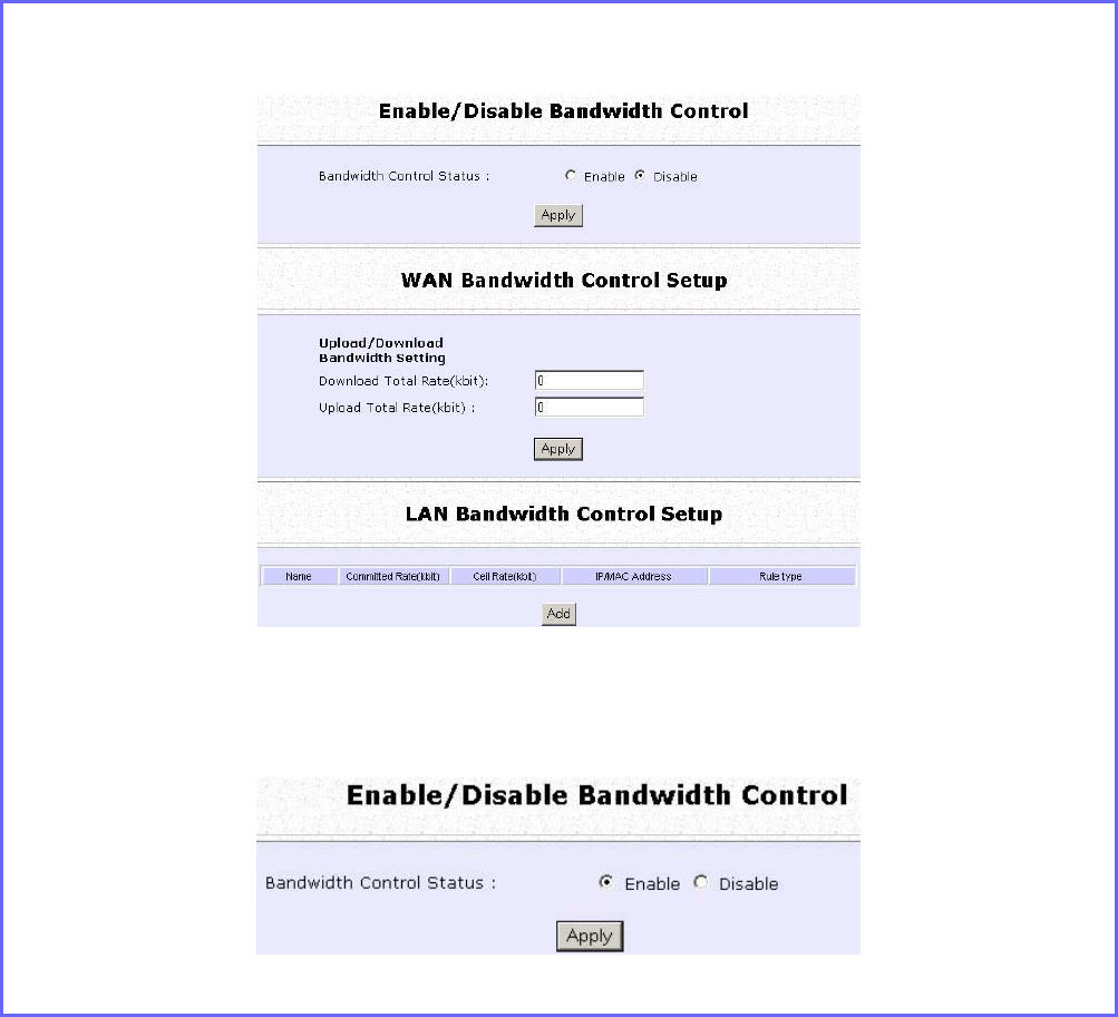
Page 94
Control the Bandwidth Available
(Available in Wireless Routing Client and Gateway modes)
Keep in control of your LAN network in router operation. Bandwidth
access to the Internet on both the wireless LAN connection in Gateway
mode and the Ethernet connection in Wireless Routing Client Mode
can be managed.
Enable Bandwidth Control
Step 1:
Select B
Ba
an
nd
dw
wi
id
dt
th
h
C
Co
on
nt
tr
ro
ol
l from the C
CO
ON
NF
FI
IG
GU
UR
RA
AT
TI
IO
ON
N command menu.
Step 2:
B
Ba
an
nd
dw
wi
id
dt
th
h
C
Co
on
nt
tr
ro
ol
l is disabled by default, select E
En
na
ab
bl
le
e, and click the A
Ap
pp
pl
ly
y button.
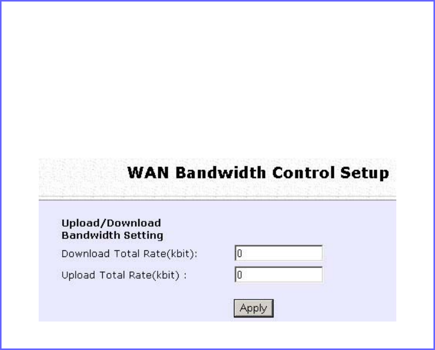
Page 95
Configure WAN Bandwidth Control
The Upload / Download Bandwidth Setting can limit throughput to the
defined rates regardless of the number of connections.
Step 1:
Select W
WA
AN
N
B
Ba
an
nd
dw
wi
id
dt
th
h
C
Co
on
nt
tr
ro
ol
l
S
Se
et
tu
up
p from the B
Ba
an
nd
dw
wi
id
dt
th
h
C
Co
on
nt
tr
ro
ol
l sub-
menu from the C
CO
ON
NF
FI
IG
GU
UR
RA
AT
TI
IO
ON
N command menu.
Step 2:
Enter the D
Do
ow
wn
nl
lo
oa
ad
d
T
To
ot
ta
al
l
R
Ra
at
te
e and U
Up
pl
lo
oa
ad
d
T
To
ot
ta
al
l
R
Ra
at
te
e.
The default values are 0, which indicates that there is no bandwidth
limit.
Click the A
Ap
pp
pl
ly
y button.
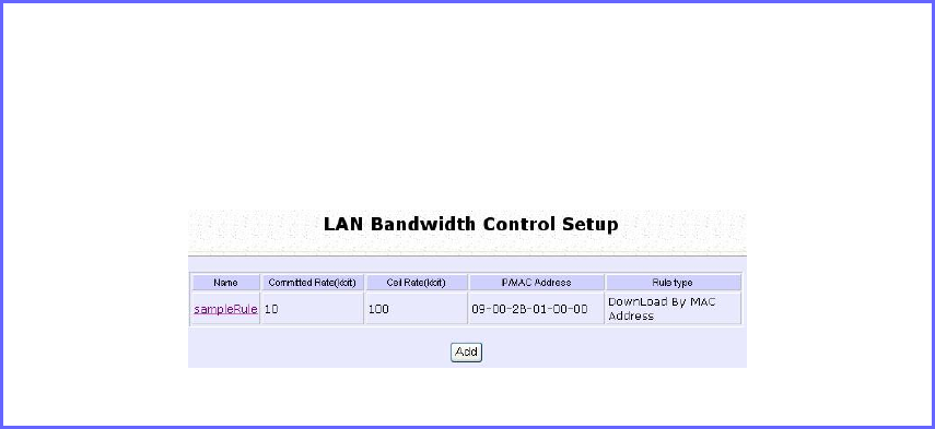
Page 96
Configure LAN Bandwidth Control
Bandwidth Control can also limit LAN users’ throughput.
Step 1:
Select L
LA
AN
N
B
Ba
an
nd
dw
wi
id
dt
th
h
C
Co
on
nt
tr
ro
ol
l
S
Se
et
tu
up
p from the B
Ba
an
nd
dw
wi
id
dt
th
h
C
Co
on
nt
tr
ro
ol
l sub-
menu from the C
CO
ON
NF
FI
IG
GU
UR
RA
AT
TI
IO
ON
N command menu.
Step 2:
Click the A
Ad
dd
d button to create the bandwidth rule for LAN user.