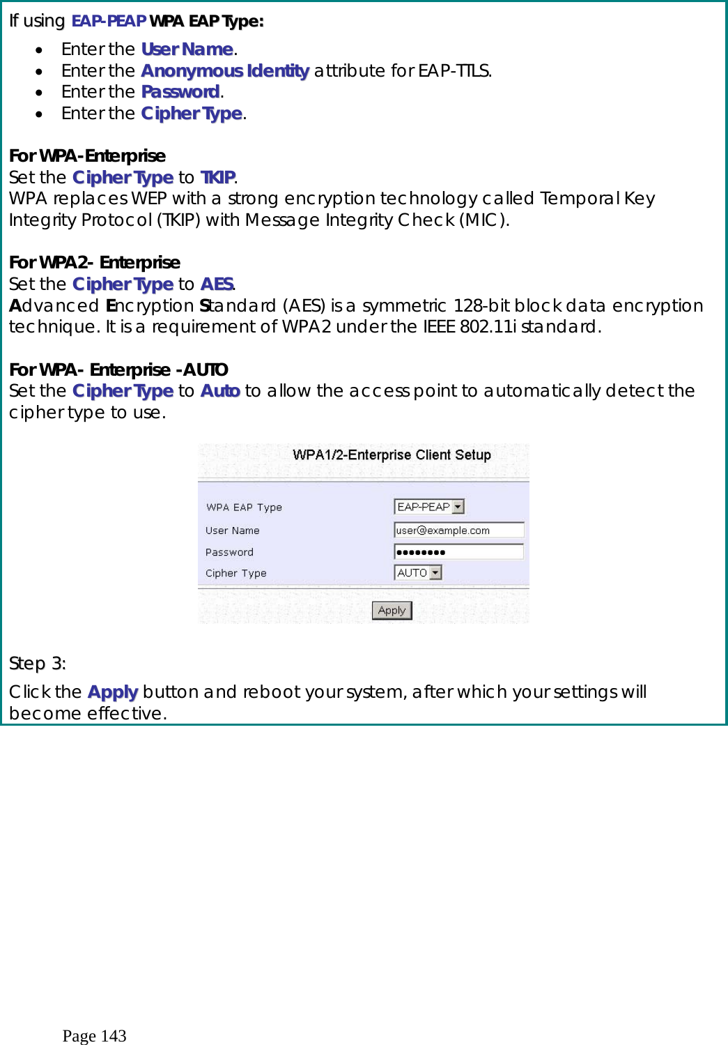
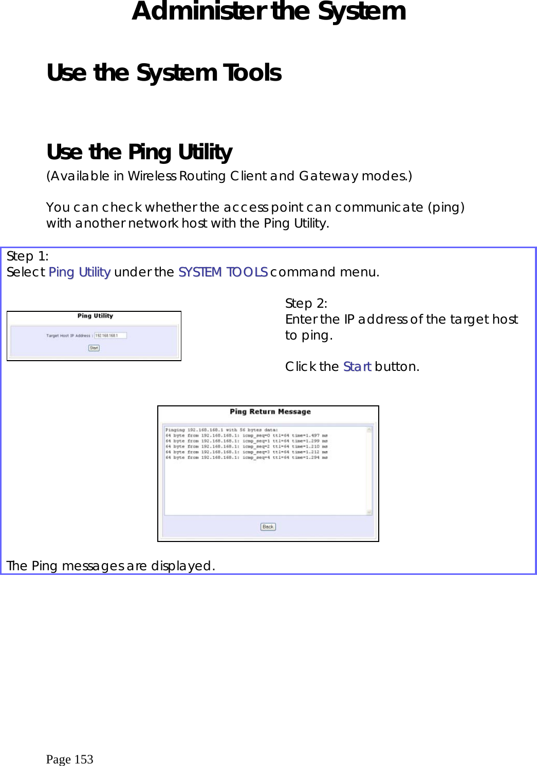
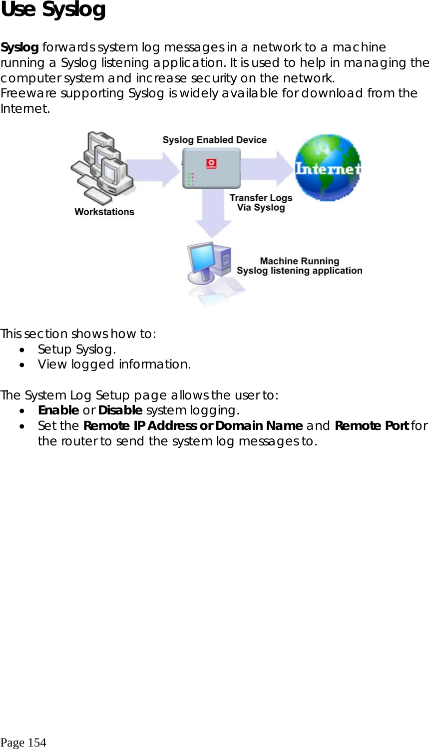
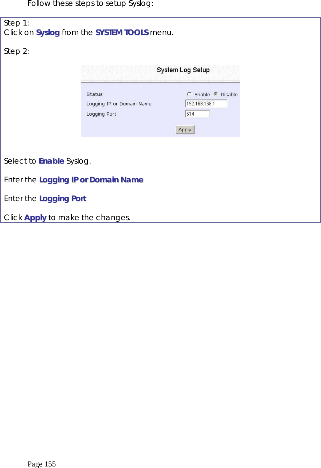
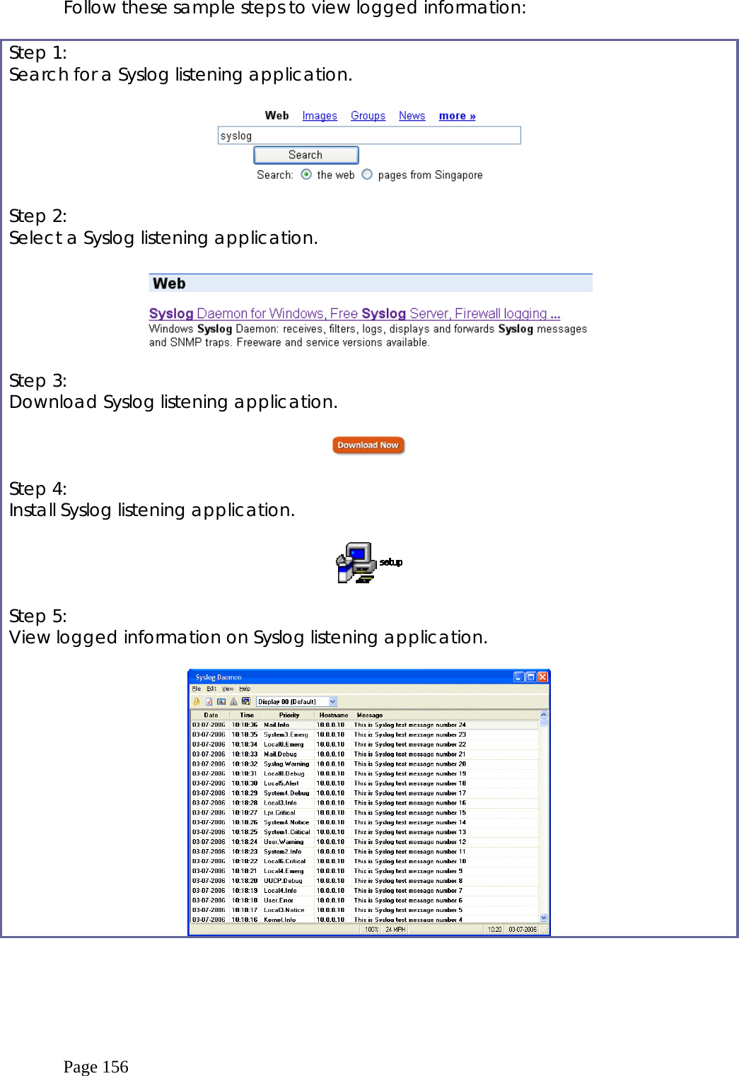
Compex Systems 08-WPE53G Wireless-G Network Access Point User Manual NETPASSAGE WPE53G
Compex Systems Pte Ltd Wireless-G Network Access Point NETPASSAGE WPE53G
UserManual.wiki
>
Compex Systems
>
08-WPE53G User Manual
>
manual part 2
Contents
1.
manual part 1
2.
manual part 2
manual part 2
Navigation menu
Upload a User Manual
Namespaces
Wiki Guide
HTML
PDF
Info
Views
User Manual
Discussion / Help
Navigation


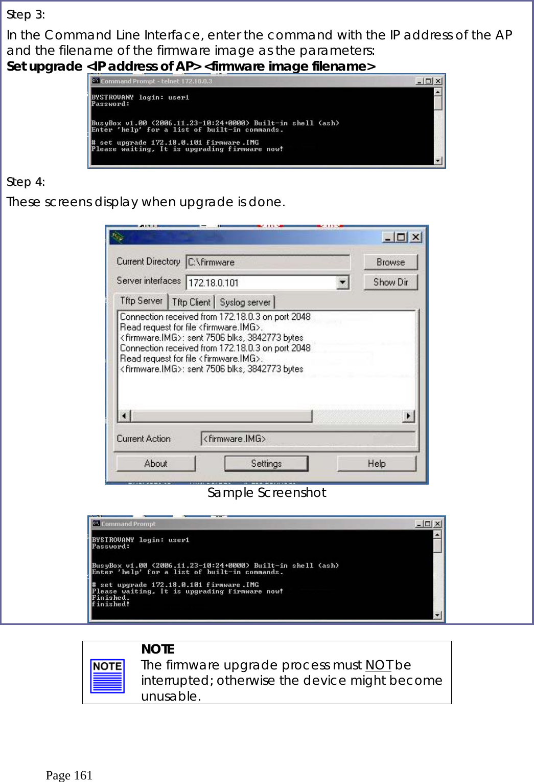
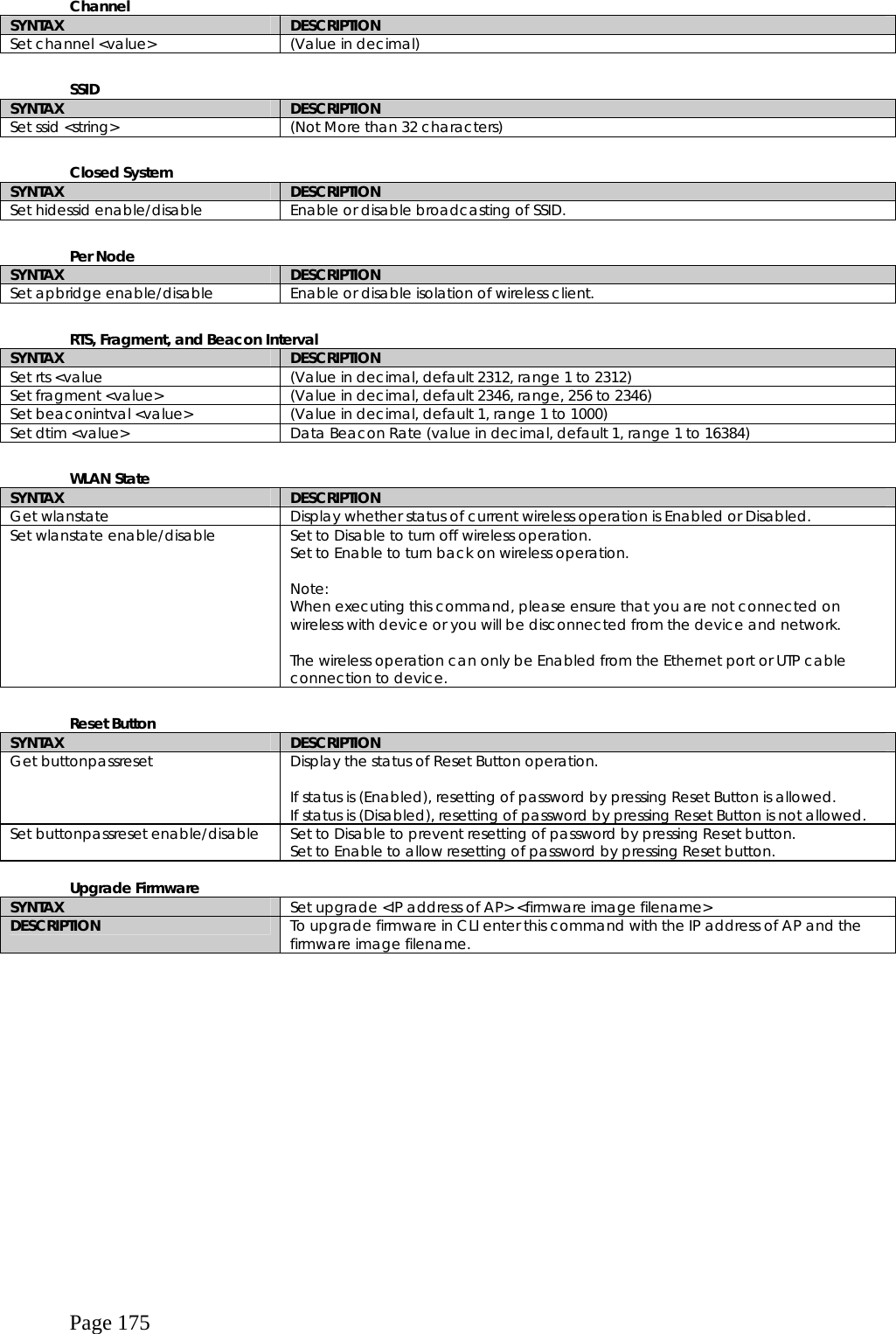
![Page 173 Wireless Mode SYNTAX DESCRIPTION Set wirelessmode <string> Supported strings are: auto, 11a, 11b, 11g, pureg, superg, supera Set autochannelselect Enable/disable Enable or disable smart channel select during power up. Set radio_off_eth_down enable/disable Enable or disable auto turn off radio when Ethernet port connection link is lost. WEP Key Must first set a key entry type, and then proceed to set the key index, size, and value. SYNTAX DESCRIPTION Set key <keyindex> <keysize> <keyvalue> Set keyentrymethod hex/ascii Set key <keyindex> default Set default key. Add or Delete User SYNTAX DESCRIPTION Set user < [-r|-w] > <password> username To add a user. Set user –d username To delete user. Country Code SYNTAX DESCRIPTION Set countrycode <iso.name> Set countrycode <2 letter string> List of countries: {0, "NA" }, {CTRY_ALBANIA, "AL" }, {CTRY_ALGERIA, "DZ" }, {CTRY_ARGENTINA, "AR" }, {CTRY_ARMENIA, "AM" }, {CTRY_AUSTRALIA, "AU" }, {CTRY_AUSTRIA, "AT" }, {CTRY_AZERBAIJAN, "AZ" }, {CTRY_BAHRAIN, "BH" }, {CTRY_BELARUS, "BY" }, {CTRY_BELGIUM, "BE" }, {CTRY_BELIZE, "BZ" }, {CTRY_BOLIVIA, "BO" }, {CTRY_BRAZIL, "BR" }, {CTRY_BRUNEI_DARUSSALAM, "BN" }, {CTRY_BULGARIA, "BG" }, {CTRY_CANADA, "CA" }, {CTRY_CHILE, "CL" }, {CTRY_CHINA, "CN" }, {CTRY_COLOMBIA, "CO" }, {CTRY_COSTA_RICA, "CR" }, {CTRY_CROATIA, "HR" }, {CTRY_CYPRUS, "CY" }, {CTRY_CZECH, "CZ" }, {CTRY_DENMARK, "DK" }, {CTRY_DOMINICAN_REPUBLIC, "DO" }, {CTRY_ECUADOR, "EC" }, {CTRY_EGYPT, "EG" }, {CTRY_EL_SALVADOR, "SV" }, {CTRY_ESTONIA, "EE" }, {CTRY_FINLAND, "FI" }, {CTRY_FRANCE, "FR" }, {CTRY_FRANCE2, "F2" }, {CTRY_GEORGIA, "GE" }, {CTRY_GERMANY, "DE" }, {CTRY_GREECE, "GR" }, {CTRY_GUATEMALA, "GT" }, {CTRY_HONDURAS, "HN" }, {CTRY_HONG_KONG, "HK" }, {CTRY_HUNGARY, "HU" }, {CTRY_ICELAND, "IS" }, {CTRY_INDIA, "IN" }, {CTRY_INDONESIA, "ID" }, {CTRY_IRAN, "IR" }, {CTRY_IRELAND, "IE" }, {CTRY_ISRAEL, "IL" },](https://usermanual.wiki/Compex-Systems/08-WPE53G.manual-part-2/User-Guide-926702-Page-77.png)