Compex Systems 08-WPE53G Wireless-G Network Access Point User Manual NETPASSAGE WPE53G
Compex Systems Pte Ltd Wireless-G Network Access Point NETPASSAGE WPE53G
Contents
- 1. manual part 1
- 2. manual part 2
manual part 2

Page 97
Step 3:
Click the A
Ad
dd
d button to create the rule for LAN user’s bandwidth
control.
Parameters Description
Rule Name You can set a name for the bandwidth
control rule.
Committed Rate
(kbit) Minimum bandwidth rate of throughput.
NOTE:
The sum of the Committed Rate of all the
rules should not exceed the total rate
available.
Ceiling Rate (kbit) Capped bandwidth rate of throughput.
Rule Type This defines whether the bandwidth control
rule works on downloads or uploads, and
whether it works by IP address or MAC
address.
IP/MAC Address IP address or MAC address for the
bandwidth control rule, corresponding to
whether the Rule Type is defined by IP
address or MAC address.
Step 4:
Click the A
Ad
dd
d
button.
Repeat Steps 1 to Step 3 to add new bandwidth rule.
Page 98
Perform Remote Management
(Available in Wireless Routing Client and Gateway modes)
You can use the access point web-based interface from the Internet to
manage your network remotely.
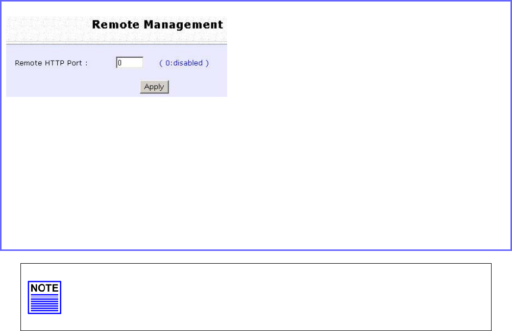
Setup Remote Management
Step 1:
Select R
Re
em
mo
ot
te
e
M
Ma
an
na
ag
ge
em
me
en
nt
t from the
C
CO
ON
NF
FI
IG
GU
UR
RA
AT
TI
IO
ON
N command menu.
Step 2:
To disable Remote Management, set R
Re
em
mo
ot
te
e
H
Ht
tt
tp
p
P
Po
or
rt
t to 0
To enable Remote Management, set R
Re
em
mo
ot
te
e
H
Ht
tt
tp
p
P
Po
or
rt
t to an unused port number. It
is recommended that you avoid using port number 80 as it is blocked by some ISPs.
In Gateway mode, R
Re
em
mo
ot
te
e
M
Ma
an
na
ag
ge
em
me
en
nt
t is enabled with Port 88 and the Ethernet
port becomes a WAN port. To continue using it, open the web manager using the
WAN IP with Port 88.
Example: For WAN IP 100.100.100.1 use http://100.100.100.1:88
NOTE
It is recommended that the default password is replaced with a new
password changed periodically to prevent unauthorized access.
Page 99
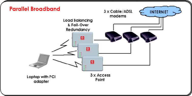
Use Parallel Broadband
(Available in Gateway mode)
Parallel Broadband provides scalable Internet bandwidth with Load
Balancing and Fail-Over Redundancy.
Load Balancing is provided by balancing the aggregate bandwidth of
multiple broadband connections across the traffic demands of your
private network. With Parallel Broadband, if a particular broadband
connection fails, the access point will use the remaining functional
broadband connections, thus providing Fail-Over Redundancy.
Implementing Parallel Broadband requires the installation of 2 or more
access points in the network, each connected to separate broadband
Internet service account. As there is no restriction to the type of
broadband Internet they are connected to, be it cable or ADSL, you
may thus have one access point connected to cable Internet, and
another to an ADSL line. The access points have to be operating in
Gateway mode with Parallel Broadband and set to the same ESSID.
Page 100
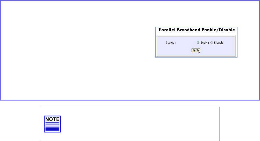
Enable Parallel Broadband
Begin by verifying that every access point in the network is properly
configured to connect to its individual broadband Internet account.
Secondly ensure that either:
• each access point is connected to an Ethernet port in the network
OR
• the access points are wired to each other.
Then all the access points has to have the DHCP server, followed by the
Parallel Broadband feature, enabled through the web-based
configuration. Please note that all the access points need to be
interconnected.
Step 1:
Select Parallel Broadband from the CONFIGURATION command menu.
Step 2:
Select Enable and click the Apply
button.
Step 3:
Repeat Step 1 and Step 2 for the rest of
the access points.
New users will then be assigned to the
access point with the smallest load,
ensuring that each access point has
approximately the same number of
users.
Important:
Implementing Parallel Broadband is redundant if
there is only 1 access point.
Page 101
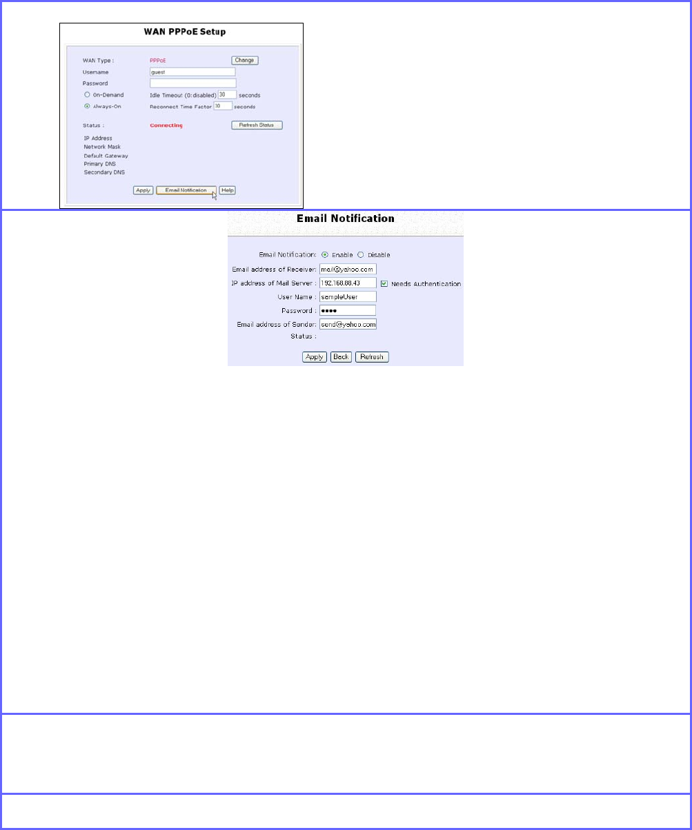
Setup Email Notification
This feature notifies you by email if there is a change in the WAN IP
address that was supplied to you.
Step 1:
Select W
WA
AN
N P
PP
PP
Po
oE
E
S
Se
et
tu
up
p or W
WA
AN
N
P
PP
PT
TP
P
S
Se
et
tu
up
p from the
C
CO
ON
NF
FI
IG
GU
UR
RA
AT
TI
IO
ON
N command menu.
Step 2:
Click on the E
Em
ma
ai
il
l
N
No
ot
ti
if
fi
ic
ca
at
ti
io
on
n
button.
Step 3:
Select to E
En
na
ab
bl
le
e Email Notification and enter the following details:
• Email address of Receiver:
Email address of the receiver to whom the message would be sent.
• IP address of Email Server:
IP address of the SMTP server through which the message will be sent.
It is recommended that you use your ISP’s SMTP server.
• User Name:
User Name for the specified email account.
This is necessary if authentication is required.
• Password:
Pass word for the specified email account.
This is necessary if authentication is required.
• Email address of Sender:
Email address to be displayed as the sender.
Step 4:
Specify whether the SMTP server N
Ne
ee
ed
ds
s
A
Au
ut
th
he
en
nt
ti
ic
ca
at
ti
io
on
n or not by setting the
checkbox accordingly. By default it is not selected.
Step 5:
Click on the A
Ap
pp
pl
ly
y button.
Page 102
Using Static Address Translation
(Available in Wireless Routing Client and Gateway modes)
If you use a notebook for work in the office, you most probably bring it
home to connect to the Internet as well. Since it is most likely that your
office network and home network broadband-sharing network subnets
are configured differently, you would have the hassle of reconfiguring
your TCP/IP settings every time you use the notebook in a different
place. Static Address Translation allows you to bypass this hassle.
With SAT, if you try to access the Internet on your notebook from home
but with your office TCP/IP settings, the notebook will try to contact the
IP address of your office gateway to the Internet. When the access
point finds that the notebook is trying to contact a device lying on a
different subnet from that of the home network, it would inform the
notebook that the gateway to the Internet is in fact the access point
itself. From then the notebook would contact the access point for
access to the Internet without any change to the TCP/IP settings.
NOTE
For SAT to function properly:
1. The IP address of the notebook should belong to a different
subnet from the LAN IP address of your access point.
2. The <Default Gateway> in the TCP/IP settings of your
notebook should NOT be left blank.
Step 1:
Select S
St
ta
at
ti
ic
c
A
Ad
dd
dr
re
es
ss
s
T
Tr
ra
an
ns
sl
la
at
ti
io
on
n from the H
Ho
om
me
e
U
Us
se
er
r
F
Fe
ea
at
tu
ur
re
es
s
command menu.
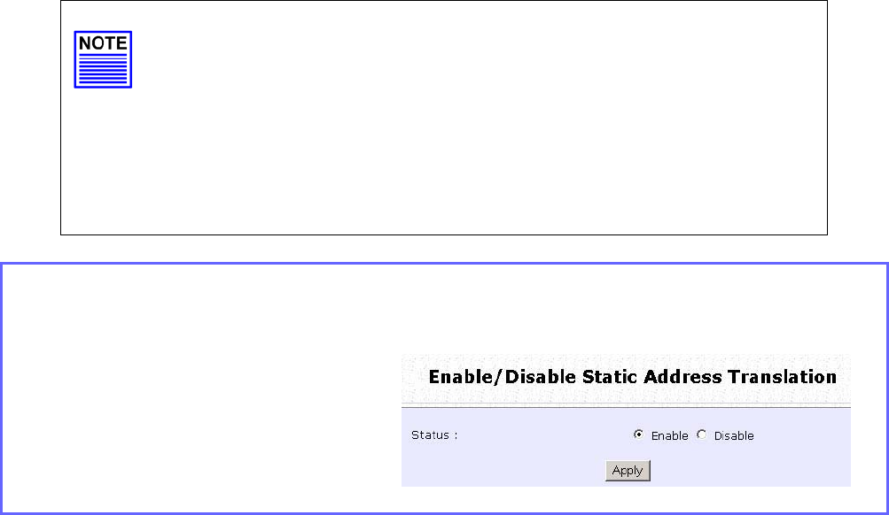
Step 2:
Select whether to E
En
na
ab
bl
le
e or
D
Di
is
sa
ab
bl
le
e SAT, and click the
A
Ap
pp
pl
ly
y button.
SAT is disabled by default.
Page 103
Use DNS Redirection
(Available in Wireless Routing Client and Gateway modes)
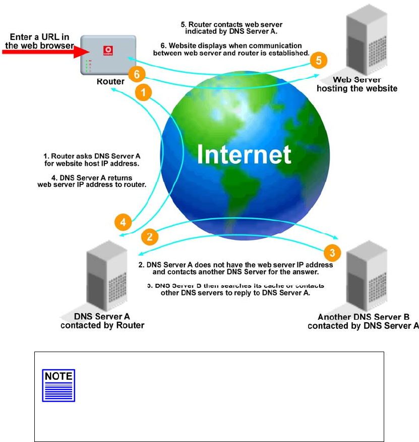
When you enter a URL into your Internet browser, it requests for a name-
to-IP address translation from the Domain Name System (DNS) servers
to locate the web server hosting the desired website. The DNS server
searches its local cache for the answer, and if found, returns this
cached IP address. Otherwise, it contacts other DNS servers until the
query is answered.
With DNS Redirection, DNS requests from the LAN clients are processed
by the access point. It contacts the DNS server allocated by your ISP to
resolve these DNS requests unless you have already specified a default
DNS server in the access point LAN Setup. This default DNS server
overrides the one defined in the TCP/IP settings of the LAN clients,
allowing the access point to direct DNS requests from the LAN to a
local or to a closer DNS server that it is aware of, thus improving the
response time.
DNS Redirection also provides more control to the network
administrator. In the event that there is a change in DNS servers, he can
simply indicate the actual DNS server IP address an the access point
LAN Setup and enable DNS Redirection, without having to reconfigure
the DNS settings of every LAN client.
Page 104
NOTE
An entry for the DNS Server field in the PC TCP/IP
Properties is required for Internet access.
If the exact DNS IP address is unavailable, simple
key in any valid IP address, for example:
10.10.10.10

Page 105
Enable or Disable DNS Redirection
Step 1:
Select D
DN
NS
S
R
Re
ed
di
ir
re
ec
ct
ti
io
on
n from the H
Ho
om
me
e
U
Us
se
er
r
F
Fe
ea
at
tu
ur
re
es
s
command menu.
Step 2:
Select to E
En
na
ab
bl
le
e or D
Di
is
sa
ab
bl
le
e
DNS Redirection.
Step 3:
Click the A
Ap
pp
pl
ly
y button.

Page 106
Dynamic DNS Setup
With Dynamic IP Internet connection, keeping track of your public IP
address for Internet communication is complicated as it is changed
regularly by the ISP. If you are doing some web hosting on your
computer, Internet users will have to keep up with the changing IP
address to access your computer.
When you sign up for an account with a Dynamic Domain Name
Service (DDNS) provider, it will register your permanent domain name,
for example: MyName.Domain.com You can configure the access
point to automatically contact your DDNS provider whenever it detects
a change in its public IP address. The access point will then log on to
update your account with its latest public IP address.
If a user enters your address: MyName.Domain.com into their web
browser, this request would go to the DDNS provider which will then
redirect the request to your computer, regardless of the IP address it is
currently assigned by your ISP.
To enable/disable Dynamic DNS Setup
Step 1:
Select D
Dy
yn
na
am
mi
ic
c
D
DN
NS
S
S
Se
et
tu
up
p from the H
Ho
om
me
e
U
Us
se
er
r
F
Fe
ea
at
tu
ur
re
es
s
command menu.
Step 2:
Select to E
En
na
ab
bl
le
e or D
Di
is
sa
ab
bl
le
e Dynamic
DNS.
Dynamic DNS is disabled by default.
Click the A
Ap
pp
pl
ly
y button.
Page 107
To manage Dynamic DNS List
Step 1:
Select D
Dy
yn
na
am
mi
ic
c
D
DN
NS
S
S
Se
et
tu
up
p from the H
Ho
om
me
e
U
Us
se
er
r
F
Fe
ea
at
tu
ur
re
es
s
command menu.
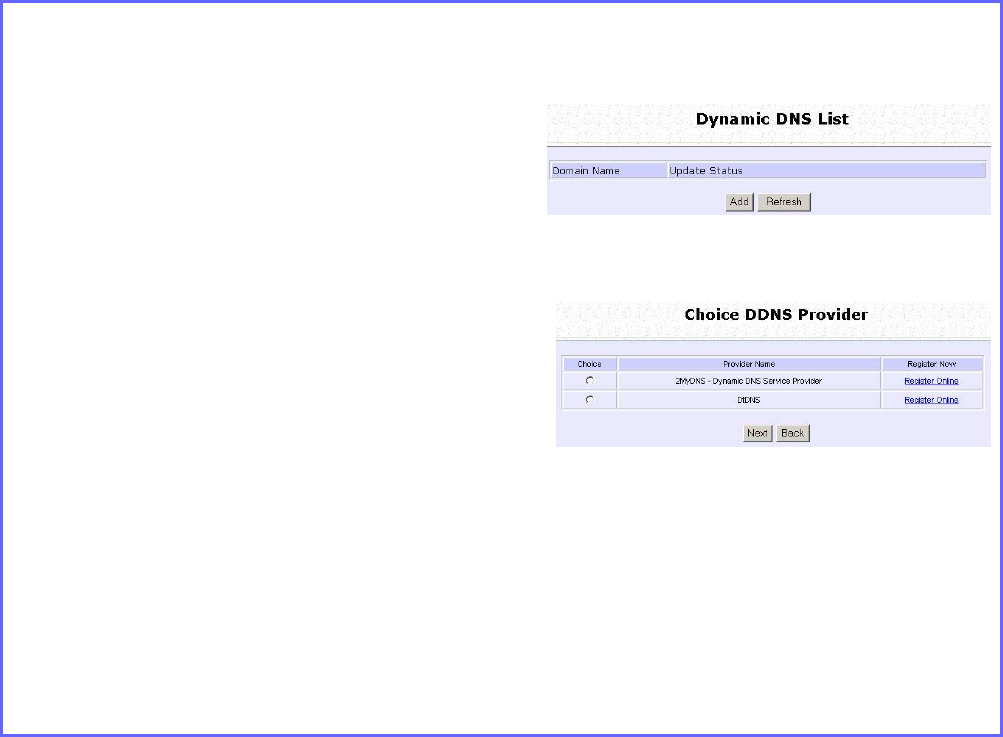
Step 2:
If you have created a list earlier,
click on the R
Re
ef
fr
re
es
sh
h button to
update the list.
Step 3:
To add a new Dynamic DNS,
click on the Add button.
The C
Ch
ho
oi
ic
ce
e
D
DD
DN
NS
S
P
Pr
ro
ov
vi
id
de
er
r page
appears.
There are two default providers
that you can use.
The parameters are explained
below:
• Choice:
Indicates your preferred DDNS provider.
• Provider Name:
Name of your preferred DDNS provider.
• Register Now:
Allows you to go to the website of your preferred DDNS provider where you can
register your account.
Page 108
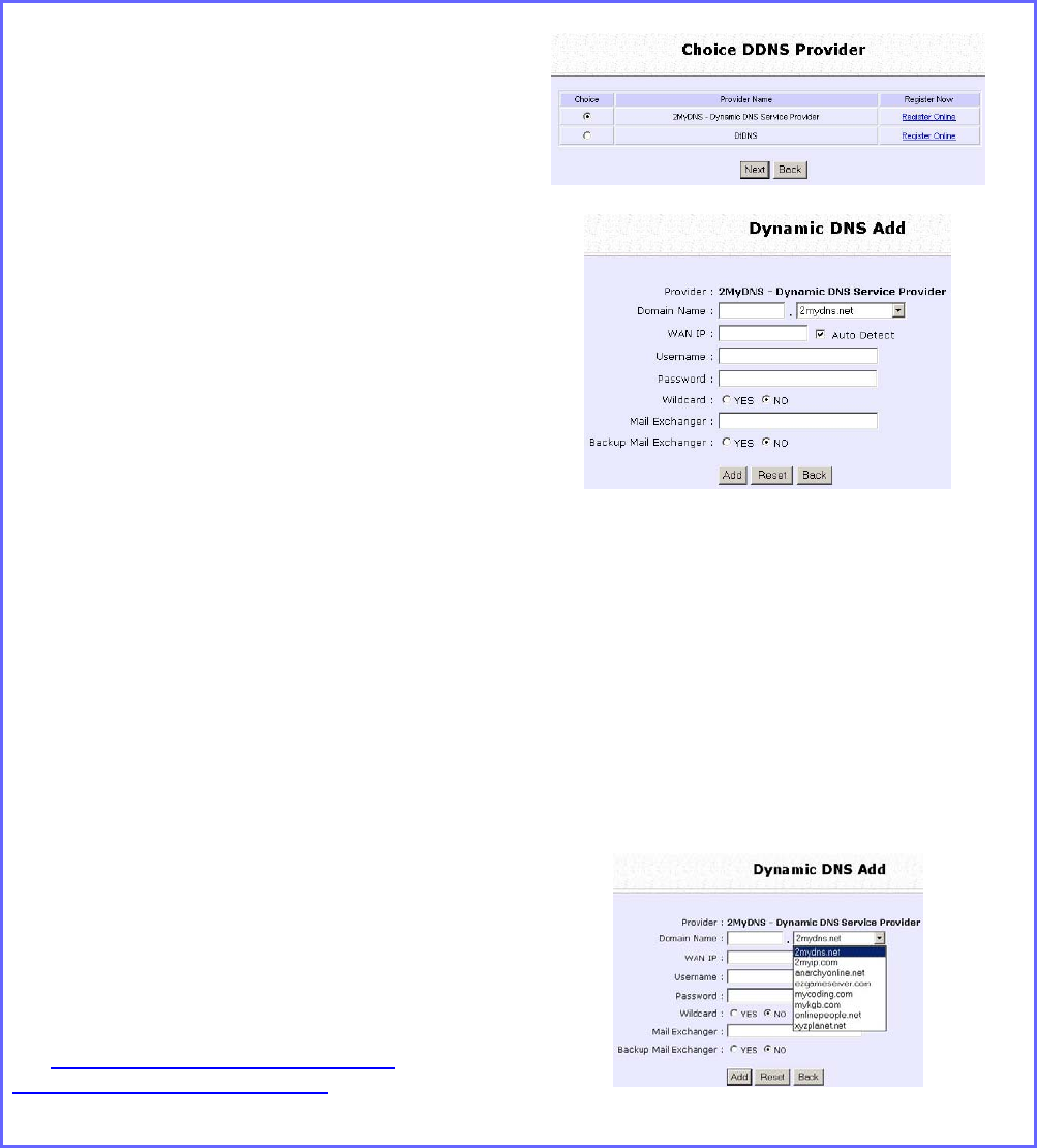
2 DDNS providers are predefined for you. You need to be connected
to the Internet to register your DDNS account.
Select 2MyDNS – Dynamic DNS Service Provider as DDNS Service
Provider:
Step 1:
Under the C
Ch
ho
oi
ic
ce
e column in the
C
Ch
ho
oi
ic
ce
e
D
DD
DN
NS
S
P
Pr
ro
ov
vi
id
de
er
r list, check the
radio button next to the 2
2M
My
yD
DN
NS
S
–
–
D
DN
NS
S
S
Se
er
rv
vi
ic
ce
e
P
Pr
ro
ov
vi
id
de
er
r entry.
Click on the N
Ne
ex
xt
t button.
Step 2:
Enter your D
Do
om
ma
ai
in
n
N
Na
am
me
e.
Step 3:
The A
Au
ut
to
o
D
De
et
te
ec
ct
t checkbox is
selected by default.
The
W
WA
AN
N
I
IP
P
field is empty by default.
These default settings should be used
if dynamic WAN IP connection is
used.
If your ISP connection uses dynamic
WAN IP:
Select the A
Au
ut
to
o
D
De
et
te
ec
ct
t
checkbox to
let the DDNS server learn your current
WAN IP address.
Enter your DDNS account U
Us
se
er
rn
na
am
me
e
and P
Pa
as
ss
sw
wo
or
rd
d.
If your ISP connection uses a fixed
WAN IP:
Enter the IP address in the W
WA
AN
N
I
IP
P
field.
Deselect the A
Au
ut
to
o
D
De
et
te
ec
ct
t
checkbox.
The access point will update the
DDNS server with the specified WAN
IP.
Step 4: Optional
Your hostname will be allowed
multiple identities if wildcard is
enabled.
For example, if you register:
m
my
yd
do
om
ma
ai
in
n.
.2
2m
my
yd
dn
ns
s.
.n
ne
et
t, users looking
for www.mydomain.2mydns.net or
ftp.mydomain.2mydns.net can still
reach your hostname.
Page 109
Step 5: Optional
In the Mail Exchanger field, enter the
Static WAN IP address of the mail
server configured to handle email for
your domain.
Select B
Ba
ac
ck
ku
up
p
M
Ma
ai
il
l
E
Ex
xc
ch
ha
an
ng
ge
er
r to
enable this service.
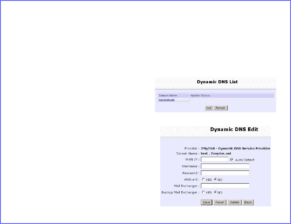
Step 6:
Click on the Add button.
The new domain is added to the
Dynamic DNS list table. It will appear
as a hyperlink that you can click to
go back to the Dynamic DNS Edit
page.
Step 7:
From the Dynamic DNS Edit page
you can update or reset the
parameters, or delete the domain
name.
Page 110
Select DtDNS as DDNS Service Provider:
Step 1:
Under the C
Ch
ho
oi
ic
ce
e column in the
C
Ch
ho
oi
ic
ce
e
D
DD
DN
NS
S
P
Pr
ro
ov
vi
id
de
er
r list, check the
radio button next to the D
Dt
tD
DN
NS
S entry.
Click on the N
Ne
ex
xt
t button.
Step 2:
Enter your D
Do
om
ma
ai
in
n
N
Na
am
me
e.
Step 3:
The A
Au
ut
to
o
D
De
et
te
ec
ct
t checkbox is selected
by default.
The
W
WA
AN
N
I
IP
P
field is empty by default.
These default settings should be used if
dynamic WAN IP connection is used.
If your ISP connection uses dynamic
WAN IP:
Select the A
Au
ut
to
o
D
De
et
te
ec
ct
t
checkbox to let
the DtDNS server learn your current
WAN IP address.
Enter your DtDNS account U
Us
se
er
rn
na
am
me
e
and P
Pa
as
ss
sw
wo
or
rd
d.
If your ISP connection uses a fixed WAN
IP:
Enter the IP address in the W
WA
AN
N
I
IP
P
field.
Deselect the A
Au
ut
to
o
D
De
et
te
ec
ct
t
checkbox.
The access point will update the DtDNS
server with the specified WAN IP.
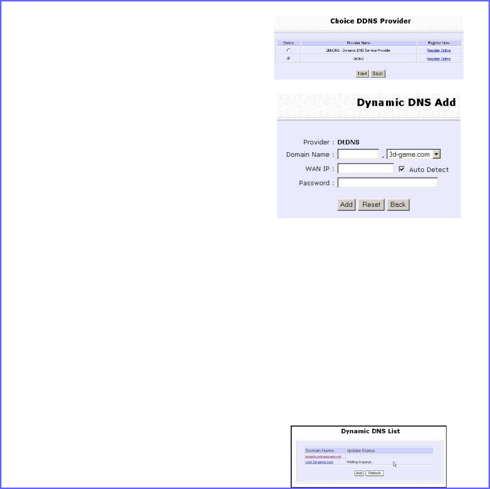
Step 4:
Then click on the
A
Ad
dd
d button.
Step 5:
While the new domain name
is being
added to the list, the message ‘Waiting
in queue…” will be displayed under the
U
Up
pd
da
at
te
e S
St
ta
at
tu
us
s column of the D
Dy
yn
na
am
mi
ic
c
D
DN
NS
S
L
Li
is
st
t table.
Page 111
Use the Wireless Extended Features
Setup WDS2
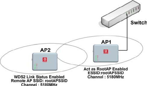
WDS2 (Wireless Distributed System 2) links up access points to create a
wider network in which mobile users can roam while still staying
connected to available network resources. The wireless client and root
access point has to be set up with the same channel frequency. This
allows them to connect even when the link is lost, as the channel
frequency setting is preserved.
In this example, there are 2 access points: Access Point 1 and Access
Point 2, with Access Point 1 as the root access point.
Page 112
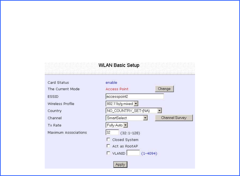
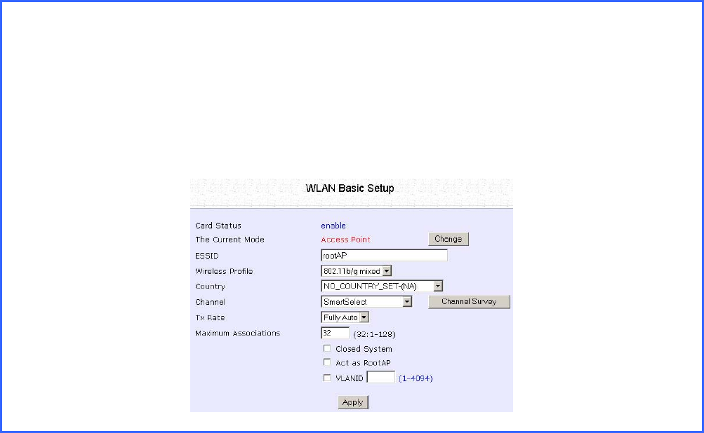
Follow these steps to change the setup the root access point.
S
Se
et
tu
up
p
a
ac
cc
ce
es
ss
s
p
po
oi
in
nt
t
1
1:
:
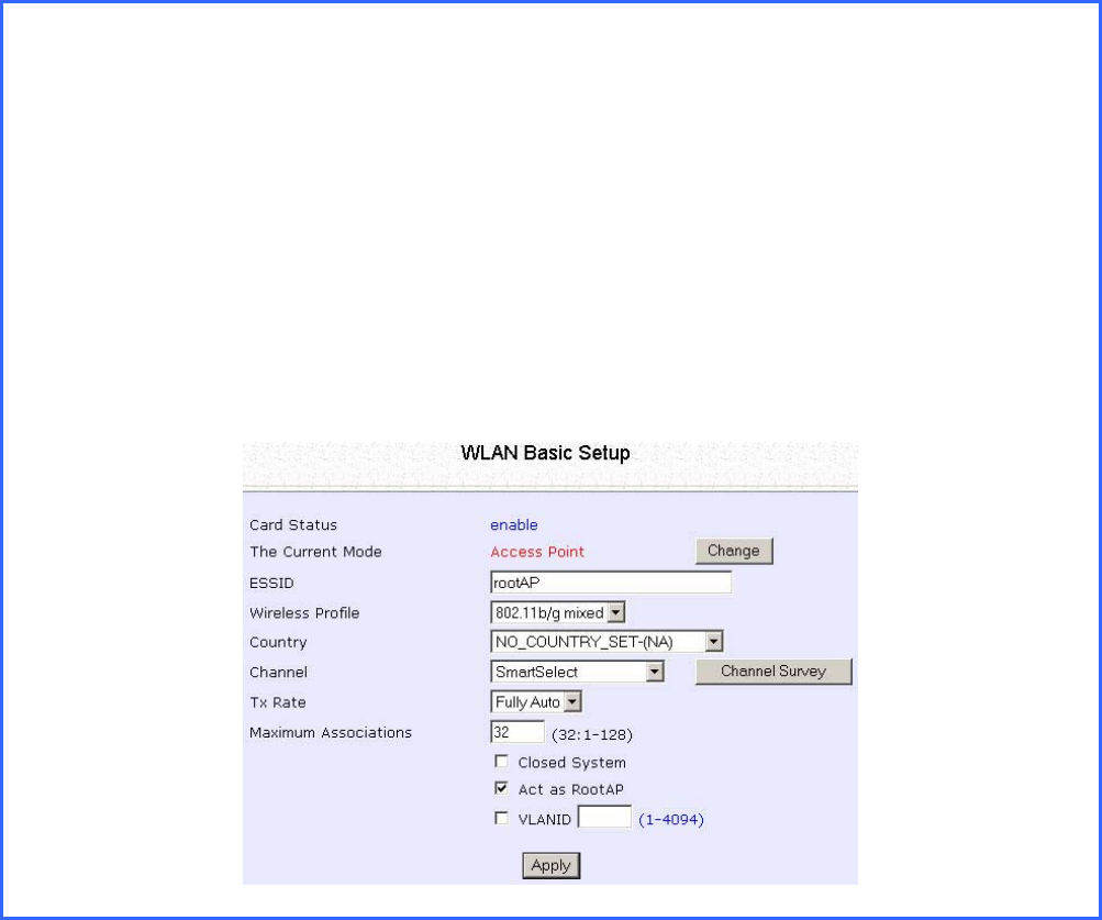
Click on W
WL
LA
AN
N
S
Se
et
tu
up
p from the C
CO
ON
NF
FI
IG
GU
UR
RA
AT
TI
IO
ON
N menu. You will see the sub-menus
expanded under W
WL
LA
AN
N
S
Se
et
tu
up
p. Click on B
Ba
as
si
ic
c.
Ensure that T
Th
he
e
C
Cu
ur
rr
re
en
nt
t
M
Mo
od
de
e
is set to A
Ac
cc
ce
es
ss
s
P
Po
oi
in
nt
t.
To change T
Th
he
e
C
Cu
ur
rr
re
en
nt
t
M
Mo
od
de
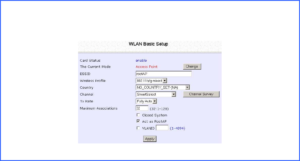
e, please refer to: Common Configuration – WLAN
Setup - To Configure the Basic Setup of the Wireless Mode.
Select A
Ac
ct
t
a
as
s
R
Ro
oo
ot
tA
AP
P.
Select the C
Ch
ha
an
nn
ne
el
l
common to both access point 1 and access point 2.
Page 113
Follow these settings to setup access point 2.
S
Se
et
tu
up
p
a
ac
cc
ce
es
ss
s
p
po
oi
in
nt
t
2
2:
:
Click on W
WL
LA
AN
N
S
Se
et
tu
up
p from the C
CO
ON
NF
FI
IG
GU
UR
RA
AT
TI
IO
ON
N menu. You will see the sub-menus
expanded under W
WL
LA
AN
N
S
Se
et
tu
up
p. Click on B
Ba
as
si
ic
c.
Select the C
Ch
ha
an
nn
ne
el
l
common to both access point 1 and access point 2.
Page 114
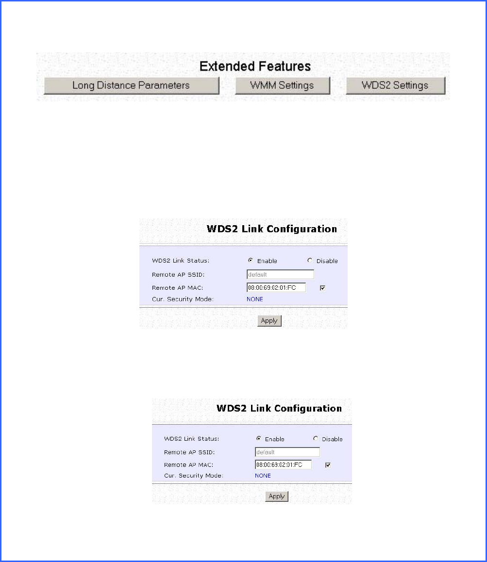
C
Co
on
nf
fi
ig
gu
ur
re
e
W
WD
DS
S2
2
l
li
in
nk
k:
:
Click on W
WL
LA
AN
N
S
Se
et
tu
up
p from the C
CO
ON
NF
FI
IG
GU
UR
RA
AT
TI
IO
ON
N menu. You will see the sub-menus
expanded under W
WL
LA
AN
N
S
Se
et
tu
up
p. Click on A
Ad
dv
va
an
nc
ce
ed
d.
Under E
Ex
xt
te
en
nd
de
ed
d
F
Fe
ea
at
tu
ur
re
es
s, click on the W
WD
DS
S2
2
S
Se
et
tt
ti
in
ng
gs
s button.
Set W
WD
DS
S2
2
L
Li
in
nk
k
S
St
ta
at
tu
us
s to E
En
na
ab
bl
le
e.
Options for configuring WDS2 link:
• By Remote AP MAC – Enter the Remote AP MAC
OR
• By Remote AP SSID – Uncheck the Remote AP MAC checkbox and enter the
Remote AP SSID.
C
Cl
li
ic
ck
k
Apply.
.
Page 115
Set Virtual AP (Multiple SSID)
Virtual AP implements mSSID (Multi-SSID) whereby a single wireless card
can be setup with up to 16 virtual AP connections with different SSIDs or
BSSID (Basic Service Set Identifier) and security modes.
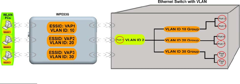
Virtual AP delivers multiple services by VLAN segmentation: making the
network think there are many SSIDs available and channeling each
connection through different VLANs to the respective virtual network
segments on the Ethernet network.
How it Works
When WLAN PC 1 connects to VAP 1 its packets are channeled to
VLAN 10 group where only services connected to Port 2 and Port 3 are
available to this wireless connection.
It is similar for WLAN PC 2 and WLAN PC 3. Although they connect to
the same radio card as WLAN PC 1, WLAN PC 2 can only access the
services available at Port 6 and Port 7 and WLAN PC 3 can only access
the services available at Port 10 and Port 11.
For more information on Virtual AP (Multiple SSID) please refer to
Appendix: Virtual AP (Multiple SSID) FAQ.
Page 116
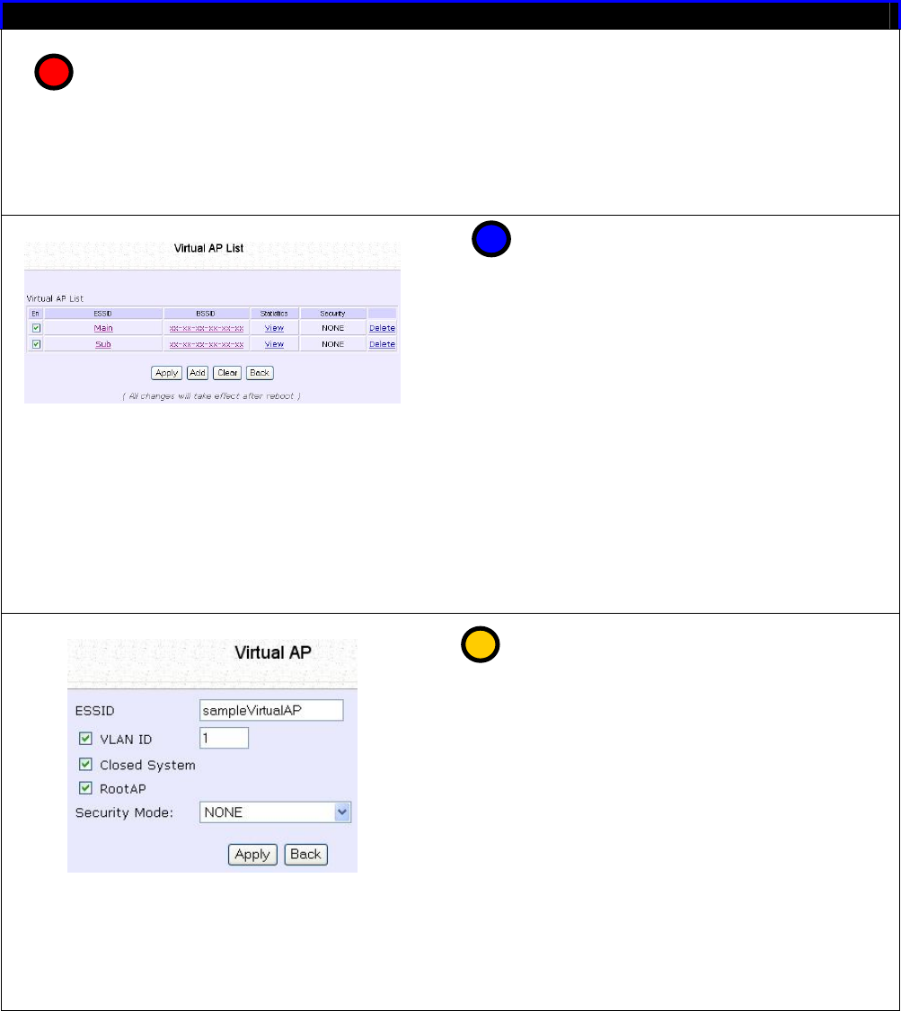
Follow these steps to setup Virtual AP.
Virtual AP
Click on WLAN Setup from the
CONFIGURATION menu.
Select Virtual AP.
Virtual AP List page displays.
• Click Apply to register changes.
• Click Clear to clear Virtual AP List.
• Click Back to return to WLAN Basic
Setup page.
• Select the Delete option beside
any Virtual APs you wish to delete.
Click Add to goto add Virtual AP page.
1. Enter ESSID name.
2. Settings:
• VLAN ID
• Closed System
• RootAP
3. Select Security Mode
4. Click Apply to make changes or
click Back to return to Virtual AP
List page.
1
2
3

Page 117
Set Preferred APs
(Available in Client Mode)
When there is more than one AP with the same SSID, the Preferred APs
function allows you define the MAC address of the APs in order of
preference.
The MAC address at the top of the Preferred APs list has the highest
connection preference, and the MAC address at the bottom has the
lowest connection preference.
Follow these steps to specify your preferred APs.
Preferred APs
1. Click on WLAN Setup from the
CONFIGURATION menu.
2. Select Preferred APs.
1. Enter the MAC addresses of
the preferred APs.
2. Click Apply to effect the
settings.
1
2
Page 118
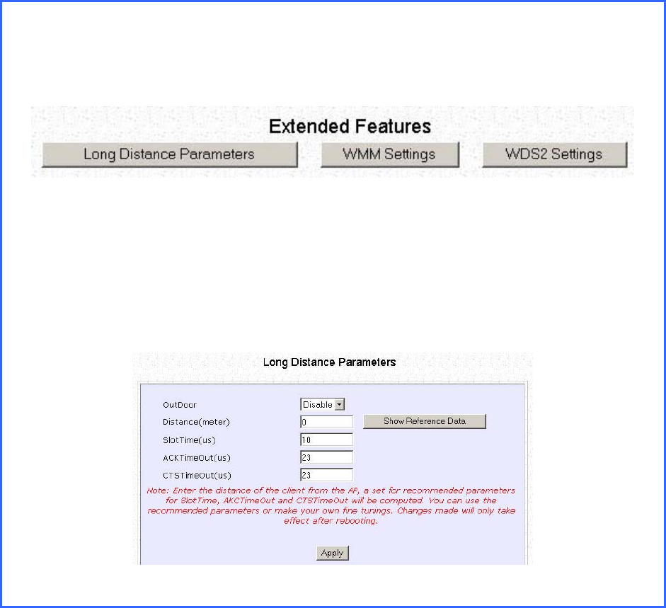
Get Long Distance Parameters
The access point can calculate and display suggested values for
certain parameters to use to ensure that efficient wireless
communication between physically distant access points.
Select A
Ad
dv
va
an
nc
ce
ed
d from W
WL
LA
AN
N
S
Se
et
tu
up
p under C
Co
on
nf
fi
ig
gu
ur
ra
at
ti
io
on
n.
Click on the L
Lo
on
ng
g
D
Di
is
st
ta
an
nc
ce
e
P
Pa
ar
ra
am
me
et
te
er
rs
s button under the E
Ex
xt
te
en
nd
de
ed
d
F
Fe
ea
at
tu
ur
re
es
s
section.
Select to E
En
na
ab
bl
le
e the O
Ou
ut
td
do
oo
or
r function.
Page 119
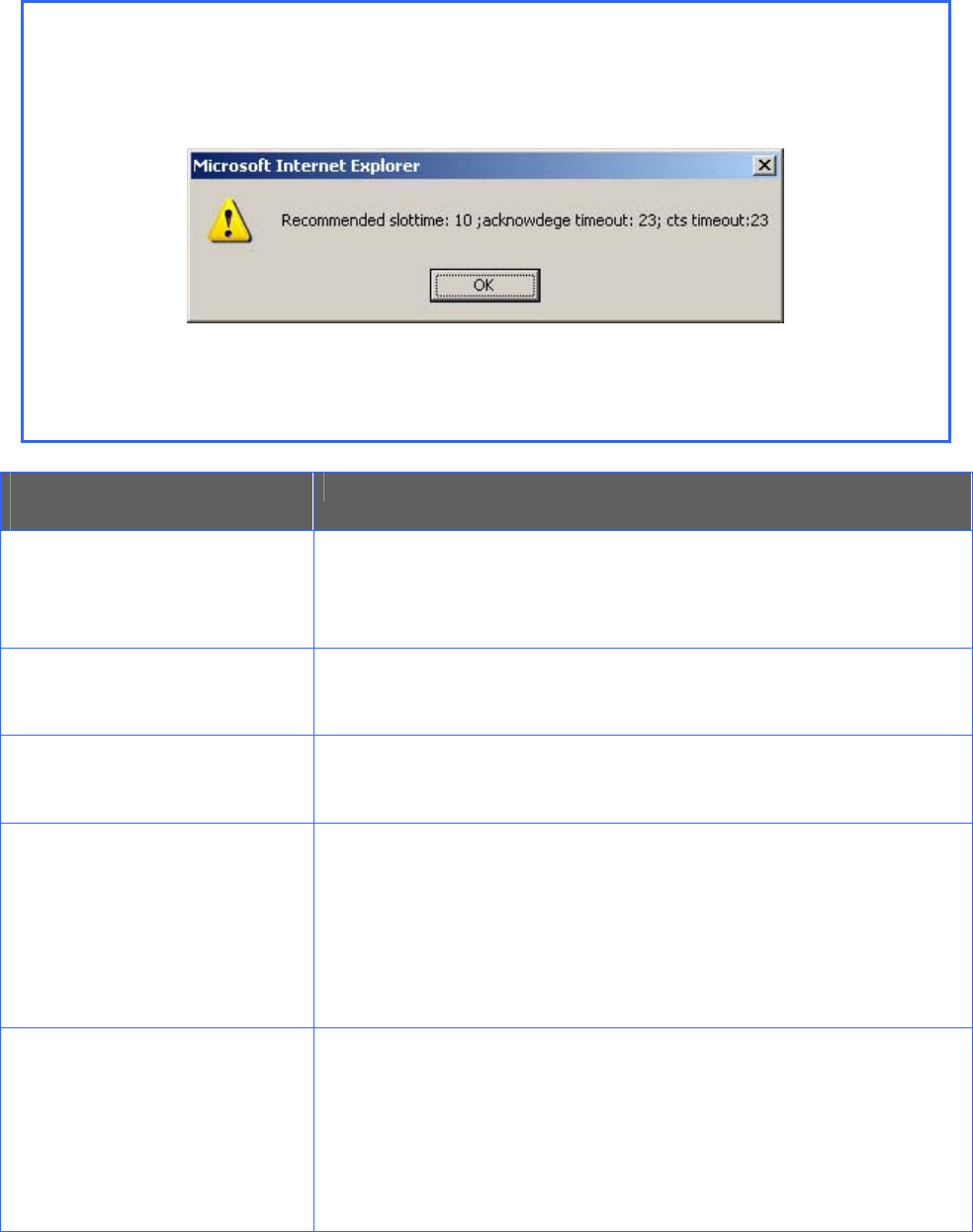
The access point can automatically calculate the values of the parameters to
input based on the distance between your access point and the other wireless
device. Enter the distance in meters and click on the S
Sh
ho
ow
w
R
Re
ef
fe
er
re
en
nc
ce
e
D
Da
at
ta
a
button.
You can enter the parameters based on the recommended values in the pop-
up window, click on the A
Ap
pp
pl
ly
y button to update the changes.
Long Distance
Parameters Description
Outdoor If set to Enable, the Outdoor parameters will be
configured for outdoor communication over short or
long distances as specified, it is disabled by default.
Distance Determines the distance between your access point
and the remote access point in meters.
Slot Time The amount of time is divided and each unit of time is
called one slot time.
ACK Timeout Determines the timeout allowed for the sending client
to receive the acknowledgment response from the
receiving client. If no acknowledgment packet is
received within this period, the sender will assume the
receiver has not received the packet and will attempt
to resend.
CTS Timeout Clear-to-Send Timeout is the time the wireless sender
will wait for a CTS packet signaling that the channel is
idle and it can start data transmission. If no CTS packet
is received within this period, the sender will assume the
channel is busy and will wait before trying to send
again.
Page 120
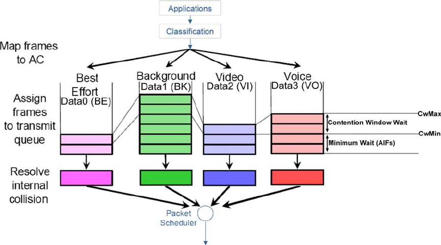
Set Wireless Multimedia
Wireless Multimedia (WMM) is a QoS (Quality of Service) standard in
IEEE802.11E that we have adopted to improve and support the user
experience for multimedia, video, and voice applications by prioritizing
data traffic. QoS can be realized through 4 different Access Categories
(AC). Each AC type consists of an independent transmit queue, and a
channel access function with its own parameters.
Page 121
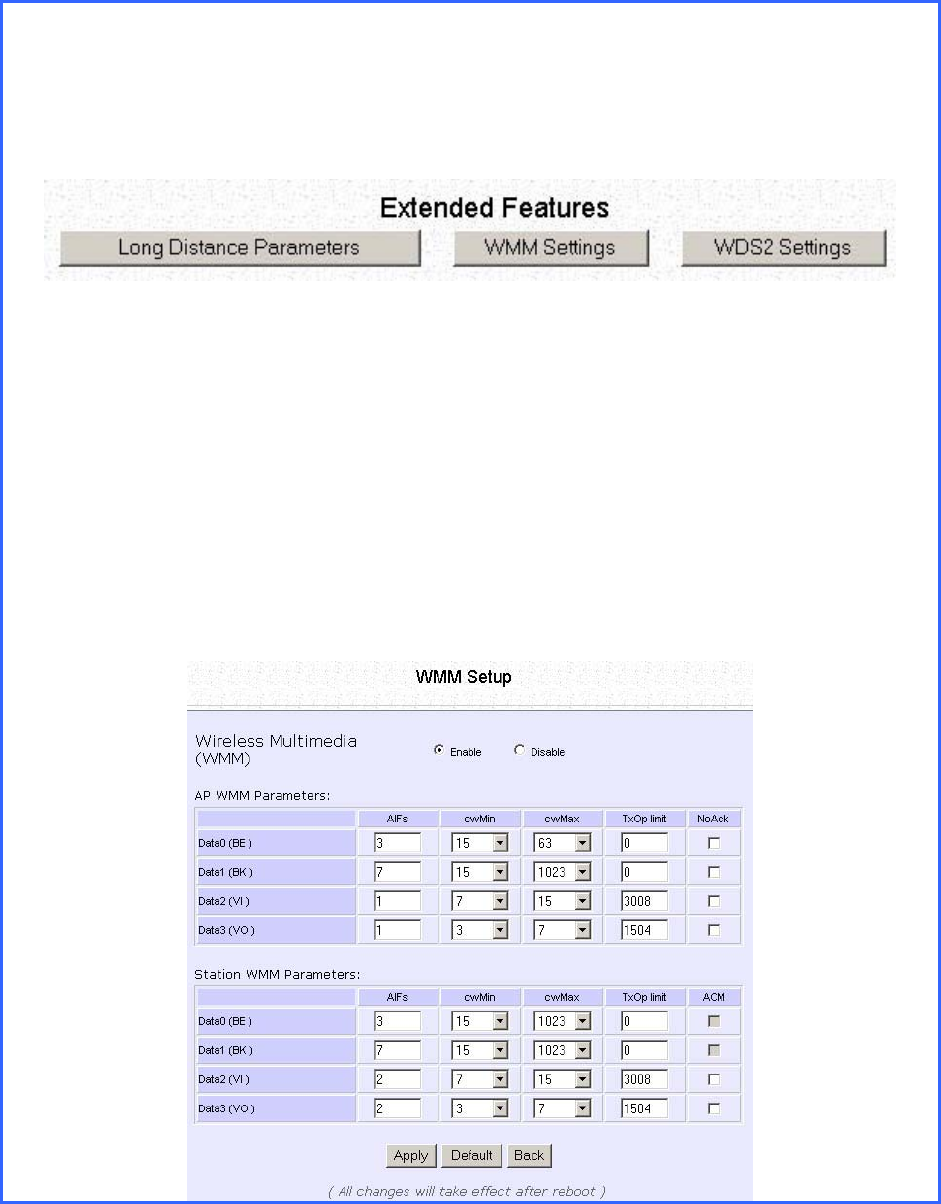
Follow these steps to change the setup Wireless Multimedia on your
access point.
Step 1:
1. Click on WLAN Setup from the CONFIGURATION menu.
2. Select Advanced.
Step 2:
Click on the WMM Settings button.
Step 3:
Select to Enable Wireless Multimedia (WMM)
Enter the desired WMM parameters. Using the default parameters is
recommended.
Click Apply to apply the WMM settings, click Default to reset all parameters to
default, or click Back to discard any changes and return to WLAN Basic Setup
page.

Page 122
WMM Parameters (for advanced users)
AIFs (Arbitrary
Inter-Frame
Space)
Arbitrary Inter-Frame Space is the minimum wait time interval
between the wireless medium becoming idle and the start of
transmission of a frame over the network.
Cwmin
(Contention
Window
Minimum)
Contention Window Minimum is the minimum random wait time
drawn from this interval or window for the backoff mechanism on
the network.
CwMax
(Contention
Window
Maximum)
Contention Window Maximum is the maximum random wait time
drawn from this interval or window for the backoff mechanism on
the network.
TxOp limit
(Transmit
Opportunity
Limit)
Transmit Opportunity limit specifies the minimum duration that an
end-user device can transmit data traffic after obtaining a transmit
opportunity. TxOp limit can be used to give data traffic longer and
shorter access.
NoAck (No
Acknowledge
ment)
No Acknowledgement provides control of the reliability of traffic
flow. Usually an acknowledge packet is returned for every packet
received, increasing traffic load and decreasing performance.
Enabling No Acknowledgement cancels the acknowledgement.
This is useful for data traffic where speed of transmission is important.
ACM
(Admission
Control
Mandatory)
Admission Control Mandatory enables WMM on the radio interface.
When ACM is enabled, associated clients must complete the WMM
admission control procedure before access.
BE (Best Effort) Parameters for Data0 Best Effort.
Best Effort data traffic has no prioritization and applications equally
share available bandwidth.
BK
(Background) Parameters for Data1 Background.
Background data traffic is de-prioritized and is mostly for backup
applications, or background transfers like backup applications or
background transfers like bulk copies that do not impact ongoing
traffic like Internet downloads.
VI (Video) Parameters for video data traffic.
VO (Voice) Parameters for voice data traffic.
Page 123
Setup Point-to-Point & Point-to-
MultiPoint Connection
You can implement Point-to-Point connection by simply setting one
access point as RootAP in Access Point mode and setting the other
access points to Transparent Client mode.
You can set a root access point and a transparent client to allow point-
to-point communication between different buildings and enable you
to bridge wireless clients that are kilometres apart while unifying the
networks. Or you can set a root access point and multiple transparent
clients to allow point-to-multiple-point communication between the
access point located at a facility and several other access points
installed in any direction from that facility.
Follow these steps to setup RootAP
R
Ro
oo
ot
tA
AP
P
S
St
te
ep
p
1
1:
:
Click on W
WL
LA
AN
N
S
Se
et
tu
up
p from the C
CO
ON
NF
FI
IG
GU
UR
RA
AT
TI
IO
ON
N menu. You will see the sub-menus
expanded under W
WL
LA
AN
N
S
Se
et
tu
up
p. Click on B
Ba
as
si
ic
c.
Ensure that T
Th
he
e
C
Cu
ur
rr
re
en
nt
t
M
Mo
od
de
e
is set to A
Ac
cc
ce
es
ss
s
P
Po
oi
in
nt
t.
To change T
Th
he
e
C
Cu
ur
rr
re
en
nt
t
M
Mo
od
de
e, please refer to: Common Configuration – WLAN
Setup - To Configure the Basic Setup of the Wireless Mode.
Page 124
R
Ro
oo
ot
tA
AP
P
S
St
te
ep
p
2
2:
:
Select A
Ac
ct
t
a
as
s
R
Ro
oo
ot
tA
AP
P, click on the A
Ap
pp
pl
ly
y button and reboot your device to let your
changes take effect.
Page 125
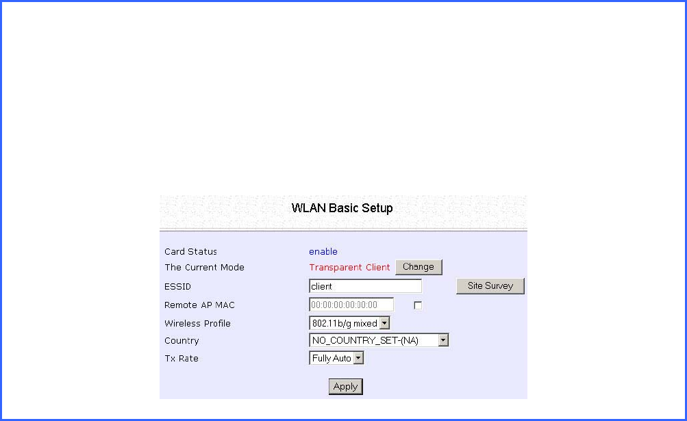
Follow these steps to setup Transparent Client/s.
T
Tr
ra
an
ns
sp
pa
ar
re
en
nt
t
C
Cl
li
ie
en
nt
t
S
St
te
ep
p
1
1:
:
Click on W
WL
LA
AN
N
S
Se
et
tu
up
p from the C
CO
ON
NF
FI
IG
GU
UR
RA
AT
TI
IO
ON
N menu. You will see the sub-menus
expanded under W
WL
LA
AN
N
S
Se
et
tu
up
p. Click on B
Ba
as
si
ic
c.
Ensure that T
Th
he
e
C
Cu
ur
rr
re
en
nt
t
M
Mo
od
de
e
is set to T
Tr
ra
an
ns
sp
pa
ar
re
en
nt
t
C
Cl
li
ie
en
nt
t.
To change T
Th
he
e
C
Cu
ur
rr
re
en
nt
t
M
Mo
od
de
e, please refer to: Common Configuration – WLAN
Setup - To Configure the Basic Setup of the Wireless Mode.
Page 126
T
Tr
ra
an
ns
sp
pa
ar
re
en
nt
t
C
Cl
li
ie
en
nt
t
S
St
te
ep
p
2
2:
:
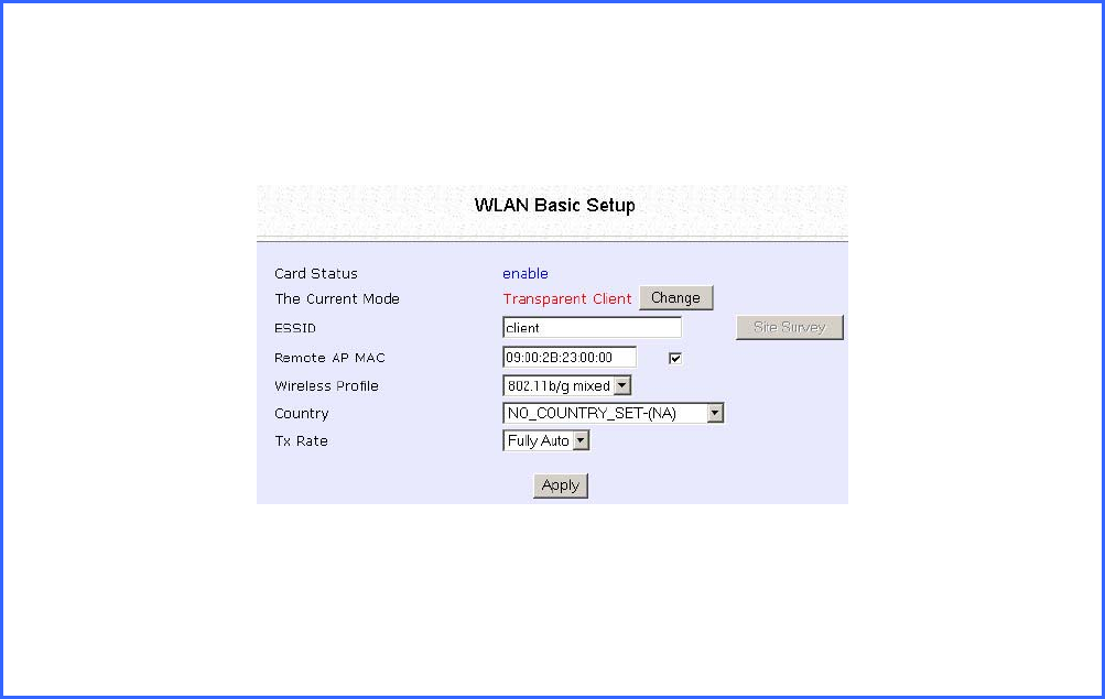
Select the R
Re
em
mo
ot
te
e
A
AP
P
M
MA
AC
C
checkbox.
Enter the R
Re
em
mo
ot
te
e
A
AP
P
M
MA
AC
C.
Note:
When using R
Re
em
mo
ot
te
e
A
AP
P
M
MA
AC
C, the E
ES
SS
SI
ID
D name must also match the AP’s ESSID name,
especially when Closed System is enabled on the AP.
Repeat Transparent Client step to add more points to the Point-to-
MultiPoint connection.
Page 127
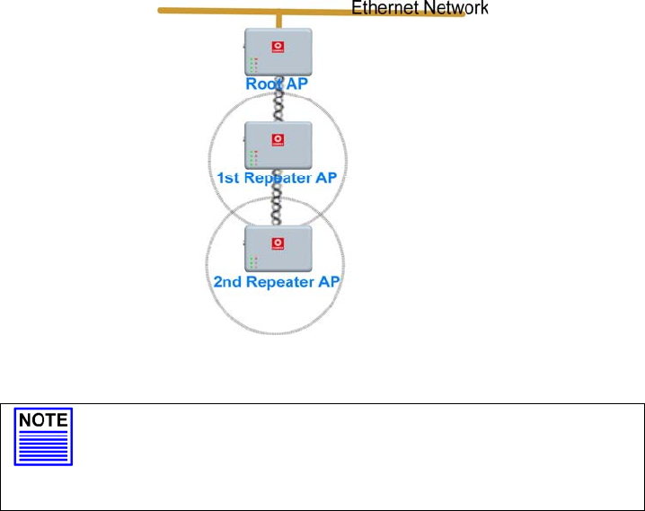
Setup Repeater
A Repeater AP can connect to an AP only if the option Act as RootAP is
set or checked in the AP setup.
Example: Network diagram with 2 repeater hops.
NOTE
As bandwidth degrades with every repeater hop it
is recommended that a limit of 4 hops is not
exceeded.
Page 128
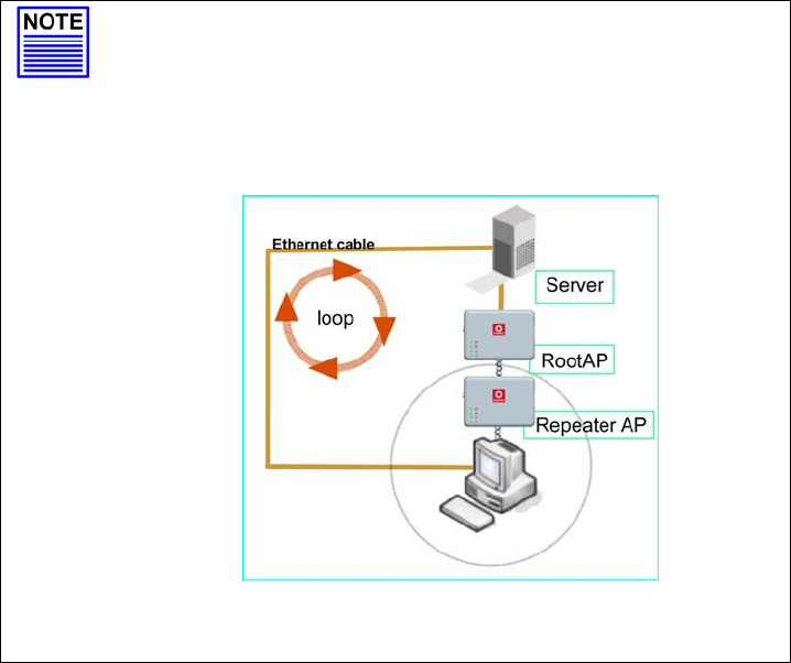
NOTE
DO NOT physically connect your PC to the server
via Ethernet cable in addition to the wireless
connection, as doing so will create a loop that is
not prevented by wireless loop preventing feature.
Page 129
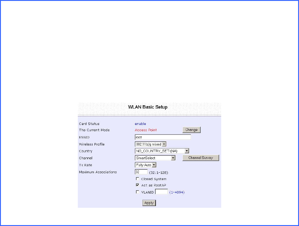
Follow these settings to setup the root AP.
R
Ro
oo
ot
t
A
AP
P
S
Se
et
tt
ti
in
ng
gs
s:
:
Click on W
WL
LA
AN
N
S
Se
et
tu
up
p from the C
CO
ON
NF
FI
IG
GU
UR
RA
AT
TI
IO
ON
N menu. You will see the sub-menus
expanded under W
WL
LA
AN
N
S
Se
et
tu
up
p. Click on B
Ba
as
si
ic
c.
Ensure that T
Th
he
e
C
Cu
ur
rr
re
en
nt
t
M
Mo
od
de
e
is set to A
Ac
cc
ce
es
ss
s
P
Po
oi
in
nt
t.
To change T
Th
he
e
C
Cu
ur
rr
re
en
nt
t
M
Mo
od
de
e, please refer to: Common Configuration – WLAN
Setup - To Configure the Basic Setup of the Wireless Mode.
Select A
Ac
ct
t
a
as
s
R
Ro
oo
ot
tA
AP
P.
Click A
Ap
pp
pl
ly
y.
Page 130
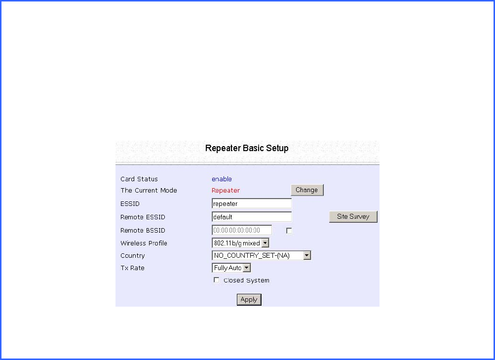
Follow these settings to setup the repeater.
R
Re
ep
pe
ea
at
te
er
r
S
Se
et
tt
ti
in
ng
gs
s:
:
Click on W
WL
LA
AN
N
S
Se
et
tu
up
p from the C
CO
ON
NF
FI
IG
GU
UR
RA
AT
TI
IO
ON
N menu. You will see the sub-menus
expanded under W
WL
LA
AN
N
S
Se
et
tu
up
p. Click on B
Ba
as
si
ic
c.
Ensure that T
Th
he
e
C
Cu
ur
rr
re
en
nt
t
M
Mo
od
de
e
is set to R
Re
ep
pe
ea
at
te
er
r.
To change T
Th
he
e
C
Cu
ur
rr
re
en
nt
t
M
Mo
od
de
e, please refer to: Common Configuration – WLAN
Setup - To Configure the Basic Setup of the Wireless Mode.
Page 131
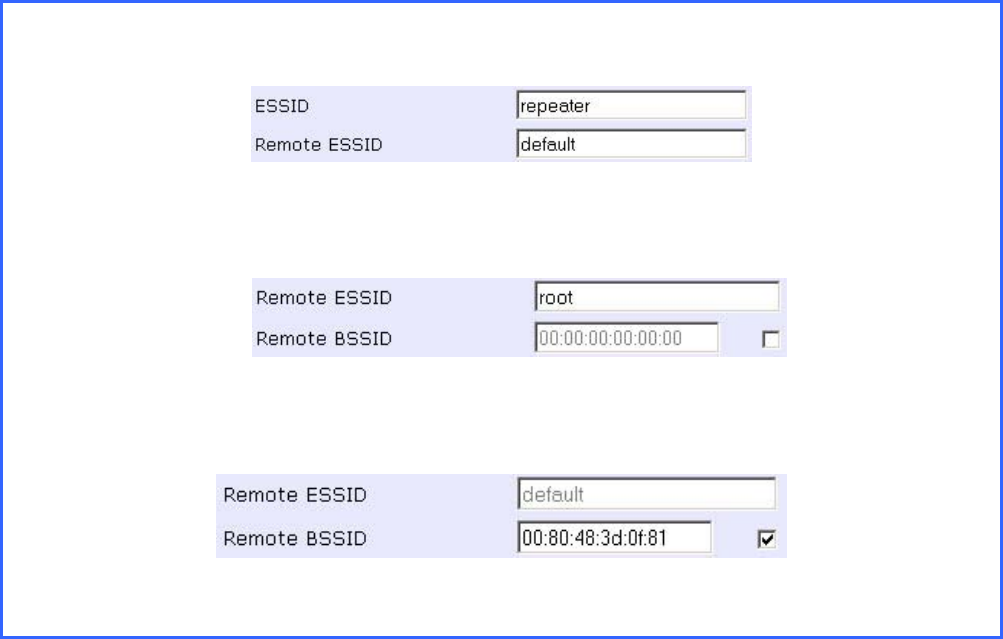
Options for defining the root AP:
• Accept the default R
Re
em
mo
ot
te
e
E
ES
SS
SI
ID
D (root AP’s SSID)
OR
• Enter the R
Re
em
mo
ot
te
e
E
ES
SS
SI
ID
D.
OR
• Check and enter the R
Re
em
mo
ot
te
e
B
BS
SS
SI
ID
D (root AP’s MAC address)
C
Cl
li
ic
ck
k
Apply.
.

Page 132
Secure your Wireless LAN
Step 1:
Select S
Se
ec
cu
ur
ri
it
ty
y from W
WL
LA
AN
N
S
Se
et
tu
up
p under the C
CO
ON
NF
FI
IG
GU
UR
RA
AT
TI
IO
ON
N menu.
Step 2:
Make a selection from the S
Se
ec
cu
ur
ri
it
ty
y
M
Mo
od
de
e drop-down list. The S
Se
ec
cu
ur
ri
it
ty
y
M
Mo
od
de
e is set to
N
NO
ON
NE
E by default.
Click on the A
Ap
pp
pl
ly
y button.
NOTE
All nodes in your network must share the same
wireless settings in order to communicate.
Page 133
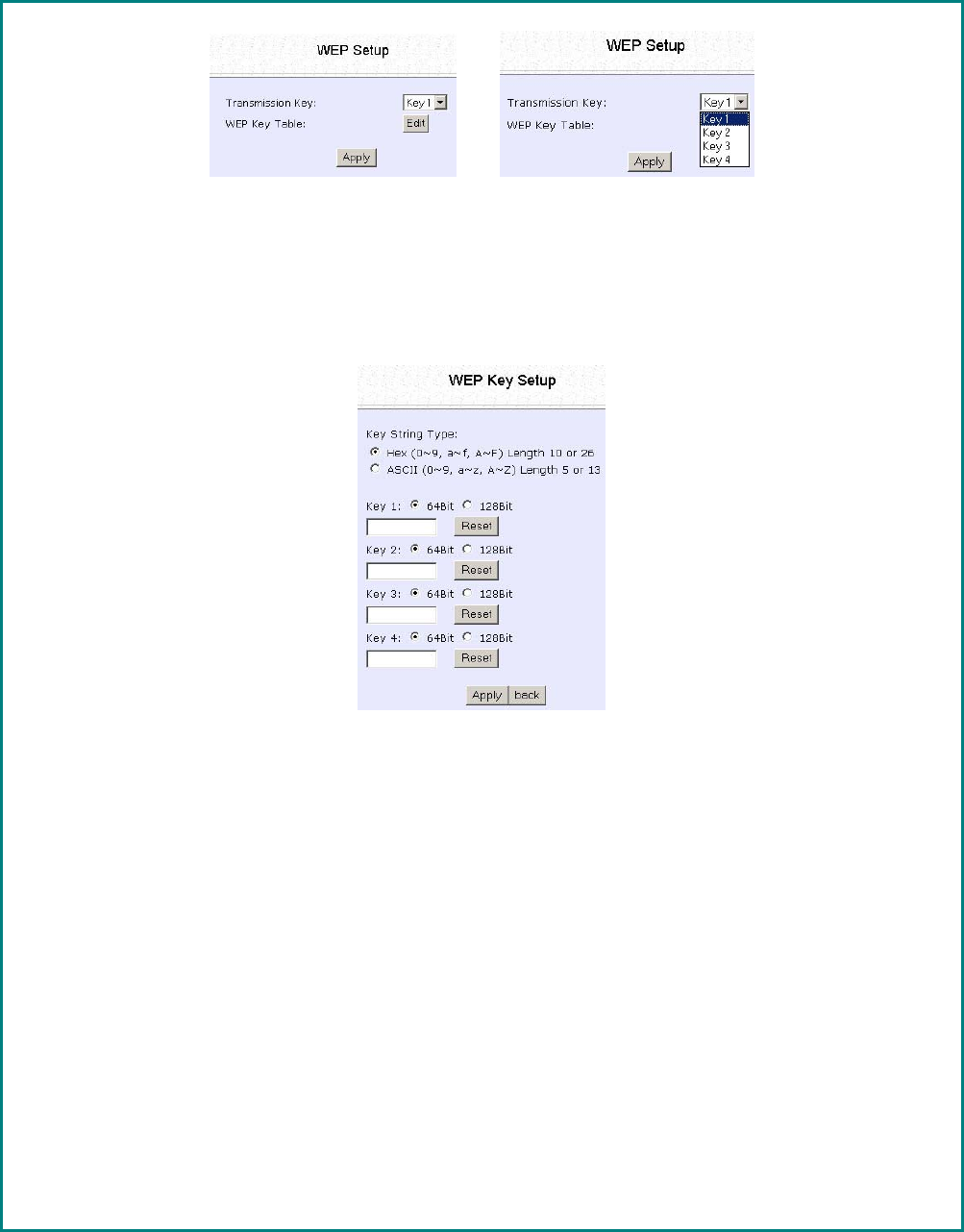
Setup WEP
At the WEP Setup page,
S
St
te
ep
p
1
1:
:
Select the T
Tr
ra
an
ns
sm
mi
is
ss
si
io
on
n
K
Ke
ey
y from the pull down menu:
•
•
K
Ke
ey
y
1
1
•
•
K
Ke
ey
y
2
2
•
•
K
Ke
ey
y
3
3
•
•
K
Ke
ey
y
4
4
S
St
te
ep
p
2
2:
:
Specify the k
ke
ey
y
e
en
nt
tr
ry
y
t
ty
yp
pe
e, by selecting either:
•
•
U
Us
se
e
H
He
ex
xa
ad
de
ec
ci
im
ma
al
l:
:
•
•
U
Us
se
e
A
AS
SC
CI
II
I
The access point lets you define up to four different transmission keys. It defines a set
of shared keys for network security. You must enter at least one WEP key to enable
security using a shared key.
S
St
te
ep
p
3
3:
:
Select the l
le
en
ng
gt
th
h of each encryption key:
•
•
6
64
4-
-
b
bi
it
t
W
WE
EP
P
10 hexadecimal or 5 ASCII Text
•
•
1
12
28
8-
-b
bi
it
t
W
WE
EP
P
26 hexadecimal or 13 ASCII Text
To clear the values that you have entered in the field, click on the R
Re
es
se
et
t button.
Click on the A
Ap
pp
pl
ly
y button and reboot your access point.
Page 134
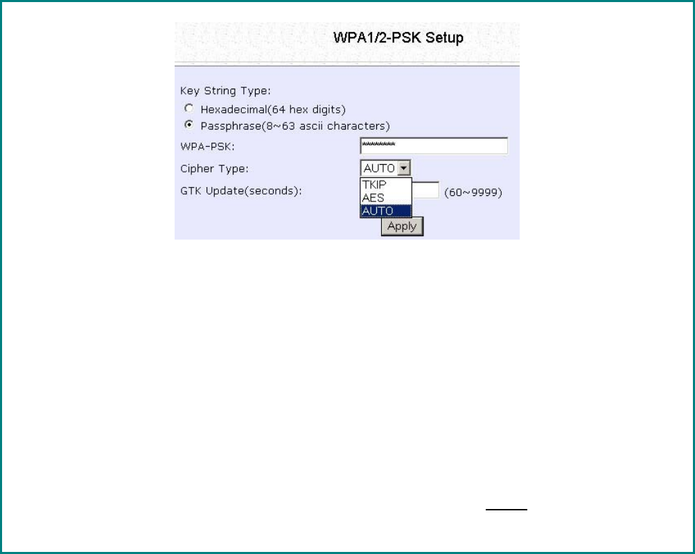
Setup WPA-Personal
(Available in Access Point, Repeater and Gateway Modes)
Follow these steps if you have activated the WPA-Personal, WPA2-
Personal or WPA-Personal-AUTO security modes.
At the W
WP
PA
A1
1/
/2
2-
-P
PS
SK
K
S
Se
et
tu
up
p page,
S
St
te
ep
p
1
1:
:
Specify the k
ke
ey
y
e
en
nt
tr
ry
y
t
ty
yp
pe
e, by selecting either:
•
•
P
Pa
as
ss
sp
ph
hr
ra
as
se
e
(
(A
Al
lp
ph
ha
an
nu
um
me
er
ri
ic
c
c
ch
ha
ar
ra
ac
ct
te
er
rs
s)
)
•
•
H
He
ex
xa
ad
de
ec
ci
im
ma
al
l
S
St
te
ep
p
2
2:
:
Fill in the pre-shared network key:
If you are using the P
Pa
as
ss
sp
ph
hr
ra
as
se
e format, your entry can consist of a minimum of 8
alphanumeric characters or a maximum of 63 alphanumeric characters.
Otherwise, when using the H
He
ex
xa
ad
de
ec
ci
im
ma
al
l format, your entry MUST consist of 64
hexadecimal characters.

Page 135
S
St
te
ep
p
3
3:
:
For WPA-Personal
Set the C
Ci
ip
ph
he
er
r
T
Ty
yp
pe
e to T
TK
KI
IP
P.
WPA replaces WEP with a strong encryption technology called Temporal Key
Integrity Protocol (TKIP) with Message Integrity Check (MIC).
For WPA2-Personal
Set the C
Ci
ip
ph
he
er
r
T
Ty
yp
pe
e to A
AE
ES
S.
Advanced Encryption Standard (AES) is a stronger symmetric 128-bit block data
encryption technique. AES is a requirement of WPA2 under the IEEE 802.11i
standard.
For WPA-Personal-AUTO
Set the C
Ci
ip
ph
he
er
r
T
Ty
yp
pe
e to A
Au
ut
to
o to allow the access point to automatically detect the
cipher type to use.
S
St
te
ep
p
4
4:
:
Enter the G
GT
TK
K
(
(G
Gr
ro
ou
up
p
T
Tr
ra
an
ns
si
ie
en
nt
t
K
Ke
ey
y)
)
U
Up
pd
da
at
te
es
s.
This is the length of time after which the access point will automatically generate a
new shared key to secure multicast/broadcast traffic among all stations that are
communicating with it. By default, the value is 600 seconds.
S
St
te
ep
p
5
5:
:
Click the A
Ap
pp
pl
ly
y
button and reboot your system, after which your settings will
become effective.
Page 136
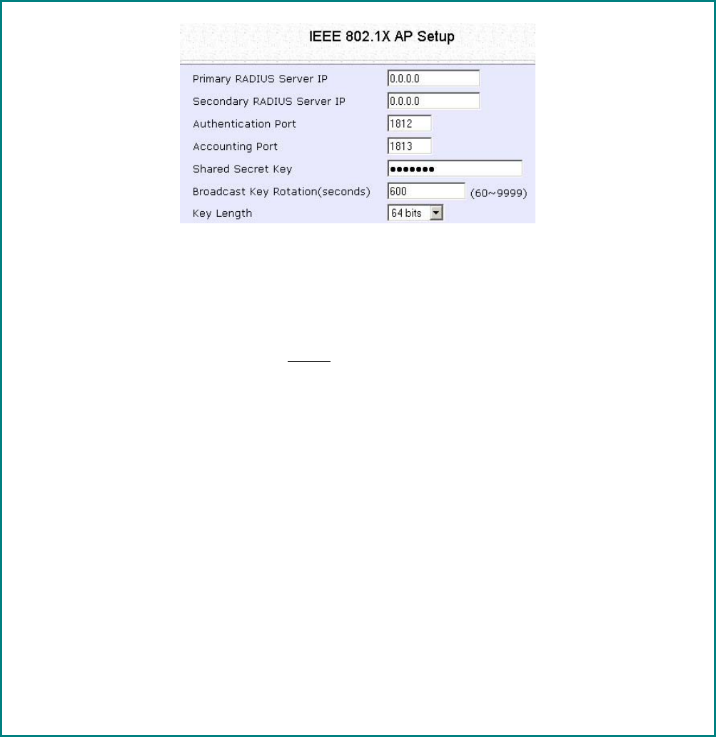
Setup 802.1x/RADIUS for Access Point
(Available in Access Point, Repeater and Gateway Modes)
At the IEEE 802.1x AP Setup page,
S
St
te
ep
p
1
1:
:
Key in the IP address of the P
Pr
ri
im
ma
ar
ry
y
R
RA
AD
DI
IU
US
S
S
Se
er
rv
ve
er
r in your WLAN. You can optionally
add in the IP address of a S
Se
ec
co
on
nd
da
ar
ry
y
R
RA
AD
DI
IU
US
S
S
Se
er
rv
ve
er
r, if any.
The RADIUS authentication server MUST be in the same subnet as the access point.
S
St
te
ep
p
2
2:
:
By default, the value for A
Au
ut
th
he
en
nt
ti
ic
ca
at
ti
io
on
n
P
Po
or
rt
t number is 1
18
81
12
2. You can leave this
value as it is. This value must be set to be the same as the one in the RADIUS server.
S
St
te
ep
p
3
3:
:
By default, the value for A
Ac
cc
co
ou
un
nt
ti
in
ng
g
P
Po
or
rt
t number is 1
18
81
13
3. You can leave this value
as it is. This value must be set to be the same as the one in the RADIUS server.
S
St
te
ep
p
4
4:
:
Enter the S
Sh
ha
ar
re
ed
d
S
Se
ec
cr
re
et
t
K
Ke
ey
y in the field provided.
S
St
te
ep
p
5
5:
:
By default, the B
Br
ro
oa
ad
dc
ca
as
st
t
K
Ke
ey
y
R
Ro
ot
ta
at
ti
io
on
n is set as 6
60
00
0 seconds. You may leave this
value as its default setting.

Page 137
S
St
te
ep
p
6
6:
:
Select the l
le
en
ng
gt
th
h of each encryption key:
•
•
6
64
4-
-
b
bi
it
t
10 hexadecimal or 5 ASCII Text
•
•
1
12
28
8-
-b
bi
it
t
26 hexadecimal or 13 ASCII Text
S
St
te
ep
p
7
7:
:
Click the A
Ap
pp
pl
ly
y
button and reboot your system, after which your settings will
become effective.
Page 138
Setup 802.1x/RADIUS for Client
(Available in Client, Transparent Client, Wireless Routing Client and
Wireless Adapter Modes)
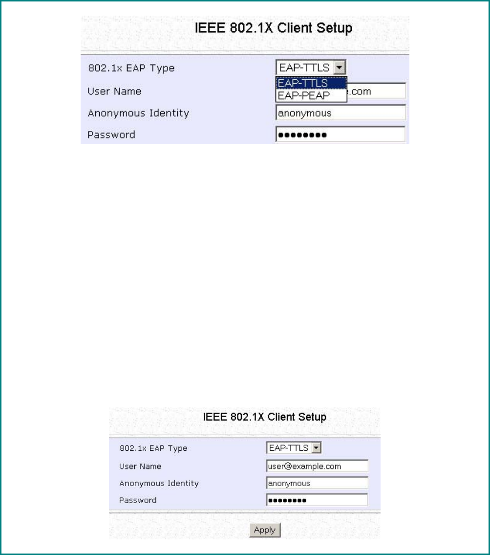
At the IEEE 802.1x Client Setup page,
S
St
te
ep
p
1
1:
:
Select whether to use E
EA
AP
P-
-T
TT
TL
LS
S
or E
EA
AP
P-
-P
PE
EA
AP
P 802.1x EAP Type.
Step 2:
Both E
EA
AP
P-
-T
TT
TL
LS
S (Extensible Authentication Protocol - Tunneled Transport Layer
Security) and E
EA
AP
P-
-P
PE
EA
AP
P (Protected Extensible Authentication Protocol) support
identity hiding. In the WLAN, the access point generates an identity request. To
preserve anonymity, the client responds with only enough information to allow the
RADIUS server to process the request.
I
If
f
u
us
si
in
ng
g
EAP-TTLS
8
80
02
2.
.1
1x
x
E
EA
AP
P
T
Ty
yp
pe
e:
:
• Enter the U
Us
se
er
r
N
Na
am
me
e.
• Enter the A
An
no
on
ny
ym
mo
ou
us
s
I
Id
de
en
nt
ti
it
ty
y attribute for EAP-TTLS.
• Enter the P
Pa
as
ss
sw
wo
or
rd
d.
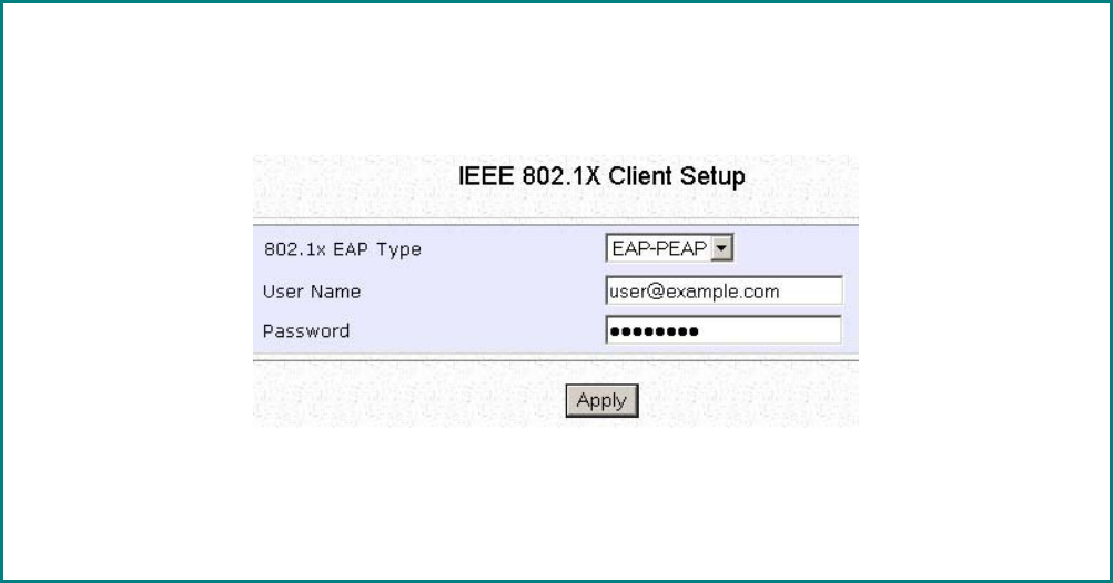
Page 139
I
If
f
u
us
si
in
ng
g
EAP-PEAP
8
80
02
2.
.1
1x
x
E
EA
AP
P
T
Ty
yp
pe
e:
:
• Enter the U
Us
se
er
r
N
Na
am
me
e.
• Enter the P
Pa
as
ss
sw
wo
or
rd
d.
S
St
te
ep
p
3
3:
:
Click the A
Ap
pp
pl
ly
y
button and reboot your system, after which your settings will
become effective.
Page 140
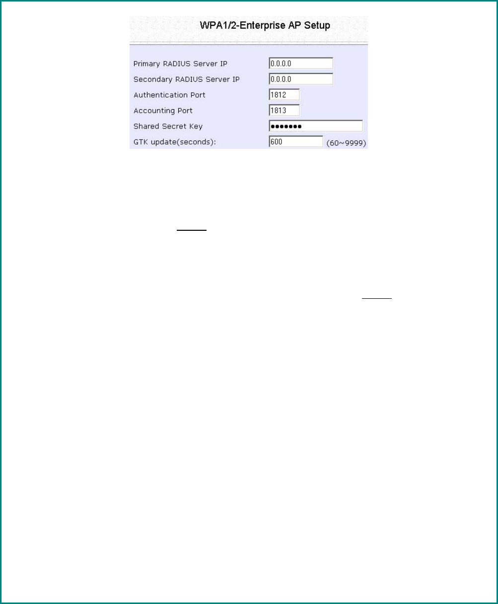
Setup WPA Enterprise for Access Point
(Available in Access Point, Repeater and Gateway Modes)
Follow these steps if you have selected the WPA1-Enterprise, WPA2-
Enterprise, or WPA-Enterprise-AUTO security modes.
At the W
WP
PA
A1
1/
/2
2-
-E
En
nt
te
er
rp
pr
ri
is
se
e
A
AP
P
S
Se
et
tu
up
p page,
S
St
te
ep
p
1
1:
:
Key in the IP address of the P
Pr
ri
im
ma
ar
ry
y
R
RA
AD
DI
IU
US
S
S
Se
er
rv
ve
er
r in your WLAN.
You can optionally add in the IP address of a S
Se
ec
co
on
nd
da
ar
ry
y
R
RA
AD
DI
IU
US
S
S
Se
er
rv
ve
er
r, if any. The
RADIUS authentication server MUST be in the same subnet as the access point.
S
St
te
ep
p
2
2:
:
By default, the value for A
Au
ut
th
he
en
nt
ti
ic
ca
at
ti
io
on
n
P
Po
or
rt
t number is 1
18
81
12
2. You can either leave
this value as it is or key in a different Authentication Port but it MUST match the
corresponding port of the RADIUS server.
S
St
te
ep
p
3
3:
:
By default, the value for A
Ac
cc
co
ou
un
nt
ti
in
ng
g
P
Po
or
rt
t is 1
18
81
13
3. You can leave this value as it is. This
value must be set to be the same as the one in the RADIUS server.
S
St
te
ep
p
4
4:
:
Enter the S
Sh
ha
ar
re
ed
d
S
Se
ec
cr
re
et
t
K
Ke
ey
y used to validate client-server RADIUS communications.
S
St
te
ep
p
5
5:
:
Enter the G
GT
TK
K
(
(G
Gr
ro
ou
up
p
T
Tr
ra
an
ns
si
ie
en
nt
t
K
Ke
ey
y)
)
U
Up
pd
da
at
te
es
s.
This is the length of time after which the access point will automatically generate a
new shared key to secure multicast/broadcast traffic among all stations that are
communicating with it. By default, the value is 600 seconds.
S
St
te
ep
p
6
6:
:
Click the A
Ap
pp
pl
ly
y
button and reboot your system, after which your settings will
become effective.
Page 141
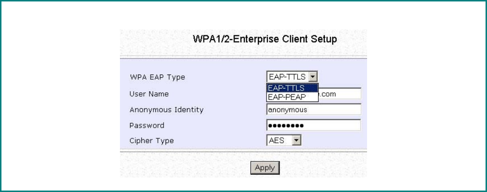
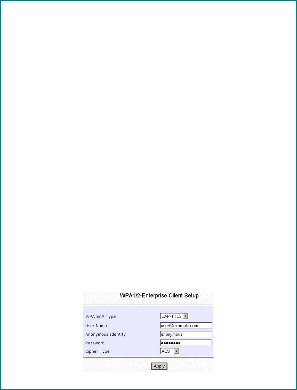
Setup WPA Enterprise for Client
(Available in Client, Transparent Client, Wireless Routing Client and
Wireless Adapter Modes)
Follow these steps if you have selected the WPA1-Enterprise, WPA2-
Enterprise, or WPA-Enterprise-AUTO security modes.
At the W
WP
PA
A1
1/
/2
2-
-E
En
nt
te
er
rp
pr
ri
is
se
e
C
Cl
li
ie
en
nt
t
S
Se
et
tu
up
p page,
Page 142
S
St
te
ep
p
1
1:
:
Select whether to use E
EA
AP
P-
-T
TT
TL
LS
S
or E
EA
AP
P-
-P
PE
EA
AP
P WPA EAP Type.
Step 2:
Both E
EA
AP
P-
-T
TT
TL
LS
S (Extensible Authentication Protocol - Tunneled Transport Layer
Security) and E
EA
AP
P-
-P
PE
EA
AP
P (Protected Extensible Authentication Protocol) support
identity hiding. In the WLAN, the access point generates an identity request. To
preserve anonymity, the client responds with only enough information to allow the
RADIUS server to process the request.
I
If
f
u
us
si
in
ng
g
EAP-TTLS
W
WP
PA
A
E
EA
AP
P
T
Ty
yp
pe
e:
:
• Enter the U
Us
se
er
r
N
Na
am
me
e.
• Enter the A
An
no
on
ny
ym
mo
ou
us
s
I
Id
de
en
nt
ti
it
ty
y attribute for EAP-TTLS.
• Enter the P
Pa
as
ss
sw
wo
or
rd
d.
• Enter the C
Ci
ip
ph
he
er
r
T
Ty
yp
pe
e.
For WPA-Enterprise
Set the C
Ci
ip
ph
he
er
r
T
Ty
yp
pe
e to T
TK
KI
IP
P.
WPA replaces WEP with a strong encryption technology called Temporal Key
Integrity Protocol (TKIP) with Message Integrity Check (MIC).
For WPA2- Enterprise
Set the
C
Ci
ip
ph
he
er
r
T
Ty
yp
pe
e to A
AE
ES
S.
Advanced Encryption Standard (AES) is a symmetric 128-bit block data encryption
technique. It is a requirement of WPA2 under the IEEE 802.11i standard.
For WPA- Enterprise -AUTO
Set the C
Ci
ip
ph
he
er
r
T
Ty
yp
pe
e to A
Au
ut
to
o to allow the access point to automatically detect the
cipher type to use.
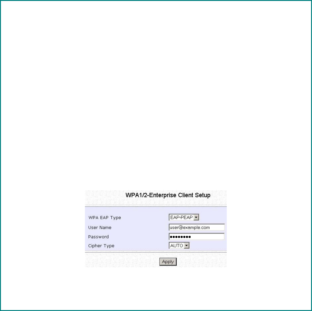
Page 143
I
If
f
u
us
si
in
ng
g
EAP-PEAP
W
WP
PA
A
E
EA
AP
P
T
Ty
yp
pe
e:
:
• Enter the U
Us
se
er
r
N
Na
am
me
e.
• Enter the A
An
no
on
ny
ym
mo
ou
us
s
I
Id
de
en
nt
ti
it
ty
y attribute for EAP-TTLS.
• Enter the P
Pa
as
ss
sw
wo
or
rd
d.
• Enter the C
Ci
ip
ph
he
er
r
T
Ty
yp
pe
e.
For WPA-Enterprise
Set the C
Ci
ip
ph
he
er
r
T
Ty
yp
pe
e to T
TK
KI
IP
P.
WPA replaces WEP with a strong encryption technology called Temporal Key
Integrity Protocol (TKIP) with Message Integrity Check (MIC).
For WPA2- Enterprise
Set the
C
Ci
ip
ph
he
er
r
T
Ty
yp
pe
e to A
AE
ES
S.
Advanced Encryption Standard (AES) is a symmetric 128-bit block data encryption
technique. It is a requirement of WPA2 under the IEEE 802.11i standard.
For WPA- Enterprise -AUTO
Set the C
Ci
ip
ph
he
er
r
T
Ty
yp
pe
e to A
Au
ut
to
o to allow the access point to automatically detect the
cipher type to use.
S
St
te
ep
p
3
3:
:
Click the A
Ap
pp
pl
ly
y
button and reboot your system, after which your settings will
become effective.
Page 144
Configure the Security Features
Use Packet Filtering
Packet filtering selectively allows /disallows applications from Internet
connection.
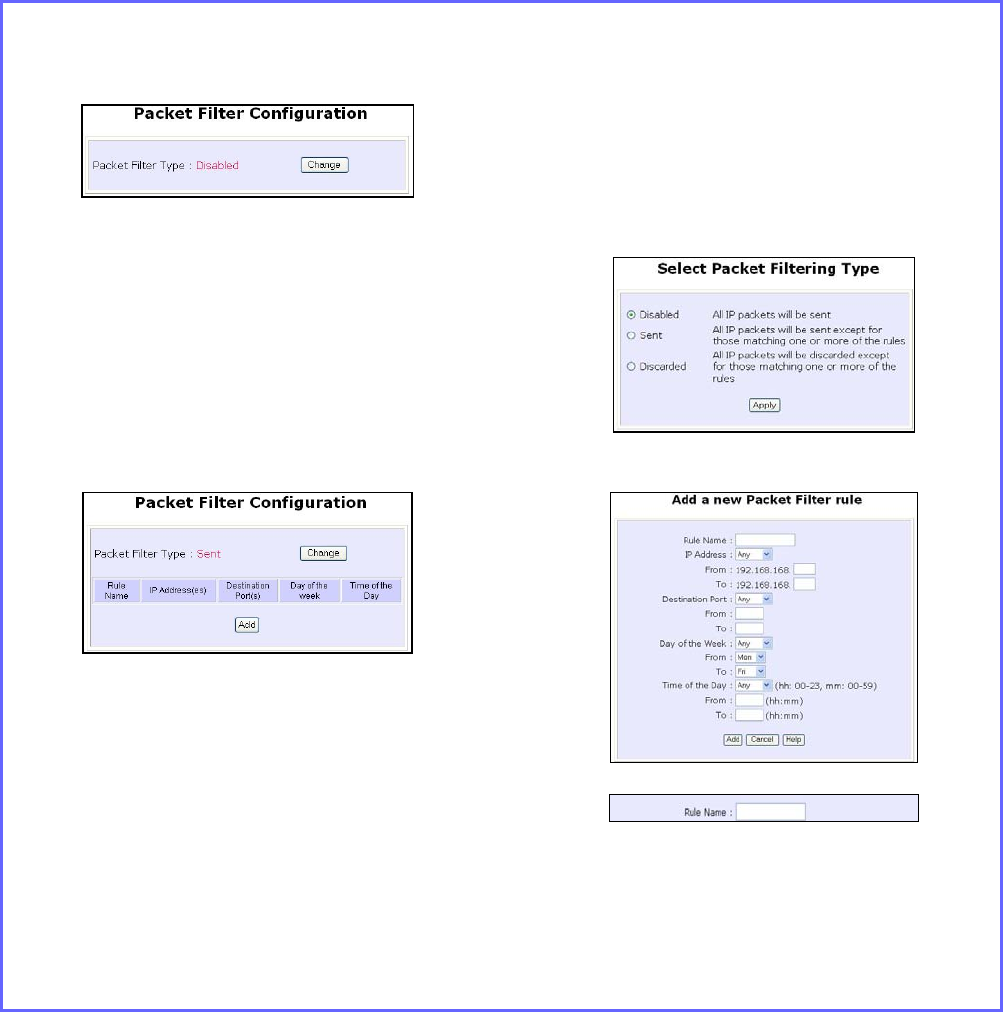
Configure Packet Filtering
(Available in Wireless Routing Client and Gateway modes)
Step 1:
Select P
Pa
ac
ck
ke
et
t
F
Fi
il
lt
te
er
ri
in
ng
g from the S
Se
ec
cu
ur
ri
it
ty
y
C
Co
on
nf
fi
ig
gu
ur
ra
at
ti
io
on
n command menu.
Step 2:
Select the P
Pa
ac
ck
ke
et
t
F
Fi
il
lt
te
er
r
T
Ty
yp
pe
e by
clicking on the C
Ch
ha
an
ng
ge
e button.
Step 3:
Select from three choices: D
Di
is
sa
ab
bl
le
ed
d,
S
Se
en
nt
t, D
Di
is
sc
ca
ar
rd
de
ed
d, and then click on the
A
Ap
pp
pl
ly
y button. The default is D
Di
is
sa
ab
bl
le
ed
d,
which allows all packets to be sent.
Step 4:
Click on the A
Ad
dd
d button and you will be
able to define the details of your P
Pa
ac
ck
ke
et
t
F
Fi
il
lt
te
er
r
R
Ru
ul
le
e from the screen on the right.
4a). Enter Rule Name for this new
packet filtering rule. For example,
BlockCS
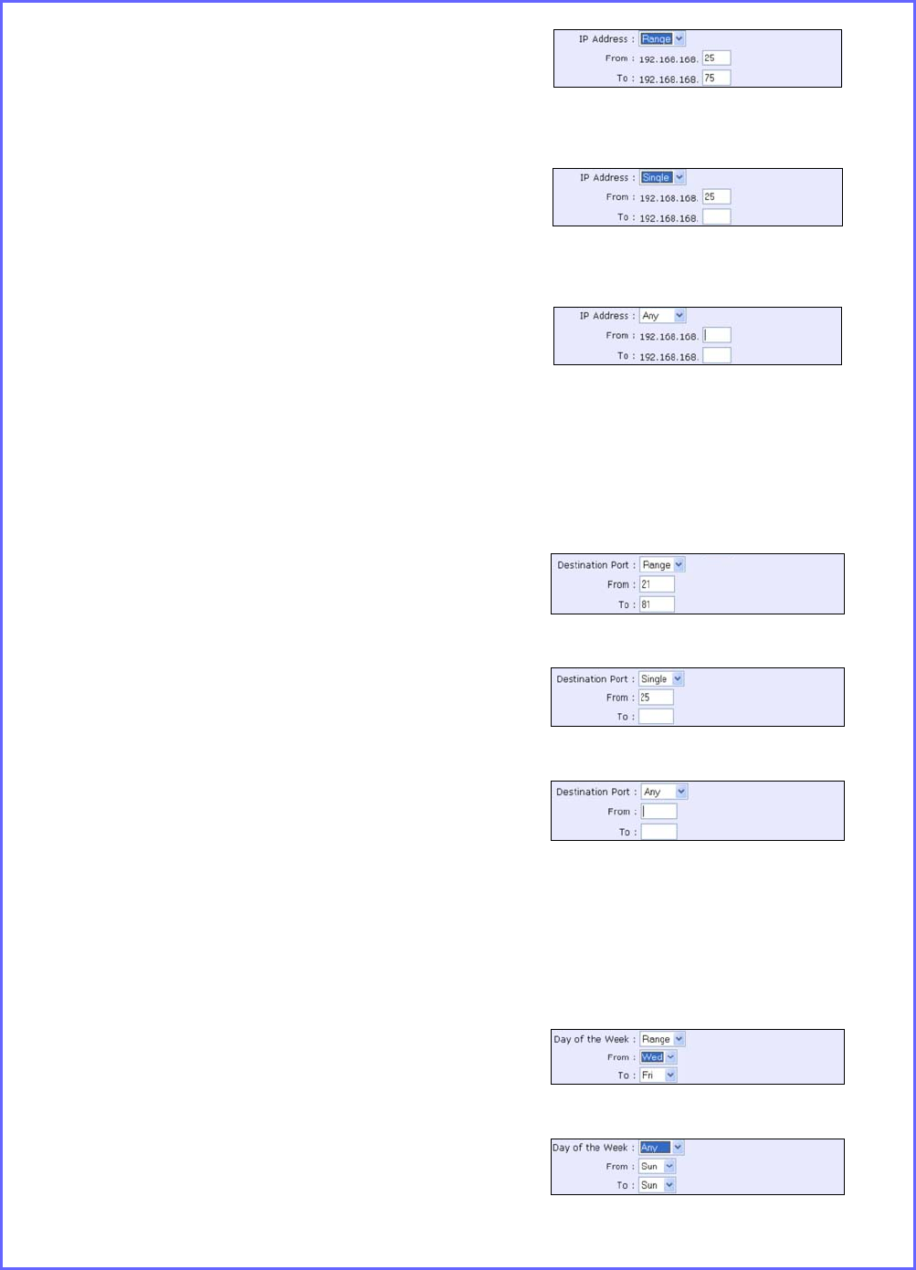
4b). From the IP Address drop down
list, select whether to apply the
rule to:
Page 145
A Range of IP addresses
In this case, you will have to define
(From) which IP address (To) which
IP address, your range extends.
A Single IP address
Here, you need only specify the
source IP address in the (From)
field.
Any IP address
You may here, leave both, the
(From) as well as the (To) fields,
blank. Here, the rule will apply to
all IP addresses.
4c). At the Destination Port drop down
list, select either:
A Range of TCP ports
In this case, you will have to define
(From) which port (To) which port,
your rule applies.
A Single TCP port
Here, you need only specify the
source port in the (From) field.
Any IP port
You may here, leave both, the
(From) as well as the (To) fields,
blank. Here, the rule will apply to
all ports.
4d). From the Day of the Week drop
down list, select whether the rule
should apply to:
A Range of days
Here, you will have to select (From)
which day (To) which day
Any day
In this case, you may skip both the
(From) as well as the (To) drop
down fields.
Page 146
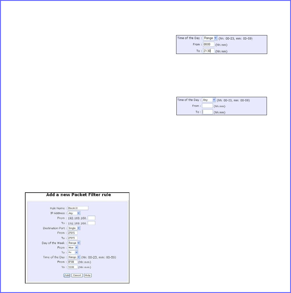
4e). At the Time of the Day drop down
list, you may also choose to apply
the rule to:
A Range of time
In which case, you have to specify
the time in the format HH:MM,
where HH may take any value
from 00 to 23 and MM, any value
from 00 to 59.
Any time
Here, you may leave both (From)
and (To) fields blank.
Step 5:
Click on the A
Ap
pp
pl
ly
y button to make the
new rule effective.
The F
Fi
il
lt
te
er
ri
in
ng
g
C
Co
on
nf
fi
ig
gu
ur
ra
at
ti
io
on
n table will then
be updated.
Step 6:
In this example, we would block an
application called CS from all PCs
(any IP address within the network)
from Monday to Friday 7am to
6pm, and this application is using
the port number 27015.
Therefore, for a rule we name
BlockCS, and add the entries
depicted on the left. Clicking on
the Add button will effect your
packet filter rule.
Page 147
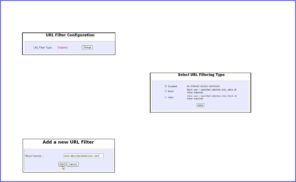
Use URL Filtering
URL Filtering allows you to block objectionable websites from your LAN
users.
Configure URL Filtering
(Available in Wireless Routing Client and Gateway modes)
Step 1:
Select U
UR
RL
L
F
Fi
il
lt
te
er
ri
in
ng
g from the S
Se
ec
cu
ur
ri
it
ty
y
C
Co
on
nf
fi
ig
gu
ur
ra
at
ti
io
on
n command menu.
Step 2:
To select the U
UR
RL
L
F
Fi
il
lt
te
er
r
T
Ty
yp
pe
e, click the
C
Ch
ha
an
ng
ge
e button.
Step 3:
Select to B
Bl
lo
oc
ck
k or A
Al
ll
lo
ow
w, and then
click on the A
Ap
pp
pl
ly
y button. The default
is D
Di
is
sa
ab
bl
le
ed
d, which allows all websites
to be accessed.
Then click the A
Ad
dd
d button.
Step 4:
For the H
Ho
os
st
t
N
Na
am
me
e field, input the web
site address that you wish to block. Then
click the A
Ad
dd
d button to complete your
setup.
Page 148
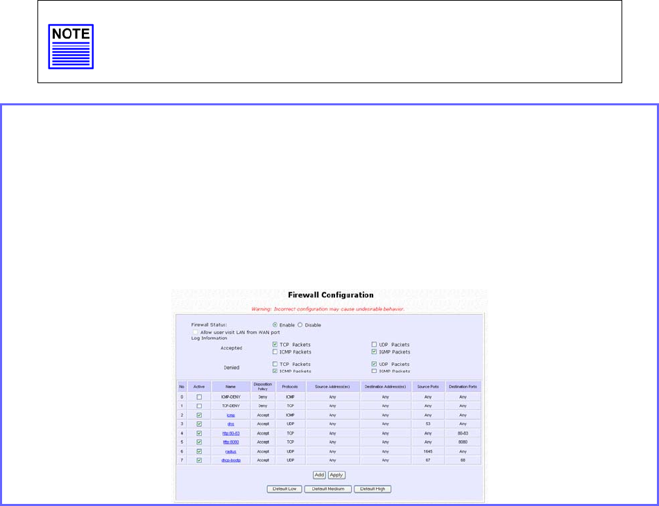
Configure the Firewall
Configure SPI Firewall
(Available in Wireless Routing Client and Gateway modes)
Stateful Packet Inspection (SPI) thwarts common hacker attacks like IP
Spoofing, Port Scanning, Ping of Death, and SynFlood by comparing
certain key parts of the packet to a database of trusted information
before allowing it through.
NOTE
Firewall security rules should be planned carefully as incorrect
configuration may cause improper network function.
Select F
Fi
ir
re
ew
wa
al
ll
l
C
Co
on
nf
fi
ig
gu
ur
ra
at
ti
io
on
n from the S
Se
ec
cu
ur
ri
it
ty
y
C
Co
on
nf
fi
ig
gu
ur
ra
at
ti
io
on
n command menu.
Enable the firewall. You can choose among the D
De
ef
fa
au
ul
lt
t
L
Lo
ow
w, D
De
ef
fa
au
ul
lt
t
M
Me
ed
di
iu
um
m or
D
De
ef
fa
au
ul
lt
t
H
Hi
ig
gh
h security options for convenient setup.
Then you may choose the type of network activity information you wish to log
for reference. Data activity arising from different types of protocol can be
recorded.
Page 149
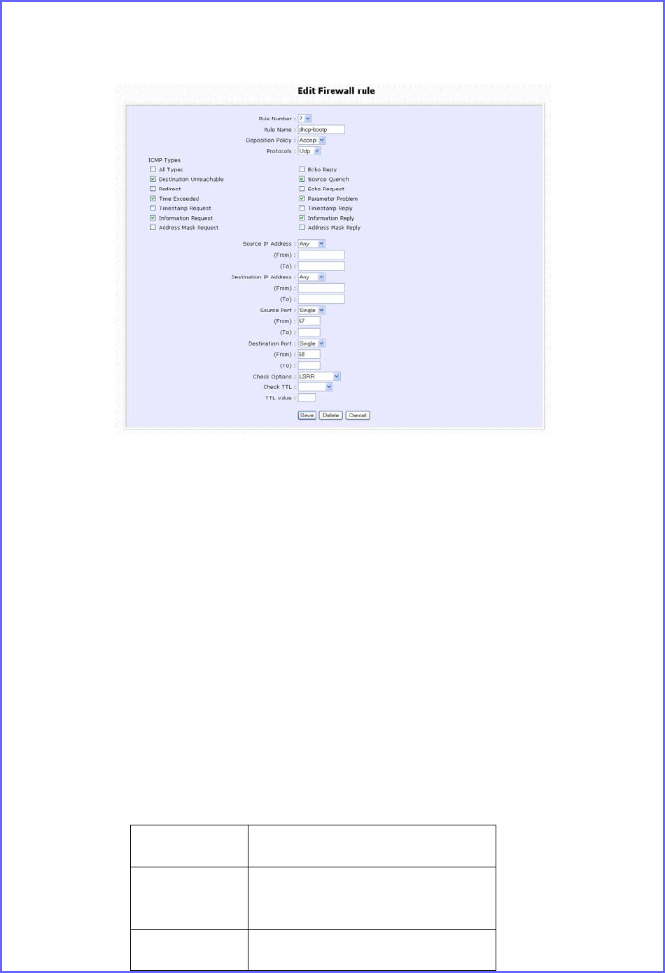
You may add more firewall rules for specific security purposes. Click on the A
Ad
dd
d
radio button at the screen shown above, followed by the E
Ed
di
it
t button.
Rule
Name : Enter a unique name to identify this firewall rule.
Disposition
Policy : This parameter determines whether the packets obeying the rule
should be accepted or denied by the firewall. Choose between
Accept and Deny.
Protocols : Users are allowed to select the type of data packet from: TCP,
UDP, ICMP, IGMP or ALL.
Note: If users select either ICMP or IGMP, they are required to
make further selection in the ICMP Types or IGMP Types
respectively.
ICMP
Types
: This IP protocol is used to report errors in IP packet routing. ICMP
serves as a form of flow control, although ICMP messages are
neither guaranteed to be received or transmitted.
ICMP
Packet Type Description
Echo
request Determines whether an IP
node (a host or a router) is
available on the network.
Echo reply Replies to an ICMP echo
re
q
uest.

Page 150
Destination
unreachabl
e
Informs the host that a
datagram cannot be
delivered.
Source
quench Informs the host to lower the
rate at which it sends
datagrams because of
congestion.
Redirect Informs the host of a
preferred route.
Time
exceeded Indicates that the Time-to-
Live (TTL) of an IP datagram
has expired.
Parameter
Problem Informs that host that there
is a problem in one the
ICMP parameter.
Timestamp
Request Information that is from the
ICMP data packet.
Information
Request Information that is from the
ICMP data packet.
Information
Reply Information that is from the
ICMP data packet.
IGMP
Types
: This IP protocol is used to establish host memberships in particular
multicast groups on a single network. The mechanisms of the
protocol allow a host to inform its local router, using Host
Membership Reports.
Host
Membership
Report
Information that is from the
IGMP data packet.
Host
Membership
Query
Information that is from the
IGMP data packet.
Leave Host
Message Information that is from the
ICMP data packet.
Source IP : This parameter allows you to specify workstation(s) generating
the data packets. Users can either set a single IP address or set a
range of IP addresses.
Destinatio
n IP : This parameter lets you specify the set of workstations that
receive the data packets. Users can either set a single IP address
or set a range of IP addresses.
Source
Port : You can control requests for using a specific application by
entering its port number here. Users can either set a single port
number or a range of port numbers.

Page 151
Destinatio
n Port : This parameter determines the application from the specified
destination port. Users can either set a single port number or a
range of port numbers.
Check
Options : This parameter refers to the options in the packet header. The
available selection options are abbreviated as follows:
SEC – Security
LSRR – Loose Source Routing
Timestamp – Timestamp
RR – Record Route
SID – Stream Identifier
SSRR – Strict Source Routing
RA – Router Alert
Check TTL : This parameter would let you screen packets according to their
Time-To-Live (TTL) value available options are:
1. Equal
2. Less than
3. Greater than
4. Not equal
Page 152
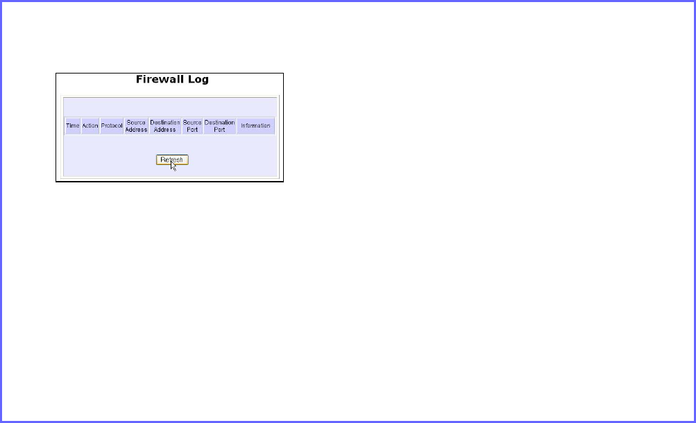
Use the Firewall Log
The Firewall Log captures and stores network traffic information such as
the type of data traffic, the time, the source and destination address /
port, as well as the action taken by the firewall.
View Firewall Logs
(Available in Wireless Routing Client and Gateway modes)
Step 1:
Select F
Fi
ir
re
ew
wa
al
ll
l
L
Lo
og
g
from the S
SE
EC
CU
UR
RI
IT
TY
Y
C
CO
ON
NF
FI
IG
GU
UR
RA
AT
TI
IO
ON
N command menu.
Step 2:
Click on the R
Re
ef
fr
re
es
sh
h button to see the
information captured in the log:
Time at which the packet was
detected by the firewall.
Action, which states whether the
packet was accepted or denied.
Protocol type of the packet.
Source Address from which the
packet originated
Destination Address to which the
packet was intended.
Source Port from which the packet
was initiated.
Destination Port to which the packet
was meant for.
Any Information.
Page 153
Administer the System
Use the System Tools
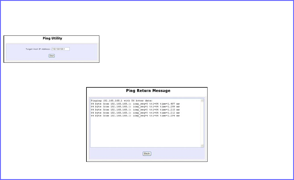
Use the Ping Utility
(Available in Wireless Routing Client and Gateway modes.)
You can check whether the access point can communicate (ping)
with another network host with the Ping Utility.
Step 1:
Select P
Pi
in
ng
g
U
Ut
ti
il
li
it
ty
y under the S
SY
YS
ST
TE
EM
M
T
TO
OO
OL
LS
S command menu.
Step 2:
Enter the IP address of the target host
to ping.
Click the S
St
ta
ar
rt
t button.
The Ping messages are displayed.
Page 154
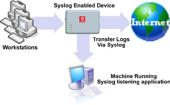
Use Syslog
Syslog forwards system log messages in a network to a machine
running a Syslog listening application. It is used to help in managing the
computer system and increase security on the network.
Freeware supporting Syslog is widely available for download from the
Internet.
This section shows how to:
• Setup Syslog.
• View logged information.
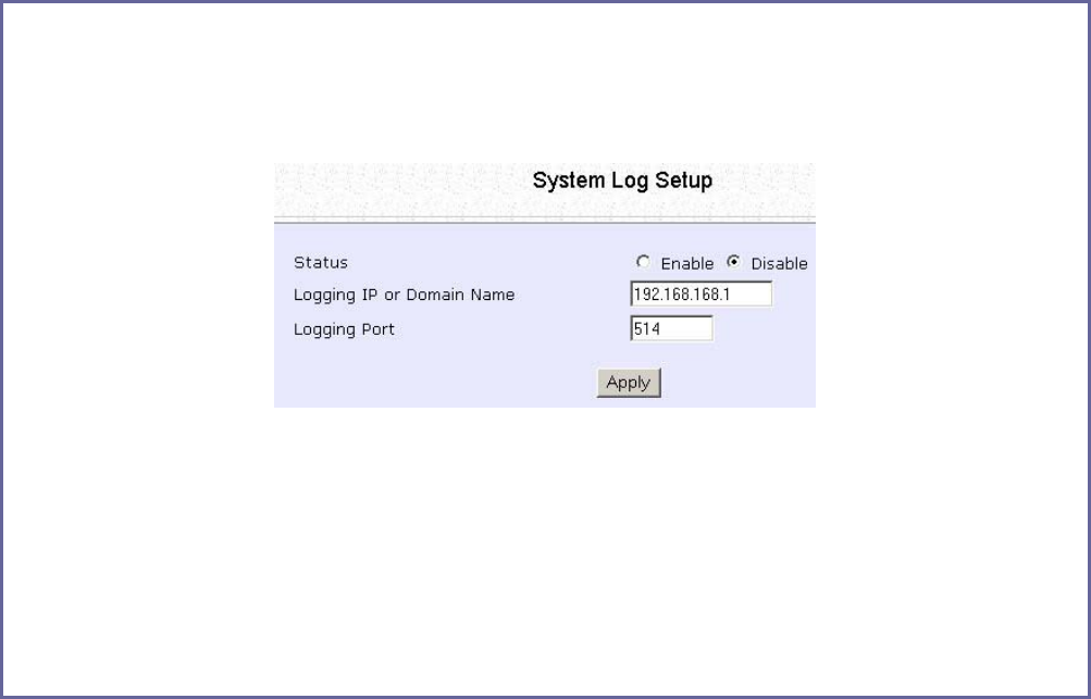
The System Log Setup page allows the user to:
• Enable or Disable system logging.
• Set the Remote IP Address or Domain Name and Remote Port for
the router to send the system log messages to.
Page 155
Follow these steps to setup Syslog:
Step 1:
Click on S
Sy
ys
sl
lo
og
g from the S
SY
YS
ST
TE
EM
M
T
TO
OO
OL
LS
S menu.
Step 2:
Select to E
En
na
ab
bl
le
e Syslog.
Enter the L
Lo
og
gg
gi
in
ng
g
I
IP
P
o
or
r
D
Do
om
ma
ai
in
n
N
Na
am
me
e
Enter the L
Lo
og
gg
gi
in
ng
g
P
Po
or
rt
t
Click A
Ap
pp
pl
ly
y to make the changes.
Page 156
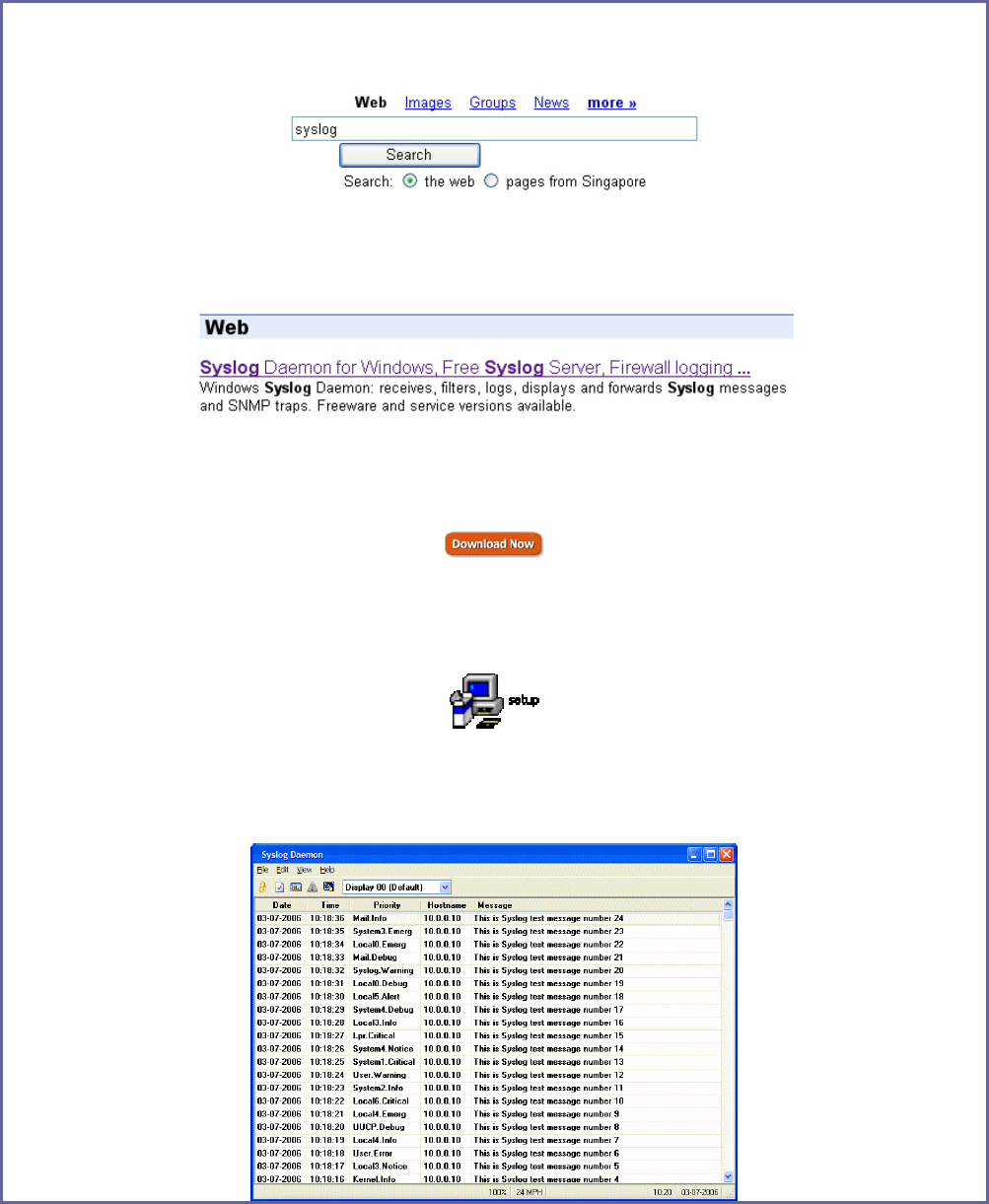
Follow these sample steps to view logged information:
Step 1:
Search for a Syslog listening application.
Step 2:
Select a Syslog listening application.
Step 3:
Download Syslog listening application.
Step 4:
Install Syslog listening application.
Step 5:
View logged information on Syslog listening application.
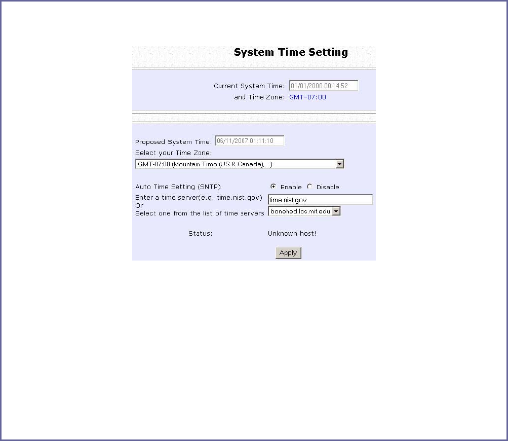
Page 157
Setup System Clock
Step 1:
Select S
Sy
ys
st
te
em
m
C
Cl
lo
oc
ck
k
S
Se
et
tu
up
p from the S
SY
YS
ST
TE
EM
M
T
TO
OO
OL
LS
S menu.
Step 2:
Select the appropriate time zone from the S
Se
el
le
ec
ct
t
t
to
o
C
Ch
ha
an
ng
ge
e
t
th
he
e
T
Ti
im
me
e
Z
Zo
on
ne
e
f
fo
or
r
t
th
he
e
R
Ro
ou
ut
te
er
r
L
Lo
oc
ca
at
ti
io
on
n drop-down list.
Step 3:
E
En
na
ab
bl
le
e the Auto Time Setting (SNTP) radio button. S
SN
NT
TP
P stands for Simple Network
Time Protocol and is used to synchronise computer clocks.
Step 4:
Fill in the T
Ti
im
me
e
S
Se
er
rv
ve
er
rs
s field and click on the A
Ap
pp
pl
ly
y button to effect the changes.
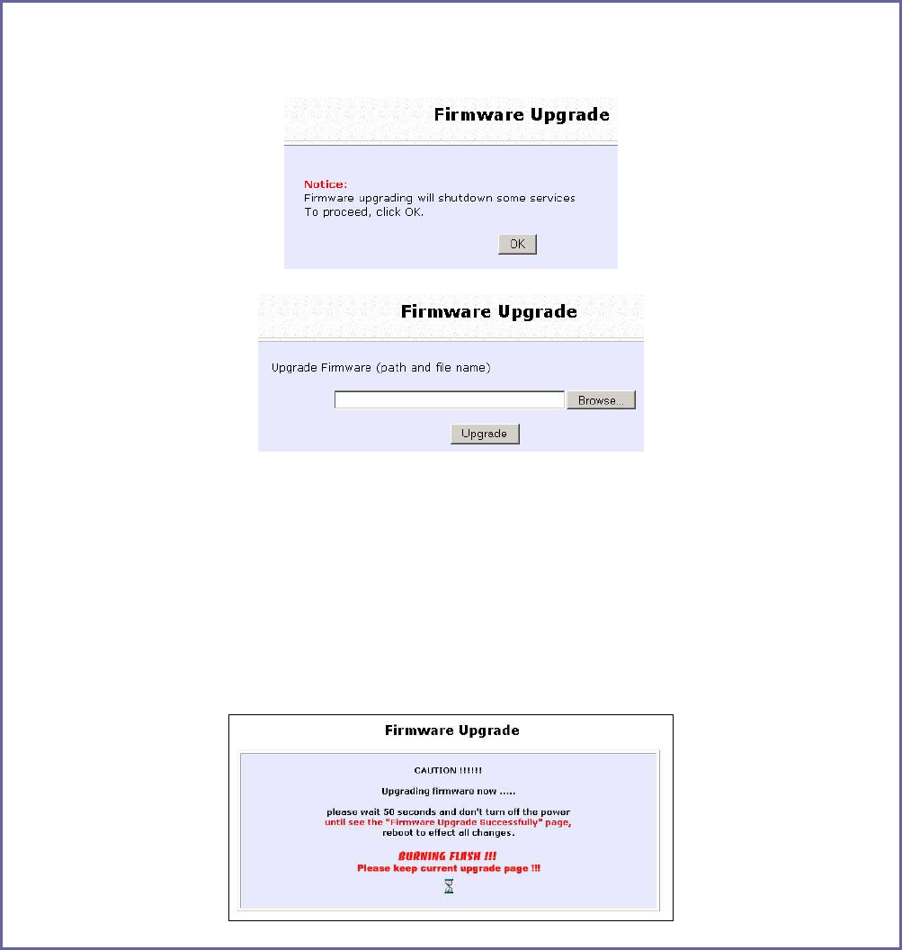
Page 158
Upgrade the Firmware with uConfig
You can check the types and version of your firmware by clicking on
About System from the HELP menu.
To begin with, ensure that you have the updated firmware available.
S
St
te
ep
p
1
1:
:
Select F
Fi
ir
rm
mw
wa
ar
re
e
U
Up
pg
gr
ra
ad
de
e from the S
SY
YS
ST
TE
EM
M
T
TO
OO
OL
LS
S menu.
S
St
te
ep
p
2
2:
:
Click on the B
Br
ro
ow
ws
se
e button to locate the file.
S
St
te
ep
p
3
3:
:
Click on the U
Up
pg
gr
ra
ad
de
e button.
Follow the instructions given during the upgrading process.
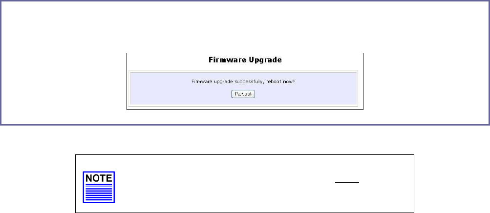
Page 159
S
St
te
ep
p
4
4:
:
You need to reboot the system after the firmware upgrade.
NOTE
The firmware upgrade process must NOT be
interrupted; otherwise the device might become
unusable.
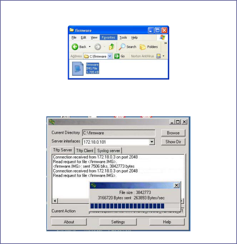
Page 160
Upgrade the Firmware with Command Line
Interface
You can check the types and version of your firmware by clicking on
About System from the HELP menu in UConfig.
Follow these steps to upgrade firmware from Command Line Interface
(CLI).
S
St
te
ep
p
1
1:
:
Ensure that you have the updated firmware available.
S
St
te
ep
p
2
2:
:
On the PC connected to the AP, run a TFTP server and setup to point to the same
firmware image filename.
Sample Screenshot
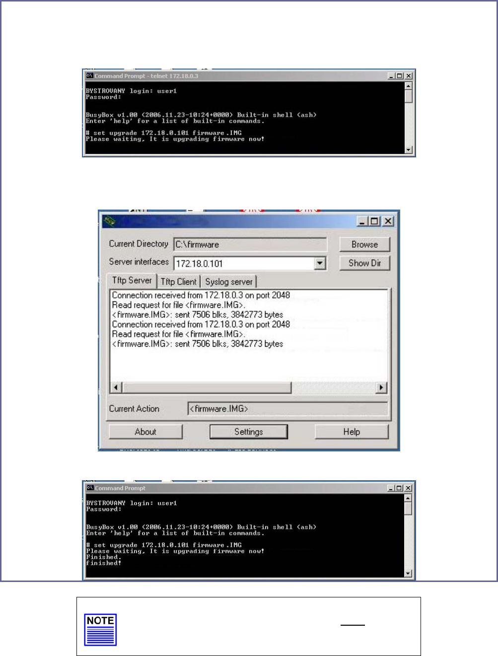
Page 161
S
St
te
ep
p
3
3:
:
In the Command Line Interface, enter the command with the IP address of the AP
and the filename of the firmware image as the parameters:
Set upgrade <IP address of AP> <firmware image filename>
S
St
te
ep
p
4
4:
:
These screens display when upgrade is done.
Sample Screenshot
NOTE
The firmware upgrade process must NOT be
interrupted; otherwise the device might become
unusable.

Page 162
Perform Firmware Recovery
If the system fails to launch properly, the access point will automatically
switch to loader mode and the diagnostic LED will remain lighted. The
firmware should then be reloaded.
Access Point State Diagnostic LED ( )
State
Corrupted firmware – access point
automatically switches to loader
mode
Blinks very fast
Recovery in progress ON
Successful recovery Blinks very slowly
Before starting, check the status of the diagnostic LED to confirm if
firmware failure has occurred.
S
St
te
ep
p
1
1:
:
Stop power supply and disconnect the access point from the network.
S
St
te
ep
p
2
2:
:
Connect the LAN port of the access point to the LAN port of your computer with an
MDI cable.
S
St
te
ep
p
3
3:
:
Power on the access point, and start up your computer. You are recommended to
set your computer’s IP address to 192.168.168.100 and its network mask to
255.255.255.0.
It is recommended that your computer IP address is set to 192.168.168.100 and the
network mask is set to 255.255.255.0
S
St
te
ep
p
4
4:
:
Insert the Product CD into the CD drive of your computer.

Page 163
S
St
te
ep
p
5
5:
:
From the Start menu, click Run and type cmd. When the command prompt window
appears, type in the following command:
X:\recovery\TFTP -i 192.168.168.1 PUT image_name.IMG, where X refers to your CD
drive and image_name.IMG refers to the firmware filename found in the Recovery
folder of the Product CD.
S
St
te
ep
p
6
6:
:
If you have downloaded a newer firmware and have saved it in your local hard disk
as: C:\accesspoint\accesspointxxx.IMG, then replace the command with this new
path and firmware name. For example:
C:\accesspoint\TFTP –i 192.168.168.1 PUT accesspointxxx.img
The recovery process takes place.
You can monitor the progress of the recovery process with the diagnostic LED.
When firmware restoration is complete, reboot the access point and it will be ready
to operate.
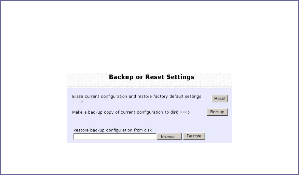
Page 164
Backup or Reset the Settings
You may choose to save the current configuration profile, create a
backup of it on your hard disk, restore an earlier saved profile, or to
reset the access point back to its default settings.
Reset your settings
S
St
te
ep
p
1
1:
:
Select B
Ba
ac
ck
ku
up
p
o
or
r
R
Re
es
se
et
t
S
Se
et
tt
ti
in
ng
gs
s from the S
SY
YS
ST
TE
EM
M
T
TO
OO
OL
LS
S menu.
S
St
te
ep
p
2
2:
:
To discard configurations made and restore the access point to its initial factory
settings, click on the R
Re
es
se
et
t button.
S
St
te
ep
p
3
3:
:
The system will prompt you to reboot your device, click on the R
Re
eb
bo
oo
ot
t button.
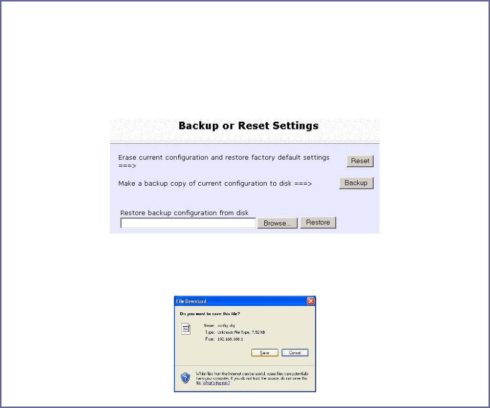
Page 165
Backup your Settings
S
St
te
ep
p
1
1:
:
Select B
Ba
ac
ck
ku
up
p
o
or
r
R
Re
es
se
et
t
S
Se
et
tt
ti
in
ng
gs
s from the S
SY
YS
ST
TE
EM
M
T
TO
OO
OL
LS
S menu.
S
St
te
ep
p
2
2:
:
To back up the current settings of your access point onto your hard disk drive, click
on the B
Ba
ac
ck
ku
up
p button.
S
St
te
ep
p
3
3:
:
Save your configuration file to your local disk.
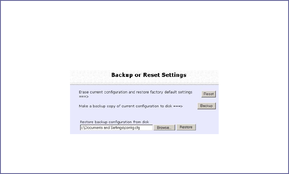
Page 166
Restore your Settings
S
St
te
ep
p
1
1:
:
Select B
Ba
ac
ck
ku
up
p
o
or
r
R
Re
es
se
et
t
S
Se
et
tt
ti
in
ng
gs
s from the S
SY
YS
ST
TE
EM
M
T
TO
OO
OL
LS
S menu.
S
St
te
ep
p
2
2:
:
To restore previously saved settings, click on the B
Br
ro
ow
ws
se
e…
… button and select the
folder where you saved your configuration file.
Click on the R
Re
es
st
to
or
re
e button and the system will prompt you to reboot your device.
S
St
te
ep
p
2
2:
:
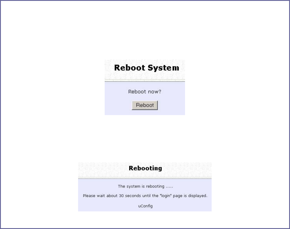
Page 167
Reboot the System
Most of the changes you make to the system settings require a system
reboot before the new parameters can take effect.
S
St
te
ep
p
1
1:
:
Select R
Re
eb
bo
oo
ot
t
S
Sy
ys
st
te
em
m from the S
SY
YS
ST
TE
EM
M
T
TO
OO
OL
LS
S menu.
S
St
te
ep
p
2
2:
:
Click on the R
Re
eb
bo
oo
ot
t button.
S
St
te
ep
p
3
3:
:
Wait for the system to reboot and the login page will be displayed.
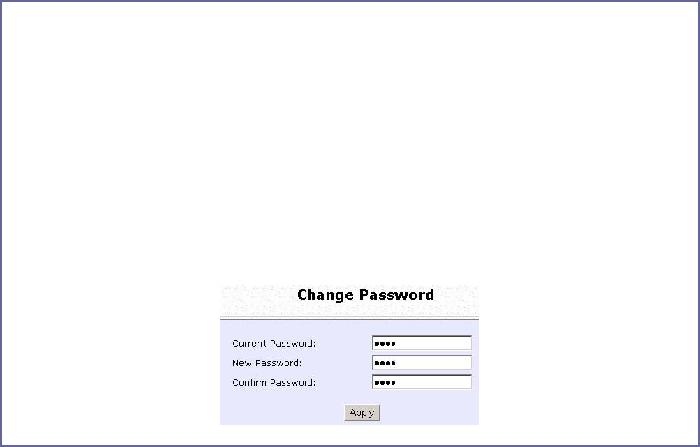
Page 168
Change the Password
It is recommended that the login password is changed from the factory
default password.
S
St
te
ep
p
1
1:
:
Select C
Ch
ha
an
ng
ge
e
P
Pa
as
ss
sw
wo
or
rd
d from the S
SY
YS
ST
TE
EM
M
T
TO
OO
OL
LS
S menu.
S
St
te
ep
p
2
2:
:
Key in the C
Cu
ur
rr
re
en
nt
t
P
Pa
as
ss
sw
wo
or
rd
d. The password is case-sensitive and defaulted to
password
Enter the N
Ne
ew
w
P
Pa
as
ss
sw
wo
or
rd
d field and then C
Co
on
nf
fi
ir
rm
m
P
Pa
as
ss
sw
wo
or
rd
d.
S
St
te
ep
p
3
3:
:
Click on the A
Ap
pp
pl
ly
y button to update the changes.

Page 169
To Logout
S
St
te
ep
p
1
1:
:
Select L
Lo
og
go
ou
ut
t from the S
SY
YS
ST
TE
EM
M
T
TO
OO
OL
LS
S menu.
S
St
te
ep
p
2
2:
:
Click the L
LO
OG
GI
IN
N!
! button to access the access point configuration interface again.
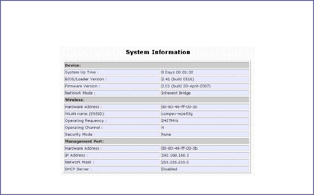
Page 170
Use the HELP menu
View About System
System Information displays system configuration information that may
be required by support technicians for troubleshooting.
Select A
Ab
bo
ou
ut
t
S
Sy
ys
st
te
em
m from the H
HE
EL
LP
P menu.
The S
Sy
ys
st
te
em
m
I
In
nf
fo
or
rm
ma
at
ti
io
on
n page displays information about the access point
configuration settings.
Page 171
Get Technical Support
This page displays the contact information of technical support centres
around the world.
If further information unavailable in the manual or data sheet is
required, please contact a Technical Support Centre by mail, email,
fax or telephone.
Click on G
Ge
et
t
T
Te
ec
ch
hn
ni
ic
ca
al
l
S
Su
up
pp
po
or
rt
t from the H
HE
EL
LP
P menu.

Page 172
Appendix: Use the Command Line
Interface
Get Operation List
SYNTAX DESCRIPTION
Get tasks Display all active process/tasks.
Get sysinfo Display system information.
Get aplist Display list of access points discovered.
Get athstats Display wireless driver information.
Get brinfo Display bridge and interfaces information.
Get brmacshow Display bridge learned MAC address list.
Get bssinfo. Display current radio information.
Get channel Display current wireless channel number.
Get chanlist Display current domain wireless channels.
Get ieee80211stats Display ieee80211 protocol statistics.
Get routeshow Display the routing table information.
Get stalist Display a list of currently associated stations.
Get linkinfo Display client link information (Client mode only)
Get macstats Display a list of currently learnt wireless device MAC addresses.
Get opmode Display current wireless operation mode.
Get wmode Display wireless mode
Set Operation List
SYNTAX DESCRIPTION
Set factorydefault Set factorydefault – restore configuration to factory default.
Restart Do a warm reboot.
Save Configuration
SYNTAX DESCRIPTION
Commit Save current configuration to flash.
Most commands require rebooting to take effect after saving.
Long Range
Check for recommended values from long distance option setup page.
SYNTAX DESCRIPTION
Set outdoor <enable/disable> Enable outdoor for long-range connection.
Set distance <value> Set the connection distant (value in decimal)
Set acktimeout <value> Set the ACK timeout (value in decimal)
Set ctstimeout <value> Set the CTS timeout (value in decimal)
Set slottimeout <value> Set the Slot timeout (value in decimal)
TX Power
SYNTAX DESCRIPTION
Set txpower <string> (Default full) auto, 1, 2, 3, 4, ..., 17, full, min
TX Rate
SYNTAX DESCRIPTION
Set txrate <string> Values are: (default auto)
(802.11a)-- 6, 9, 12, 18, 24, 36, 48, 54, auto (Version AG)
(802.11b/g mixed)-- 1, 2, 5,5, 11, 6, 9, 12, 18, 24, 36, 48, 54, auto
(802.11b-only)-- 1, 2, 5.5, 11, auto

Page 173
Wireless Mode
SYNTAX DESCRIPTION
Set wirelessmode <string> Supported strings are: auto, 11a, 11b, 11g, pureg, superg, supera
Set autochannelselect Enable/disable Enable or disable smart channel select during power up.
Set radio_off_eth_down enable/disable Enable or disable auto turn off radio when Ethernet port connection link is lost.
WEP Key
Must first set a key entry type, and then proceed to set the key index, size, and value.
SYNTAX DESCRIPTION
Set key <keyindex> <keysize> <keyvalue> Set keyentrymethod hex/ascii
Set key <keyindex> default Set default key.
Add or Delete User
SYNTAX DESCRIPTION
Set user < [-r|-w] > <password> username To add a user.
Set user –d username To delete user.
Country Code
SYNTAX DESCRIPTION
Set countrycode <iso.name>
Set countrycode <2 letter string>
List of countries:
{0, "NA" },
{CTRY_ALBANIA, "AL" },
{CTRY_ALGERIA, "DZ" },
{CTRY_ARGENTINA, "AR" },
{CTRY_ARMENIA, "AM" },
{CTRY_AUSTRALIA, "AU" },
{CTRY_AUSTRIA, "AT" },
{CTRY_AZERBAIJAN, "AZ" },
{CTRY_BAHRAIN, "BH" },
{CTRY_BELARUS, "BY" },
{CTRY_BELGIUM, "BE" },
{CTRY_BELIZE, "BZ" },
{CTRY_BOLIVIA, "BO" },
{CTRY_BRAZIL, "BR" },
{CTRY_BRUNEI_DARUSSALAM, "BN" },
{CTRY_BULGARIA, "BG" },
{CTRY_CANADA, "CA" },
{CTRY_CHILE, "CL" },
{CTRY_CHINA, "CN" },
{CTRY_COLOMBIA, "CO" },
{CTRY_COSTA_RICA, "CR" },
{CTRY_CROATIA, "HR" },
{CTRY_CYPRUS, "CY" },
{CTRY_CZECH, "CZ" },
{CTRY_DENMARK, "DK" },
{CTRY_DOMINICAN_REPUBLIC, "DO" },
{CTRY_ECUADOR, "EC" },
{CTRY_EGYPT, "EG" },
{CTRY_EL_SALVADOR, "SV" },
{CTRY_ESTONIA, "EE" },
{CTRY_FINLAND, "FI" },
{CTRY_FRANCE, "FR" },
{CTRY_FRANCE2, "F2" },
{CTRY_GEORGIA, "GE" },
{CTRY_GERMANY, "DE" },
{CTRY_GREECE, "GR" },
{CTRY_GUATEMALA, "GT" },
{CTRY_HONDURAS, "HN" },
{CTRY_HONG_KONG, "HK" },
{CTRY_HUNGARY, "HU" },
{CTRY_ICELAND, "IS" },
{CTRY_INDIA, "IN" },
{CTRY_INDONESIA, "ID" },
{CTRY_IRAN, "IR" },
{CTRY_IRELAND, "IE" },
{CTRY_ISRAEL, "IL" },

Page 174
{CTRY_ITALY, "IT" },
{CTRY_JAPAN, "JP" },
{CTRY_JAPAN1, "J1" },
{CTRY_JAPAN2, "J2" },
{CTRY_JAPAN3, "J3" },
{CTRY_JAPAN4, "J4" },
{CTRY_JAPAN5, "J5" },
{CTRY_JAPAN6, "J6" },
{CTRY_JORDAN, "JO" },
{CTRY_KAZAKHSTAN, "KZ" },
{CTRY_KOREA_NORTH, "KP" },
{CTRY_KOREA_ROC, "KR" },
{CTRY_KOREA_ROC2, "K2" },
{CTRY_KOREA_ROC3, "K3" },
{CTRY_KUWAIT, "KW" },
{CTRY_LATVIA, "LV" },
{CTRY_LEBANON, "LB" },
{CTRY_LIECHTENSTEIN, "LI" },
{CTRY_LITHUANIA, "LT" },
{CTRY_LUXEMBOURG, "LU" },
{CTRY_MACAU, "MO" },
{CTRY_MACEDONIA, "MK" },
{CTRY_MALAYSIA, "MY" },
{CTRY_MALTA, "MT" },
{CTRY_MEXICO, "MX" },
{CTRY_MONACO, "MC" },
{CTRY_MOROCCO, "MA" },
{CTRY_NETHERLANDS, "NL" },
{CTRY_NEW_ZEALAND, "NZ" },
{CTRY_NORWAY, "NO" },
{CTRY_OMAN, "OM" },
{CTRY_PAKISTAN, "PK" },
{CTRY_PANAMA, "PA" },
{CTRY_PERU, "PE" },
{CTRY_PHILIPPINES, "PH" },
{CTRY_POLAND, "PL" },
{CTRY_PORTUGAL, "PT" },
{CTRY_PUERTO_RICO, "PR" },
{CTRY_QATAR, "QA" },
{CTRY_ROMANIA, "RO" },
{CTRY_RUSSIA, "RU" },
{CTRY_SAUDI_ARABIA, "SA" },
{CTRY_SINGAPORE, "SG" },
{CTRY_SLOVAKIA, "SK" },
{CTRY_SLOVENIA, "SI" },
{CTRY_SOUTH_AFRICA, "ZA" },
{CTRY_SPAIN, "ES" },
{CTRY_SWEDEN, "SE" },
{CTRY_SWITZERLAND, "CH" },
{CTRY_SYRIA, "SY" },
{CTRY_TAIWAN, "TW" },
{CTRY_THAILAND, "TH" },
{CTRY_TRINIDAD_Y_TOBAGO, "TT" },
{CTRY_TUNISIA, "TN" },
{CTRY_TURKEY, "TR" },
{CTRY_UKRAINE, "UA" },
{CTRY_UAE, "AE" },
{CTRY_UNITED_KINGDOM, "GB" },
{CTRY_UNITED_STATES, "US" },
{CTRY_URUGUAY, "UY" },
{CTRY_UZBEKISTAN, "UZ" },
{CTRY_VENEZUELA, "VE" },
{CTRY_VIET_NAM, "VN" },
{CTRY_YEMEN, "YE" },
{CTRY_ZIMBABWE, "ZW" },

Page 175
Channel
SYNTAX DESCRIPTION
Set channel <value> (Value in decimal)
SSID
SYNTAX DESCRIPTION
Set ssid <string> (Not More than 32 characters)
Closed System
SYNTAX DESCRIPTION
Set hidessid enable/disable Enable or disable broadcasting of SSID.
Per Node
SYNTAX DESCRIPTION
Set apbridge enable/disable Enable or disable isolation of wireless client.
RTS, Fragment, and Beacon Interval
SYNTAX DESCRIPTION
Set rts <value (Value in decimal, default 2312, range 1 to 2312)
Set fragment <value> (Value in decimal, default 2346, range, 256 to 2346)
Set beaconintval <value> (Value in decimal, default 1, range 1 to 1000)
Set dtim <value> Data Beacon Rate (value in decimal, default 1, range 1 to 16384)
WLAN State
SYNTAX DESCRIPTION
Get wlanstate Display whether status of current wireless operation is Enabled or Disabled.
Set wlanstate enable/disable Set to Disable to turn off wireless operation.
Set to Enable to turn back on wireless operation.
Note:
When executing this command, please ensure that you are not connected on
wireless with device or you will be disconnected from the device and network.
The wireless operation can only be Enabled from the Ethernet port or UTP cable
connection to device.
Reset Button
SYNTAX DESCRIPTION
Get buttonpassreset Display the status of Reset Button operation.
If status is (Enabled), resetting of password by pressing Reset Button is allowed.
If status is (Disabled), resetting of password by pressing Reset Button is not allowed.
Set buttonpassreset enable/disable Set to Disable to prevent resetting of password by pressing Reset button.
Set to Enable to allow resetting of password by pressing Reset button.
Upgrade Firmware
SYNTAX Set upgrade <IP address of AP> <firmware image filename>
DESCRIPTION To upgrade firmware in CLI enter this command with the IP address of AP and the
firmware image filename.

Page 176
Custom Configuration Update
SYNTAX
Cfgfile <operation type> <IP of PC running TFTP server> <filename>
DESCRIPTION
The cfgfile command is used for managing simple configuration changes to multiple access points.
It is useful for when the user has many access points to configure and the configuration is mostly the same.
For example if user needs to configure ten access points, and just change the IP address configuration:
1. Configure the first access point with the common configuration for all the access points
using web manager
2. Export the access point configuration file with cfgfile in Telnet.
3. Edit the IP addresses in the access point configuration files to customise them for the
individual access points.
4. Import the edited access point configuration files to the respective access points with
cfgfile in Telnet.
Requirement and Explanation:
The cfgfile command uses the TFTP (Trivial File Transfer Protocol). This command transfers the access point
configuration file to and from the access point. It has 4 operation types for these transfers – Backup,
Restore, Export, and Import.
Before executing the cfgfile command, there are some requirements that have to be met in order for the
command to execute successfully. The TFTP server has to be running on the PC with the Telnet connection
to the access point.
Make a note of the directory where the access point configuration file is located in. This directory can be
a folder on the hard drive of the PC with the Telnet connection. It can also be any storage device that is
connected o this PC. The TFTP server has to be set up to point to this directory.
This table explains the different Operation Types.
Operation Type
Backup
The Backup operation saves the configuration from the access point to the configuration file
defined in <filename> and stored on the PC.
This is a binary file (*.bin) which must not be edited as doing so will corrupt it.
(Access Point PC)
Restore
The Restore operation returns the access point back to the previous configuration according
to the configuration file defined in <filename> on the PC.
This is a binary file (*.bin) which must not be edited as doing so will corrupt it.
(PC Access Point)
Export
The Export operation extracts a portion of the access point configuration to a text file on the
PC which can be edited to further customise it for each access point.
This text file can then be imported into other access points with the Import cfgfile operation.
(Access Point PC)
Import
The Import Operation uploads the configuration to the access point.
This configuration is the access point configuration which has been exported previously with
the Export cfgfile operation and then further edited to customise for each access point.
(PC Access Point)
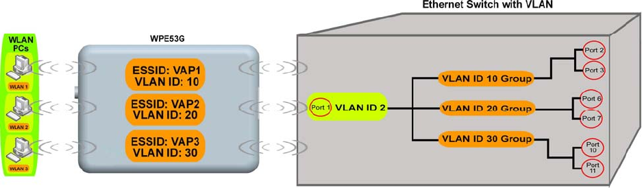
Page 177
Appendix: Virtual AP (Multi-SSID)
FAQ
Q1) What is mSSID?
Multi-SSID (mSSID) as the name suggest, allows an access point (AP)
with a single radio card to support more than one SSID.
Q2) What can you do with mSSID connection?
The application of mSSID is to provide better security with multiple
network path connections from a single AP, to multiple VLAN network
segments of the switch on the local area network.
A network setup application is illustrated below.
E.g.
Virtual AP with SSID: VAP1, VLAN ID: 10 and WPA-PSK wireless security
enabled will be channeled to Port 2 and Port 3 where the internet-
sharing router is connected.
Virtual AP with SSID: VPA2, VLAN ID: 20, WPA-EAP enabled, and
connected to a radius server, will be channeled to Port 5 and Port 6,
which are connected to the firewall of the internal local area network.
Page 178
Q3) Can I update my access point to this mSSID firmware?
Yes. You can retain your access point configuration when you update
to the mSSID firmware if the current firmware running is v1.3x and
above.
If AP is running the following configuration setup, updating to the mSSID
firmware will affect the configuration.
If AP is running as PtP (Point-To-Point) or PtMP (Point-To-MultiPoint) mode.
The reason it cannot retain the configuration is because mSSID uses a
new PtP and PtMP connection setup method called: RootAP and
Transparent Client. This method is compliant with IEEE 802.11h standard.
AP is running very old firmware v1.2x and below.
Q4) Can I update to mSSID firmware but setup only one SSID
connection?
Yes, mSSID firmware operation is similar to previous single SSID firmware
when setup with one SSID.
If the existing AP is running v1.3x firmware, after updating to mSSID it will
retain and continue to run the previous configuration. No
reconfiguration is needed.
Q5) I have a MAC Filtering table set from a previous firmware. Will
updating to mSSID cause the MAC table to be lost?
No, if your firmware is v1.3x and higher, updating to mSSID firmware will
retain all entries in the MAC table.
However, if you switch back from mSSID to the previous sSSID firmware,
the MAC table will be lost.
Page 179
Q6) I have Pseudo VLAN for Per Group enabled. Will updating to mSSID
firmware still support wireless clients with MAC addresses listed in Per
Group?
The mSSID firmware replaces Pseudo VLAN and integrates it into VAP
(Virtual AP) and MAC Filtering.
Thus, Pseudo VLAN with its VLAN ID and MAC listing will be lost after
updating to mSSID firmware.
Refer to the user manual on how to create new VAP with VLAN ID and
MAC Filtering.
Similarly, Per Node (control to isolate wireless station in AP) being part
of Pseudo VLAN will also be lost.
This option can be enabled again with the option "Station Isolation" in
VAP setup page.
Q7) I have WDS setup in my network. Will mSSID still support this?
WDS has the limitation that it can only support WEP security key.
To support higher wireless security it is replaced with Repeater mode in
mSSID firmware.
Thus, updating to mSSID will disconnect the WDS links and connections
with the rest of the APs.
It is recommended to connect directly to each AP to update the
firmware, then set to Repeater mode and configure it before updating
the next AP. This way you can build back the connections.
Refer to the user manual for more details instructions on the setup.
Updating to the mSSID firmware is not necessary if you do not need the
higher wireless security support.
Page 180
Q8) I have 2 of the access point units installed at a site about 2km from
each other running PtP modes.
Should I update to mSSID firmware? Can I do it from one location to
update the firmware like I do with the current single SSID firmware?
The setup for PtP and PtMP for mSSID firmware is different the current
sSSID firmware.
After mSSID firmware starts up, the link between the 2 APs will be lost.
The recommended method is to setup 2 similar model units in the office.
Load the mSSID firmware and create the new PtP / PtMP configuration
using the actual parameters of the 2 units on site that you will update.
After testing the connection to be working in the office, backup the
configuration file for each unit.
Go to the first site to update the mSSID firmware and restore the
configuration for the site, then go to the next site and do the same.
When both APs are up again, the network at both sides should be
connected with the new PtP setup.
** Note: If existing PtP connection is running well, it is not necessary to
update to the mSSID firmware.
Unless you have the following concerns:
Current firmware PtP is not compliant with IEEE 802.11h standard and
the respective country authority requires it to be changed.
Current firmware PtP wireless security only supports WEP key and you
are very concerned about the vulnerability to being hacked.

Page 181
Appendix: View the Technical
Specifications
Safety and Electromagnetic
Conformance
• FCC Part 15 SubPart B and SubPart C (for wireless module)
• EN 300 328-2
• EMC CE EN 301 489 (EN300 826)
• EN 55022 (CISPR 22)/EN 55024 Class B
• EN 61000-3-2
• EN61000-3-3
• CE EN 60950
Standards
IEEE802.11b:
IEEE802.11g:
Super-G:
• 11Mbps, 5.5Mbps, 2Mbps, 1Mbps
• 54Mbps, 48Mbps, 36Mbps, 24Mbps, 18Mbps, 12Mbps, 9Mbps, 6Mbps, automatically fallback to
5.5Mbps, 2Mbps, 1Mbps
• 108Mbps, 96Mbps, 72Mbps, 54Mbps, 48Mbps, 36Mbps, 24Mbps, 18Mbps, 12Mbps, 6Mbps
Frequency Range IEEE
802.11b/g:
2.412GHz ~ 2.462GHz (US & Canada)
2.412GHz ~ 2.472GHz (Europe)
2.412GHz ~ 2.484GHz (Japan)
Max Tx Power:
17dBm
Security
• 64 - bit / 128 - bit WEP
• WPA-EAP, WPA-PSK, WPA2
• Tagged VLAN
• IEEE 802.1x – TLS, TTLS, PEAP, EAP-SIM
Network Interface
• 10/100 Mbps auto-negotiating Ethernet port (RJ45)
Modulation Techniques
OFDM (BPSK, QPSK, 16-QAM, 64-QAM), DSSS (BPSK, QPSK, CCK)
Operating Channels
• 11 Channels (US and Canada)
• 13 Channels (Europe)
• 14 Channels (Japan)
Advanced Wireless Feature
• Virtual AP
• Long Distance Parameters Setup
• Smart Select
• STP
• HTTPS
Antenna
Detachable 2dBi antenna with SMA connector
Management
• HTTP Web Management
• SNMP - SNMP (RFC1157)
- SNMP (RFC1213)
• Telnet
• SSH
Built-in DHCP Server
Yes
DHCP Reservation
By MAC address

Page 182
Configuration Backup & Restore
Yes
Firmware Upgrade
Yes
Power Requirements
Using Power Adapter:
Using PoE:
24VDC
15-48VDC
Operating Temp:
-20ºC to +70ºC
Storage Temp:
-30ºC to +80ºC
Operating Humidity:
10% to 80% RH
Humidity (RH – Relative Humidity)
Physical Dimensions
91.8mm x 66mm x 25mm (H x W x D)
Page 183
© Copyright 2007 Compex Systems Pte Ltd
All Rights Reserved
This document contains information, which is protected by copyright. Reproduction,
adaptation or translation without prior permission is prohibited, except as allowed under the
copyright laws.
Trademark Information
Compex® is a registered trademark of Compex, Inc. Microsoft Windows and the Windows logo
are the trademarks of Microsoft Corp. NetWare is the registered trademark of Novell Inc. All
other brand and product names are trademarks or registered trademarks of their respective
owners.
Notice: Copyrights © 2007 by Compex, Inc. All rights reserved. Reproduction, adaptation, or
translation without prior permission of Compex, Inc. is prohibited, except as allowed under the
copyright laws.
Manual Revision by Daniel
Manual Number: U-0587-V1.1C Version 1.1 August 2007
Disclaimer
Compex, Inc. provides this manual without warranty of any kind, expressed or implied,
including but not limited to the implied warranties of merchantability and fitness for a particular
purpose. Compex, Inc. may make improvements and/or changes to the product and/or
specifications of the product described in this manual, without prior notice. Compex, Inc will
not be liable for any technical inaccuracies or typographical errors found in this guide.
Changes are periodically made to the information contained herein and will be incorporated
into later versions of the manual. The information contained is subject to change without prior
notice.
FCC NOTICE
This device has been tested and found to comply with the limits for a Class B digital device,
pursuant to Part 15 of the FCC Rules. These limits are designed to provide reasonable
protection against harmful interference in a residential installation. This device generates, uses
and can radiate radio frequency energy and, if not installed and used in accordance with the
instructions, may cause harmful interference to radio communications. However, there is no
guarantee that interference will not occur in a particular installation. If this device does cause
harmful interference to radio or television reception, the user is encouraged to try to correct
the interference by one or more of the following measures:
• Reorient or relocate the receiving antenna.
• Connect the computer into an outlet on a circuit different from that to which the receiver is
connected.
• Increase the separation between the computer and receiver.
• Consult the dealer or an experienced radio/TV technician for help.
Caution: Any changes or modifications not expressly approved by the grantee of this device
could void the user's authority to operate the equipment.

Page 184
FCC Compliance Statement: This device complies with Part 15 of the FCC Rules. Operation is
subject to the following two conditions:
This device may not cause harmful interference, and
This device must accept any interference received, including interference that may cause
undesired operation.
Products that contain a radio transmitter are labelled with FCC ID and may also carry the FCC
logo.
Caution: Exposure to Radio Frequency Radiation.
To comply with the FCC RF exposure compliance requirements, the following antenna
installation and device operating configurations must be satisfied:
a. For configurations using the integral antenna, the separation distance between the
antenna(s) and any person’s body (including hands, wrists, feet and ankles) must be at
least 2.5cm (1 inch).
b. For configurations using an approved external antenna, the separation distance between
the antenna and any person’s body (including hands, wrists, feet and ankles) must be at
least 20cm (8 inch).
The transmitter shall not be collocated with other transmitters or antennas.
ICES 003 Statement
This Class B digital apparatus complies with Canadian ICES-003.
Declaration of Conformity
Compex, Inc. declares the following:
Product Name: Wireless Network Access Point
Model No.: WPE53G conforms to the following Product Standards:
This device complies with the Electromagnetic Compatibility Directive (89/336/EEC) issued by
the Commission of the European Community. Compliance with this directive implies conformity
to the following European Norms (in brackets are the equivalent international standards.)
Electromagnetic Interference (Conduction and Radiation): EN 55022 (CISPR 22)
Electromagnetic Immunity: EN 55024 (IEC61000-4-2, 3, 4, 5, 6, 8, 11)
Low Voltage Directive: EN 60 950: 1992+A1: 1993+A2: 1993+A3: 1995+A4: 1996+A11: 1997.
Therefore, this product is in conformity with the following regional standards: FCC Class B:
following the provisions of FCC Part 15 directive, CE Mark: following the provisions of the EC
directive.
Compex, Inc. also declares that:
The wireless card in this product complies with the R&TTE Directive (1999/5/EC) issued by the
Commission of the European Community. Compliance with this directive implies conformity to
the following:
EMC Standards: FCC: 47 CFR Part 15, Subpart B, 47 CFR Part 15, Subpart C (Section 15.247); CE:
EN 300 328-2, EN 300 826 (EN 301 489-17)
Therefore, this product is in conformity with the following regional standards: FCC Class B:
following the provisions of FCC Part 15 directive, CE Mark: following the provisions of the EC
directive.
Firmware
This manual is written based on Firmware version 2

Page 185
Technical Support Information
The warranty information and registration form are found in the Quick
Install Guide.
For technical support, you may contact Compex or its subsidiaries. For
your convenience, you may also seek technical assistance from the
local distributor, or from the authorized dealer/reseller that you have
purchased this product from. For technical support by email, write to
support@compex.com.sg.
Refer to the table below for the nearest Technical Support Centres:
Technical Support Centres
Contact the technical support centre that services your location.
U.S.A., Canada, Latin America and South America
Write
Compex, Inc.
840 Columbia Street, Suite B
Brea, CA 92821, USA
Call
Fax
Tel:
Tel:
Fax:
+1 (714) 482-0333 (8 a.m.-5 p.m. Pacific time)
+1 (800) 279-8891 (Ext.122 Technical Support)
+1 (714) 482-0332
Asia, Australia, New Zealand, Middle East and the rest of the World
Write
Compex Systems Pte Ltd
135, Joo Seng Road #08-01, PM Industrial Building
Singapore 368363
Call
Tel:
Tel:
Fax:
(65) 6286-1805 (8 a.m.-5 p.m. local time)
(65) 6286-2086 (Ext.199 Technical Support)
(65) 6283-8337
Internet
access E-mail:
FTPsite: support@compex.com.sg
ftp.compex.com.sg
Website: http://www.cpx.com or http://www.compex.com.sg
We value your feedback. If you have any suggestions on improving, we
would like to hear from you.
Please contact us at:
Fax: (65) 62809947
Email: feedback@compex.com.sg
We hope this manual was helpful to you. For more Compex information,
please visit us at www.Compex.com.sg
Fax

Page 186
warning
Class B:
This equipment has been tested and found to comply with the limits for a
Class B digital device, pursuant to part 15 of the FCC Rules. These limits are
designed to provide reasonable protection against harmful interference in a residential
installation. This equipment generates, uses and can radiate radio frequency energy
and, if not installed and used in accordance with the instructions, may cause harmful
interference to radio communications. However, there is no guarantee that
interference will not occur in a particular installation. If this equipment does cause
harmful interference to radio or television reception, which can be determined by
turning the equipment off and on, the user is encouraged to try to correct the
interference by one or more of the following measures:
-Reorient or relocate the receiving antenna.
-Increase the separation between the equipment and receiver.
-Connect the equipment into an outlet on a circuit different from that to which
the receiver is connected.
-Consult the dealer or an experienced radio/ TV technician for help.
CAUTION:
Any changes or modifications not expressly approved by the grantee of this device
could void the user's authority to operate the equipment.
RF exposure warning
This equipment must be installed and operated in accordance with provided instructions
and the antenna(s) used for this transmitter must be installed to provide a separation
distance of at least 20 cm from all persons and must not be co-located or operating in
conjunction with any other antenna or transmitter. End-users and installers must be
provide with antenna installation instructions and transmitter operating conditions for
satisfying RF exposure compliance.